EP1662929B1 - Slider element of a zip fastener - Google Patents
Slider element of a zip fastener Download PDFInfo
- Publication number
- EP1662929B1 EP1662929B1 EP04742251A EP04742251A EP1662929B1 EP 1662929 B1 EP1662929 B1 EP 1662929B1 EP 04742251 A EP04742251 A EP 04742251A EP 04742251 A EP04742251 A EP 04742251A EP 1662929 B1 EP1662929 B1 EP 1662929B1
- Authority
- EP
- European Patent Office
- Prior art keywords
- spring
- fastening
- slider element
- pull tag
- zip fastener
- Prior art date
- Legal status (The legal status is an assumption and is not a legal conclusion. Google has not performed a legal analysis and makes no representation as to the accuracy of the status listed.)
- Expired - Lifetime
Links
Images

Classifications
-
- A—HUMAN NECESSITIES
- A44—HABERDASHERY; JEWELLERY
- A44B—BUTTONS, PINS, BUCKLES, SLIDE FASTENERS, OR THE LIKE
- A44B19/00—Slide fasteners
- A44B19/24—Details
- A44B19/26—Sliders
- A44B19/30—Sliders with means for locking in position
- A44B19/306—Sliders with means for locking in position in the form of a locking spring member actuated by the pull member
Definitions
- the invention relates to a slider element of a zip fastener which comprises a body with a tunnel for the rows of coupling elements comprised in the zip fastener, a pull tag with a fastening and pivoting axis, and a spring that locks the fastening and pivoting axis of the pull tag to the body, the spring being equipped with opposite ends, between which the spring extends in the sliding direction of the slider element, one of the ends being formed as a fastening end having a gripping part attached to a formed counterpart of the body, and a slide-locking projection which is biased to the slide-locking position extending into the tunnel due to the spring effect of the spring, whereby, when the spring is loaded by the pull tag in direction transverse to the tunnel, yielding of the spring releases the slide-locking projection from its slide locking position.
- a zip fastener slider element of the above-mentioned type (a so-called cam-lock solution), in which the spring effect affects the turning of the pull tag, that is, there is a cam on the pull tag, which bends the spring when the pull tag is turned and at the same time lifts the slide-locking projection connected to the spring up from the tunnel.
- the spring are the lugs of the fastening and pivoting axis of the pull tag, and the spring for its part is fixed to the body with lugs that must be bent during assembly. This requires an assembling machine.
- US-A-4,074,399 shows a slider for a slide fastener wherein the locking spring includes a locking prong extending through a slider body to engage the coupling elements of the slide fastener to lock the slider. Pulling on the pull tab in either direction cams the cross bar of the pull tab upward to release the lock and allow movements of the slider.
- the locking prong is formed of movable end of the locking spring, which is fastened to the body by retention arms formed midway along its sides.
- US-A-4,662,036 shows a slider for a slide fastener, having a bendable spring tongue movable through a window in the spring plate which is fastened to the slider body.
- the end of the spring tongue forms the slide-locking projection.
- EP-A-0,251,316 shows an automatic lock slider for a slide fastener.
- a locking spring has a spring-biased locking prong which protrudes into a y-shaped quide channel in a slider body.
- One end of the locking spring has been attached to the body, the other end being movable transversally to the sliding direction to allow the spring biased movement of the locking spring.
- the aim of the invention is to provide a slider element of a zip fastener of the above type that is easy to assemble (even manually) and which is structurally strong, especially in such a way that the spring and pull tag are tightly locked to the body.
- a particular advantage of the solution according to the invention is that as the load increases, the curved spring fixed at both ends bites even more tightly into its notches.
- the slider element in the solution according to the invention may be of metal or plastic.
- the slider element according to the invention may be of the cam-lock or auto-lock type. The solution is cheap and simple and does not have the scraping surfaces of a spring member.
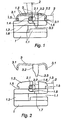
- the body 1 of the slider element is a tunnel 1.1 for the rows of coupling elements of the zip fastener.
- the top and bottom parts of the body are joined together by means of a core part 1.2, which divides one end of the tunnel 1.1 into two tunnel branches, in which the rows of coupling elements separated by the core part 1.2 slide when the zip fastener is being opened or dosed. Since the body 1 causes the rows of coupling elements to open and dose, the body 1 is also called a lock.
- the slider element also comprises a pull tag 2 and a spring 3, which locks the pull tag 2 to the body In a manner described in greater detail below.
- the spring 3 is provided with a slide-locking projection 3.3, which returns to the slide-locking position extending into the tunnel 1.1 due to the spring effect of the spring 3.
- gripping parts 3.1 At opposite ends of the spring 3 are formed gripping parts 3.1, by means of which the detached, curved spring 3 can be attached to the formed counterparts 1.5.
- These formed counterparts 1.5 are located at opposite ends of the lugs 1.3 on top of the body.
- the ends of the lugs 1.3 are formed into guiding arcs that distance the formed gripping parts 3.1 of the spring 3 against the spring force, that is, straighten the curvature of the spring 3 when the spring 3 is pressed into place in the body between the lugs 1.3 from above, until the formed gripping parts 3.1 snap into the formed counterparts 1.5 due to the spring effect of the spring 3.
- the formed gripping parts 3.1 are pins or similar projections at opposite ends of the spring 3, and the formed counterparts 1.5 are notches opening in opposite directions into which the pins 3.1 snap In place.
- the gripping pins 3.1 bite even more tightly into the notches 1.5.
- the lugs 1.3 of the body is an upwards open notch 1.6 which is connected a notch 1.4 open on one side which receives the fastening and a pivoting axis 2.1 of the pull tag 2.
- the open side of the notch 1.4 is closed by a branch 3.2 projecting from the spring 3.
- the slide-locking projection 3.3 is an extension of the branch 3.2 of the spring. The branch 3.2 of the spring thus locks the fastening and a pivoting axis of the pull tag into place by closing the notch 1.4 and by thus preventing the movement of the fastening and pivoting axis 2.1 in the longitudinal direction of the tunnel 1.1 with respect to the body 1.
- the same projection 3.3 also rises up from the tunnel 1.1, whereby the slider element is able to slide to open or dose the zip fastener.
- On the top surface, that is the cover, of the body 1 is a recess 1.8 which receives the cam 2.2.
- the hole 1.7 Is at the bottom of the recess 1.8.
- the spring 3 is designed in such a way that adjacent to both its fastening ends 3.1 are arches in one direction, and between these arches there is curvature in the spring In the opposite direction.
- the last-mentioned curvature is at the branch 3.2 and at the projection 3.3.
- the cam 2.2 bends the spring 3 by reducing the curvature of these arches, that is, three separate arches form what is closer to one large uniform arch.
- the spring is, therefore, subjected simultaneously to bending stress and tensile stress when the pull tag is pulled or when the pull tag is turned. Simultaneous bending and tensile stress provide many advantages.
- the tension fixes the formed gripping parts 3.1 even more tightly into place. Materials - even plastic material - withstand tension well. This solution offers for the first time the possibility of making the spring 3 of plasitic.
- the embodiment described above is thus of the cam-lock type.
- An auto-lock type solution is realised in such a way that the fastening and pivoting axis 2.1 is not locked into place but is able to move in the notches of the lugs 1.3 against the spring 3, whereby when the pull tag 2 is pulled, the spring 3 bends and is subjected, with its part between the formed gripping parts 3.1, to the bending and tensile stress in the same way as when lifted by the cam 2.2.
- the tensile stress of the spring 3 has the additional significance that it receives excessive loads directed at the pull tag and thus substantially reduces the risk of damage.
Landscapes
- Slide Fasteners (AREA)
- Clamps And Clips (AREA)
- Purses, Travelling Bags, Baskets, Or Suitcases (AREA)
- Buckles (AREA)
Priority Applications (1)
| Application Number | Priority Date | Filing Date | Title |
|---|---|---|---|
| PL04742251T PL1662929T3 (pl) | 2003-08-01 | 2004-06-23 | Element suwakowy zamka błyskawicznego |
Applications Claiming Priority (2)
| Application Number | Priority Date | Filing Date | Title |
|---|---|---|---|
| FI20035128A FI20035128A7 (fi) | 2003-08-01 | 2003-08-01 | Vetoketjun liukuelementti |
| PCT/FI2004/050101 WO2005011426A1 (en) | 2003-08-01 | 2004-06-23 | Slider element of a zip fastener |
Publications (2)
| Publication Number | Publication Date |
|---|---|
| EP1662929A1 EP1662929A1 (en) | 2006-06-07 |
| EP1662929B1 true EP1662929B1 (en) | 2008-04-09 |
Family
ID=27839072
Family Applications (1)
| Application Number | Title | Priority Date | Filing Date |
|---|---|---|---|
| EP04742251A Expired - Lifetime EP1662929B1 (en) | 2003-08-01 | 2004-06-23 | Slider element of a zip fastener |
Country Status (8)
| Country | Link |
|---|---|
| EP (1) | EP1662929B1 (pl) |
| CN (1) | CN100571562C (pl) |
| AT (1) | ATE391434T1 (pl) |
| DE (1) | DE602004013019T2 (pl) |
| ES (1) | ES2300793T3 (pl) |
| FI (1) | FI20035128A7 (pl) |
| PL (1) | PL1662929T3 (pl) |
| WO (1) | WO2005011426A1 (pl) |
Families Citing this family (1)
| Publication number | Priority date | Publication date | Assignee | Title |
|---|---|---|---|---|
| US8567019B2 (en) | 2011-04-18 | 2013-10-29 | Ykk Corporation Of America | Semi-automatic slider |
Citations (1)
| Publication number | Priority date | Publication date | Assignee | Title |
|---|---|---|---|---|
| EP0251613A2 (en) * | 1986-06-23 | 1988-01-07 | Institute For Industrial Research And Standards | A keyboard security device |
Family Cites Families (14)
| Publication number | Priority date | Publication date | Assignee | Title |
|---|---|---|---|---|
| US2197690A (en) * | 1939-12-12 | 1940-04-16 | Us Rubber Co | Slider for separable fasteners |
| GB644482A (en) * | 1948-05-07 | 1950-10-11 | Aero Zipp Fasteners Ltd | Improvements in or relating to sliding clasp fasteners |
| US3070865A (en) * | 1962-01-05 | 1963-01-01 | Scovill Manufacturing Co | Spring-locking slider for zipper fasteners |
| DE2210872A1 (de) * | 1972-03-07 | 1973-09-20 | Opti Holding Ag | Reissverschlusschieber |
| US4074399A (en) * | 1976-11-08 | 1978-02-21 | Textron, Inc. | Slider for slide fastener |
| GB2051221B (en) * | 1979-06-14 | 1983-08-10 | Rhondda Pressings Ltd | Sliding clasp fasteners |
| GB2072256B (en) * | 1980-03-04 | 1983-12-21 | Yoshida Kogyo Kk | Automatic lock slider for slide fasteners |
| JPS5724130B1 (pl) * | 1981-02-25 | 1982-05-22 | ||
| DE3437467A1 (de) * | 1984-10-12 | 1986-04-24 | Opti Patent-, Forschungs- Und Fabrikations-Ag, Riedern-Allmeind | Reissverschlussschieber |
| JPH0757204B2 (ja) * | 1986-07-04 | 1995-06-21 | ワイケイケイ株式会社 | 停止装置付きスライダーを有するスライドファスナー |
| JPH0721123Y2 (ja) * | 1988-10-22 | 1995-05-17 | ワイケイケイ株式会社 | 自動停止装置付スライドフアスナー用スライダー |
| JP3393572B2 (ja) * | 1996-04-30 | 2003-04-07 | ワイケイケイ株式会社 | 自動停止装置付スライドファスナー用スライダーおよびそのスライダーのカバー成形金型 |
| JPH10127313A (ja) * | 1996-10-31 | 1998-05-19 | Ykk Corp | 自動停止装置付スライドファスナー用スライダー |
| JP3714534B2 (ja) * | 2001-04-23 | 2005-11-09 | Ykk株式会社 | 停止装置付スライドファスナー用スライダー |
-
2003
- 2003-08-01 FI FI20035128A patent/FI20035128A7/fi not_active Application Discontinuation
-
2004
- 2004-06-23 EP EP04742251A patent/EP1662929B1/en not_active Expired - Lifetime
- 2004-06-23 PL PL04742251T patent/PL1662929T3/pl unknown
- 2004-06-23 AT AT04742251T patent/ATE391434T1/de not_active IP Right Cessation
- 2004-06-23 DE DE602004013019T patent/DE602004013019T2/de not_active Expired - Lifetime
- 2004-06-23 CN CNB2004800214683A patent/CN100571562C/zh not_active Expired - Fee Related
- 2004-06-23 ES ES04742251T patent/ES2300793T3/es not_active Expired - Lifetime
- 2004-06-23 WO PCT/FI2004/050101 patent/WO2005011426A1/en not_active Ceased
Patent Citations (1)
| Publication number | Priority date | Publication date | Assignee | Title |
|---|---|---|---|---|
| EP0251613A2 (en) * | 1986-06-23 | 1988-01-07 | Institute For Industrial Research And Standards | A keyboard security device |
Also Published As
| Publication number | Publication date |
|---|---|
| DE602004013019T2 (de) | 2009-07-23 |
| CN1829456A (zh) | 2006-09-06 |
| ATE391434T1 (de) | 2008-04-15 |
| PL1662929T3 (pl) | 2008-09-30 |
| DE602004013019D1 (pl) | 2008-05-21 |
| EP1662929A1 (en) | 2006-06-07 |
| ES2300793T3 (es) | 2008-06-16 |
| CN100571562C (zh) | 2009-12-23 |
| FI20035128A7 (fi) | 2003-08-15 |
| WO2005011426A1 (en) | 2005-02-10 |
Similar Documents
| Publication | Publication Date | Title |
|---|---|---|
| KR100993644B1 (ko) | 역개방 슬라이드 파스너 | |
| US8108975B2 (en) | Karabiner | |
| US7722492B2 (en) | Closing link for a bicycle chain | |
| EP1201147B1 (en) | Releasable bottom end stop for slide fastener | |
| AU702740B2 (en) | Tie | |
| US5884373A (en) | Auto-lock slider for slide fastener | |
| US6009602A (en) | Separable bottom end stop and a slider having a locking mechanism of a slide fastener | |
| US4081883A (en) | Locking slider for sliding clasp fasteners | |
| US6634066B2 (en) | Upper stopper device for slide fastener | |
| US20170224062A1 (en) | Slider for Slide Fastener | |
| CN100512699C (zh) | 凹形带扣 | |
| US8782859B2 (en) | Concealed slide fastener | |
| DK163271B (da) | Deleligt endeled til oplukkelig lynlaas | |
| US20080066269A1 (en) | Bottom end stop for a slide fastener, and a slide fastener comprising such a bottom end stop | |
| KR880010209A (ko) | 슬라이더 자물쇠 장치 | |
| EP0366022B1 (en) | Automatic lock slider for slide fastener | |
| EP1103198A1 (en) | Locking device for shoelaces | |
| CN111936007B (zh) | 拉头和具备该拉头的拉链 | |
| US3068542A (en) | Three-piece spring locking slider | |
| WO2005011426A1 (en) | Slider element of a zip fastener | |
| TWI630882B (zh) | Zipper slider | |
| US3952379A (en) | Automatically locking slider | |
| US4615083A (en) | Locking slider for slide fastener and method of production thereof | |
| DE102020004556B4 (de) | Schnalle und Einsteckteil einer Schnalle | |
| CN111315251B (zh) | 拉链用拉头 |
Legal Events
| Date | Code | Title | Description |
|---|---|---|---|
| PUAI | Public reference made under article 153(3) epc to a published international application that has entered the european phase |
Free format text: ORIGINAL CODE: 0009012 |
|
| 17P | Request for examination filed |
Effective date: 20060301 |
|
| AK | Designated contracting states |
Kind code of ref document: A1 Designated state(s): AT BE BG CH CY CZ DE DK EE ES FI FR GB GR HU IE IT LI LU MC NL PL PT RO SE SI SK TR |
|
| DAX | Request for extension of the european patent (deleted) | ||
| 17Q | First examination report despatched |
Effective date: 20070323 |
|
| GRAP | Despatch of communication of intention to grant a patent |
Free format text: ORIGINAL CODE: EPIDOSNIGR1 |
|
| GRAS | Grant fee paid |
Free format text: ORIGINAL CODE: EPIDOSNIGR3 |
|
| GRAA | (expected) grant |
Free format text: ORIGINAL CODE: 0009210 |
|
| AK | Designated contracting states |
Kind code of ref document: B1 Designated state(s): AT BE BG CH CY CZ DE DK EE ES FI FR GB GR HU IE IT LI LU MC NL PL PT RO SE SI SK TR |
|
| REG | Reference to a national code |
Ref country code: GB Ref legal event code: FG4D |
|
| REG | Reference to a national code |
Ref country code: CH Ref legal event code: EP |
|
| REG | Reference to a national code |
Ref country code: IE Ref legal event code: FG4D |
|
| REF | Corresponds to: |
Ref document number: 602004013019 Country of ref document: DE Date of ref document: 20080521 Kind code of ref document: P |
|
| REG | Reference to a national code |
Ref country code: ES Ref legal event code: FG2A Ref document number: 2300793 Country of ref document: ES Kind code of ref document: T3 |
|
| PG25 | Lapsed in a contracting state [announced via postgrant information from national office to epo] |
Ref country code: SI Free format text: LAPSE BECAUSE OF FAILURE TO SUBMIT A TRANSLATION OF THE DESCRIPTION OR TO PAY THE FEE WITHIN THE PRESCRIBED TIME-LIMIT Effective date: 20080409 |
|
| REG | Reference to a national code |
Ref country code: PL Ref legal event code: T3 |
|
| NLV1 | Nl: lapsed or annulled due to failure to fulfill the requirements of art. 29p and 29m of the patents act | ||
| PG25 | Lapsed in a contracting state [announced via postgrant information from national office to epo] |
Ref country code: BG Free format text: LAPSE BECAUSE OF FAILURE TO SUBMIT A TRANSLATION OF THE DESCRIPTION OR TO PAY THE FEE WITHIN THE PRESCRIBED TIME-LIMIT Effective date: 20080709 Ref country code: PT Free format text: LAPSE BECAUSE OF FAILURE TO SUBMIT A TRANSLATION OF THE DESCRIPTION OR TO PAY THE FEE WITHIN THE PRESCRIBED TIME-LIMIT Effective date: 20080910 Ref country code: FI Free format text: LAPSE BECAUSE OF FAILURE TO SUBMIT A TRANSLATION OF THE DESCRIPTION OR TO PAY THE FEE WITHIN THE PRESCRIBED TIME-LIMIT Effective date: 20080409 Ref country code: NL Free format text: LAPSE BECAUSE OF FAILURE TO SUBMIT A TRANSLATION OF THE DESCRIPTION OR TO PAY THE FEE WITHIN THE PRESCRIBED TIME-LIMIT Effective date: 20080409 |
|
| PG25 | Lapsed in a contracting state [announced via postgrant information from national office to epo] |
Ref country code: AT Free format text: LAPSE BECAUSE OF FAILURE TO SUBMIT A TRANSLATION OF THE DESCRIPTION OR TO PAY THE FEE WITHIN THE PRESCRIBED TIME-LIMIT Effective date: 20080409 |
|
| ET | Fr: translation filed | ||
| PG25 | Lapsed in a contracting state [announced via postgrant information from national office to epo] |
Ref country code: CZ Free format text: LAPSE BECAUSE OF FAILURE TO SUBMIT A TRANSLATION OF THE DESCRIPTION OR TO PAY THE FEE WITHIN THE PRESCRIBED TIME-LIMIT Effective date: 20080409 Ref country code: SE Free format text: LAPSE BECAUSE OF FAILURE TO SUBMIT A TRANSLATION OF THE DESCRIPTION OR TO PAY THE FEE WITHIN THE PRESCRIBED TIME-LIMIT Effective date: 20080709 Ref country code: DK Free format text: LAPSE BECAUSE OF FAILURE TO SUBMIT A TRANSLATION OF THE DESCRIPTION OR TO PAY THE FEE WITHIN THE PRESCRIBED TIME-LIMIT Effective date: 20080409 Ref country code: MC Free format text: LAPSE BECAUSE OF NON-PAYMENT OF DUE FEES Effective date: 20080630 |
|
| REG | Reference to a national code |
Ref country code: CH Ref legal event code: PL |
|
| PLBE | No opposition filed within time limit |
Free format text: ORIGINAL CODE: 0009261 |
|
| STAA | Information on the status of an ep patent application or granted ep patent |
Free format text: STATUS: NO OPPOSITION FILED WITHIN TIME LIMIT |
|
| PG25 | Lapsed in a contracting state [announced via postgrant information from national office to epo] |
Ref country code: BE Free format text: LAPSE BECAUSE OF FAILURE TO SUBMIT A TRANSLATION OF THE DESCRIPTION OR TO PAY THE FEE WITHIN THE PRESCRIBED TIME-LIMIT Effective date: 20080409 Ref country code: RO Free format text: LAPSE BECAUSE OF FAILURE TO SUBMIT A TRANSLATION OF THE DESCRIPTION OR TO PAY THE FEE WITHIN THE PRESCRIBED TIME-LIMIT Effective date: 20080409 Ref country code: SK Free format text: LAPSE BECAUSE OF FAILURE TO SUBMIT A TRANSLATION OF THE DESCRIPTION OR TO PAY THE FEE WITHIN THE PRESCRIBED TIME-LIMIT Effective date: 20080409 |
|
| 26N | No opposition filed |
Effective date: 20090112 |
|
| PG25 | Lapsed in a contracting state [announced via postgrant information from national office to epo] |
Ref country code: IE Free format text: LAPSE BECAUSE OF NON-PAYMENT OF DUE FEES Effective date: 20080623 Ref country code: EE Free format text: LAPSE BECAUSE OF FAILURE TO SUBMIT A TRANSLATION OF THE DESCRIPTION OR TO PAY THE FEE WITHIN THE PRESCRIBED TIME-LIMIT Effective date: 20080409 |
|
| PG25 | Lapsed in a contracting state [announced via postgrant information from national office to epo] |
Ref country code: CH Free format text: LAPSE BECAUSE OF NON-PAYMENT OF DUE FEES Effective date: 20080630 Ref country code: LI Free format text: LAPSE BECAUSE OF NON-PAYMENT OF DUE FEES Effective date: 20080630 |
|
| PG25 | Lapsed in a contracting state [announced via postgrant information from national office to epo] |
Ref country code: CY Free format text: LAPSE BECAUSE OF FAILURE TO SUBMIT A TRANSLATION OF THE DESCRIPTION OR TO PAY THE FEE WITHIN THE PRESCRIBED TIME-LIMIT Effective date: 20080409 |
|
| PG25 | Lapsed in a contracting state [announced via postgrant information from national office to epo] |
Ref country code: LU Free format text: LAPSE BECAUSE OF NON-PAYMENT OF DUE FEES Effective date: 20080623 Ref country code: HU Free format text: LAPSE BECAUSE OF FAILURE TO SUBMIT A TRANSLATION OF THE DESCRIPTION OR TO PAY THE FEE WITHIN THE PRESCRIBED TIME-LIMIT Effective date: 20081010 |
|
| PGFP | Annual fee paid to national office [announced via postgrant information from national office to epo] |
Ref country code: ES Payment date: 20100623 Year of fee payment: 7 Ref country code: FR Payment date: 20100706 Year of fee payment: 7 |
|
| PGFP | Annual fee paid to national office [announced via postgrant information from national office to epo] |
Ref country code: IT Payment date: 20100626 Year of fee payment: 7 Ref country code: PL Payment date: 20100602 Year of fee payment: 7 |
|
| PG25 | Lapsed in a contracting state [announced via postgrant information from national office to epo] |
Ref country code: GR Free format text: LAPSE BECAUSE OF FAILURE TO SUBMIT A TRANSLATION OF THE DESCRIPTION OR TO PAY THE FEE WITHIN THE PRESCRIBED TIME-LIMIT Effective date: 20080710 |
|
| PGFP | Annual fee paid to national office [announced via postgrant information from national office to epo] |
Ref country code: DE Payment date: 20100625 Year of fee payment: 7 Ref country code: GB Payment date: 20100618 Year of fee payment: 7 Ref country code: TR Payment date: 20100525 Year of fee payment: 7 |
|
| GBPC | Gb: european patent ceased through non-payment of renewal fee |
Effective date: 20110623 |
|
| PG25 | Lapsed in a contracting state [announced via postgrant information from national office to epo] |
Ref country code: IT Free format text: LAPSE BECAUSE OF NON-PAYMENT OF DUE FEES Effective date: 20110623 |
|
| REG | Reference to a national code |
Ref country code: FR Ref legal event code: ST Effective date: 20120229 |
|
| REG | Reference to a national code |
Ref country code: DE Ref legal event code: R119 Ref document number: 602004013019 Country of ref document: DE Effective date: 20120103 |
|
| PG25 | Lapsed in a contracting state [announced via postgrant information from national office to epo] |
Ref country code: FR Free format text: LAPSE BECAUSE OF NON-PAYMENT OF DUE FEES Effective date: 20110630 Ref country code: DE Free format text: LAPSE BECAUSE OF NON-PAYMENT OF DUE FEES Effective date: 20120103 |
|
| PG25 | Lapsed in a contracting state [announced via postgrant information from national office to epo] |
Ref country code: GB Free format text: LAPSE BECAUSE OF NON-PAYMENT OF DUE FEES Effective date: 20110623 |
|
| PG25 | Lapsed in a contracting state [announced via postgrant information from national office to epo] |
Ref country code: PL Free format text: LAPSE BECAUSE OF NON-PAYMENT OF DUE FEES Effective date: 20110623 |
|
| REG | Reference to a national code |
Ref country code: PL Ref legal event code: LAPE |
|
| REG | Reference to a national code |
Ref country code: ES Ref legal event code: FD2A Effective date: 20130605 |
|
| PG25 | Lapsed in a contracting state [announced via postgrant information from national office to epo] |
Ref country code: ES Free format text: LAPSE BECAUSE OF NON-PAYMENT OF DUE FEES Effective date: 20110624 |
|
| PG25 | Lapsed in a contracting state [announced via postgrant information from national office to epo] |
Ref country code: TR Free format text: LAPSE BECAUSE OF NON-PAYMENT OF DUE FEES Effective date: 20110623 |