EP1662455A2 - Drahtloses Endgerät zur Detektion von Gaslecken, dazu gehöriges Gasleckdetektionssystem, und Gasleck-Anzeigemethode - Google Patents
Drahtloses Endgerät zur Detektion von Gaslecken, dazu gehöriges Gasleckdetektionssystem, und Gasleck-Anzeigemethode Download PDFInfo
- Publication number
- EP1662455A2 EP1662455A2 EP05254304A EP05254304A EP1662455A2 EP 1662455 A2 EP1662455 A2 EP 1662455A2 EP 05254304 A EP05254304 A EP 05254304A EP 05254304 A EP05254304 A EP 05254304A EP 1662455 A2 EP1662455 A2 EP 1662455A2
- Authority
- EP
- European Patent Office
- Prior art keywords
- wireless
- gas
- channel
- gas leakage
- hydrogen
- Prior art date
- Legal status (The legal status is an assumption and is not a legal conclusion. Google has not performed a legal analysis and makes no representation as to the accuracy of the status listed.)
- Withdrawn
Links
Images





Classifications
-
- G—PHYSICS
- G08—SIGNALLING
- G08B—SIGNALLING SYSTEMS, e.g. PERSONAL CALLING SYSTEMS; ORDER TELEGRAPHS; ALARM SYSTEMS
- G08B25/00—Alarm systems in which the location of the alarm condition is signalled to a central station, e.g. fire or police telegraphic systems
- G08B25/01—Alarm systems in which the location of the alarm condition is signalled to a central station, e.g. fire or police telegraphic systems characterised by the transmission medium
- G08B25/08—Alarm systems in which the location of the alarm condition is signalled to a central station, e.g. fire or police telegraphic systems characterised by the transmission medium using communication transmission lines
-
- G—PHYSICS
- G08—SIGNALLING
- G08B—SIGNALLING SYSTEMS, e.g. PERSONAL CALLING SYSTEMS; ORDER TELEGRAPHS; ALARM SYSTEMS
- G08B21/00—Alarms responsive to a single specified undesired or abnormal condition and not otherwise provided for
- G08B21/02—Alarms for ensuring the safety of persons
- G08B21/12—Alarms for ensuring the safety of persons responsive to undesired emission of substances, e.g. pollution alarms
- G08B21/16—Combustible gas alarms
-
- G—PHYSICS
- G08—SIGNALLING
- G08B—SIGNALLING SYSTEMS, e.g. PERSONAL CALLING SYSTEMS; ORDER TELEGRAPHS; ALARM SYSTEMS
- G08B21/00—Alarms responsive to a single specified undesired or abnormal condition and not otherwise provided for
- G08B21/18—Status alarms
- G08B21/182—Level alarms, e.g. alarms responsive to variables exceeding a threshold
-
- G—PHYSICS
- G08—SIGNALLING
- G08B—SIGNALLING SYSTEMS, e.g. PERSONAL CALLING SYSTEMS; ORDER TELEGRAPHS; ALARM SYSTEMS
- G08B25/00—Alarm systems in which the location of the alarm condition is signalled to a central station, e.g. fire or police telegraphic systems
- G08B25/007—Details of data content structure of message packets; data protocols
-
- G—PHYSICS
- G08—SIGNALLING
- G08B—SIGNALLING SYSTEMS, e.g. PERSONAL CALLING SYSTEMS; ORDER TELEGRAPHS; ALARM SYSTEMS
- G08B25/00—Alarm systems in which the location of the alarm condition is signalled to a central station, e.g. fire or police telegraphic systems
- G08B25/01—Alarm systems in which the location of the alarm condition is signalled to a central station, e.g. fire or police telegraphic systems characterised by the transmission medium
- G08B25/10—Alarm systems in which the location of the alarm condition is signalled to a central station, e.g. fire or police telegraphic systems characterised by the transmission medium using wireless transmission systems
Definitions
- the present invention relates to wireless terminals for gas leakage detection, a system using such terminals and a gas leakage notification method.
- the invention relates to wireless terminals, a system using such terminals, and a gas leakage notification method for safe and low-cost operation of a hydrogen gas station to supply motor vehicles with high-pressure hydrogen gas.
- Hydrogen is an explosive gas that is colorless and odorless. To use hydrogen more safely, hydrogen gas station to supply motor vehicles with hydrogen gas must be provided with a set of functions to prevent explosive accidents, including detecting gas leakage quickly, notifying its manager of danger, and shutting off the gas at the main valve.
- Japanese Patent Laid-Open No. H10(1998)-320675 encloses a wireless warning system that detects leakage of gas, electricity, or water at home and wirelessly transmits leakage information.
- Japanese Patent Laid-Open No. H11(1999)-306463 encloses a gas leakage warning system oriented to city gas.
- This patent document describes a technique of setting up alternate routes to ensure a bandwidth for communications, that is, a system in which, when a wireless communication channel is occupied by a particular sensor and unavailable for other sensors, communication to an idle access point is attempted.
- wireless communication bandwidth is narrower than wired communication bandwidth and high reliability of wireless communication is hard to ensure. Because dozens of sensors are necessary per station, if hydrogen gas stations are set up in an urban area, a sufficient bandwidth must be allocated to a wireless communication channel to avoid channel overflow even in a case where simultaneous communication from all sensors occurs and this is considered to require a lot of cost.
- a problem specific to hydrogen gas is that the diffusion speed of hydrogen gas is faster than that of other gasses. If hydrogen leakage occurs in a hydrogen gas station where a great number of sensors are installed and wirelessly connected, it is supposed that all sensors in the vicinity of the leakage location begin to transmit information of abnormality to an access point all at once. Particularly because hydrogen is a gas with the smallest molecular weight, once it leaks out, it diffuses in a moment, faster than other gasses, and activates all sensors in the vicinity of the leakage location.
- a solution to this problem is allocating a bandwidth that allows for simultaneous communication from all sensors to the wireless channel in advance.
- An object of the present invention is to provide wireless terminals with gas leakage detection functions, a gas leakage detection system using such terminals, and a gas leakage notification method, satisfying both a requirement to ensure the safety of a hydrogen gas station with a greater number of sensors installed at the station and a requirement to reduce the system cost for installing the sensors and allocating communication channels.
- a wireless terminal of the present invention has a sensor, a microcomputer, and a wireless transceiver and is provided with a transmitting function to transmit outward gas concentration detected by the sensor through the wireless transceiver.
- the wireless terminal includes a transmission control unit to control a transmission process of the gas concentration through the wireless transceiver over a communication channel, according to the level of the gas concentration detected at the wireless terminal.
- a threshold of detected gas concentration to determine whether gas concentration notification is transmitted is set, so that wireless terminals at which gas concentration sensed by the sensor is less than the threshold defer their transmissions and, consequently, higher concentration gas information provided by sensors can be transmitted to the access point.
- the wireless terminal of the present invention controls the transmission process of the gas concentration, according to the level of the gas concentration and the busy ratio of the communication channel over which it will transmit.
- the threshold of detected gas concentration By dynamically varying the threshold of detected gas concentration to determine whether gas concentration is transmitted, preferential transmission of information from the sensors detecting higher concentration gas to the access point can be performed without saturating the channel capacity.
- the present invention even if a great number of sensors, for example, hydrogen sensors, employed in a wireless communication system, are installed, the number of sensors from which information should be transmitted can be dynamically controlled, according to the channel status. Therefore, gas leakage can be detected with high precision and reliably.
- gas supply facilities like hydrogen gas stations can be installed in an urban area or the like where high safety is required.
- a great number of sensors for example, hydrogen sensors can be installed in a hydrogen gas station or the like at low cost. Logically, an infinite number of sensors can be placed in one hydrogen station.
- the gist of the present invention is to control transmissions from sensors, according to gas concentrations detected by the sensors and congested/uncongested status of a wireless channel. Embodiments of the present invention applied to a hydrogen gas station will be described hereinafter.
- High-pressure gas that is supplied at the hydrogen gas station of the present invention is not only hydrogen gas and may also be a flammable gas such as Compressed Natural Gas (CNG).
- CNG Compressed Natural Gas
- the gas simply refers to hydrogen gas to simplify explanation.
- some sensors located in the vicinity of the leakage location detect high concentration gas and the gas concentration detected by other sensors becomes smaller gradually as the sensor position becomes more distant from the leakage location.
- Estimation of the gas leakage location is performed, based on information from the sensors detecting higher concentration gas.
- the communication channel capacity is finite, the transmissions from the sensors detecting lower concentration gas are deferred, so that information from the sensors detecting higher concentration gas will be more likely to arrive at an access point.
- a threshold of gas concentration to be detected is set. If gas concentration detected by a sensor is less than the threshold, the sensor will not transmit notification of gas leakage detected by it. In consequence, information from the sensors detecting higher concentration gas can be transmitted to the access point. Moreover, the threshold is varied dynamically, according to the channel busy ratio. This enables preferential transmission of information from the sensors detecting higher concentration gas to the access point without saturating the channel capacity.
- a plurality of gas sensors and an access point are connected each other by two channels, namely, uplink channel and downlink channel.
- the uplink channel is chiefly used for each sensor to notify the access point of abnormality and the downlink channel is used for the access point to control each sensor.
- a general control flow of the system is as follows.
- the access point monitors traffic on the uplink channel to determine congested/uncongested status of the uplink channel.
- the access point takes a channel busy ratio measurement on the uplink channel at given intervals and broadcasts the channel busy ratio over the downlink channel. Having detected gas leakage, each sensor receives the uplink channel busy ratio broadcasted over the downlink channel before transmitting notification.
- the threshold of detected gas concentration by which each sensor determines whether to transmit notification is set in direct proportion to the uplink channel busy ratio. That is, when the channel busy ratio is large, the threshold is set high; when the channel busy ratio is small, the threshold is set low. For example, if the channel is about to overflow, the channel busy ratio becomes so large and the threshold is set higher accordingly. Most of the sensors will not transmit notification as the gas concentrations detected by them are less than the threshold. In consequence, the channel busy ratio decreases and the channel overflow is automatically avoided.
- each sensor operates according to the above control flow. Consequently, traffic throughout the system is always controlled to fall within an optimum range and transmission of information from only the sensors detecting higher concentration gas to the access point will take place without saturating the channel capacity.
- Embodiments of the present invention which will be described below, are regarded as best modes for compatibly fulfilling contradictory requirements to ensure the safety of the hydrogen gas station with a great number of sensors installed at the station and to reduce the cost for installing the sensors and allocating the communication channels.
- FIG. 1 is a conceptual diagram showing one embodiment of a hydrogen gas station involved in the present invention.
- the hydrogen gas station 10 is a facility for supplying fuel-cell vehicles 3 with hydrogen, which is suitably located along a road in an urban area or a suburb and equipped with wireless terminals 100 with gas leakage detection functions.
- a pluralityof hydrogen gas stations 10 areplacedundermonitoring by a terminal 1 at a supervisory center established in a fire station, security company, and the like.
- Hydrogen gas stored in a hydrogen gas reservoir 6 at each hydrogen gas station 10 flows through piping 7 to hydrogen dispensers 4 from which it is supplied to a high-pressure container in a fuel-cell vehicle 3 powered by hydrogen gas.
- Hydrogen gas is stored in the hydrogen gas reservoir 6, compressed at high pressure, for example, 35 MPascal or more, and charged into the high-pressure container in the vehicle by pressure difference.
- Fuel cells mounted on the vehicle 3 generate electric power by taking advantage of electrochemical reaction of the hydrogen supplied from the high-pressure container and oxygen in air extracted from ambient air and the electric power is used to run the motor for driving the vehicle.
- each hydrogen gas station 10 a great number of wireless terminals (hereinafter, simply referred to as nodes) 100 with gas leakage detection functions to detect gas leakage are installed just in case of gas leakage near the branches and joints of the piping 7 or around the hydrogen gas dispensers 4 and at other locations. For example, dozens of nodes with built-in sensors are installed in one hydrogen gas station.
- one access point 200 provided with a control program is installed in each hydrogen gas station 10. To ensure higher safety, a plurality of access points 200 may be installed in each hydrogen gas station 10.
- shut-off valves 5 are installed at all critical points along the piping 7 in the hydrogen gas station 10. Normally, control of the shut-off valves 5 is automatically performed by the control program in the access point 200.
- Each node 100 is equipped with a wireless transceiver so that it will transmit notification of abnormality in case of gas leakage occurring to the access point 200, using the wireless transceiver.
- the access point 200 Upon receiving the notification of abnormality from each node 100, the access point 200 stores the abnormality-related information into a large-capacity storage device and has a function to forward the notification to the terminal 1 at the supervisory center via an Internet network 12 to which the access point is connected via a broadband router 2.
- the personnel of the security company or fire station can view and investigate the state of the hydrogen station through a web camera 8 remotely from the terminal 1, estimate the gas leakage location, based on notification records stored in the large-capacity storage device within the access point 200, or issue an evacuation advisory.
- control of the shut-off valves 5 in occurrence of gas leakage is automatically performed by the control program in the access point 200.
- Control of the shut-off valves 5 can be performed from the remote terminal 1 as well.
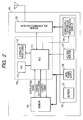
- FIG. 2 is a block diagram of a node 100 installed in a hydrogen gas station 10 of FIG. 1.
- the node 100 is composed of a node control unit (microcomputer) 110, a wireless communicationmodule (wireless transceiver) 120, a power supply unit 130, and a sensor unit 140.
- a node control unit microcomputer
- wireless communicationmodule wireless transceiver
- the node control unit 110 is composed of an MCU (micro controller) 111 as a core which controls overall operation of the node 100, a real time clock controller (RTC) 113, and other miscellaneous circuits 112.
- the node control unit (microcomputer) 110 has a communication control function to control wireless communication between the node 100 and the access point 200 under the control of the control program and an equipment control function to control the shut-off valves 5 under a command from the host device.
- the MCU 111 is usually placed in standby mode, controlled to minimize battery power consumption.
- Standby mode refers to the state when only the sensor operates.
- the MCU goes out of standby mode by an interrupt signal that is issued at given intervals from the RTC 113 or an interrupt signal that is issued from the sensor 140.
- the former interrupt signal is a regular communication signal and its main role is periodically reporting to the access point 200 that the node operates normally.
- the interval period of this signal can be set by DIPSW included in the miscellaneous circuits 112.
- the latter interrupt signal is issued by the sensor 140 when the sensor 140 detects an abnormal value of gas and is an important signal that acts as a trigger to report abnormality to the access point 200.
- the wireless module 120 is, for example, a wireless transceiver classified under the category of specified low power radio stations prescribed in Japanese Radio Law. It has transmitting and receiving functions and specifications, a communication range of 100 m and a communication rate of about 4800 bps. The specifications of this wireless module 120 are appropriately set, based on a region where the node is installed and local regulations. Moreover, the wireless module 120 has a function of allowing the operation switching one transmitting/receiving frequency band to another, a function of checking whether a radio frequency channel for transmission is idle, that is a carrier sense function. The control unit 110 can wirelessly communicate with the access point 200 via the wireless module 120.
- the power supply unit 130 is composed of a battery 131, a main power supply 132, a voltage monitor 133, and a power supply for wireless communication module 134. All the power for the node 100 is supplied from the battery 131.
- the power supply separates into two paths, a first power supply path to supply power from the battery 131 via the main power supply 132 to the control unit 110 and the sensor 140 and a second power supply path to supply power from the battery 131 via the power supply for wireless communication module 134 to the wireless communication module 120.
- the first power supply path always supplies power.
- the second power supply path is configured so that it can be on/off controlled from the MUC 111 and is controlled to be on only when wireless communication takes place via the wireless communication module 120.
- the voltage monitor 133 has a function to notify the control unit of how the battery is consumed and is used in particular when information of remaining battery power is communicated to the access point.
- a hydrogen sensor is mounted on the sensor 140.
- the hydrogen sensors detect a hydrogen concentration in atmospheric air reaching about 100 PPM or higher as an abnormal value.
- the sensor 140 and the MCU 111 are connected by three lines: a line over which an interrupt signal Int is sent and received; a line over which sensor output Sout, an analog voltage representing a sensed value is sent and received; and a line over which a control signal Cs to control the sensor is sent and received.
- the control signal Cs is used to switch one measurement mode of the hydrogen sensor to another in this embodiment. More specifically, this signal is used to switch between a mode in which high precision hydrogen measurements are made with more power consumed and a mode in which rough measurements are made with low power.
- the node 100 of this embodiment is used for the purpose of detecting hydrogen gas, it is designed so that it can control the shut-off valves on the piping by a command wirelessly received from the access point by replacing the hydrogen sensor that is attached to the sensor 140 unit with a valve open/close control module.
- FIG. 3 is a block diagram of the access point 200 installed in the hydrogen station 10 involved in the present invention.
- the access point is composed of the following interconnected elements: a power supply 240; a large-capacity storage device (HDD) 250; a CTRBOX 210 having a function equivalent to a computer for control; and a wireless transmitter module RFMA 220 and a wireless receiver module 230 which have functions equivalent to the wireless communication module 120.
- a power supply 240 a large-capacity storage device (HDD) 250
- CTRBOX 210 having a function equivalent to a computer for control
- RFMA 220 and a wireless receiver module 230 which have functions equivalent to the wireless communication module 120.
- a microcomputer 211 is built in the CTRBOX 210 and a memory 212 is connected to its memory bus, while an HDD controller 213, a USB controller 214, and an Ethernet controller 215 are connected to the PCI bus (Ethernet is a registered trademark of Xerox Corporation).
- the microcomputer 211 in the CTRBOX 210 has a communication control function to control wireless communication between each node 100 and the access point 200 and wired communication between the access point 200 and the terminal 1 under the control of the control program and an equipment control function to make each node 100 control the shut-off valves 5.
- Linux is installed on the access point 200 for control of the HDD controller 213, USB controller 214, and Ethernet controller 215 and other control tasks, and web server, database, and other applications can run on it.
- FIG. 4 depicts wireless connections between each node 100 and the access point 200.
- Wireless communications between each node 100 and the access point 200 are performed using a node control channel 300 and a transmission channel from node 301.
- Separate radio frequencies are assigned to the channels 300 and 301 so that both radio channels and frequency bands do not interfere with each other. That is, a radio frequency f1 of the channel 300 and a radio frequency f2 of the channel 301 are different. If a plurality of access points 200 are installed in each hydrogen gas station 10, separate frequencies are assigned to both channels per access point 200.
- Each node 100 performs communication, using the channel 300 for receiving only and the channel 301 for transmitting only.
- the communication includes a regular reporting mode to report the status of each node 100 at intervals of about one hour and an abnormal reporting mode to report the status of each nod 100 upon the occurrence of abnormality.
- the transmitting channel 301 is shared across the plurality of nodes , especially when two or more nodes transmit at the same time during the abnormal reporting mode, a communication collision occurs and makes correct information transmission impossible.
- each node checks whether the channel over which it will transmit is idle by carrier sensing before transmission and initiates communication at timing to avoid a collision as much as possible.
- control to avoid a collision between transmissions from a plurality of nodes is generally called CSMA/CA.
- Carrier sense refers to a means for detecting whether a radio frequency band is being used.
- the receiving channel 300 is shared across the plurality of nodes as is the case for the transmitting channel 301. However, because these nodes are controlled to entirely receive over this channel, this channel is free from a collision which would occur on the channel 301.
- the access point 200 includes the RFMA 220 and RFMB 230 wireless modules.
- the RFMA 220 and RFMB 230 are radio modules having identical specifications, but their roles are different.
- the RFMB 230 is used as a receiver only for the purpose of keeping monitoring the channel 301 over which warning is transmitted.
- the RFMA 220 is used as a carrier sensor to determine the busy ratio of the channel 301 and as a transmitter to transmit a packet in which the channel busy ratio is embedded onto the channel 300.
- the busy ratio of the channel 301 is derived from results obtained by detecting whether a carrier (the dotted circle 302) is present on the channel 301 repeatedly at given intervals.
- the RFMA 220 also has a function to transmit one of various commands that may be generated in the CTRBOX 210 in accordance with a request received over the wired network 303 or a result received by the RFMB 230 onto the channel 300.
- FIG. 5 shows the structure of a packet that is transmitted and received by communication between each node 100 and the access point 200.
- the packet 350 is made up of the following fields: receiver identifier 351 to identify the receiver of the packet; sender identifier 352 to identify the sender of the packet; channel busy ratio 353 in which the channel busy ratio of the channel 301 is stored; command type 354 specifying a command issued to the receiving node; argument 355 in which an argument of the command is stored.
- the command type 354 field contains one of different commands to request various actions. Specifically, the following commands are defined. “continue” - Continue monitoring. Report the status again after the elapse of seconds specified by the argument. "standby” - Change to standby state. "battery” - Report the battery remaining power.
- FIG. 6 shows a flowchart of operation of the access point that determines the busy ratio of the transmission channel from node and transmits this information onto the node control channel. Using this figure, a method of deriving the busy ratio of the channel 301 by the microcomputer on the access point 200 and the flow of transmitting the busy ratio onto the channel 300 will be explained.
- a variable U representing the busy ratio is initialized to 0 (S601).
- U assumes a value in a range from 0 to 100 which is the greatest busy ratio.
- the next decision step determines whether to measure the channel busy ratio (S604).
- the channel busy ratio is measured 10 times per second, i.e., at intervals of about 100 ms. This decision determines whether 100 ms has passed after the last measurement of the channel busy ratio. If this decision is true, an NOP packet is generated (S605).
- the NOP packet is defined as follows: a packet in which "nop" (no operation) is specified in the command type 354 field and a node that received this packet does no action other than copying the value contained in the channel busy ratio 353 field into the node's memory.
- sensing the carrier 302 shown in FIG. 4 is performed and a successful result is the carrier sensed CS (S611).
- a new channel busy ratio U is derived by adding the carrier sensed CS to the previous channel busy ratio U multiplied by 0.9, as in an equation below. If the carrier sensed is added, a constant of 10 is used; if no carrier has been sensed, a constant of 0 is used (S612 to S615).
- U U ⁇ 0.9 + 10 ⁇ C S
- the access point 200 stores the value of U derived by the algorithm (S610) into the channel busy ratio 353 field in the packet (S620) and transmits the packet onto the channel 300 (S621), thus notifying each node 100 of the busy ratio of the channel 301.
- a series of operations described above is performed by using the wireless module RFMA 220 on the access point 200.
- nodes 100 in the vicinity of the leakage location start to transmit warning to the access point all at once, signaled by the sensors 140 mounted on the nodes.
- FIG. 7 is a flowchart of operation of a node that controls transmission, using the value sensed by the sensor 140 and the channel busy ratio. Using FIG. 2 and FIG. 7, this flowchart will be explained in detail.
- the sensor 140 on the node 100 generates an interrupt when it detects gas leakage (S700), which activates the MCU 111 of the microcomputer.
- the MCU 11 Upon being activated, the MCU 11 initializes the program (S701), and the procedure goes to the entry to decision (S702).
- S703 In preparation for transmission, receiving a packet 350 transmitted on the radio channel 300 is tried and information L sensed by the sensor is obtained (S703). That is, the node 100 gets the concentration of hydrogen gas leaked from the sensor 140.
- the concentration value is normalized to a hydrogen concentration level L in the range from 0 to 100.
- the node 100 turns on the power supply for wireless communication module 134 and activates the wireless communication module 120.
- the node 100 receives the packet transmitted on the channel 300, gets the channel busy ratio U of the channel 301 from the channel busy ratio 353 field of the packet, and normalizes it to a channel busy ratio R in the range from 0 to 100 (S704).
- the node determines whether to transmit (S705), based on a criterion pattern for transmission decision which is given in advance.
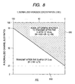
- FIG. 8 shows an example of the criterion pattern for transmission decision 800 by which transmission is controlled, or whether to transmit is determined, based on the hydrogen concentration level L and the channel busy ratio R.
- the ordinate represents normalized channel busy ratio R and the abscissa represents normalized hydrogen concentration level L.
- Normalized values R and L fall within the range from 0 to 100; the greater the value, the higher will be the channel busy ratio or the hydrogen concentration level.
- values of 20% and below absolutely fall in a region 810 in the light of the fact that the need for limiting channel use is reduced in the low region of channel busy ratio R.
- values of 95% and above absolutely fall in a region 820, because, when the channel busy ratio R is seriously high, still giving the node the chance of using the channel increases confusion and such status is hard to control. In this case, transmission from the node is deferred to wait until the channel busy ratio R decreases less than 95%.
- step of determining whether to transmit S705 if the point at which L and R meet falls within the region 810, it is regarded as true; if the point falls within the region 820, it is regarded as false. If the result of the decision is true, the procedure goes to the transmission flow (S706) and the node is controlled to transmit after the elapse of D milliseconds. If, on the other hand, the result of the decision is false, transmission from the node is deferred (S707) and it is determined again whether to transmit after the elapse of W milliseconds.
- Time periods to wait are used for the purpose of deliberately shifting transmission timing so that a plurality of nodes do not start to transmit synchronously at the same time.
- the criterion pattern for transmission decision 800 of FIG. 8 is just one example and its form is not so limited.
- the line separating the criterion pattern for transmission decision 800 into two regions may be set appropriately as a function f (R, L) for channel busy ratio R and hydrogen concentration level L or a function including another element added to R and L.
- the procedure goes to the transmission flow (S706) and, after a wait for the time (D millisecond) described in FIG. 8, goes to a carrier sense step (S711).
- the node checks whether the channel 301 is idle by carrier sending and performs transmission. If the channel is busy, the node repeats carrier sensing several times until the channel becomes idle. If the channel is still busy, the procedure goes to an error processing routing, which is not shown in FIG. 7, and appropriate processing is performed.
- the access point Having received transmission from the node, the access point transmits a packet onto the channel 300 to notify the sender node that receiving has been done properly.
- the node receives the packet (S712), interprets the command in the packet (S720), and executes the action specified in the command type 354 field within the packet (S721).
- the node waits for time (S723) specified in the argument 355 field within the packet and then returns to the entry to decision (S702) to measure the hydrogen concentration again and determine whether to transmit to the access point. If the command type 354 field contains "standby,” this command is issued from the access point when the report is erroneous or when the leakage has already been calmed and recovery of safety verified. When having received this command, the node changes to standby mode (S724). Moreover, there is a special command that requests a return of the result of the command execution to the access point, like "battery" specified in the command type 354 field.
- the node Having received this command, the node measures the battery remaining power, returns to the beginning of the transmission flow (S706), and transmits that information to the access point (S711). Otherwise, if an error or receiving timeout occurs, the node returns to the beginning of the transmission flow (S706) and executes retransmission.
- abnormality information from the node is forwarded from the access point 200 to the terminal 1 at the supervisory center or the like connected to the Internet.
- personnel at the supervisory center estimates the gas leakage and directs the hydrogen gas station that necessary countermeasures should be taken or notifies the departments concerned of the gas leakage.
- the estimation of the gas leakage location is performed, based on information from the sensors detecting higher concentration gas, if the capacity of the communication channel is finite, the transmissions from the sensors detecting lower concentration gas are deferred, so that information from the sensors detecting higher concentration gas will be more likely to arrive at an access point.
- FIG. 9 is a table listing the specific gravities of fuel gasses relative to air.
- Gasoline, butane, and propane tend to settle down because they are heavier than air, whereas natural gas and hydrogen tend to diffuse upward because they are lighter than air.
- hydrogen is highly diffusive as its specific gravity is one fourteenth of air.
- hydrogen gas stations now in practical use hydrogen gas is stored, compressed at as high pressure as 35 MPascal and charged into vehicles by pressure difference. Furthermore, hydrogen gas is said to be compressed at higher pressure up to 70 to 90 MPascal in future, because it is required to increase continuous mileage of vehicles powered by hydrogen.
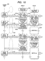
- FIG. 10 shows an example of how a plurality of nodes and the access point operate in emergency.
- FIG. 10 describes the operations of a fifth closest node to the leakage location (node A) and a tenth closest node to the leakage location (node B) among the plurality of nodes installed. Operation steps (S700 to S707) described in FIG. 10 correspond to the operation steps (S700 to S707) in FIG. 7.
- the access point 200 performs carrier sensing on the channel 301 at give intervals, derives the channel busy ratio U, embeds it into a packet, and transmit the packet onto the channel 300. Transmission of the channel busy ratio is always output at given intervals, regardless of whether or not hydrogen leakage occurs.
- the sensors detect abnormality and the nodes transmit the abnormality to the access point in order of closest to the leakage location.
- the node A detects the hydrogen leakage, the nodes closer to the leakage location has already transmitted the abnormality and, thus, the channel busy ratio U for communication is 45.
- the node A detects the gas leakage, obtains the channel busy ratio R and the hydrogen concentration level L, and determines whether to transmit for transmission control, according to the flowchart of FIG. 7.
- the node A After the transmission, the node A receives a "continue" command which commands the node to continue monitoring. Thus, it reports the sensed hydrogen concentration again after the elapse of a given time.
- the node B the tenth closest one to the leakage location, also detects the hydrogen gas leakage.
- the same operations take place, according to the flowchart of FIG. 7.
- W 1250 milliseconds.
- gas leakage in a hydrogen gas station is detected quickly and proper communication in which priority is given to more urgent transmissions can be ensured. Consequently, hydrogen can be utilized more safely.
- the number of sensors whose sensed information should be transmitted can be controlled dynamically depending on the channel status and, therefore, logically, an infinite number of sensors can be placed in one hydrogen station.
- hydrogen gas leakage can be detected with high precision and reliably and hydrogen gas stations can be installed in an urban area or the like where high safety is required. A great number of sensors can be installed in a hydrogen gas station at low cost.
- the hydrogen gas station of the present embodiment is provided with a set of functions including detecting gas leakage quickly, notifying the manager of danger, and shutting off the gas at the main valve and allows for safe utilization of hydrogen.
- first embodiment the method of controlling transmissions according to hydrogen concentration information provided from the sensors and the channel busy ratio has been described.
- second embodiment an instance where transmissions are controlled, using only hydrogen concentration levels provided from the sensors, without using the channel busy ratio, is described.
- FIG. 11 shows a flowchart of operation of a node that controls transmission, using only hydrogen concentration levels. The steps except those denoted by S1000 are the same as described in FIG. 7 and, therefore, their explanation is not repeated.
- a part of the procedure denoted by S1000 is a general CSMA/CA control flow that is used for wireless LANs and the like. Only difference is that carrier sensing time C changes according to the obtained hydrogen concentration level in step S1001. Carrier sensing time C is set smaller for nodes detecting higher concentration hydrogen.
- Second embodiment is a means that is effective for a hydrogen gas station where the number of hydrogen sensors installed is fewer than in first embodiment and the channel has a sufficient capacity.
- gas leakage in a hydrogen gas station is detected quickly and proper communication in which priority is given to more urgent transmissions can be ensured. Consequently, hydrogen can be utilized more safely and hydrogen gas stations can be installed in an urban area or the like where high safety is required.
- the present invention can be similarly applied to hydrogen gas stations oriented to hydrogen gas vehicles equipped with an internal combustion engine in which hydrogen gas from the high-pressure container storing the hydrogen gas is combusted, instead of fuel-cell vehicles.
- the present invention is not limited to hydrogen gas stations, and can be applied broadly to installations that handle gas like hydrogen and natural gas, which will diffuse very quickly and may explode if leakage is neglected.
Landscapes
- Business, Economics & Management (AREA)
- General Physics & Mathematics (AREA)
- Physics & Mathematics (AREA)
- Emergency Management (AREA)
- Engineering & Computer Science (AREA)
- Environmental & Geological Engineering (AREA)
- Toxicology (AREA)
- General Health & Medical Sciences (AREA)
- Chemical & Material Sciences (AREA)
- Health & Medical Sciences (AREA)
- Combustion & Propulsion (AREA)
- Computer Networks & Wireless Communication (AREA)
- Alarm Systems (AREA)
- Mobile Radio Communication Systems (AREA)
- Emergency Alarm Devices (AREA)
- Data Exchanges In Wide-Area Networks (AREA)
- Selective Calling Equipment (AREA)
- Arrangements For Transmission Of Measured Signals (AREA)
Applications Claiming Priority (1)
| Application Number | Priority Date | Filing Date | Title |
|---|---|---|---|
| JP2004342242A JP3945714B2 (ja) | 2004-11-26 | 2004-11-26 | ガス漏洩検知機能付き無線端末及びそれを用いたガス漏洩検知システム及びガス漏洩通報方法 |
Publications (2)
| Publication Number | Publication Date |
|---|---|
| EP1662455A2 true EP1662455A2 (de) | 2006-05-31 |
| EP1662455A3 EP1662455A3 (de) | 2006-08-16 |
Family
ID=35840473
Family Applications (1)
| Application Number | Title | Priority Date | Filing Date |
|---|---|---|---|
| EP20050254304 Withdrawn EP1662455A3 (de) | 2004-11-26 | 2005-07-08 | Drahtloses Endgerät zur Detektion von Gaslecken, dazu gehöriges Gasleckdetektionssystem, und Gasleck-Anzeigemethode |
Country Status (3)
| Country | Link |
|---|---|
| US (1) | US7345590B2 (de) |
| EP (1) | EP1662455A3 (de) |
| JP (1) | JP3945714B2 (de) |
Cited By (4)
| Publication number | Priority date | Publication date | Assignee | Title |
|---|---|---|---|---|
| NO20151215A1 (en) * | 2015-09-17 | 2017-03-20 | Vks Alarm Og Sikkerhet As | Gas Leak Alarm System |
| CN110088608A (zh) * | 2016-12-15 | 2019-08-02 | 松下知识产权经营株式会社 | 氢检测装置、燃料电池汽车、氢泄漏监视系统、复合传感器模块、氢检测方法以及程序 |
| CN110741708A (zh) * | 2017-11-03 | 2020-01-31 | Oppo广东移动通信有限公司 | D2d通信中载波选取的方法和终端设备 |
| CN111899480A (zh) * | 2020-08-11 | 2020-11-06 | 安徽泽众安全科技有限公司 | 一种地下空间可燃气体监测动态预警分级方法及系统 |
Families Citing this family (32)
| Publication number | Priority date | Publication date | Assignee | Title |
|---|---|---|---|---|
| US10368146B2 (en) | 2016-09-20 | 2019-07-30 | General Electric Company | Systems and methods for environment sensing |
| US20080128453A1 (en) * | 2006-11-30 | 2008-06-05 | Flint Loc Security Llc | Dispenser security system |
| US7343251B1 (en) * | 2007-01-31 | 2008-03-11 | Toyota Motor Engineering & Manufacturing North America, Inc. | Method to detect a hydrogen leak in a fuel cell |
| KR101580325B1 (ko) * | 2009-07-01 | 2015-12-23 | 삼성전자주식회사 | 피코넷 마스터 노드 온/오프 스케줄링을 위한 프레임 구조 및 그 방법 |
| US20120188916A1 (en) * | 2009-09-30 | 2012-07-26 | Eiji Miyake | Wireless device, wireless apparatus using same, and wireless system |
| WO2012114738A1 (ja) * | 2011-02-22 | 2012-08-30 | パナソニック株式会社 | 無線通信システムとそれに用いられる無線子機及び無線親機 |
| JP2012227864A (ja) * | 2011-04-22 | 2012-11-15 | Japan Radio Co Ltd | 通信ノード |
| US8606258B2 (en) * | 2011-12-21 | 2013-12-10 | Silver Spring Networks, Inc. | System and method for integrated metrology within a femtocell access point |
| US20130201025A1 (en) * | 2012-02-07 | 2013-08-08 | Arunkumar Kamalakannan | Method of Monitoring a Gas Leakage Incident |
| CN102607771B (zh) * | 2012-02-23 | 2014-07-09 | 中山大学 | 一种氢气泄漏在线检测的仿真方法及系统 |
| KR20140000010A (ko) | 2012-06-22 | 2014-01-02 | 삼성전자주식회사 | 반도체 메모리 장치 |
| JP5931644B2 (ja) * | 2012-08-17 | 2016-06-08 | 株式会社東芝 | 充電管理システム |
| JP6273723B2 (ja) * | 2013-09-02 | 2018-02-07 | 株式会社国際電気通信基礎技術研究所 | 無線通信システムおよびセンサ装置 |
| JP6395201B2 (ja) * | 2013-11-26 | 2018-09-26 | 住友電気工業株式会社 | 管理装置、通信システム、無線端末装置、通信制御方法および通信制御プログラム |
| US9858803B2 (en) * | 2015-08-12 | 2018-01-02 | Honeywell International Inc. | Gas detectors safety compliance advertisement via low-power wireless radio |
| US10617985B2 (en) | 2016-09-29 | 2020-04-14 | Rosemount Inc. | Gas sensor module with field replaceable, ingress protected, sensor filter |
| US10317295B2 (en) | 2016-09-30 | 2019-06-11 | Rosemount Inc. | Heat flux sensor |
| KR102398842B1 (ko) * | 2017-03-23 | 2022-05-17 | 삼성전자 주식회사 | 무선 통신 시스템에서 무선 경로 변경 방법 및 장치 |
| KR20180120521A (ko) * | 2017-04-27 | 2018-11-06 | 한라아이엠에스 주식회사 | 플로우 밸런싱을 이용한 가스의 분석장치의 분석시간 단축시스템 |
| US11268459B2 (en) | 2017-12-28 | 2022-03-08 | Gas Activated Systems, Inc. | Fugitive gas detection system |
| US11661896B2 (en) | 2017-05-15 | 2023-05-30 | Gas Activated Systems | Engine overspeed device and method |
| US10976204B2 (en) | 2018-03-07 | 2021-04-13 | Rosemount Inc. | Heat flux sensor with improved heat transfer |
| CN108245918B (zh) * | 2018-03-21 | 2023-07-14 | 南京工业大学 | 基于气体监测和声发射技术的半导体多晶硅精馏塔开裂自动报警器 |
| CN108629949A (zh) * | 2018-06-29 | 2018-10-09 | 上海美桥科材料科技有限公司 | 易燃易爆有毒有害气体监测报警系统及应急方法 |
| EP3857189B1 (de) | 2018-09-28 | 2025-01-15 | Rosemount Inc. | Nichtinvasive prozessflüssigkeitstemperaturanzeige mit reduzierter fehleranfälligkeit |
| US12072269B2 (en) | 2019-03-29 | 2024-08-27 | Rosemount Inc. | Self-contained calibration apparatus for gas sensor |
| US11725966B2 (en) | 2020-09-18 | 2023-08-15 | Rosemount Inc. | Multi-stage irreversible sensor coupling |
| CN114727248B (zh) * | 2020-12-22 | 2025-01-21 | 中国石油化工股份有限公司 | 高危作业气体监控方法、终端及系统和报警方法及报警仪 |
| JP7703406B2 (ja) * | 2021-09-10 | 2025-07-07 | 能美防災株式会社 | 無線機 |
| CN114038179B (zh) * | 2021-11-05 | 2023-09-01 | 北京金山云网络技术有限公司 | 一种燃气报警方法、装置、电子设备及存储介质 |
| EP4202881A1 (de) * | 2021-12-23 | 2023-06-28 | Volvo Truck Corporation | Alarmsystem und verfahren zur detektion von gasleckage aus einem fahrzeug |
| CN118587850B (zh) * | 2024-06-07 | 2025-02-11 | 济南鼎诺科技有限公司 | 一种可燃气体报警控制系统及方法 |
Family Cites Families (9)
| Publication number | Priority date | Publication date | Assignee | Title |
|---|---|---|---|---|
| JP3180500B2 (ja) | 1993-03-01 | 2001-06-25 | ヤマハ株式会社 | リアルタイム通信用バス型lan |
| JPH0846633A (ja) | 1994-07-26 | 1996-02-16 | Toyo Techno Corp:Kk | データ通信装置 |
| JP3184429B2 (ja) * | 1995-06-30 | 2001-07-09 | ホーチキ株式会社 | 防災監視システムの端末感知装置 |
| JPH10320675A (ja) | 1997-05-16 | 1998-12-04 | Matsushita Electric Ind Co Ltd | 無線警報システム |
| JPH11306463A (ja) | 1998-04-20 | 1999-11-05 | Fuji Electric Co Ltd | ガス漏れ警報器 |
| US6252510B1 (en) * | 1998-10-14 | 2001-06-26 | Bud Dungan | Apparatus and method for wireless gas monitoring |
| US6794991B2 (en) * | 1999-06-15 | 2004-09-21 | Gastronics′ Inc. | Monitoring method |
| JP2001077819A (ja) | 1999-09-01 | 2001-03-23 | Toyo Commun Equip Co Ltd | アドレス解決方法及び装置 |
| US7020562B2 (en) * | 2003-03-31 | 2006-03-28 | Proton Energy Systems, Inc. | Method of monitoring the operation of gas sensor and system therefor |
-
2004
- 2004-11-26 JP JP2004342242A patent/JP3945714B2/ja not_active Expired - Fee Related
-
2005
- 2005-07-08 EP EP20050254304 patent/EP1662455A3/de not_active Withdrawn
- 2005-07-15 US US11/181,928 patent/US7345590B2/en not_active Expired - Fee Related
Cited By (7)
| Publication number | Priority date | Publication date | Assignee | Title |
|---|---|---|---|---|
| NO20151215A1 (en) * | 2015-09-17 | 2017-03-20 | Vks Alarm Og Sikkerhet As | Gas Leak Alarm System |
| NO342227B1 (en) * | 2015-09-17 | 2018-04-23 | Vks Alarm Og Sikkerhet As | Gas Leak Alarm System |
| CN110088608A (zh) * | 2016-12-15 | 2019-08-02 | 松下知识产权经营株式会社 | 氢检测装置、燃料电池汽车、氢泄漏监视系统、复合传感器模块、氢检测方法以及程序 |
| CN110088608B (zh) * | 2016-12-15 | 2021-06-08 | 新唐科技日本株式会社 | 氢检测装置、燃料电池汽车、氢泄漏监视系统、复合传感器模块、氢检测方法以及程序记录介质 |
| CN110741708A (zh) * | 2017-11-03 | 2020-01-31 | Oppo广东移动通信有限公司 | D2d通信中载波选取的方法和终端设备 |
| CN110741708B (zh) * | 2017-11-03 | 2021-01-12 | Oppo广东移动通信有限公司 | D2d通信中载波选取的方法和终端设备 |
| CN111899480A (zh) * | 2020-08-11 | 2020-11-06 | 安徽泽众安全科技有限公司 | 一种地下空间可燃气体监测动态预警分级方法及系统 |
Also Published As
| Publication number | Publication date |
|---|---|
| US7345590B2 (en) | 2008-03-18 |
| US20060114114A1 (en) | 2006-06-01 |
| EP1662455A3 (de) | 2006-08-16 |
| JP3945714B2 (ja) | 2007-07-18 |
| JP2006157248A (ja) | 2006-06-15 |
Similar Documents
| Publication | Publication Date | Title |
|---|---|---|
| US7345590B2 (en) | Wireless terminal with gas leakage detection function, gas leakage detection system using the same, and gas leakage notification method | |
| US10861316B2 (en) | Relaying communications in a wireless sensor system | |
| US9000728B2 (en) | Vehicular electric charge control apparatus and emergency notification system | |
| US10895885B2 (en) | Universal remote machinery monitor | |
| US7102504B2 (en) | Wireless sensor monitoring unit | |
| US7583198B2 (en) | Method and apparatus for detecting water leaks | |
| WO2021059294A1 (en) | A system and method for managing a battery pack | |
| KR101926196B1 (ko) | 병렬 팩 배터리 시스템의 장애 관리 장치 및 그 방법 | |
| US11661079B2 (en) | Method for reducing the potential hazard in road traffic | |
| US20050275530A1 (en) | Wireless sensor system | |
| US20150298565A1 (en) | Charging support system and charging support method for electric vehicle | |
| EP4214789A1 (de) | Systeme zur detektion von thermischem durchgehen für batterien in gehäusen und verfahren zur verwendung davon | |
| US20050262923A1 (en) | Method and apparatus for detecting conditions favorable for growth of fungus | |
| WO2005119609A2 (en) | Wireless sensor system | |
| WO2007035219A1 (en) | Programmed wireless sensor system | |
| JP4082428B2 (ja) | 緊急通報装置及びシステム | |
| KR101632560B1 (ko) | 유류 관리 정보 전송 시스템 및 그 방법 | |
| EP3547483B1 (de) | Systeme und verfahren zur verwaltung von elektrisch betriebenen transportkühleinheiten etru | |
| KR102371424B1 (ko) | Bms를 기반으로 하는 차량 통합관리시스템 | |
| US12561637B2 (en) | Hydrogen monitoring apparatus and hydrogen management system | |
| KR101737421B1 (ko) | 이동식 보안서버를 이용한 원격 보안 시스템 | |
| KR102414002B1 (ko) | 독립모듈형 비상대피 인디케이팅 시스템 및 방법 | |
| US9716517B1 (en) | Intrinsically safe telematic systems | |
| JP2002112364A (ja) | 情報通信方法 | |
| KR20260004621A (ko) | 안전성 향상을 위한 이동식 모빌리티 배터리 관리 시스템 |
Legal Events
| Date | Code | Title | Description |
|---|---|---|---|
| PUAI | Public reference made under article 153(3) epc to a published international application that has entered the european phase |
Free format text: ORIGINAL CODE: 0009012 |
|
| AK | Designated contracting states |
Kind code of ref document: A2 Designated state(s): AT BE BG CH CY CZ DE DK EE ES FI FR GB GR HU IE IS IT LI LT LU LV MC NL PL PT RO SE SI SK TR |
|
| AX | Request for extension of the european patent |
Extension state: AL BA HR MK YU |
|
| PUAL | Search report despatched |
Free format text: ORIGINAL CODE: 0009013 |
|
| AK | Designated contracting states |
Kind code of ref document: A3 Designated state(s): AT BE BG CH CY CZ DE DK EE ES FI FR GB GR HU IE IS IT LI LT LU LV MC NL PL PT RO SE SI SK TR |
|
| AX | Request for extension of the european patent |
Extension state: AL BA HR MK YU |
|
| AKX | Designation fees paid |
Designated state(s): DE FR GB IT |
|
| STAA | Information on the status of an ep patent application or granted ep patent |
Free format text: STATUS: THE APPLICATION IS DEEMED TO BE WITHDRAWN |
|
| 18D | Application deemed to be withdrawn |
Effective date: 20070217 |