EP1661769B1 - Kniestütze für Kraftfahrzeuge - Google Patents
Kniestütze für Kraftfahrzeuge Download PDFInfo
- Publication number
- EP1661769B1 EP1661769B1 EP04257356A EP04257356A EP1661769B1 EP 1661769 B1 EP1661769 B1 EP 1661769B1 EP 04257356 A EP04257356 A EP 04257356A EP 04257356 A EP04257356 A EP 04257356A EP 1661769 B1 EP1661769 B1 EP 1661769B1
- Authority
- EP
- European Patent Office
- Prior art keywords
- transverse member
- knee restraint
- knee
- occupant
- impact
- Prior art date
- Legal status (The legal status is an assumption and is not a legal conclusion. Google has not performed a legal analysis and makes no representation as to the accuracy of the status listed.)
- Expired - Lifetime
Links
- 210000003127 knee Anatomy 0.000 title claims abstract description 71
- 230000002787 reinforcement Effects 0.000 claims abstract description 19
- 239000006260 foam Substances 0.000 claims description 20
- 239000000463 material Substances 0.000 claims description 9
- 239000004033 plastic Substances 0.000 claims description 6
- 229920003023 plastic Polymers 0.000 claims description 6
- 229910052751 metal Inorganic materials 0.000 claims description 4
- 239000002184 metal Substances 0.000 claims description 4
- 208000027418 Wounds and injury Diseases 0.000 description 6
- 230000006378 damage Effects 0.000 description 6
- 208000014674 injury Diseases 0.000 description 6
- 238000005452 bending Methods 0.000 description 4
- 239000004619 high density foam Substances 0.000 description 4
- 239000004620 low density foam Substances 0.000 description 4
- 239000011777 magnesium Substances 0.000 description 3
- FYYHWMGAXLPEAU-UHFFFAOYSA-N Magnesium Chemical compound [Mg] FYYHWMGAXLPEAU-UHFFFAOYSA-N 0.000 description 2
- 229910000831 Steel Inorganic materials 0.000 description 2
- 239000004411 aluminium Substances 0.000 description 2
- 229910052782 aluminium Inorganic materials 0.000 description 2
- XAGFODPZIPBFFR-UHFFFAOYSA-N aluminium Chemical compound [Al] XAGFODPZIPBFFR-UHFFFAOYSA-N 0.000 description 2
- 229910052749 magnesium Inorganic materials 0.000 description 2
- 210000004197 pelvis Anatomy 0.000 description 2
- 239000010959 steel Substances 0.000 description 2
- 210000002303 tibia Anatomy 0.000 description 2
- 210000000689 upper leg Anatomy 0.000 description 2
- 238000003466 welding Methods 0.000 description 2
- 238000010521 absorption reaction Methods 0.000 description 1
- 230000002411 adverse Effects 0.000 description 1
- 238000010276 construction Methods 0.000 description 1
- 238000006073 displacement reaction Methods 0.000 description 1
- 238000005516 engineering process Methods 0.000 description 1
- 230000001747 exhibiting effect Effects 0.000 description 1
- 239000006261 foam material Substances 0.000 description 1
- 210000004394 hip joint Anatomy 0.000 description 1
- 210000002414 leg Anatomy 0.000 description 1
- 238000004806 packaging method and process Methods 0.000 description 1
- 230000003014 reinforcing effect Effects 0.000 description 1
- 125000000391 vinyl group Chemical group [H]C([*])=C([H])[H] 0.000 description 1
- 229920002554 vinyl polymer Polymers 0.000 description 1
Images
Classifications
-
- B—PERFORMING OPERATIONS; TRANSPORTING
- B60—VEHICLES IN GENERAL
- B60R—VEHICLES, VEHICLE FITTINGS, OR VEHICLE PARTS, NOT OTHERWISE PROVIDED FOR
- B60R21/00—Arrangements or fittings on vehicles for protecting or preventing injuries to occupants or pedestrians in case of accidents or other traffic risks
- B60R21/02—Occupant safety arrangements or fittings, e.g. crash pads
- B60R21/04—Padded linings for the vehicle interior ; Energy absorbing structures associated with padded or non-padded linings
- B60R21/045—Padded linings for the vehicle interior ; Energy absorbing structures associated with padded or non-padded linings associated with the instrument panel or dashboard
-
- B—PERFORMING OPERATIONS; TRANSPORTING
- B60—VEHICLES IN GENERAL
- B60R—VEHICLES, VEHICLE FITTINGS, OR VEHICLE PARTS, NOT OTHERWISE PROVIDED FOR
- B60R21/00—Arrangements or fittings on vehicles for protecting or preventing injuries to occupants or pedestrians in case of accidents or other traffic risks
- B60R2021/003—Arrangements or fittings on vehicles for protecting or preventing injuries to occupants or pedestrians in case of accidents or other traffic risks characterised by occupant or pedestian
- B60R2021/0039—Body parts of the occupant or pedestrian affected by the accident
- B60R2021/0051—Knees
Definitions
- the present invention relates to a knee restraint for a vehicle and in particular a knee restraint to support, guide and protect the knees of the front seat occupant's of a vehicle, more particularly a car, during a frontal collision.
- the resistance to deflection and rigidity of the left and right knee impact areas can vary due to different design shapes and structures of such regions of the instrument panel and glove box which are a function of the styling and packaging of the components as well as the components' properties.
- Such difference in resistance to deflection results in a difference in the deflection of the occupant's left and right knee during a frontal collision which can cause the occupant's head and torso to rotate, adversely affecting the occupant's safety and risk of injury.
- US 4,721,329 discloses a deformable knee bolster exhibiting positive knee capture by means of pocketing deformation of the knee bolster that occurs upon knee impact with the bolster. Such document does not address the problem of torso rotation.
- the transverse member is connectable to the vehicle body by means of a first support member at or adjacent a first side of the transverse member and a second support member at or adjacent a second side of the transverse member, the relative stiffness of the first and second support members being predetermined or selected to provide substantially equal deflection in the case of an impact by a respective left and right knee of a vehicle occupant, thereby preventing rotation of the occupant's body during impact with the knee restraint in the event of a collision.
- each of the first and second support members includes at least one notch, or cut-out, or other region of reduced material thickness or cross section in each support member, the stiffness of each of the first and second support members being determined by the size and/or shape of the notch or cut-out therein.
- the reinforcement means extends between the support members.
- the reinforcement means may be affixed to the support members.
- the transverse member includes a first layer of energy absorbing foam for absorbing the impact of the occupant's knees therewith.
- the reinforcement means may be affixed to or embedded within the first layer of energy absorbing foam.
- the reinforcement means comprises a second layer of foam having a greater stiffness and/or hardness and/or density than the first layer of foam.
- the first layer of foam has a density of between 30 and 60 g/l and the second layer of foam has a density of at least 100g/l.
- the reinforcement means comprises a sheet of rigid material.
- the sheet of rigid material may be formed from plastic or from a metal, such as steel, aluminium or magnesium.
- the reinforcement means may comprise a thin walled deformable structure to further improve energy absorbtion properties of the knee restraint.
- the support members are adapted to be deformable to absorb the impact of the occupant's knees with the knee restraint.
- the support members can be formed in different designs using different materials (Al, Steel, Mg, Plastic, etc.) and technologies (rolled formed, deep drawn, die cast, moulded, etc.).
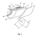
- Figure 1 shows a knee restraint according to a first embodiment of the present invention applied to a passenger car.
- the knee restraint is attached to a cross car beam 1 extending transversely across the width of the vehicle approximately between the A-pillars such that the knee restraint extends across the car in front of the occupant's knees 7 and beneath the instrument panel.
- the knee restraint is attached to the cross car beam 1 by means of two cantilevered support brackets 2 (only one side shown) provided adjacent each side of a transverse member 3.
- the support brackets 2 are located in the region of the left and the right knee impact line.
- the transverse member 3 defines a knee impact element formed from a first or inner layer of relatively rigid high density foam 3a (e.g. at least 100g/l foam density) providing a reinforcement means extending between the support brackets 2 to resist bending/displacement of the central region of the transverse member 3 and a second or outer layer of relatively low density foam 3b (e.g. 30-60 g/l foam density) intended to absorb the impact of the occupant's knees 7 therewith in the event of a frontal collision.
- relatively low density foam 3b it is possible to implement a deformable thin wall structure from plastic or metal (for example honeycomb structures).
- the outer layer of foam 3a would be covered by a skin or cover 5 of plastic or vinyl material, which might form part of the instrument panel or interior of the vehicle, or the knee restraint might be mounted behind the instrument panel or vehicle interior trim.
- the transverse member 3 extends across the steering column assembly 6, beneath the instrument panel. In the event of a frontal impact the knees 7 of the vehicle occupant impact the transverse member 3, the energy of such impact being at least partially absorbed by deformation of the outer layer of low density foam 3b.
- the first or inner layer of relatively rigid high density foam 3a resists deflection or bowing of the transverse member 3 in the unsupported region between the support brackets 2 which might otherwise lead or guide the occupant's knees towards the steering column assembly 6 which might lead to an increased risk of injury to the occupant.
- each of the cantilevered support brackets 2 is provided with a notch 2M adjacent the cross car beam 1 which creates a preferential bending point about which the brackets 2 can bend during impact of the occupant's knees 7 with the transverse member 3 to further absorb the energy of impact.
- the stiffness of the each bracket 2 can be varied or "tuned" to compensate for different forces applied to each side of the transverse member 3 by the occupant's right and left knee, to ensure that each side of the transverse member 3 deflects by an equal amount, thus avoiding potentially dangerous twisting of the occupant's torso which might otherwise occur if each side of the transverse member 3 was deformed by different amounts.
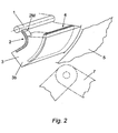
- the wall thickness, of the transverse member 3, the outer layer of low density foam 3b, the inner layer of relatively rigid high density foam 3a, as well as of the inlay 4 can be selected in each of the left and right knee impact areas to provide accordingly different system resistance and rigidity properties in each impact area.
- the reinforcement means reinforcing the transverse member 3 comprises a rigid sheet like inlay 4 of high density foam, plastic or metal (such as steel, aluminium or magnesium).
- the impact absorbing foam layer 3b is preferably integrally moulded with the inlay 4.
- the remainder of the knee restraint is identical in construction to that of the first embodiment and thus will not be described in more detail.
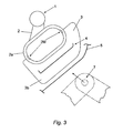
- the support brackets 2 are attached to the transverse member 3 by means of hollow deformable members 2a in the form of a closed loop having notches 2M on opposite inner sides thereof aligned normally to the expected direction of impact such that the resistance of the deformable members 2a to a crushing deformation can be selected to provide the desired degree of deformation such that the deformations of the support brackets 2 in response to impact of the right and left knees of the vehicle occupant in a frontal impact are equal to avoid rotation of the occupant's torso.
- the reinforcement means comprises a sheet of rigid material 4 embedded within the impact absorbing foam material 3b of the transverse member 3, said sheet 4 extending through the transverse member 3 between the support brackets 2 to resist deflection of the transverse member 3 in the region between the support brackets 2 which might cause the occupant's knees 7 to be guided towards the steering column assembly 6.
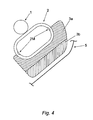
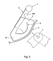
- the fourth embodiment shown in Figure 4 is similar to the third embodiment shown in Figure 3 , having a similar type of support bracket 2.
- the support brackets 2 may be attached to the cross car beam 1, for example by welding or fasteners, or may be formed integrally therewith.
- the main difference between the fourth embodiment and the third is that the reinforcement means preventing bending of the transverse member 3 is provided by a layer of higher density foam 3a sandwiched with the layer of low density energy absorbing foam 3b.
- the low density energy absorbing foam 3b needs to be reinforced (with either an inlay 4 or with a rigid foam component 3a) in order to prevent deflection of the transverse member in the region of the steering column assembly that would otherwise guide the occupant's knees towards the rigid structures of the steering column assembly because of the reduced wall thickness of the transverse member in the region of the steering column assembly.
- the proposed system optimally protects the vehicle front seat occupants, particularly the driver, during a frontal collision. Because tuning of the properties of the stiffness of the left and right knee impact areas is possible, the occupant's knees can be guided & supported in a controlled way, in correlation with the restraint system, in order to obtain a smooth driver motion during a collision, without dangerous body rotation.
Landscapes
- Engineering & Computer Science (AREA)
- Mechanical Engineering (AREA)
- Body Structure For Vehicles (AREA)
- Motorcycle And Bicycle Frame (AREA)
- Professional, Industrial, Or Sporting Protective Garments (AREA)
- Insulation, Fastening Of Motor, Generator Windings (AREA)
- Vibration Dampers (AREA)
Claims (13)
- Knierückhaltung für ein Fahrzeug, umfassend ein Querelement (3), das mit der Karosserie (1) des Fahrzeugs verbindbar ist, um in dem Gebiet unterhalb der Instrumententafel des Fahrzeugs vor den Knien (7) eines Insassen angeordnet zu werden, wobei das Querelement (3) mit der Fahrzeugkarosserie (1) über Stützelemente (2) verbindbar ist, die an oder benachbart jeder Seite des Querelementes (3) vorgesehen sind, wobei das Querelement (3) ein Aussteifungsmittel (4) umfasst, das in dem Gebiet zwischen den Stützelementen (2) vorgesehen ist, um einer Auslenkung des Querelements (3) in dem Gebiet entgegenzuwirken,
dadurch gekennzeichnet, dass
das Querelement (3) mit der Fahrzeugkarosserie (1) durch ein erstes Stützelement (2) an oder benachbart einer ersten Seite des Querelementes und ein zweites Stützelement an oder benachbart einer zweiten Seite des Querelementes verbindbar ist, wobei die relative Steifigkeit des ersten und zweiten Stützelementes (2) gewählt oder vorbestimmt ist, um in dem Fall eines Aufpralles durch ein jeweiliges linkes und rechtes Knie eines Fahrzeuginsassen eine im Wesentlichen gleiche Auslenkung bereitzustellen, wodurch eine Drehung des Körpers des Insassen während des Aufpralls mit der Knierückhaltung in dem Falle einer Kollision verhindert wird. - Knierückhaltung nach Anspruch 1,
wobei das Aussteifungsmittel (4) zwischen den Stützelementen (2) verläuft. - Knierückhaltung nach Anspruch 2,
wobei das Aussteifungsmittel (4) an den Stützelementen (2) befestigt ist. - Knierückhaltung nach einem der vorhergehenden Ansprüche,
wobei das Querelement (3) eine erste Schicht aus energieabsorbierendem Schaum (3b) zur Absorption des Aufpralls der Knie des Insassen damit umfasst. - Knierückhaltung nach Anspruch 4,
wobei das Aussteifungsmittel (4) an der ersten Schicht aus Schaum (3b) befestigt oder darin eingebettet ist. - Knierückhaltung nach einem der Ansprüche 4 oder 5,
wobei das Aussteifungsmittel (4) eine zweite Schicht aus Schaum (3a) besitzt, die eine größere Steifigkeit und/oder Härte und/oder Dichte besitzt, als die erste Schicht aus Schaum (3b). - Knierückhaltung nach Anspruch 6,
wobei die erste Schicht aus Schaum (3b) eine Dichte zwischen 30 und 60 g/l besitzt und die zweite Schicht aus Schaum (3a) eine Dichte von zumindest 100 g/l besitzt. - Knierückhaltung nach einem der Ansprüche 1 bis 5,
wobei das Aussteifungsmittel (4) eine Tafel aus starrem Material umfasst. - Knierückhaltung nach Anspruch 8,
wobei die Tafel aus starrem Material (4) aus Kunststoff oder einem Metall geformt ist. - Knierückhaltung nach einem der Ansprüche 1 bis 5,
wobei das Aussteifungsmittel (4) eine dünnwandige verformbare Struktur umfasst. - Knierückhaltung nach einem der vorhergehenden Ansprüche,
wobei die Stützelemente (2) derart ausgebildet sind, so dass sie verformbar sind, um den Aufprall der Knie (7) eines Insassen mit der Knierückhaltung zu absorbieren. - Knierückhaltung nach einem der vorhergehenden Ansprüche,
wobei jedes des ersten und zweiten Stützelementes (2) zumindest eine Kerbe, einen Ausschnitt oder ein anderes Gebiet mit reduzierter Materialdicke oder reduziertem Querschnitt (2M) aufweist, wobei die Steifigkeit von jedem des ersten und zweiten Stützelementes (2) durch die Größe und/oder Form der Kerbe oder des Ausschnittes (2M) darin bestimmt ist. - Knierückhaltung nach einem der vorhergehenden Ansprüche,
wobei die Wanddicke des Querelementes (3) in dem linken und rechten Knieaufprallbereich derart gewählt oder angepasst ist, um vorab gewählte Energieabsorptionseigenschaften und/oder eine vorabgewählte Steifigkeit bereitzustellen.
Priority Applications (3)
| Application Number | Priority Date | Filing Date | Title |
|---|---|---|---|
| AT04257356T ATE426527T1 (de) | 2004-11-26 | 2004-11-26 | Kniestutze fur kraftfahrzeuge |
| EP04257356A EP1661769B1 (de) | 2004-11-26 | 2004-11-26 | Kniestütze für Kraftfahrzeuge |
| DE602004020236T DE602004020236D1 (de) | 2004-11-26 | 2004-11-26 | Kniestütze für Kraftfahrzeuge |
Applications Claiming Priority (1)
| Application Number | Priority Date | Filing Date | Title |
|---|---|---|---|
| EP04257356A EP1661769B1 (de) | 2004-11-26 | 2004-11-26 | Kniestütze für Kraftfahrzeuge |
Publications (2)
| Publication Number | Publication Date |
|---|---|
| EP1661769A1 EP1661769A1 (de) | 2006-05-31 |
| EP1661769B1 true EP1661769B1 (de) | 2009-03-25 |
Family
ID=34930848
Family Applications (1)
| Application Number | Title | Priority Date | Filing Date |
|---|---|---|---|
| EP04257356A Expired - Lifetime EP1661769B1 (de) | 2004-11-26 | 2004-11-26 | Kniestütze für Kraftfahrzeuge |
Country Status (3)
| Country | Link |
|---|---|
| EP (1) | EP1661769B1 (de) |
| AT (1) | ATE426527T1 (de) |
| DE (1) | DE602004020236D1 (de) |
Families Citing this family (1)
| Publication number | Priority date | Publication date | Assignee | Title |
|---|---|---|---|---|
| JP6065525B2 (ja) * | 2012-11-06 | 2017-01-25 | 三菱自動車工業株式会社 | 車両の膝衝突保護構造 |
Family Cites Families (7)
| Publication number | Priority date | Publication date | Assignee | Title |
|---|---|---|---|---|
| US3929948A (en) * | 1971-11-03 | 1975-12-30 | Gen Tire & Rubber Co | Method for fabricating impact absorbing safety structure |
| JPS63523Y2 (de) * | 1979-04-10 | 1988-01-07 | ||
| US4721329A (en) * | 1986-04-11 | 1988-01-26 | Breed Corporation | Elastically restoring knee bolster for motor vehicles |
| US5098124A (en) * | 1990-09-06 | 1992-03-24 | Automotive Technologies International Inc. | Padding to reduce injuries in automobile accidents |
| US5273314A (en) * | 1991-10-17 | 1993-12-28 | Toyota Jidosha Kabushiki Kaisha | Supporting bracket for knee panel |
| US6145880A (en) * | 1997-12-19 | 2000-11-14 | General Motors Corporation | Knee bolster assembly |
| US6869123B2 (en) * | 2001-11-26 | 2005-03-22 | General Electric Company | Instrument panel thermoplastic energy absorbers |
-
2004
- 2004-11-26 EP EP04257356A patent/EP1661769B1/de not_active Expired - Lifetime
- 2004-11-26 DE DE602004020236T patent/DE602004020236D1/de not_active Expired - Lifetime
- 2004-11-26 AT AT04257356T patent/ATE426527T1/de not_active IP Right Cessation
Also Published As
| Publication number | Publication date |
|---|---|
| DE602004020236D1 (de) | 2009-05-07 |
| EP1661769A1 (de) | 2006-05-31 |
| ATE426527T1 (de) | 2009-04-15 |
Similar Documents
| Publication | Publication Date | Title |
|---|---|---|
| KR0154887B1 (ko) | 도어트림 에너지 흡수구조물 | |
| KR0151666B1 (ko) | 자동차의 조수석 니이 볼스터 | |
| US8029041B2 (en) | Door trim-integrated pelvic impact energy-absorbing construction for vehicle | |
| EP1663725B1 (de) | Strukturkniepolster | |
| US6145880A (en) | Knee bolster assembly | |
| US7185917B2 (en) | Knee bolster structure | |
| EP1951556B1 (de) | Variables energieabsorbierungssystem für fahrzeuginsassen | |
| US6793246B2 (en) | Knee support for occupants | |
| US6837518B2 (en) | Reinforcement structure for instrument panel | |
| US7338075B2 (en) | Knee bolster | |
| JPH11129840A (ja) | 衝撃吸収部材 | |
| JP4845510B2 (ja) | 車両用ニープロテクタ | |
| EP1661769B1 (de) | Kniestütze für Kraftfahrzeuge | |
| EP1572493B1 (de) | Fahrzeugsitz mit beckenenergieverteilvorrichtung | |
| US7334816B2 (en) | Knee protection device for occupants of a motor vehicle | |
| JP4538303B2 (ja) | ニーガード部材 | |
| JP3195127B2 (ja) | 自動車の乗員保護装置 | |
| JP4136876B2 (ja) | アクティブニーボルスター | |
| US7318605B2 (en) | Knee support element for motor vehicle | |
| JP2784019B2 (ja) | 車両のニープロテクター構造 | |
| JPH0680056A (ja) | 自動車の乗員保護装置 | |
| RU2334633C2 (ru) | Панель управления для поглощения энергии водителя | |
| US20040100081A1 (en) | Passive protection device and vehicle equipped therewith | |
| EP4640495A1 (de) | Fahrzeug mit einem kniepolster | |
| JPH07179162A (ja) | 自動車における内装品のエネルギー吸収構造 |
Legal Events
| Date | Code | Title | Description |
|---|---|---|---|
| PUAI | Public reference made under article 153(3) epc to a published international application that has entered the european phase |
Free format text: ORIGINAL CODE: 0009012 |
|
| AK | Designated contracting states |
Kind code of ref document: A1 Designated state(s): AT BE BG CH CY CZ DE DK EE ES FI FR GB GR HU IE IS IT LI LU MC NL PL PT RO SE SI SK TR |
|
| AX | Request for extension of the european patent |
Extension state: AL HR LT LV MK YU |
|
| 17P | Request for examination filed |
Effective date: 20060606 |
|
| 17Q | First examination report despatched |
Effective date: 20060907 |
|
| AKX | Designation fees paid |
Designated state(s): AT BE BG CH CY CZ DE DK EE ES FI FR GB GR HU IE IS IT LI LU MC NL PL PT RO SE SI SK TR |
|
| GRAP | Despatch of communication of intention to grant a patent |
Free format text: ORIGINAL CODE: EPIDOSNIGR1 |
|
| GRAS | Grant fee paid |
Free format text: ORIGINAL CODE: EPIDOSNIGR3 |
|
| GRAA | (expected) grant |
Free format text: ORIGINAL CODE: 0009210 |
|
| AK | Designated contracting states |
Kind code of ref document: B1 Designated state(s): AT BE BG CH CY CZ DE DK EE ES FI FR GB GR HU IE IS IT LI LU MC NL PL PT RO SE SI SK TR |
|
| REG | Reference to a national code |
Ref country code: GB Ref legal event code: FG4D |
|
| REG | Reference to a national code |
Ref country code: CH Ref legal event code: EP |
|
| REG | Reference to a national code |
Ref country code: IE Ref legal event code: FG4D |
|
| REF | Corresponds to: |
Ref document number: 602004020236 Country of ref document: DE Date of ref document: 20090507 Kind code of ref document: P |
|
| PG25 | Lapsed in a contracting state [announced via postgrant information from national office to epo] |
Ref country code: SI Free format text: LAPSE BECAUSE OF FAILURE TO SUBMIT A TRANSLATION OF THE DESCRIPTION OR TO PAY THE FEE WITHIN THE PRESCRIBED TIME-LIMIT Effective date: 20090325 Ref country code: FI Free format text: LAPSE BECAUSE OF FAILURE TO SUBMIT A TRANSLATION OF THE DESCRIPTION OR TO PAY THE FEE WITHIN THE PRESCRIBED TIME-LIMIT Effective date: 20090325 |
|
| PG25 | Lapsed in a contracting state [announced via postgrant information from national office to epo] |
Ref country code: SE Free format text: LAPSE BECAUSE OF FAILURE TO SUBMIT A TRANSLATION OF THE DESCRIPTION OR TO PAY THE FEE WITHIN THE PRESCRIBED TIME-LIMIT Effective date: 20090625 Ref country code: PL Free format text: LAPSE BECAUSE OF FAILURE TO SUBMIT A TRANSLATION OF THE DESCRIPTION OR TO PAY THE FEE WITHIN THE PRESCRIBED TIME-LIMIT Effective date: 20090325 Ref country code: AT Free format text: LAPSE BECAUSE OF FAILURE TO SUBMIT A TRANSLATION OF THE DESCRIPTION OR TO PAY THE FEE WITHIN THE PRESCRIBED TIME-LIMIT Effective date: 20090325 |
|
| NLV1 | Nl: lapsed or annulled due to failure to fulfill the requirements of art. 29p and 29m of the patents act | ||
| PG25 | Lapsed in a contracting state [announced via postgrant information from national office to epo] |
Ref country code: BE Free format text: LAPSE BECAUSE OF FAILURE TO SUBMIT A TRANSLATION OF THE DESCRIPTION OR TO PAY THE FEE WITHIN THE PRESCRIBED TIME-LIMIT Effective date: 20090325 |
|
| PG25 | Lapsed in a contracting state [announced via postgrant information from national office to epo] |
Ref country code: PT Free format text: LAPSE BECAUSE OF FAILURE TO SUBMIT A TRANSLATION OF THE DESCRIPTION OR TO PAY THE FEE WITHIN THE PRESCRIBED TIME-LIMIT Effective date: 20090901 Ref country code: ES Free format text: LAPSE BECAUSE OF FAILURE TO SUBMIT A TRANSLATION OF THE DESCRIPTION OR TO PAY THE FEE WITHIN THE PRESCRIBED TIME-LIMIT Effective date: 20090706 Ref country code: CZ Free format text: LAPSE BECAUSE OF FAILURE TO SUBMIT A TRANSLATION OF THE DESCRIPTION OR TO PAY THE FEE WITHIN THE PRESCRIBED TIME-LIMIT Effective date: 20090325 Ref country code: EE Free format text: LAPSE BECAUSE OF FAILURE TO SUBMIT A TRANSLATION OF THE DESCRIPTION OR TO PAY THE FEE WITHIN THE PRESCRIBED TIME-LIMIT Effective date: 20090325 |
|
| PG25 | Lapsed in a contracting state [announced via postgrant information from national office to epo] |
Ref country code: NL Free format text: LAPSE BECAUSE OF FAILURE TO SUBMIT A TRANSLATION OF THE DESCRIPTION OR TO PAY THE FEE WITHIN THE PRESCRIBED TIME-LIMIT Effective date: 20090325 Ref country code: SK Free format text: LAPSE BECAUSE OF FAILURE TO SUBMIT A TRANSLATION OF THE DESCRIPTION OR TO PAY THE FEE WITHIN THE PRESCRIBED TIME-LIMIT Effective date: 20090325 Ref country code: IS Free format text: LAPSE BECAUSE OF FAILURE TO SUBMIT A TRANSLATION OF THE DESCRIPTION OR TO PAY THE FEE WITHIN THE PRESCRIBED TIME-LIMIT Effective date: 20090725 Ref country code: RO Free format text: LAPSE BECAUSE OF FAILURE TO SUBMIT A TRANSLATION OF THE DESCRIPTION OR TO PAY THE FEE WITHIN THE PRESCRIBED TIME-LIMIT Effective date: 20090325 |
|
| PG25 | Lapsed in a contracting state [announced via postgrant information from national office to epo] |
Ref country code: BG Free format text: LAPSE BECAUSE OF FAILURE TO SUBMIT A TRANSLATION OF THE DESCRIPTION OR TO PAY THE FEE WITHIN THE PRESCRIBED TIME-LIMIT Effective date: 20090625 Ref country code: DK Free format text: LAPSE BECAUSE OF FAILURE TO SUBMIT A TRANSLATION OF THE DESCRIPTION OR TO PAY THE FEE WITHIN THE PRESCRIBED TIME-LIMIT Effective date: 20090325 |
|
| PLBE | No opposition filed within time limit |
Free format text: ORIGINAL CODE: 0009261 |
|
| STAA | Information on the status of an ep patent application or granted ep patent |
Free format text: STATUS: NO OPPOSITION FILED WITHIN TIME LIMIT |
|
| 26N | No opposition filed |
Effective date: 20091229 |
|
| PG25 | Lapsed in a contracting state [announced via postgrant information from national office to epo] |
Ref country code: MC Free format text: LAPSE BECAUSE OF NON-PAYMENT OF DUE FEES Effective date: 20091130 |
|
| REG | Reference to a national code |
Ref country code: CH Ref legal event code: PL |
|
| GBPC | Gb: european patent ceased through non-payment of renewal fee |
Effective date: 20091126 |
|
| REG | Reference to a national code |
Ref country code: IE Ref legal event code: MM4A |
|
| REG | Reference to a national code |
Ref country code: FR Ref legal event code: ST Effective date: 20100730 |
|
| PG25 | Lapsed in a contracting state [announced via postgrant information from national office to epo] |
Ref country code: GR Free format text: LAPSE BECAUSE OF FAILURE TO SUBMIT A TRANSLATION OF THE DESCRIPTION OR TO PAY THE FEE WITHIN THE PRESCRIBED TIME-LIMIT Effective date: 20090626 Ref country code: LI Free format text: LAPSE BECAUSE OF NON-PAYMENT OF DUE FEES Effective date: 20091130 Ref country code: IE Free format text: LAPSE BECAUSE OF NON-PAYMENT OF DUE FEES Effective date: 20091126 Ref country code: CH Free format text: LAPSE BECAUSE OF NON-PAYMENT OF DUE FEES Effective date: 20091130 Ref country code: FR Free format text: LAPSE BECAUSE OF NON-PAYMENT OF DUE FEES Effective date: 20091130 |
|
| PG25 | Lapsed in a contracting state [announced via postgrant information from national office to epo] |
Ref country code: GB Free format text: LAPSE BECAUSE OF NON-PAYMENT OF DUE FEES Effective date: 20091126 |
|
| PG25 | Lapsed in a contracting state [announced via postgrant information from national office to epo] |
Ref country code: IT Free format text: LAPSE BECAUSE OF FAILURE TO SUBMIT A TRANSLATION OF THE DESCRIPTION OR TO PAY THE FEE WITHIN THE PRESCRIBED TIME-LIMIT Effective date: 20090325 |
|
| PG25 | Lapsed in a contracting state [announced via postgrant information from national office to epo] |
Ref country code: LU Free format text: LAPSE BECAUSE OF NON-PAYMENT OF DUE FEES Effective date: 20091126 |
|
| PG25 | Lapsed in a contracting state [announced via postgrant information from national office to epo] |
Ref country code: HU Free format text: LAPSE BECAUSE OF FAILURE TO SUBMIT A TRANSLATION OF THE DESCRIPTION OR TO PAY THE FEE WITHIN THE PRESCRIBED TIME-LIMIT Effective date: 20090926 |
|
| PG25 | Lapsed in a contracting state [announced via postgrant information from national office to epo] |
Ref country code: TR Free format text: LAPSE BECAUSE OF FAILURE TO SUBMIT A TRANSLATION OF THE DESCRIPTION OR TO PAY THE FEE WITHIN THE PRESCRIBED TIME-LIMIT Effective date: 20090325 |
|
| PG25 | Lapsed in a contracting state [announced via postgrant information from national office to epo] |
Ref country code: CY Free format text: LAPSE BECAUSE OF FAILURE TO SUBMIT A TRANSLATION OF THE DESCRIPTION OR TO PAY THE FEE WITHIN THE PRESCRIBED TIME-LIMIT Effective date: 20090325 |
|
| PGFP | Annual fee paid to national office [announced via postgrant information from national office to epo] |
Ref country code: DE Payment date: 20161123 Year of fee payment: 13 |
|
| REG | Reference to a national code |
Ref country code: DE Ref legal event code: R119 Ref document number: 602004020236 Country of ref document: DE |
|
| PG25 | Lapsed in a contracting state [announced via postgrant information from national office to epo] |
Ref country code: DE Free format text: LAPSE BECAUSE OF NON-PAYMENT OF DUE FEES Effective date: 20180602 |