EP1661769B1 - Knee restraint for a vehicle - Google Patents
Knee restraint for a vehicle Download PDFInfo
- Publication number
- EP1661769B1 EP1661769B1 EP04257356A EP04257356A EP1661769B1 EP 1661769 B1 EP1661769 B1 EP 1661769B1 EP 04257356 A EP04257356 A EP 04257356A EP 04257356 A EP04257356 A EP 04257356A EP 1661769 B1 EP1661769 B1 EP 1661769B1
- Authority
- EP
- European Patent Office
- Prior art keywords
- transverse member
- knee restraint
- knee
- occupant
- impact
- Prior art date
- Legal status (The legal status is an assumption and is not a legal conclusion. Google has not performed a legal analysis and makes no representation as to the accuracy of the status listed.)
- Not-in-force
Links
Images
Classifications
-
- B—PERFORMING OPERATIONS; TRANSPORTING
- B60—VEHICLES IN GENERAL
- B60R—VEHICLES, VEHICLE FITTINGS, OR VEHICLE PARTS, NOT OTHERWISE PROVIDED FOR
- B60R21/00—Arrangements or fittings on vehicles for protecting or preventing injuries to occupants or pedestrians in case of accidents or other traffic risks
- B60R21/02—Occupant safety arrangements or fittings, e.g. crash pads
- B60R21/04—Padded linings for the vehicle interior ; Energy absorbing structures associated with padded or non-padded linings
- B60R21/045—Padded linings for the vehicle interior ; Energy absorbing structures associated with padded or non-padded linings associated with the instrument panel or dashboard
-
- B—PERFORMING OPERATIONS; TRANSPORTING
- B60—VEHICLES IN GENERAL
- B60R—VEHICLES, VEHICLE FITTINGS, OR VEHICLE PARTS, NOT OTHERWISE PROVIDED FOR
- B60R21/00—Arrangements or fittings on vehicles for protecting or preventing injuries to occupants or pedestrians in case of accidents or other traffic risks
- B60R2021/003—Arrangements or fittings on vehicles for protecting or preventing injuries to occupants or pedestrians in case of accidents or other traffic risks characterised by occupant or pedestian
- B60R2021/0039—Body parts of the occupant or pedestrian affected by the accident
- B60R2021/0051—Knees
Definitions
- the present invention relates to a knee restraint for a vehicle and in particular a knee restraint to support, guide and protect the knees of the front seat occupant's of a vehicle, more particularly a car, during a frontal collision.
- the resistance to deflection and rigidity of the left and right knee impact areas can vary due to different design shapes and structures of such regions of the instrument panel and glove box which are a function of the styling and packaging of the components as well as the components' properties.
- Such difference in resistance to deflection results in a difference in the deflection of the occupant's left and right knee during a frontal collision which can cause the occupant's head and torso to rotate, adversely affecting the occupant's safety and risk of injury.
- US 4,721,329 discloses a deformable knee bolster exhibiting positive knee capture by means of pocketing deformation of the knee bolster that occurs upon knee impact with the bolster. Such document does not address the problem of torso rotation.
- the transverse member is connectable to the vehicle body by means of a first support member at or adjacent a first side of the transverse member and a second support member at or adjacent a second side of the transverse member, the relative stiffness of the first and second support members being predetermined or selected to provide substantially equal deflection in the case of an impact by a respective left and right knee of a vehicle occupant, thereby preventing rotation of the occupant's body during impact with the knee restraint in the event of a collision.
- each of the first and second support members includes at least one notch, or cut-out, or other region of reduced material thickness or cross section in each support member, the stiffness of each of the first and second support members being determined by the size and/or shape of the notch or cut-out therein.
- the reinforcement means extends between the support members.
- the reinforcement means may be affixed to the support members.
- the transverse member includes a first layer of energy absorbing foam for absorbing the impact of the occupant's knees therewith.
- the reinforcement means may be affixed to or embedded within the first layer of energy absorbing foam.
- the reinforcement means comprises a second layer of foam having a greater stiffness and/or hardness and/or density than the first layer of foam.
- the first layer of foam has a density of between 30 and 60 g/l and the second layer of foam has a density of at least 100g/l.
- the reinforcement means comprises a sheet of rigid material.
- the sheet of rigid material may be formed from plastic or from a metal, such as steel, aluminium or magnesium.
- the reinforcement means may comprise a thin walled deformable structure to further improve energy absorbtion properties of the knee restraint.
- the support members are adapted to be deformable to absorb the impact of the occupant's knees with the knee restraint.
- the support members can be formed in different designs using different materials (Al, Steel, Mg, Plastic, etc.) and technologies (rolled formed, deep drawn, die cast, moulded, etc.).
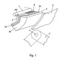
- Figure 1 shows a knee restraint according to a first embodiment of the present invention applied to a passenger car.
- the knee restraint is attached to a cross car beam 1 extending transversely across the width of the vehicle approximately between the A-pillars such that the knee restraint extends across the car in front of the occupant's knees 7 and beneath the instrument panel.
- the knee restraint is attached to the cross car beam 1 by means of two cantilevered support brackets 2 (only one side shown) provided adjacent each side of a transverse member 3.
- the support brackets 2 are located in the region of the left and the right knee impact line.
- the transverse member 3 defines a knee impact element formed from a first or inner layer of relatively rigid high density foam 3a (e.g. at least 100g/l foam density) providing a reinforcement means extending between the support brackets 2 to resist bending/displacement of the central region of the transverse member 3 and a second or outer layer of relatively low density foam 3b (e.g. 30-60 g/l foam density) intended to absorb the impact of the occupant's knees 7 therewith in the event of a frontal collision.
- relatively low density foam 3b it is possible to implement a deformable thin wall structure from plastic or metal (for example honeycomb structures).
- the outer layer of foam 3a would be covered by a skin or cover 5 of plastic or vinyl material, which might form part of the instrument panel or interior of the vehicle, or the knee restraint might be mounted behind the instrument panel or vehicle interior trim.
- the transverse member 3 extends across the steering column assembly 6, beneath the instrument panel. In the event of a frontal impact the knees 7 of the vehicle occupant impact the transverse member 3, the energy of such impact being at least partially absorbed by deformation of the outer layer of low density foam 3b.
- the first or inner layer of relatively rigid high density foam 3a resists deflection or bowing of the transverse member 3 in the unsupported region between the support brackets 2 which might otherwise lead or guide the occupant's knees towards the steering column assembly 6 which might lead to an increased risk of injury to the occupant.
- each of the cantilevered support brackets 2 is provided with a notch 2M adjacent the cross car beam 1 which creates a preferential bending point about which the brackets 2 can bend during impact of the occupant's knees 7 with the transverse member 3 to further absorb the energy of impact.
- the stiffness of the each bracket 2 can be varied or "tuned" to compensate for different forces applied to each side of the transverse member 3 by the occupant's right and left knee, to ensure that each side of the transverse member 3 deflects by an equal amount, thus avoiding potentially dangerous twisting of the occupant's torso which might otherwise occur if each side of the transverse member 3 was deformed by different amounts.
- the wall thickness, of the transverse member 3, the outer layer of low density foam 3b, the inner layer of relatively rigid high density foam 3a, as well as of the inlay 4 can be selected in each of the left and right knee impact areas to provide accordingly different system resistance and rigidity properties in each impact area.
- the reinforcement means reinforcing the transverse member 3 comprises a rigid sheet like inlay 4 of high density foam, plastic or metal (such as steel, aluminium or magnesium).
- the impact absorbing foam layer 3b is preferably integrally moulded with the inlay 4.
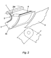
- the remainder of the knee restraint is identical in construction to that of the first embodiment and thus will not be described in more detail.
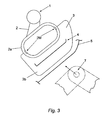
- the support brackets 2 are attached to the transverse member 3 by means of hollow deformable members 2a in the form of a closed loop having notches 2M on opposite inner sides thereof aligned normally to the expected direction of impact such that the resistance of the deformable members 2a to a crushing deformation can be selected to provide the desired degree of deformation such that the deformations of the support brackets 2 in response to impact of the right and left knees of the vehicle occupant in a frontal impact are equal to avoid rotation of the occupant's torso.
- the reinforcement means comprises a sheet of rigid material 4 embedded within the impact absorbing foam material 3b of the transverse member 3, said sheet 4 extending through the transverse member 3 between the support brackets 2 to resist deflection of the transverse member 3 in the region between the support brackets 2 which might cause the occupant's knees 7 to be guided towards the steering column assembly 6.
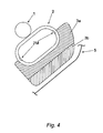
- the fourth embodiment shown in Figure 4 is similar to the third embodiment shown in Figure 3 , having a similar type of support bracket 2.
- the support brackets 2 may be attached to the cross car beam 1, for example by welding or fasteners, or may be formed integrally therewith.
- the main difference between the fourth embodiment and the third is that the reinforcement means preventing bending of the transverse member 3 is provided by a layer of higher density foam 3a sandwiched with the layer of low density energy absorbing foam 3b.
- the low density energy absorbing foam 3b needs to be reinforced (with either an inlay 4 or with a rigid foam component 3a) in order to prevent deflection of the transverse member in the region of the steering column assembly that would otherwise guide the occupant's knees towards the rigid structures of the steering column assembly because of the reduced wall thickness of the transverse member in the region of the steering column assembly.
- the proposed system optimally protects the vehicle front seat occupants, particularly the driver, during a frontal collision. Because tuning of the properties of the stiffness of the left and right knee impact areas is possible, the occupant's knees can be guided & supported in a controlled way, in correlation with the restraint system, in order to obtain a smooth driver motion during a collision, without dangerous body rotation.
Abstract
Description
- The present invention relates to a knee restraint for a vehicle and in particular a knee restraint to support, guide and protect the knees of the front seat occupant's of a vehicle, more particularly a car, during a frontal collision.
- The use of airbags and seat belts have greatly reduced head and upper body injuries of vehicle occupants during frontal collisions. However, the occupant's legs and pelvic region frequently sustain serious injury due to impact of the occupant's knees with rigid cabin structures and components, for example the steering column assembly and instrument panel supports.
- Areas of the occupant's body at particular risk from injury are the Femur and Tibia, as well as the hip joints and pelvis, thus the forces and moments which are applied to such joints by impact of the knees with the cabin structures and components must not be allowed to exceed a certain limits.
- Whilst it is known to provide energy absorbing structures in the region where knee impact is likely to occur, such structures are usually poorly supported in the region of the steering column assembly which can lead to increased deflection of the instrument panel in such region which can cause the driver's knees to be guided towards the steering column assembly, increasing the risk of injury.
- Furthermore, the resistance to deflection and rigidity of the left and right knee impact areas can vary due to different design shapes and structures of such regions of the instrument panel and glove box which are a function of the styling and packaging of the components as well as the components' properties. Such difference in resistance to deflection results in a difference in the deflection of the occupant's left and right knee during a frontal collision which can cause the occupant's head and torso to rotate, adversely affecting the occupant's safety and risk of injury.
-
US 4,721,329 discloses a deformable knee bolster exhibiting positive knee capture by means of pocketing deformation of the knee bolster that occurs upon knee impact with the bolster. Such document does not address the problem of torso rotation. - According to the present invention there is provided a knee restraint for a vehicle as claimed in
claim 1. - The transverse member is connectable to the vehicle body by means of a first support member at or adjacent a first side of the transverse member and a second support member at or adjacent a second side of the transverse member, the relative stiffness of the first and second support members being predetermined or selected to provide substantially equal deflection in the case of an impact by a respective left and right knee of a vehicle occupant, thereby preventing rotation of the occupant's body during impact with the knee restraint in the event of a collision.
- Preferably each of the first and second support members includes at least one notch, or cut-out, or other region of reduced material thickness or cross section in each support member, the stiffness of each of the first and second support members being determined by the size and/or shape of the notch or cut-out therein.
- Preferably the reinforcement means extends between the support members. The reinforcement means may be affixed to the support members.
- Preferably the transverse member includes a first layer of energy absorbing foam for absorbing the impact of the occupant's knees therewith. The reinforcement means may be affixed to or embedded within the first layer of energy absorbing foam.
- In one embodiment, the reinforcement means comprises a second layer of foam having a greater stiffness and/or hardness and/or density than the first layer of foam. Preferably the first layer of foam has a density of between 30 and 60 g/l and the second layer of foam has a density of at least 100g/l.
- In an alternative embodiment the reinforcement means comprises a sheet of rigid material. The sheet of rigid material may be formed from plastic or from a metal, such as steel, aluminium or magnesium. Alternatively the reinforcement means may comprise a thin walled deformable structure to further improve energy absorbtion properties of the knee restraint.
- Preferably the support members are adapted to be deformable to absorb the impact of the occupant's knees with the knee restraint.
- The support members can be formed in different designs using different materials (Al, Steel, Mg, Plastic, etc.) and technologies (rolled formed, deep drawn, die cast, moulded, etc.).
- Embodiments of the invention will now be described, by way of example only, with reference to the drawings, in which:
-
Figure 1 is a part sectional perspective view of part of a knee restraint according to a first embodiment of the invention; -
Figure 2 is a part sectional perspective view of a part of a knee restraint according to a second embodiment of the invention; -
Figure 3 is a part sectional side view of a knee restraint according to a third embodiment of the invention; -
Figure 4 is a part sectional side view of a fourth embodiment of the invention; -
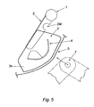
Figure 5 is a part sectional side view of fifth embodiment of the invention. -
Figure 1 shows a knee restraint according to a first embodiment of the present invention applied to a passenger car. The knee restraint is attached to across car beam 1 extending transversely across the width of the vehicle approximately between the A-pillars such that the knee restraint extends across the car in front of the occupant'sknees 7 and beneath the instrument panel. The knee restraint is attached to thecross car beam 1 by means of two cantilevered support brackets 2 (only one side shown) provided adjacent each side of atransverse member 3. Thesupport brackets 2 are located in the region of the left and the right knee impact line. - The
transverse member 3 defines a knee impact element formed from a first or inner layer of relatively rigidhigh density foam 3a (e.g. at least 100g/l foam density) providing a reinforcement means extending between thesupport brackets 2 to resist bending/displacement of the central region of thetransverse member 3 and a second or outer layer of relativelylow density foam 3b (e.g. 30-60 g/l foam density) intended to absorb the impact of the occupant'sknees 7 therewith in the event of a frontal collision. As alternative to thelow density foam 3b it is possible to implement a deformable thin wall structure from plastic or metal (for example honeycomb structures). The outer layer offoam 3a would be covered by a skin orcover 5 of plastic or vinyl material, which might form part of the instrument panel or interior of the vehicle, or the knee restraint might be mounted behind the instrument panel or vehicle interior trim. - The
transverse member 3 extends across thesteering column assembly 6, beneath the instrument panel. In the event of a frontal impact theknees 7 of the vehicle occupant impact thetransverse member 3, the energy of such impact being at least partially absorbed by deformation of the outer layer oflow density foam 3b. The first or inner layer of relatively rigidhigh density foam 3a resists deflection or bowing of thetransverse member 3 in the unsupported region between thesupport brackets 2 which might otherwise lead or guide the occupant's knees towards thesteering column assembly 6 which might lead to an increased risk of injury to the occupant. - In the embodiment shown in
Figure 1 , each of thecantilevered support brackets 2 is provided with anotch 2M adjacent thecross car beam 1 which creates a preferential bending point about which thebrackets 2 can bend during impact of the occupant'sknees 7 with thetransverse member 3 to further absorb the energy of impact. By careful selection of the size and depth of thenotch 2M the stiffness of the eachbracket 2 can be varied or "tuned" to compensate for different forces applied to each side of thetransverse member 3 by the occupant's right and left knee, to ensure that each side of thetransverse member 3 deflects by an equal amount, thus avoiding potentially dangerous twisting of the occupant's torso which might otherwise occur if each side of thetransverse member 3 was deformed by different amounts. - Furthermore, for the same reason, the wall thickness, of the
transverse member 3, the outer layer oflow density foam 3b, the inner layer of relatively rigidhigh density foam 3a, as well as of theinlay 4 can be selected in each of the left and right knee impact areas to provide accordingly different system resistance and rigidity properties in each impact area. - In the second embodiment shown in
Figure 2 , the reinforcement means reinforcing thetransverse member 3 comprises a rigid sheet likeinlay 4 of high density foam, plastic or metal (such as steel, aluminium or magnesium). The impact absorbingfoam layer 3b is preferably integrally moulded with theinlay 4. The remainder of the knee restraint is identical in construction to that of the first embodiment and thus will not be described in more detail. - In the third embodiment shown in
Figure 3 , thesupport brackets 2 are attached to thetransverse member 3 by means of hollowdeformable members 2a in the form of a closedloop having notches 2M on opposite inner sides thereof aligned normally to the expected direction of impact such that the resistance of thedeformable members 2a to a crushing deformation can be selected to provide the desired degree of deformation such that the deformations of thesupport brackets 2 in response to impact of the right and left knees of the vehicle occupant in a frontal impact are equal to avoid rotation of the occupant's torso. - The reinforcement means comprises a sheet of
rigid material 4 embedded within the impact absorbingfoam material 3b of thetransverse member 3, saidsheet 4 extending through thetransverse member 3 between thesupport brackets 2 to resist deflection of thetransverse member 3 in the region between thesupport brackets 2 which might cause the occupant'sknees 7 to be guided towards thesteering column assembly 6. - The fourth embodiment shown in
Figure 4 is similar to the third embodiment shown inFigure 3 , having a similar type ofsupport bracket 2. Thesupport brackets 2 may be attached to thecross car beam 1, for example by welding or fasteners, or may be formed integrally therewith. The main difference between the fourth embodiment and the third is that the reinforcement means preventing bending of thetransverse member 3 is provided by a layer ofhigher density foam 3a sandwiched with the layer of low densityenergy absorbing foam 3b. - The fifth embodiment shown in
Figure 5 is similar to the second embodiment although the design of thesupport brackets 2 and reinforcement means 4 is slightly different. Thesupport brackets 2 again comprise cantilevered arms attached to the cross car beam 1 (for example by welding or fasteners such as screws), each support bracket having a notch or cut-out provided adjacent the cross car beam by means of which the stiffness of the bracket (resistance to bending) can be selected by varying the size of the notch. - In each embodiment of the present invention, during a frontal collision, the left and the
right support brackets 2 deform independently to optimally support and decelerate the left and right knees by equal amounts. Thebrackets 2 limit the maximum tibia and femur force level. The knee restraint system according to the present invention provides increased crash energy absorption levels and an optimized occupant behaviour during a frontal collision. By selecting therespective notch size 2M in each support bracket, the resistance to deflection and rigidity for eachbracket 2 can be predetermined in a cost effective way to provide equal deflection of the left and right knee impact areas in a frontal collision to thus avoid rotation of the occupant's torso. - The low density
energy absorbing foam 3b needs to be reinforced (with either aninlay 4 or with arigid foam component 3a) in order to prevent deflection of the transverse member in the region of the steering column assembly that would otherwise guide the occupant's knees towards the rigid structures of the steering column assembly because of the reduced wall thickness of the transverse member in the region of the steering column assembly. - The proposed system optimally protects the vehicle front seat occupants, particularly the driver, during a frontal collision. Because tuning of the properties of the stiffness of the left and right knee impact areas is possible, the occupant's knees can be guided & supported in a controlled way, in correlation with the restraint system, in order to obtain a smooth driver motion during a collision, without dangerous body rotation.
Claims (13)
- A knee restraint for a vehicle comprising a transverse member (3) connectable to the body (1) of the vehicle to be disposed in the region below the instrument panel of the vehicle in front of the knees (7) of an occupant, the transverse member (3) being connectable to the vehicle body (1) by means of support members (2) provided at or adjacent each side of the transverse member (3), whereby the transverse member (3) comprises reinforcement means (4) provided in the region between said support members (2) to resist deflection of the transverse member (3) in said region, characterised in that the transverse member (3) is connectable to the vehicle body (1) by means of a first support member (2) at or adjacent a first side of the transverse member and a second support member at or adjacent a second side of the transverse member, the relative stiffness of the first and second support members (2) being selected or predetermined to provide substantially equal deflection in the case of an impact by a respective left and right knee of a vehicle occupant, thereby preventing rotation of the occupant's body during impact with the knee restraint in the event of a collision.
- A knee restraint as claimed in claim 1, wherein the reinforcement means (4) extends between the support members (2).
- A knee restraint as claimed in claim 2, wherein the reinforcement means (4) is affixed to the support members (2).
- A knee restraint as claimed in any preceding claim, wherein the transverse member (3) includes a first layer of energy absorbing foam (3b) for absorbing the impact of the occupant's knees therewith.
- A knee restraint as claimed in claim 4 wherein the reinforcement means (4) is affixed to or embedded within the first layer of foam (3b).
- A knee restraint as claimed in claim 4 or claim 5, wherein the reinforcement means (4) comprises a second layer of foam (3a) having a greater stiffness and/or hardness and/or density than the first layer of foam (3b).
- A knee restraint as claimed in claim 6, wherein the first layer of foam (3b) has a density of between 30 and 60 g/l and the second layer of foam (3a) has a density of at least 100g/l.
- A knee restraint as claimed in any of claims 1 to 5 wherein the reinforcement means (4) comprises a sheet of rigid material.
- A knee restraint as claimed in claim 8, wherein sheet of rigid material (4) is formed from plastic or a metal.
- A knee restraint as claimed in any of claims 1 to 5, wherein the reinforcement means (4) comprises a thin walled deformable structure.
- A knee restraint as claimed in any preceding claim, wherein the support members (2) are adapted to be deformable to absorb the impact of the occupant's knees (7) with the knee restraint.
- A knee restraint as claimed in any preceding claim, wherein each of the first and second support members (2) includes at least one notch, cut-out or other region of reduced material thickness or cross section (2M), the stiffness of each of the first and second support members (2) being determined by the size and/or shape of the notch or cut-out (2M) therein
- A knee restraint as claimed in any preceding claim, wherein the wall thickness of the transverse member (3) in the left and right knee impact areas is selected or adapted to provide preselected energy absorbtion properties and/or rigidity.
Priority Applications (3)
| Application Number | Priority Date | Filing Date | Title |
|---|---|---|---|
| EP04257356A EP1661769B1 (en) | 2004-11-26 | 2004-11-26 | Knee restraint for a vehicle |
| AT04257356T ATE426527T1 (en) | 2004-11-26 | 2004-11-26 | KNEE SUPPORT FOR MOTOR VEHICLES |
| DE602004020236T DE602004020236D1 (en) | 2004-11-26 | 2004-11-26 | Knee support for motor vehicles |
Applications Claiming Priority (1)
| Application Number | Priority Date | Filing Date | Title |
|---|---|---|---|
| EP04257356A EP1661769B1 (en) | 2004-11-26 | 2004-11-26 | Knee restraint for a vehicle |
Publications (2)
| Publication Number | Publication Date |
|---|---|
| EP1661769A1 EP1661769A1 (en) | 2006-05-31 |
| EP1661769B1 true EP1661769B1 (en) | 2009-03-25 |
Family
ID=34930848
Family Applications (1)
| Application Number | Title | Priority Date | Filing Date |
|---|---|---|---|
| EP04257356A Not-in-force EP1661769B1 (en) | 2004-11-26 | 2004-11-26 | Knee restraint for a vehicle |
Country Status (3)
| Country | Link |
|---|---|
| EP (1) | EP1661769B1 (en) |
| AT (1) | ATE426527T1 (en) |
| DE (1) | DE602004020236D1 (en) |
Families Citing this family (1)
| Publication number | Priority date | Publication date | Assignee | Title |
|---|---|---|---|---|
| JP6065525B2 (en) * | 2012-11-06 | 2017-01-25 | 三菱自動車工業株式会社 | Vehicle knee collision protection structure |
Family Cites Families (7)
| Publication number | Priority date | Publication date | Assignee | Title |
|---|---|---|---|---|
| US3929948A (en) * | 1971-11-03 | 1975-12-30 | Gen Tire & Rubber Co | Method for fabricating impact absorbing safety structure |
| JPS63523Y2 (en) * | 1979-04-10 | 1988-01-07 | ||
| US4721329A (en) * | 1986-04-11 | 1988-01-26 | Breed Corporation | Elastically restoring knee bolster for motor vehicles |
| US5098124A (en) * | 1990-09-06 | 1992-03-24 | Automotive Technologies International Inc. | Padding to reduce injuries in automobile accidents |
| US5273314A (en) * | 1991-10-17 | 1993-12-28 | Toyota Jidosha Kabushiki Kaisha | Supporting bracket for knee panel |
| US6145880A (en) * | 1997-12-19 | 2000-11-14 | General Motors Corporation | Knee bolster assembly |
| US6869123B2 (en) * | 2001-11-26 | 2005-03-22 | General Electric Company | Instrument panel thermoplastic energy absorbers |
-
2004
- 2004-11-26 AT AT04257356T patent/ATE426527T1/en not_active IP Right Cessation
- 2004-11-26 EP EP04257356A patent/EP1661769B1/en not_active Not-in-force
- 2004-11-26 DE DE602004020236T patent/DE602004020236D1/en active Active
Also Published As
| Publication number | Publication date |
|---|---|
| DE602004020236D1 (en) | 2009-05-07 |
| ATE426527T1 (en) | 2009-04-15 |
| EP1661769A1 (en) | 2006-05-31 |
Similar Documents
| Publication | Publication Date | Title |
|---|---|---|
| KR0154887B1 (en) | Door trim energy absorbing structure | |
| KR0151666B1 (en) | Knee bolster for passsenger side of automotive vehicle | |
| US8029041B2 (en) | Door trim-integrated pelvic impact energy-absorbing construction for vehicle | |
| EP1951556B1 (en) | Variable energy-absorbing system for the occupants of a vehicle. | |
| EP1663725B1 (en) | Structural knee bolster | |
| US6145880A (en) | Knee bolster assembly | |
| US7185917B2 (en) | Knee bolster structure | |
| US7338075B2 (en) | Knee bolster | |
| US6793246B2 (en) | Knee support for occupants | |
| US6883833B2 (en) | Knee protector | |
| US6837518B2 (en) | Reinforcement structure for instrument panel | |
| JP4845510B2 (en) | Vehicle knee protector | |
| CN100478222C (en) | Arrangement for protecting a motor vehicle passenger's knees and instrument panel therefor | |
| JPH11129840A (en) | Impact absorbing member | |
| EP1661769B1 (en) | Knee restraint for a vehicle | |
| EP1572493B1 (en) | Vehicle seat with a pelvis energy management device | |
| CN116890780A (en) | Seat with side air bag for vehicle | |
| JP4538303B2 (en) | Knee guard | |
| JP4136876B2 (en) | Active knee bolster | |
| US7334816B2 (en) | Knee protection device for occupants of a motor vehicle | |
| JP2784019B2 (en) | Knee protector structure for vehicle | |
| US7318605B2 (en) | Knee support element for motor vehicle | |
| JP3195127B2 (en) | Car occupant protection equipment | |
| JPH0680056A (en) | Occupant crash protection device for automobile | |
| RU2334633C2 (en) | Dash panel absorbing driver's inertial load |
Legal Events
| Date | Code | Title | Description |
|---|---|---|---|
| PUAI | Public reference made under article 153(3) epc to a published international application that has entered the european phase |
Free format text: ORIGINAL CODE: 0009012 |
|
| AK | Designated contracting states |
Kind code of ref document: A1 Designated state(s): AT BE BG CH CY CZ DE DK EE ES FI FR GB GR HU IE IS IT LI LU MC NL PL PT RO SE SI SK TR |
|
| AX | Request for extension of the european patent |
Extension state: AL HR LT LV MK YU |
|
| 17P | Request for examination filed |
Effective date: 20060606 |
|
| 17Q | First examination report despatched |
Effective date: 20060907 |
|
| AKX | Designation fees paid |
Designated state(s): AT BE BG CH CY CZ DE DK EE ES FI FR GB GR HU IE IS IT LI LU MC NL PL PT RO SE SI SK TR |
|
| GRAP | Despatch of communication of intention to grant a patent |
Free format text: ORIGINAL CODE: EPIDOSNIGR1 |
|
| GRAS | Grant fee paid |
Free format text: ORIGINAL CODE: EPIDOSNIGR3 |
|
| GRAA | (expected) grant |
Free format text: ORIGINAL CODE: 0009210 |
|
| AK | Designated contracting states |
Kind code of ref document: B1 Designated state(s): AT BE BG CH CY CZ DE DK EE ES FI FR GB GR HU IE IS IT LI LU MC NL PL PT RO SE SI SK TR |
|
| REG | Reference to a national code |
Ref country code: GB Ref legal event code: FG4D |
|
| REG | Reference to a national code |
Ref country code: CH Ref legal event code: EP |
|
| REG | Reference to a national code |
Ref country code: IE Ref legal event code: FG4D |
|
| REF | Corresponds to: |
Ref document number: 602004020236 Country of ref document: DE Date of ref document: 20090507 Kind code of ref document: P |
|
| PG25 | Lapsed in a contracting state [announced via postgrant information from national office to epo] |
Ref country code: SI Free format text: LAPSE BECAUSE OF FAILURE TO SUBMIT A TRANSLATION OF THE DESCRIPTION OR TO PAY THE FEE WITHIN THE PRESCRIBED TIME-LIMIT Effective date: 20090325 Ref country code: FI Free format text: LAPSE BECAUSE OF FAILURE TO SUBMIT A TRANSLATION OF THE DESCRIPTION OR TO PAY THE FEE WITHIN THE PRESCRIBED TIME-LIMIT Effective date: 20090325 |
|
| PG25 | Lapsed in a contracting state [announced via postgrant information from national office to epo] |
Ref country code: SE Free format text: LAPSE BECAUSE OF FAILURE TO SUBMIT A TRANSLATION OF THE DESCRIPTION OR TO PAY THE FEE WITHIN THE PRESCRIBED TIME-LIMIT Effective date: 20090625 Ref country code: PL Free format text: LAPSE BECAUSE OF FAILURE TO SUBMIT A TRANSLATION OF THE DESCRIPTION OR TO PAY THE FEE WITHIN THE PRESCRIBED TIME-LIMIT Effective date: 20090325 Ref country code: AT Free format text: LAPSE BECAUSE OF FAILURE TO SUBMIT A TRANSLATION OF THE DESCRIPTION OR TO PAY THE FEE WITHIN THE PRESCRIBED TIME-LIMIT Effective date: 20090325 |
|
| NLV1 | Nl: lapsed or annulled due to failure to fulfill the requirements of art. 29p and 29m of the patents act | ||
| PG25 | Lapsed in a contracting state [announced via postgrant information from national office to epo] |
Ref country code: BE Free format text: LAPSE BECAUSE OF FAILURE TO SUBMIT A TRANSLATION OF THE DESCRIPTION OR TO PAY THE FEE WITHIN THE PRESCRIBED TIME-LIMIT Effective date: 20090325 |
|
| PG25 | Lapsed in a contracting state [announced via postgrant information from national office to epo] |
Ref country code: PT Free format text: LAPSE BECAUSE OF FAILURE TO SUBMIT A TRANSLATION OF THE DESCRIPTION OR TO PAY THE FEE WITHIN THE PRESCRIBED TIME-LIMIT Effective date: 20090901 Ref country code: ES Free format text: LAPSE BECAUSE OF FAILURE TO SUBMIT A TRANSLATION OF THE DESCRIPTION OR TO PAY THE FEE WITHIN THE PRESCRIBED TIME-LIMIT Effective date: 20090706 Ref country code: CZ Free format text: LAPSE BECAUSE OF FAILURE TO SUBMIT A TRANSLATION OF THE DESCRIPTION OR TO PAY THE FEE WITHIN THE PRESCRIBED TIME-LIMIT Effective date: 20090325 Ref country code: EE Free format text: LAPSE BECAUSE OF FAILURE TO SUBMIT A TRANSLATION OF THE DESCRIPTION OR TO PAY THE FEE WITHIN THE PRESCRIBED TIME-LIMIT Effective date: 20090325 |
|
| PG25 | Lapsed in a contracting state [announced via postgrant information from national office to epo] |
Ref country code: NL Free format text: LAPSE BECAUSE OF FAILURE TO SUBMIT A TRANSLATION OF THE DESCRIPTION OR TO PAY THE FEE WITHIN THE PRESCRIBED TIME-LIMIT Effective date: 20090325 Ref country code: SK Free format text: LAPSE BECAUSE OF FAILURE TO SUBMIT A TRANSLATION OF THE DESCRIPTION OR TO PAY THE FEE WITHIN THE PRESCRIBED TIME-LIMIT Effective date: 20090325 Ref country code: IS Free format text: LAPSE BECAUSE OF FAILURE TO SUBMIT A TRANSLATION OF THE DESCRIPTION OR TO PAY THE FEE WITHIN THE PRESCRIBED TIME-LIMIT Effective date: 20090725 Ref country code: RO Free format text: LAPSE BECAUSE OF FAILURE TO SUBMIT A TRANSLATION OF THE DESCRIPTION OR TO PAY THE FEE WITHIN THE PRESCRIBED TIME-LIMIT Effective date: 20090325 |
|
| PG25 | Lapsed in a contracting state [announced via postgrant information from national office to epo] |
Ref country code: BG Free format text: LAPSE BECAUSE OF FAILURE TO SUBMIT A TRANSLATION OF THE DESCRIPTION OR TO PAY THE FEE WITHIN THE PRESCRIBED TIME-LIMIT Effective date: 20090625 Ref country code: DK Free format text: LAPSE BECAUSE OF FAILURE TO SUBMIT A TRANSLATION OF THE DESCRIPTION OR TO PAY THE FEE WITHIN THE PRESCRIBED TIME-LIMIT Effective date: 20090325 |
|
| PLBE | No opposition filed within time limit |
Free format text: ORIGINAL CODE: 0009261 |
|
| STAA | Information on the status of an ep patent application or granted ep patent |
Free format text: STATUS: NO OPPOSITION FILED WITHIN TIME LIMIT |
|
| 26N | No opposition filed |
Effective date: 20091229 |
|
| PG25 | Lapsed in a contracting state [announced via postgrant information from national office to epo] |
Ref country code: MC Free format text: LAPSE BECAUSE OF NON-PAYMENT OF DUE FEES Effective date: 20091130 |
|
| REG | Reference to a national code |
Ref country code: CH Ref legal event code: PL |
|
| GBPC | Gb: european patent ceased through non-payment of renewal fee |
Effective date: 20091126 |
|
| REG | Reference to a national code |
Ref country code: IE Ref legal event code: MM4A |
|
| REG | Reference to a national code |
Ref country code: FR Ref legal event code: ST Effective date: 20100730 |
|
| PG25 | Lapsed in a contracting state [announced via postgrant information from national office to epo] |
Ref country code: GR Free format text: LAPSE BECAUSE OF FAILURE TO SUBMIT A TRANSLATION OF THE DESCRIPTION OR TO PAY THE FEE WITHIN THE PRESCRIBED TIME-LIMIT Effective date: 20090626 Ref country code: LI Free format text: LAPSE BECAUSE OF NON-PAYMENT OF DUE FEES Effective date: 20091130 Ref country code: IE Free format text: LAPSE BECAUSE OF NON-PAYMENT OF DUE FEES Effective date: 20091126 Ref country code: CH Free format text: LAPSE BECAUSE OF NON-PAYMENT OF DUE FEES Effective date: 20091130 Ref country code: FR Free format text: LAPSE BECAUSE OF NON-PAYMENT OF DUE FEES Effective date: 20091130 |
|
| PG25 | Lapsed in a contracting state [announced via postgrant information from national office to epo] |
Ref country code: GB Free format text: LAPSE BECAUSE OF NON-PAYMENT OF DUE FEES Effective date: 20091126 |
|
| PG25 | Lapsed in a contracting state [announced via postgrant information from national office to epo] |
Ref country code: IT Free format text: LAPSE BECAUSE OF FAILURE TO SUBMIT A TRANSLATION OF THE DESCRIPTION OR TO PAY THE FEE WITHIN THE PRESCRIBED TIME-LIMIT Effective date: 20090325 |
|
| PG25 | Lapsed in a contracting state [announced via postgrant information from national office to epo] |
Ref country code: LU Free format text: LAPSE BECAUSE OF NON-PAYMENT OF DUE FEES Effective date: 20091126 |
|
| PG25 | Lapsed in a contracting state [announced via postgrant information from national office to epo] |
Ref country code: HU Free format text: LAPSE BECAUSE OF FAILURE TO SUBMIT A TRANSLATION OF THE DESCRIPTION OR TO PAY THE FEE WITHIN THE PRESCRIBED TIME-LIMIT Effective date: 20090926 |
|
| PG25 | Lapsed in a contracting state [announced via postgrant information from national office to epo] |
Ref country code: TR Free format text: LAPSE BECAUSE OF FAILURE TO SUBMIT A TRANSLATION OF THE DESCRIPTION OR TO PAY THE FEE WITHIN THE PRESCRIBED TIME-LIMIT Effective date: 20090325 |
|
| PG25 | Lapsed in a contracting state [announced via postgrant information from national office to epo] |
Ref country code: CY Free format text: LAPSE BECAUSE OF FAILURE TO SUBMIT A TRANSLATION OF THE DESCRIPTION OR TO PAY THE FEE WITHIN THE PRESCRIBED TIME-LIMIT Effective date: 20090325 |
|
| PGFP | Annual fee paid to national office [announced via postgrant information from national office to epo] |
Ref country code: DE Payment date: 20161123 Year of fee payment: 13 |
|
| REG | Reference to a national code |
Ref country code: DE Ref legal event code: R119 Ref document number: 602004020236 Country of ref document: DE |
|
| PG25 | Lapsed in a contracting state [announced via postgrant information from national office to epo] |
Ref country code: DE Free format text: LAPSE BECAUSE OF NON-PAYMENT OF DUE FEES Effective date: 20180602 |