EP1663725B1 - Structural knee bolster - Google Patents
Structural knee bolster Download PDFInfo
- Publication number
- EP1663725B1 EP1663725B1 EP04761769A EP04761769A EP1663725B1 EP 1663725 B1 EP1663725 B1 EP 1663725B1 EP 04761769 A EP04761769 A EP 04761769A EP 04761769 A EP04761769 A EP 04761769A EP 1663725 B1 EP1663725 B1 EP 1663725B1
- Authority
- EP
- European Patent Office
- Prior art keywords
- bolster
- aft
- component
- wall
- transfer surfaces
- Prior art date
- Legal status (The legal status is an assumption and is not a legal conclusion. Google has not performed a legal analysis and makes no representation as to the accuracy of the status listed.)
- Expired - Fee Related
Links
Images


Classifications
-
- B—PERFORMING OPERATIONS; TRANSPORTING
- B60—VEHICLES IN GENERAL
- B60R—VEHICLES, VEHICLE FITTINGS, OR VEHICLE PARTS, NOT OTHERWISE PROVIDED FOR
- B60R21/00—Arrangements or fittings on vehicles for protecting or preventing injuries to occupants or pedestrians in case of accidents or other traffic risks
- B60R21/02—Occupant safety arrangements or fittings, e.g. crash pads
- B60R21/04—Padded linings for the vehicle interior ; Energy absorbing structures associated with padded or non-padded linings
- B60R21/045—Padded linings for the vehicle interior ; Energy absorbing structures associated with padded or non-padded linings associated with the instrument panel or dashboard
-
- B—PERFORMING OPERATIONS; TRANSPORTING
- B60—VEHICLES IN GENERAL
- B60R—VEHICLES, VEHICLE FITTINGS, OR VEHICLE PARTS, NOT OTHERWISE PROVIDED FOR
- B60R21/00—Arrangements or fittings on vehicles for protecting or preventing injuries to occupants or pedestrians in case of accidents or other traffic risks
- B60R2021/003—Arrangements or fittings on vehicles for protecting or preventing injuries to occupants or pedestrians in case of accidents or other traffic risks characterised by occupant or pedestian
- B60R2021/0039—Body parts of the occupant or pedestrian affected by the accident
- B60R2021/0051—Knees
Definitions
- a relatively strong structure typically a metallic plate, which is attached to the instrument panel structure and which surrounds the steering column envelope.
- the metal plate may be attached to the bolster or to underlying instrument panel structure.
- the metal plate is more properly called a steering column protector and is sometimes referred to colloquially as a knee splitter.
- the function of the structure is to keep the driver's knees spread apart so that neither the knees, the bolster nor any other surrounding structure infringes on the steering column envelope. This ensures that the steering column can collapse in accordance with its designed function.
- the bolster has sufficient strength to prevent a substantial deformation of the bolster about a generally vertical plane when the bolster is subjected to a standardized force.
- the bolster 10 has sufficient lateral length and vertical height, that it serves the desired appearance function and closes the appearance envelope within the vehicle.
Description
- This application claims benefit from United States provisional application Serial No.
60/500,446 filed September 5, 2003 - The invention relates to bolsters for an instrument panel for an automotive vehicle and more particularly to a bolster which is located adjacent the steering column of the vehicle.
- In the manufacture of automotive vehicles such as passenger cars and trucks, there are many safety standards that must be met by the vehicle to reduce the likelihood and/or severity of injury to occupants during an accident.
- For example, in the United States, the safety standard FMVSS/208 deals with occupant crash protection during a frontal crash. In order to meet the safety standard, portions of an instrument panel assembly are required to absorb at least some of the energy of an impact by the knees of the driver during a crash. A portion of the instrument panel that is configured to sustain an impact from the knees of a driver during a crash is called a bolster. This is the portion of the instrument panel below the belt line.
- Government tests are conducted on vehicles to determine if they meet the safety standard, based on the statistically median-sized male occupant. The median-size is a statistically determined size whereby 50% of the population is larger and 50% of the population is smaller.
- Vehicle safety standards also require special design parameters relating to the steering column of the vehicle. The steering column must be designed to move in an axial direction if the chest of the driver contacts the steering wheel in the course of a crash. Most steering columns are designed to collapse in an axial direction and the steering column is located and designed with the collapsing structure being calculated on the basis that the steering column is not impacted by other structures within the vehicle. A further aspect of the impact safety design of the vehicle is that the driver's knees will contact the bolster area with one knee on either lateral side of the axis of the steering column. As the driver's knees contact the bolster area, the bolster may bend about a generally vertical plane. Bending of the bolster about a vertical plane may then result in some of the instrument panel structure, including the bolster itself, infringing on the space envelope allowed for the steering column structure. If there is any contact of this surrounding structure with the steering column, then the collapse characteristics of the steering column, in accordance with its design, will be changed due to contact from surrounding structure.
- In order to deal with this problem, it is routine in automotive design to include a relatively strong structure, typically a metallic plate, which is attached to the instrument panel structure and which surrounds the steering column envelope. The metal plate may be attached to the bolster or to underlying instrument panel structure. The metal plate is more properly called a steering column protector and is sometimes referred to colloquially as a knee splitter. The function of the structure is to keep the driver's knees spread apart so that neither the knees, the bolster nor any other surrounding structure infringes on the steering column envelope. This ensures that the steering column can collapse in accordance with its designed function.
- Most vehicles today have structure built in to help absorb the energy generated by the impact of the driver's knees on the bolster. Typically most vehicles have energy absorption brackets mounted laterally to either side of the steering column axis outside the steering column envelope. Energy is dissipated as the driver's knees contact the bolster pushing the bolster against the energy absorption brackets and some energy is dissipated by the energy absorption bracket. The energy absorption brackets are located to provide protection to the median sized person as constrained by the vehicle geometry.
- In the existing design envelope, bolsters applied to the steering wheel area of cars are relatively complicated structures comprising a bolster as well as the steering column protector. The bolster generally is a surface of the instrument panel that would otherwise be available for viewing by a vehicle occupant and thus the bolster area must meet certain appearance characteristics. Heretofore, bolsters have been made from injection-molded parts, which have good appearance characteristics on the surface which is visible within the vehicle. However, due to the very nature of injection molding, parts made by the injection molding process often have less strength that might otherwise be available from the plastic resins used in the injection molding process. In such designs, an injection-molded bolster is created which has suitable appearance characteristics and the bolster is strengthened by a metallic plate. The steering column protector serves the function of protecting the steering column with the assumption that the driver's knees will be located substantially directly aft of the energy absorption brackets.
- While this is a complicated and expensive structure to manufacture, there is also the question of what happens if the driver's knees are not located directly aft of the energy absorption structure. This may be as a result of the driver not meeting the 50 percentile adult male physical-size and the drivers seating position may locate the knees at some point other than directly aft of the energy absorption brackets.
-
US 5,865,468 describes an energy absorbing vehicle knee bolster having an aluminium hollow rectangular box form for assembly to an vehicle instrument panel having a steering column axis and at least two energy absorbing brackets located laterally to either side thereof, said bolster comprises a forward wall and a aft wall, said forward wall with a forward surface includes a first bolster surface and a second bolster surface for transferring forces from the bolster to energy absorbing brackets, the bolster further comprises a plurality of laterally extending rib structures, from wich one lower rib extends from adjacent said first bolster transfer surface to adjacent said second bolster transfer surface under a cutaway portion for a steering column. - A first aspect of this invention provides a bolster, for assembly to an instrument panel assembly of an automobile vehicle, as set forth in claim 1.
- The bolster has sufficient strength to prevent a substantial deformation of the bolster about a generally vertical plane when the bolster is subjected to a standardized force.
- In accordance with a preferred embodiment of the invention, the forward component is blow molded.
- In accordance with a particularly preferred embodiment of the invention the aft component is injection molded.
- In accordance with another aspect of the invention, the bolster includes bolster transfer surfaces for transferring forces applied to the aft surface of the aft component to vehicle structure adjacent the bolster transfer surfaces.
- In accordance with another aspect of the invention, the bolster comprises rib structures for transferring forces applied to the aft surface of the aft component at other than directly aft of the bolster transfer surfaces, to the bolster transfer surfaces.
- Various other features and objects of the invention may be completely understood from reference to the following description of a preferred embodiment of the invention.
- A more complete understanding of the invention may be had by reference to the following drawings, in which:
-
Figure 1 is a perspective view of a first embodiment of the invention; -
Figure 2 is a cross section along the line 2-2 of the embodiment illustrated inFigure 1 ; -
Figure 3 is a perspective view of an alternate embodiment of the invention; -
Figure 4 is a cross section of the embodiment ofFigure 3 along the line 4-4; -
Figure 5 is a cross sectional view of the embodiment shown inFigure 3 along the line 5-5; -
Figure 6 is an exploded view of the embodiment illustrated inFigure 3 , and -
Figure 7 is a perspective view of another alternate embodiment of the invention. -
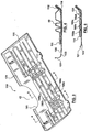
Figure 1 illustrates a one-piece bolster 10. Thebolster 10 has a forward facingsurface 12 and anaft facing surface 14. The directions fore and aft or rearward and forward are used throughout this disclosure to refer to directions within the vehicle. The aft facing surface of the bolster is visible within the drivers compartment of the vehicle with the forward surface facing toward the front bumper, a surface which is not generally visible from within the vehicle. It will be understood that a bolster is typically a curved structure rather than planar, thus throughout this disclosure the surfaces and walls are referred to as generally aft and generally forward. - By reference to
Figure 2 , it will be noted that thebolster 10 is a hollow structure having aforward wall 16 and anaft wall 18. Theaft wall 18 has anaft surface 20 and an internalrear wall surface 22. Theforward wall 16 has aforward surface 24 and an internalforward wall surface 26. - The
bolster 10 includes a firstbolster transfer surface 30 and a secondbolster transfer surface 32. Thebolster transfer surfaces - The bolster is configured to provide a steering column cut out. This is shown in
Figure 1 by the curve marked 40. Thepoint 42 is intended to indicate the location of the axis of the steering column when the bolster 10 is installed to the instrument panel assembly. It will be noted that the bolstercontact surfaces steering column axis 42. This is the usual location of the energy absorption brackets in most standard vehicles. This is arranged on the assumption that the driver's knees at the time of impact will be located laterally to either side of the steering column. - Because the energy absorption brackets have a relatively straight flat surface for contact by the bolster, advantageously the bolster
transfer surface 30 is bounded by a pair of generally vertically extendingrib structures transfer surface 32 is bounded by a similar pair of generally vertically extendingrib structures Figure 1 , it will also be noted that the bolster 10 comprises generally horizontally extending rib structures 60. In the example illustrated, there are foursuch rib structures - The
rib structures Figure 2 . In the blow molding process, a parison is extruded and mold portions are closed over the parison. A blowing gas is delivered to the interior of the parison and the parison is expanded against the walls of the mold cavity of the mold portions. The mold cavity may have projections, which are fixed or the mold portions may have one or several moving components. During the blow molding process, the parison may be manipulated by slides within the molds or other structures so as to bring the generally forward wall into contact with the generally aft wall as shown atFigure 2 . As shown inFigures 1 and 2 , this will create generally longitudinally extending ribs. - As an alternative to what is shown in
Figure 2 where the ribs are longitudinally extending, the ribs could be formed by a series of cones dimples or depressions. Other than providing longitudinally extending ribs, a series of such cones, dimples or depressions can provide the same structural strength as a longitudinally extending rib. The cones or depressions are most advantageously formed in the forward wall so that the forward wall is brought into contact with the aft wall, which remains relatively smoothly curved. This is for appearance purposes as the aft facing wall of the bolster 10 will provide a surface, which may be visible in the vehicle. The term rib structure is used in this disclosure and in the claims to describe all such structures, whether ribs, cones, dimples, depressions, etc. which provide strength and reinforcement to the blow molded structure by bringing the forward and aft walls into contact. - The generally vertically extending
ribs rib structures ribs transfer surfaces - The generally horizontally extending ribs 60 extend laterally across the bolster. The ribs 60 extend from adjacent a first bolster
transfer surface 30 to adjacent the second bolstertransfer surface 32. Advantageously, as shown inFigure 1 , the rib structures 60 can extend laterally into the bolstertransfer surfaces transfer surfaces - Although the standard design standards assume that the 50 percentile adult, male driver will have knees located directly aft of the energy absorption brackets, the bolster 10 acts essentially as a horizontally oriented beam so that the knee impact can occur at other than directly aft of the energy absorption brackets and the bolster
transfer surfaces - Advantageously, as shown in
Figures 1 and 2 , the bolster 10 includes a plurality of horizontally extending rib structures 60. By including a plurality of such horizontally extending rib structures, a bolster 10 can be provided with significant strength so that the bolster will not bend significantly about a generally vertical plane. Because of the strength incorporated into the bolster 10 by the generally horizontally extending rib structures 60, and because the bolster will therefore not bend significantly about a vertical plane, the bolster does not significantly change the shape or location of thecurve 40 which is outside the design envelope of the steering column during a crash event. By incorporating the horizontally extending rib structures 60, the need for a separate steering column protector has been removed. Rather, the horizontal bending strength of the bolster is provided by the rib structures 60 of the blow molded structure. - The bolster 10 may be attached to surrounding instrument panel structure by typical trim molding clips 70 or by use of mounting
flanges 72. Various other mounting systems may be used to locate the bolster in position. - The embodiment of the invention illustrated in the
Figures 1 and 2 is a one-piece bolster which obviates the need for a separate steering column protector. Thesurface 20 of theaft wall 14 will be visible in the vehicle. Depending upon the nature of the vehicle, it may be sufficient for thesurface 20 to be painted. Alternatively, thesurface 20 may be coated with some sort of skin to provide theaft-most surface 14 to present a suitable appearance. - An alternate embodiment of the invention is illustrated in
Figures 3, 4, 5 and6 . Similar numbers have been used to denote similar surfaces as there are several similarities between the two embodiments. The principal difference is that the bolster 110 illustrated inFigures 3, 4, 5 and6 includes an additional component, anaft component 121. The bolster 110 includes aforward component 111 which is similar in most respects to the bolster 10. Theaft component 121 has an aft component, aftsurface 123 and an aft component,forward surface 125. - The
aft component 121 presents itsaft facing surface 123 to persons within the drivers compartment of the vehicle. Advantageously, theaft component 121 is an injection-molded component. Injection molding has suitable appearance characteristics and thus thesurface 123, as the part emerges from the injection mold, may be suitable without further attention. However, theaft surface 123 may be painted, coated with skin or given other suitable surface treatment to meet appearance needs of the particular vehicle. Theforward surface 125, on assembly with theforward component 111, lies so that theforward surface 125 of the aft component contacts theaft wall 114 of the forward component. - As shown in
Figure 5 , theaft component 121 advantageously may be affixed to theforward component 111 by using one or more heat stakes 131. A heat stake is essentially a projection which extends outwardly from the injection-moldedcomponent 121 and through a suitable aperture formed in theforward component 111. Heat is then applied to the tip of the heat stake to form a head or thickening to provide suitable retention of theaft component 121 with theforward component 111. As shown inFigures 3 and6 , three such heat stakes are provided in the bolster 110. - In the embodiment shown in
Figures 1 and 2 , the bolster 10 has sufficient lateral length and vertical height, that it serves the desired appearance function and closes the appearance envelope within the vehicle. - In the embodiment illustrated in
Figures 3, 4, 5 and6 , theforward component 111 provides the strength requirements as discussed in connection with bolster 10 but is not required to extend vertically downwardly to adjacent the steering column envelope. Thus in the embodiment illustrated inFigures 3, 4 and 5 , theperimeter 141 which surrounds the steering column envelope is part of theaft component 121 rather than being part of theforward component 111. However, as with the embodiment ofFigures 1 and 2 , the location and shape of theedge 141 will not substantially change during a crash involving contact of the driver's knee with the bolster 110. Sufficient strength is provided by theforward component 111 to prevent any substantial deflection of theaft component 121. - In effect, the blow molded portion of the bolster 110 provides the structural strength in both the horizontal and vertical sense. The horizontally extending rib structure or structures act to transfer forces from the point or points of impact to the bolster transfer surfaces. The vertically extending structures also serve the function of transferring loads which may be vertically below or above the bolster transfer surfaces. The generally vertically extending rib structures thus also help to distribute the impact loads so that the plurality of horizontally extending rib structures all share in transferring the loads to the bolster transfer surfaces. While in the preferred embodiment illustrated herein, the rib structures extend substantially horizontally and substantially vertically, it will be recognized that the exact orientation of the rib structures is simply a matter of choice. Particularly when using depressions, dimples or cone-like holes, the array of strengthening rib structures incorporated into the bolster may be arranged in various directions to provide the necessary horizontal and vertical load transmission paths discussed herein.
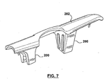
- In the preferred embodiment described herein, the bolster 110 may be used in an existing instrument panel design which incorporates the typical energy absorption brackets. However, as shown in
Figure 7 , utilizing the concepts of the present invention, energy absorption brackets, shown at 200, may be incorporated into a bolster, which is shown at 202. In such a case, the bolster transfer surface will become part of theenergy absorption bracket 200. With this type of system, a subassembly including the bolster 202 with integralenergy absorption brackets 200 may be utilized. This can then be attached to the vehicle structural components such as the instrument panel cross beam (not shown). - As a further alternate embodiment to that which is shown in
Figure 7 , the energy absorbing brackets may be partially integrated into the bolster, instead of being fully integrated. For example, the energy absorbing brackets may be generally C-shaped and the bolster may contain structure sufficient to complement the C-shaped brackets so as to provide similar function to the bolsters and brackets shown and described above. - In discussing these embodiments of the invention, the concept is that forces are applied to the most aft surface of the bolster. In the example of bolster 10, that will be the aft wall of the blow molded component. In the case of the embodiment for the bolster 110, the forces are directed first to the
aft component 121. It is also possible however, particularly with the blow molded bolster 10 and theforward component 111, to incorporate energy absorbing structures within the blow molded component itself. It may be done by including a number of dimples extending between the aft wall and the forward wall of the blow molded component. Those dimples may be designed to help dissipate the energy of impact so that at least a portion of the impact energy is dissipated by collapse of the aft wall of the blow molded component toward the forward wall of the blow molded component. Energy reaching the forward wall can then be transferred to the bolster transfer surfaces for further energy absorption in the energy absorption brackets. - While the above description constitutes the description of the preferred embodiments, it will be appreciated that the present invention is susceptible to modification and change without departing from the fair meaning of the accompanying claims.
Claims (25)
- A bolster (10, 110) for assembly to an instrument panel assembly of an automotive vehicle, said vehicle having a steering column with a steering column axis (42) and at least two energy absorbing brackets located laterally to either side of said steering column axis,
said bolster (10, 110) comprising a unitary structure having a generally forward wall (16) and a generally aft wall (18),
said forward wall (16) having a forward surface (24)
said forward surface (24) including first and second bolster transfer surfaces (30, 32) for transferring forces from said bolster to said energy absorbing brackets,
said bolster further comprising a plurality of generally laterally extending rib structures (60),
said rib structures (60) extending from adjacent said first bolster transfer surface (30) to adjacent said second bolster transfer surface (32),
said plurality of generally laterally extending rib structures (60) being capable of inhibiting bending of said bolster about a vertical plane when struck by a driver's knees, at a point or points which are not directly aft of said bolster transfer surfaces. - The bolster of claim 1 wherein said bolster (10, 110) is blow molded.
- The bolster of claim 2 wherein said rib structure (60) of said bolster incorporates a steering column protector.
- The bolster of claim 3 wherein said rib structures (60) extend laterally of said bolster laterally beyond at least one of said bolster transfer surfaces (30, 32).
- The bolster of claim 3 wherein said bolster includes at least one generally vertically extending rib structure (50) adjacent said first transfer surface (30) to provide lateral support for said bolster relative to said first transfer surface.
- The bolster of claim 5 wherein said bolster includes a plurality of said generally vertically extending rib structures (50, 52) for laterally supporting said bolster to inhibit lateral movement of said bolster relative to said energy absorbing brackets when installed.
- The bolster of claim 1 wherein said bolster includes integral energy absorbing brackets (200).
- The bolster of claim 7 wherein said energy absorbing brackets (200) include said transfer surfaces (30,32).
- The bolster of claim 1 wherein said bolster includes energy absorption dimples located between said forward wall (16) and said aft wall (18) for absorbing energy from forces applied to said aft wall (18).
- The bolster of claim 1 wherein said unitary structure includes, a forward component (111) having said forward wall (24), and an aft component (121), said aft component (121) having an aft surface (123) and a forward surface (125), said forward component (111) having said generally aft wall (114), said aft wall having on aft surface and an aft internal surface,
said forward wall (24) having a forward surface and a forward internal surface. - The bolster of claim 10 wherein said forward component (111) is blow molded.
- The bolster of claim 11 wherein said bolster includes bolster transfer surfaces for transferring forces applied to said aft surface (123) of said aft component (121) to vehicle structure adjacent said transfer surfaces.
- The bolster of claim 12 wherein said bolster comprises rib structures (160) for transferring forces applied to said aft surface (123) of said aft component (121) at other than directly aft of one of said bolster transfer surfaces to said bolster transfer surfaces.
- The bolster of claim 13 wherein said rib structures comprise at least one horizontally acting member for transferring forces laterally between an area of force application to said bolster transfer surfaces.
- The bolster of claim 14 wherein said bolster comprises a plurality of generally laterally extending rib structures.
- The bolster of claim 15 wherein said transfer surfaces of said bolster are located such that at least one first such transfer surface is located laterally to one side of the steering column axis (42) of the vehicles and at least one second transfer surface is located laterally on the other side of the steering column axis of the vehicle.
- The bolster of clam 16 wherein said bolster comprises a plurality of generally horizontally extending rib structures (161) which span the lateral distance between said first and second transfer surfaces.
- The bolster of claim 17 wherein said horizontally extending rib structures comprises an integral steering column protector.
- The bolster of claim 18 wherein said bolster further includes energy absorbing structure so that at least a portion of the energy arising from a force applied to said aft surface is absorbed by said bolster.
- The bolster of claim 17 wherein said plurality of generally horizontally extending ribs (160) are vertically spaced to provide a horizontally supportive beam of acceptable lateral width and acceptable vertical height.
- The bolster of claim 12 wherein said bolster transfer surfaces are adapted to contact at least two separately spaced apart energy absorbing brackets.
- The bolster of claim 21 wherein said bolster transfer surfaces include energy absorbing brackets and said energy absorbing brackets are adapted to be attached to a vehicle instrument panel cross member.
- The bolster of claim 10 wherein said aft component (121) is injection molded.
- The bolster of claim 15 wherein said aft component (121) is fixed to said forward component (111) by a heat stake (131) extending through said aft wall (114) and said forward wall of said forward component (111).
- The bolster of claim 13 wherein said rib structures are defined by areas where said forward wall of the forward component (111) contacts said aft wall (114) of said forward component (111).
Applications Claiming Priority (2)
| Application Number | Priority Date | Filing Date | Title |
|---|---|---|---|
| US50044603P | 2003-09-05 | 2003-09-05 | |
| PCT/CA2004/001605 WO2005023599A1 (en) | 2003-09-05 | 2004-09-01 | Structural knee bolster |
Publications (3)
| Publication Number | Publication Date |
|---|---|
| EP1663725A1 EP1663725A1 (en) | 2006-06-07 |
| EP1663725A4 EP1663725A4 (en) | 2006-12-20 |
| EP1663725B1 true EP1663725B1 (en) | 2009-12-16 |
Family
ID=34272957
Family Applications (1)
| Application Number | Title | Priority Date | Filing Date |
|---|---|---|---|
| EP04761769A Expired - Fee Related EP1663725B1 (en) | 2003-09-05 | 2004-09-01 | Structural knee bolster |
Country Status (7)
| Country | Link |
|---|---|
| US (2) | US7393013B2 (en) |
| EP (1) | EP1663725B1 (en) |
| JP (1) | JP4931056B2 (en) |
| BR (1) | BRPI0414170A (en) |
| CA (1) | CA2535661C (en) |
| DE (1) | DE602004024690D1 (en) |
| WO (1) | WO2005023599A1 (en) |
Cited By (6)
| Publication number | Priority date | Publication date | Assignee | Title |
|---|---|---|---|---|
| US8231138B2 (en) | 2005-06-03 | 2012-07-31 | Salflex Polymers Ltd. | Active bolster |
| US8388020B2 (en) | 2008-04-11 | 2013-03-05 | Salflex Polymers Ltd. | Inflatable multilayer bolster and method of manufacture |
| US8459689B2 (en) | 2009-12-24 | 2013-06-11 | Salflex Polymers Ltd. | Passenger side active knee bolster |
| US8491008B2 (en) | 2010-05-05 | 2013-07-23 | Salflex Polymers Ltd. | Injection molded inflatable active bolster |
| US8579325B2 (en) | 2010-11-09 | 2013-11-12 | Salflex Polymers Ltd. | Active bolster |
| US9254808B2 (en) | 2011-02-07 | 2016-02-09 | Salflex Polymers Limited | Active bolster assembly |
Families Citing this family (24)
| Publication number | Priority date | Publication date | Assignee | Title |
|---|---|---|---|---|
| US7201434B1 (en) | 2005-11-04 | 2007-04-10 | Cadence Innovation Llc | Energy-absorbing bolster for an automotive instrument panel assembly |
| JP5237104B2 (en) * | 2005-11-17 | 2013-07-17 | サルフレックス ポリマーズ リミテッド | Cushion deployment structure |
| US7513566B2 (en) * | 2006-02-06 | 2009-04-07 | Toyota Motor Engineering & Manufacturing North America, Inc. | Headliner stiffener with energy absorbing mechanism |
| KR100857827B1 (en) | 2006-12-07 | 2008-09-10 | 현대자동차주식회사 | Lower panel provided with knee air bag |
| US20090045613A1 (en) * | 2007-02-16 | 2009-02-19 | Collins & Aikman Products Co. | Energy management system |
| US7735865B2 (en) * | 2007-07-19 | 2010-06-15 | Visteon Global Technologies, Inc. | Knee bolster assembly |
| JP4946716B2 (en) * | 2007-08-10 | 2012-06-06 | 日産自動車株式会社 | Undercover support structure |
| US7810869B2 (en) * | 2008-10-07 | 2010-10-12 | Honda Motor Co., Ltd. | Glove box knee bolster assembly for vehicle and method of manufacturing |
| FR2942607B1 (en) * | 2009-02-27 | 2011-04-01 | Faurecia Interieur Ind | ENERGY ABSORPTION DEVICE ARRANGED BETWEEN THE STEERING COLUMN AND THE DRIVER OF A MOTOR VEHICLE |
| WO2010103622A1 (en) * | 2009-03-10 | 2010-09-16 | トヨタ自動車株式会社 | Knee airbag for vehicle |
| JP5956332B2 (en) * | 2009-06-24 | 2016-07-27 | シェイプ・コープShape Corp. | Energy absorber with double-action crush lobe |
| US8267428B2 (en) * | 2009-12-18 | 2012-09-18 | International Automotive Components Group North America, Inc | Energy absorbing countermeasure |
| US8454053B2 (en) * | 2010-02-25 | 2013-06-04 | Ford Global Technologies, Llc | Energy absorbing structure for vehicle knee bolster cover |
| JP5772300B2 (en) * | 2011-06-29 | 2015-09-02 | キョーラク株式会社 | Resin laminate |
| JP5720439B2 (en) * | 2011-06-29 | 2015-05-20 | キョーラク株式会社 | Manufacturing method of resin laminate and molding die of resin laminate |
| US9738052B2 (en) | 2011-06-29 | 2017-08-22 | Kyoraku Co., Ltd | Resin-laminated board |
| US8448980B1 (en) * | 2012-05-01 | 2013-05-28 | Ford Global Technologies, Llc | Active bolster with unsymmetric pleated inflation |
| US8573643B1 (en) | 2012-05-08 | 2013-11-05 | Ford Global Technologies, Llc | Active bolster with gas directing channels |
| CA2873735C (en) * | 2012-05-15 | 2020-03-24 | Salflex Polymers Limited | Passive knee bolster |
| KR101673690B1 (en) * | 2014-11-06 | 2016-11-07 | 현대자동차주식회사 | Knee bolster device for vehicle |
| US9636888B2 (en) | 2015-02-04 | 2017-05-02 | Ford Global Technologies, Llc | Injection molding of hollow articles |
| US9731674B2 (en) * | 2015-09-11 | 2017-08-15 | Ford Global Technologies, Llc | Airbag assembly including depressed region below steering column |
| KR102451872B1 (en) * | 2016-11-21 | 2022-10-06 | 현대자동차 주식회사 | Hybrid bumper beam for vehicles |
| US11242023B2 (en) | 2019-01-11 | 2022-02-08 | Fca Us Llc | Driver knee blocker energy absorption system |
Family Cites Families (23)
| Publication number | Priority date | Publication date | Assignee | Title |
|---|---|---|---|---|
| US3788223A (en) * | 1972-07-13 | 1974-01-29 | Du Pont | Explosive primer |
| JPS61207252A (en) * | 1985-03-12 | 1986-09-13 | Mazda Motor Corp | Knee protector for automobile |
| US4721329A (en) * | 1986-04-11 | 1988-01-26 | Breed Corporation | Elastically restoring knee bolster for motor vehicles |
| JPS632741A (en) * | 1986-06-20 | 1988-01-07 | Tonen Sekiyukagaku Kk | Instrument panel for automobile |
| JP2553224B2 (en) * | 1990-05-22 | 1996-11-13 | 日産自動車株式会社 | Knee protector for automobile |
| US5096223A (en) * | 1990-12-26 | 1992-03-17 | Ford Motor Company | Energy absorbing bracket for interior panels |
| US5326130A (en) * | 1991-11-04 | 1994-07-05 | Chrysler Corporation | Vehicle instrument panel structure |
| JP2599828Y2 (en) * | 1992-10-28 | 1999-09-20 | いすゞ自動車株式会社 | Car knee collision protection device |
| US5370417A (en) * | 1994-04-18 | 1994-12-06 | Davidson Textron Inc. | Automotive knee bolster |
| KR0151666B1 (en) * | 1995-07-28 | 1998-10-15 | 김태구 | Knee bolster for passsenger side of automotive vehicle |
| DE29611869U1 (en) * | 1996-07-08 | 1996-11-07 | Trw Repa Gmbh | Knee restraint for vehicles |
| JP3475694B2 (en) * | 1997-01-31 | 2003-12-08 | いすゞ自動車株式会社 | Knee bolster structure |
| DE29710745U1 (en) * | 1997-06-19 | 1997-10-16 | Trw Repa Gmbh | Knee restraint for vehicles |
| DE19734751B4 (en) * | 1997-08-12 | 2005-05-04 | Daimlerchrysler Ag | Knee protection in a motor vehicle |
| JPH1191454A (en) * | 1997-09-26 | 1999-04-06 | Idemitsu Petrochem Co Ltd | Interior trim member for automobile |
| US6032978A (en) * | 1998-08-07 | 2000-03-07 | Abc Group Interior Systems | Inflatable knee bolster |
| US6213497B1 (en) * | 1998-08-07 | 2001-04-10 | Delphi Technologies, Inc. | Inflatable knee bolster |
| US6758493B2 (en) * | 1998-08-07 | 2004-07-06 | Delphi Technologies, Inc. | Passenger side active knee bolster |
| ES2200751T3 (en) * | 1999-04-22 | 2004-03-16 | TRW OCCUPANT RESTRAINT SYSTEMS GMBH & CO. KG | KNEE PROTECTIVE DEVICE. |
| US6578867B2 (en) * | 2001-06-08 | 2003-06-17 | Delphi Technologies, Inc. | Inflatable system for protection of lower extremities |
| US6991252B2 (en) * | 2002-07-24 | 2006-01-31 | Autoliv Asp, Inc. | Airbag to load plate attachment mechanism |
| DE10240646A1 (en) * | 2002-09-03 | 2004-03-18 | Euromotive Ges.M.B.H. | Device for protecting the legs of a vehicle occupant |
| US6783156B2 (en) * | 2002-10-10 | 2004-08-31 | Lear Corporation | Passenger restraint |
-
2004
- 2004-08-31 US US10/930,535 patent/US7393013B2/en active Active
- 2004-09-01 WO PCT/CA2004/001605 patent/WO2005023599A1/en active Application Filing
- 2004-09-01 JP JP2006525586A patent/JP4931056B2/en active Active
- 2004-09-01 CA CA2535661A patent/CA2535661C/en not_active Expired - Fee Related
- 2004-09-01 EP EP04761769A patent/EP1663725B1/en not_active Expired - Fee Related
- 2004-09-01 BR BRPI0414170-9A patent/BRPI0414170A/en not_active Application Discontinuation
- 2004-09-01 DE DE602004024690T patent/DE602004024690D1/en active Active
-
2008
- 2008-03-06 US US12/043,731 patent/US7481457B2/en active Active
Cited By (13)
| Publication number | Priority date | Publication date | Assignee | Title |
|---|---|---|---|---|
| US9085275B2 (en) | 2005-06-03 | 2015-07-21 | Salflex Polymers Ltd. | Active bolster |
| US8544880B2 (en) | 2005-06-03 | 2013-10-01 | Salflex Polymers Ltd. | Active bolster |
| US8231138B2 (en) | 2005-06-03 | 2012-07-31 | Salflex Polymers Ltd. | Active bolster |
| US8801032B2 (en) | 2005-06-03 | 2014-08-12 | Salflex Polymers Ltd. | Active bolster |
| US10315608B2 (en) | 2005-06-03 | 2019-06-11 | Abc Technologies Inc. | Active bolster |
| US8827307B2 (en) | 2005-11-17 | 2014-09-09 | Salflex Polymers Ltd. | Inflatable bolster |
| US8388020B2 (en) | 2008-04-11 | 2013-03-05 | Salflex Polymers Ltd. | Inflatable multilayer bolster and method of manufacture |
| US8544876B2 (en) | 2008-04-11 | 2013-10-01 | Salflex Polymers Ltd. | Inflatable bolster |
| US8459689B2 (en) | 2009-12-24 | 2013-06-11 | Salflex Polymers Ltd. | Passenger side active knee bolster |
| US8491008B2 (en) | 2010-05-05 | 2013-07-23 | Salflex Polymers Ltd. | Injection molded inflatable active bolster |
| US8579325B2 (en) | 2010-11-09 | 2013-11-12 | Salflex Polymers Ltd. | Active bolster |
| US8931803B2 (en) | 2010-11-09 | 2015-01-13 | Salflex Polymers Ltd. | Active bolster |
| US9254808B2 (en) | 2011-02-07 | 2016-02-09 | Salflex Polymers Limited | Active bolster assembly |
Also Published As
| Publication number | Publication date |
|---|---|
| WO2005023599A1 (en) | 2005-03-17 |
| EP1663725A4 (en) | 2006-12-20 |
| BRPI0414170A (en) | 2006-10-31 |
| US20050052010A1 (en) | 2005-03-10 |
| JP2007504050A (en) | 2007-03-01 |
| DE602004024690D1 (en) | 2010-01-28 |
| CA2535661C (en) | 2010-10-26 |
| WO2005023599B1 (en) | 2005-05-26 |
| JP4931056B2 (en) | 2012-05-16 |
| US7393013B2 (en) | 2008-07-01 |
| EP1663725A1 (en) | 2006-06-07 |
| US20080150268A1 (en) | 2008-06-26 |
| CA2535661A1 (en) | 2005-03-17 |
| US7481457B2 (en) | 2009-01-27 |
Similar Documents
| Publication | Publication Date | Title |
|---|---|---|
| EP1663725B1 (en) | Structural knee bolster | |
| US7201434B1 (en) | Energy-absorbing bolster for an automotive instrument panel assembly | |
| US7185917B2 (en) | Knee bolster structure | |
| US7484792B2 (en) | Glove box assembly exhibiting knee impact force transferring structure with respect to an associated vehicle dash/instrument panel and reinforcing bar | |
| CA2535731C (en) | Instrument panel subassembly including a glove box door | |
| US6609727B2 (en) | Energy absorbing knee bolster assembly | |
| JP2007176447A (en) | Vehicular knee protector | |
| CN100478222C (en) | Arrangement for protecting a motor vehicle passenger's knees and instrument panel therefor | |
| JPH1178965A (en) | Impact absorbing structure provided on car pillar panel | |
| CN106741188B (en) | Collision protection system for front end of vehicle body | |
| JP4538303B2 (en) | Knee guard | |
| JP2962508B2 (en) | Cockpit in the interior room of a car | |
| US7334816B2 (en) | Knee protection device for occupants of a motor vehicle | |
| US20050156421A1 (en) | Knee impact guard for motor vehicles | |
| CN112208473B (en) | Supporting beam mechanism and automobile | |
| KR200147806Y1 (en) | Car body structure of automobile | |
| EP1661769B1 (en) | Knee restraint for a vehicle | |
| KR100302742B1 (en) | Structure for reinforcing dash panel of vehicle | |
| JP4411170B2 (en) | Knee guard structure | |
| KR20040040898A (en) | kneeballster for Automobiles | |
| KR19980012862U (en) | Car dash panel reinforcement structure | |
| KR19980048831U (en) | Car dash panel | |
| KR19980039541U (en) | Floor panel of car |
Legal Events
| Date | Code | Title | Description |
|---|---|---|---|
| PUAI | Public reference made under article 153(3) epc to a published international application that has entered the european phase |
Free format text: ORIGINAL CODE: 0009012 |
|
| 17P | Request for examination filed |
Effective date: 20060324 |
|
| AK | Designated contracting states |
Kind code of ref document: A1 Designated state(s): DE ES FR GB IT |
|
| DAX | Request for extension of the european patent (deleted) | ||
| RBV | Designated contracting states (corrected) |
Designated state(s): DE ES FR GB IT |
|
| A4 | Supplementary search report drawn up and despatched |
Effective date: 20061121 |
|
| RIC1 | Information provided on ipc code assigned before grant |
Ipc: B60R 21/04 20060101AFI20061115BHEP |
|
| 17Q | First examination report despatched |
Effective date: 20070323 |
|
| R17C | First examination report despatched (corrected) |
Effective date: 20071005 |
|
| GRAP | Despatch of communication of intention to grant a patent |
Free format text: ORIGINAL CODE: EPIDOSNIGR1 |
|
| RTI1 | Title (correction) |
Free format text: STRUCTURAL KNEE BOLSTER |
|
| GRAS | Grant fee paid |
Free format text: ORIGINAL CODE: EPIDOSNIGR3 |
|
| GRAA | (expected) grant |
Free format text: ORIGINAL CODE: 0009210 |
|
| AK | Designated contracting states |
Kind code of ref document: B1 Designated state(s): DE ES FR GB IT |
|
| REG | Reference to a national code |
Ref country code: GB Ref legal event code: FG4D |
|
| REF | Corresponds to: |
Ref document number: 602004024690 Country of ref document: DE Date of ref document: 20100128 Kind code of ref document: P |
|
| PG25 | Lapsed in a contracting state [announced via postgrant information from national office to epo] |
Ref country code: ES Free format text: LAPSE BECAUSE OF FAILURE TO SUBMIT A TRANSLATION OF THE DESCRIPTION OR TO PAY THE FEE WITHIN THE PRESCRIBED TIME-LIMIT Effective date: 20100327 |
|
| PLBE | No opposition filed within time limit |
Free format text: ORIGINAL CODE: 0009261 |
|
| STAA | Information on the status of an ep patent application or granted ep patent |
Free format text: STATUS: NO OPPOSITION FILED WITHIN TIME LIMIT |
|
| 26N | No opposition filed |
Effective date: 20100917 |
|
| PG25 | Lapsed in a contracting state [announced via postgrant information from national office to epo] |
Ref country code: IT Free format text: LAPSE BECAUSE OF FAILURE TO SUBMIT A TRANSLATION OF THE DESCRIPTION OR TO PAY THE FEE WITHIN THE PRESCRIBED TIME-LIMIT Effective date: 20091216 |
|
| GBPC | Gb: european patent ceased through non-payment of renewal fee |
Effective date: 20100901 |
|
| REG | Reference to a national code |
Ref country code: FR Ref legal event code: ST Effective date: 20110531 |
|
| PG25 | Lapsed in a contracting state [announced via postgrant information from national office to epo] |
Ref country code: FR Free format text: LAPSE BECAUSE OF NON-PAYMENT OF DUE FEES Effective date: 20100930 |
|
| PG25 | Lapsed in a contracting state [announced via postgrant information from national office to epo] |
Ref country code: GB Free format text: LAPSE BECAUSE OF NON-PAYMENT OF DUE FEES Effective date: 20100901 |
|
| PGFP | Annual fee paid to national office [announced via postgrant information from national office to epo] |
Ref country code: DE Payment date: 20120921 Year of fee payment: 9 |
|
| REG | Reference to a national code |
Ref country code: DE Ref legal event code: R119 Ref document number: 602004024690 Country of ref document: DE Effective date: 20140401 |
|
| PG25 | Lapsed in a contracting state [announced via postgrant information from national office to epo] |
Ref country code: DE Free format text: LAPSE BECAUSE OF NON-PAYMENT OF DUE FEES Effective date: 20140401 |