EP1660795B1 - Verbesserte abdichtung - Google Patents
Verbesserte abdichtung Download PDFInfo
- Publication number
- EP1660795B1 EP1660795B1 EP04768187A EP04768187A EP1660795B1 EP 1660795 B1 EP1660795 B1 EP 1660795B1 EP 04768187 A EP04768187 A EP 04768187A EP 04768187 A EP04768187 A EP 04768187A EP 1660795 B1 EP1660795 B1 EP 1660795B1
- Authority
- EP
- European Patent Office
- Prior art keywords
- sealing element
- seal
- sleeves
- interior volume
- deformable
- Prior art date
- Legal status (The legal status is an assumption and is not a legal conclusion. Google has not performed a legal analysis and makes no representation as to the accuracy of the status listed.)
- Expired - Lifetime
Links
Images


Classifications
-
- E—FIXED CONSTRUCTIONS
- E21—EARTH OR ROCK DRILLING; MINING
- E21B—EARTH OR ROCK DRILLING; OBTAINING OIL, GAS, WATER, SOLUBLE OR MELTABLE MATERIALS OR A SLURRY OF MINERALS FROM WELLS
- E21B33/00—Sealing or packing boreholes or wells
- E21B33/10—Sealing or packing boreholes or wells in the borehole
- E21B33/12—Packers; Plugs
- E21B33/1208—Packers; Plugs characterised by the construction of the sealing or packing means
- E21B33/1212—Packers; Plugs characterised by the construction of the sealing or packing means including a metal-to-metal seal element
-
- E—FIXED CONSTRUCTIONS
- E21—EARTH OR ROCK DRILLING; MINING
- E21B—EARTH OR ROCK DRILLING; OBTAINING OIL, GAS, WATER, SOLUBLE OR MELTABLE MATERIALS OR A SLURRY OF MINERALS FROM WELLS
- E21B17/00—Drilling rods or pipes; Flexible drill strings; Kellies; Drill collars; Sucker rods; Cables; Casings; Tubings
- E21B17/02—Couplings; joints
- E21B17/04—Couplings; joints between rod or the like and bit or between rod and rod or the like
- E21B17/07—Telescoping joints for varying drill string lengths; Shock absorbers
-
- E—FIXED CONSTRUCTIONS
- E21—EARTH OR ROCK DRILLING; MINING
- E21B—EARTH OR ROCK DRILLING; OBTAINING OIL, GAS, WATER, SOLUBLE OR MELTABLE MATERIALS OR A SLURRY OF MINERALS FROM WELLS
- E21B33/00—Sealing or packing boreholes or wells
- E21B33/10—Sealing or packing boreholes or wells in the borehole
- E21B33/12—Packers; Plugs
- E21B33/128—Packers; Plugs with a member expanded radially by axial pressure
-
- F—MECHANICAL ENGINEERING; LIGHTING; HEATING; WEAPONS; BLASTING
- F16—ENGINEERING ELEMENTS AND UNITS; GENERAL MEASURES FOR PRODUCING AND MAINTAINING EFFECTIVE FUNCTIONING OF MACHINES OR INSTALLATIONS; THERMAL INSULATION IN GENERAL
- F16J—PISTONS; CYLINDERS; SEALINGS
- F16J15/00—Sealings
- F16J15/02—Sealings between relatively-stationary surfaces
- F16J15/021—Sealings between relatively-stationary surfaces with elastic packing
- F16J15/028—Sealings between relatively-stationary surfaces with elastic packing the packing being mechanically expanded against the sealing surface
-
- F—MECHANICAL ENGINEERING; LIGHTING; HEATING; WEAPONS; BLASTING
- F16—ENGINEERING ELEMENTS AND UNITS; GENERAL MEASURES FOR PRODUCING AND MAINTAINING EFFECTIVE FUNCTIONING OF MACHINES OR INSTALLATIONS; THERMAL INSULATION IN GENERAL
- F16J—PISTONS; CYLINDERS; SEALINGS
- F16J15/00—Sealings
- F16J15/02—Sealings between relatively-stationary surfaces
- F16J15/06—Sealings between relatively-stationary surfaces with solid packing compressed between sealing surfaces
- F16J15/10—Sealings between relatively-stationary surfaces with solid packing compressed between sealing surfaces with non-metallic packing
- F16J15/12—Sealings between relatively-stationary surfaces with solid packing compressed between sealing surfaces with non-metallic packing with metal reinforcement or covering
- F16J15/128—Sealings between relatively-stationary surfaces with solid packing compressed between sealing surfaces with non-metallic packing with metal reinforcement or covering with metal covering
-
- F—MECHANICAL ENGINEERING; LIGHTING; HEATING; WEAPONS; BLASTING
- F16—ENGINEERING ELEMENTS AND UNITS; GENERAL MEASURES FOR PRODUCING AND MAINTAINING EFFECTIVE FUNCTIONING OF MACHINES OR INSTALLATIONS; THERMAL INSULATION IN GENERAL
- F16L—PIPES; JOINTS OR FITTINGS FOR PIPES; SUPPORTS FOR PIPES, CABLES OR PROTECTIVE TUBING; MEANS FOR THERMAL INSULATION IN GENERAL
- F16L23/00—Flanged joints
- F16L23/16—Flanged joints characterised by the sealing means
- F16L23/18—Flanged joints characterised by the sealing means the sealing means being rings
Definitions
- the present invention relates to seals used between metal surfaces and in particular, though not exclusively, to an annular seal for use in flanges, joints and packers located in oil and gas exploration and production equipment.
- Typical annular seals used to prevent the passage of fluid between two surfaces are elastomeric o-rings.
- the material makes them flexible enough to mould into any deformities in the metal surface, while their compressibility aids in providing a large sealing area.
- these seals can go beyond their operational limits when used within well bores during oil and gas exploration and production due to the extremes of pressure, temperature and the harsh substances which are used.
- metal to metal seals have been developed to provide increased seal strength and reduce seal degradation.
- the sealing ring is a solid metal ring, which is compressed against the seal ring grooves to make the metal-to-metal seal. This is typically achieved by tightening the bolts on the flange. As there is no or little flexibility in the seal, side loading can reduce or remove any seal formed between the groove and flange. Furthermore, older flanges, which are subject to corrosion, can leak. As there is no compliance within the solid metal ring, once a leak appears the seal cannot be re-seated without re-tightening the bolts. In sub-sea applications, it is very expensive to monitor each flange and tighten the bolts as part of a maintenance programme.
- EP 1136734 , DE 3633335 and DE 3712814 all disclose flange ring seals using metal and elastomeric parts. These seals generally comprise a metal insert in the elastomeric material. While this design provides a seal with improved rigidity, the seal against the flange is made by the elastomer, which has the inherent disadvantage of seal degradation.
- WO 02/04783 to Moyes discloses a deformable member comprising a generally hollow cylindrical body defining a wall, the wall includes three circumferential lines of weakness in the form of grooves, with two grooves provided in an outer surface of the member wall, and the other groove provided in an inner surface.
- the member is deformed outwardly to provide a seal, by folding about the lines of weakness.
- the member is typically made of a tough malleable material such as carbon steel.
- a disadvantage of this seal is that by introducing lines of weakness to help the seal deform, the whole structure is weakened. As a result thick sections are required to prevent the element from collapsing under pressure differentials.
- US-5,988,276 to Oneal discloses a compact retrievable well packer which also utilises deformable cylindrical members to form the annular seal and also to lock the well packer in situ. As with Moyes, thick sections are required to prevent the sealing element from collapsing under pressure differentials.
- US 5,961,123 to Ingram et al discloses a seal arrangement which is designed to prevent the seal from extruding uphole or downhole when subjected to extremes of differential pressure.
- the seal material is bounded at either end by metal back-up rings, these rings may be attached to the seal or, as disclosed in US 5,961,123 , be attached to one of the retainers.
- This seal has the typical disadvantages of elastomeric based seals which can be degraded easily by heat and chemicals used downhole.
- US 5,775,429 to Arizmendi et al discloses a seal including a deformable sheath having a body and first and second ends for defining an interior volume proximate to a tool surface.
- the tool surface is the tubing.
- a material located within the interior volume is deformable, when the sheath second end is moved toward the sheath first end.
- the sheath is typically a relatively thin walled tubular member formed from materials like stainless steel or titanium.
- the filler material within the interior volume plastically deforms to advantageously allow the seal to be used oval shaped bore holes. Unfortunately this seal does not perform well in practice.
- volumetric changes in the seal distort the seal and reduce the effectiveness of contact with the bore hole wall or tubular. These volumetric changes occur as the sheath ends are brought together before the seal meets the bore hole wall or tubular and is pressurised.
- US 2002/0166672 discloses a further related seal having a deformable portion made of e.g. metal, and a filler that is, preferably, compressible. Furthermore, US 3,147,016 discloses a flange ring seal comprising a hollow deformable annular casing and a liquid filling this casing.
- a sealing element for providing a seal between a first and a second surface as defined by claim 1.
- the element comprising an inner deformable surface, an outer deformable surface, the inner and outer surfaces being joined at opposed first and second ends, providing a body defining an interior volume entirely bounded by the said surfaces and said ends, a deformable filler material within said interior volume, wherein the element deforms in a predetermined manner to seal between the first and second surfaces when said ends are brought toward each other.
- the material acts as a filler within a continuous body. This allows the shape of the volume of the element to change as the ends are brought together but minimises any change in the said interior volume. By minimising any change in the interior volume until pressure is applied across the seal, the seal will deform in a predetermined manner. As discussed hereinbefore, as a disadvantage with respect to the seal of US 5,775,429 , delamination of the filler from the said surfaces will occur unless the volume change is minimised. This feature of the seal helps prevent the seal collapsing when pressure is applied across the seal, between the inner and outer surfaces.
- the inner and outer deformable surfaces are sleeves, the element whereby being annular. Such an arrangement can provide a seal around a mandrel or tubing. Alternatively the arrangement can provide an annular seal for a flange.
- the inner and outer surfaces are deformable metal sleeves.
- the inner and outer surfaces define a first shape containing the interior volume. Following reformation the inner and outer surface define a second shape.
- the second shape is a cantilever structure arranged longitudinally between the ends.
- the first and second shapes are predetermined.
- the first and second shapes may be annular having a polygon in longitudinal cross-section.
- the polygon is symmetrical across the horizontal plane. In a first embodiment the polygon has ten sides. In a preferred embodiment the polygon has fifteen sides.
- the outer surface defines at least two peaks and at least one trough.
- the inner surface defines at leas two peaks and at least one trough.
- the outer surface defines two peaks and one trough and the inner surface defines three peaks and two troughs.
- the deformable filler material has a first volume.
- the first volume equals the interior volume and both remain substantially equal as the ends are brought together.
- the deformable filler material may be an elastomer, plastic or other flexible material.
- the filler material is a plastic. Use of a plastic is possible as the filler material will allow the seal to have a higher temperature rating than an elastomer, but being entirely encased in metal will not extrude as can be seen with elastomers and such plastics which have unsuitable mechanical properties.
- the outer surface includes a plurality of outer ridges.
- the outer ridges bite into the second surface.
- The is advantageous when the second surface is a wall of the well bore, in a well which is open hole, or a tubing wall for a well which is cased.
- the outer ridges are arranged circumferentially around the outer surface.
- a sealant material is applied to at least a portion of the outer surface. More preferably the portion is between the outer ridges.
- the sealant material may be Teflon ® or the like. The sealant material provides a seal in the event that the primary metal seal of the outer surface fails to work.
- At least one metal insert is located on at least a portion of the outer surface. More preferably the portion is between the outer ridges.
- the metal insert is a ductile inert metal. More preferably, the metal insert is gold.
- the metal insert could be the primary seal, instead of the deformable surfaces or the sealant material.
- the ductile insert could deform to accommodate any scratches or other discontinuities, which the outer surface may not.
- the sealing element forms a cantilever structure during deformation.
- the method includes the step of deforming the outer and inner surfaces of the sealing element.
- the method includes the step of abutting ridges of the sealing element onto at least the second surface.
- the step includes the ridges biting into the second surface.
- the method further includes the step of abutting a sealing material of the sealing element to at least the second surface to improve the sealing characteristics.
- the method further includes the step of abutting a metal insert of the sealing element to at least the second surface to improve the sealing characteristics.
- the apparatus comprises a substantially tubular body upon which is located the first surface; a sealing element according to the first aspect and located around the tubular body, comprising an inner deformable surface, an outer deformable surface, the inner and outer surfaces being joined at opposed first and second ends, providing a sealing body defining as interior volume entirely bounded by the said surfaces and said ends, a deformable filler material within said interior volume; at least one actuating element arranged around and longitudinally moveable relative to the body; the actuating element including means for affixing an end of the sealing element; wherein the sealing element deforms in a predetermined manner to seal between the first and second surfaces when said ends are brought toward each other by movement of the actuating element.
- the apparatus comprises a packer or other downhole tool. More preferably the apparatus comprises a retrievable packer. Alternatively the apparatus comprises an expansion joint or other travelling seal.
- the at least one actuating element is a cone.
- the cone having a bore therethrough for passage of the sealing body.
- Preferably also at least one cone is releasably retained to the tubular body. The cone may be retained by shear pins.
- the at least one actuating element is a threaded ring. By tightening the ring against an end, the sealing element is pre-loaded.
- the inner and outer deformable surfaces are sleeves, the element thereby being annular. Such an arrangement provides a seal around a mandrel or tubing.
- the inner and outer surfaces are deformable metal sleeves.
- the inner and outer surfaces define a first shape containing the interior volume. Following deformation the inner and outer surface define a second shape.
- the second shape is a cantilever structure arranged longitudinally between the ends.
- the first and second shapes are predetermined.
- the first and second shapes may be annular having a polygon in longitudinal cross-section.
- the polygon is symmetrical on the across the horizontal plane. In a first embodiment the polygon has ten sides. In a preferred embodiment the polygon has fifteen sides.
- the outer surface defines at least two peaks and at least one trough.
- the inner surface defines at least two peaks and at least-one trough.
- the outer surface defines two peaks and one trough and the inner surface defines three peaks and two troughs.
- the deformable filler material has a first volume.
- the first volume equals the interior volume and both remain substantially equal as the ends are brought together.
- the deformable filler material may be an elastomer or a plastic.
- the filler material is a plastic. Use of a plastic is possible as the filler material will not be affected by heat, being entirely encased in metal.
- the outer surface includes a plurality of outer ridges.
- the outer ridges bite into the second surface in the well bore.
- the second surface may be a wall of the well bore, when the well is open hole, or tubing wall when the well is cased.
- the outer ridges are arranged circumferentially around the outer surface.
- a sealant material is applied to at least a portion of the outer surface. More preferably the portion is between the outer ridges.
- the sealant material may be Teflon ® or the like. The sealant material provides a seal in the event that the primary metal seal of the outer surface fails to work.
- At least one metal insert is located on art least a portion of the outer surface. More preferably the portion is between the outer ridges.
- the metal insert is a ductile inert metal. More preferably, thy metal insert is gold.
- the metal insert could be the primary seal, instead of the deformable surfaces or the sealant material.
- the ductile insert could deform to accommodate any scratches or other discontinuities, which the outer surface may not.
- a fourth aspect of the present invention there is provided a method of anchoring an apparatus to an inner surface of a well bore as defined by claim 22.
- the method comprises the steps:
- the sealing element forms a cantilever structure during deformation.
- the method includes the step of deforming the outer and inner surfaces of the sealing element.
- the method includes the step of abutting ridges of the sealing element onto the second surface.
- the step includes the ridges biting into the second surface.
- the method further includes the step of abutting a sealing material of the sealing element to the second surface to improve the sealing characteristics.
- a flange ring seal as defined by claim 23 for location in a groove of a mating plate of a flange, the seal in accordance with the first aspect and comprising an inner deformable surface, an outer deformable surface, the inner and outer surfaces being joined at opposed first and second ends, providing a sealing body defining an interior volume entirely bounded by the said surfaces and said ends, a deformable filler material within said interior volume; wherein an end is adapted to be arranged to locate in the groove of the flange and wherein the seal deforms in a predetermined manner an opposing mating plate is brought against the mating plate to seal between the plates.
- the inner and outer deformable surfaces are sleeves, thus forming the ring.
- the inner and outer surfaces are deformable metal sleeves.
- the inner and outer surfaces define a first shape containing the interior volume. Following deformation the inner and outer surface define a second shape.
- the second shape is a cantilever structure arranged longitudinally between the ends.
- the first and second shapes are predetermined.
- the first and second shapes may be annular having a polygon in longitudinal cross-section.
- the polygon is symmetrical on the across the horizontal plane. In a first embodiment the polygon has ten sides. In a preferred embodiment the polygon has fifteen sides. The shape of the polygon, but not the number of sides, varies as the sealing element is deformed.
- the outer, surface defines at least two peaks and at least one trough.
- the inner surface defines at least two peaks and at least one trough.
- the outer surface defines two peaks and one trough and the inner surface defines three peaks and two troughs.
- the deformable filler material has a first volume.
- the first volume equals the interior volume and both remain substantially equal as the ends are brought together.
- the deformable filler material may be an elastomer or a plastic.
- the filler material is a plastic. Use of a plastic is possible as the filler material will not be affected by heat, being entirely encased in metal.
- FIG. 1 there is illustrated a downhole tool, generally indicated by reference numeral 10, according to an embodiment of the present invention.
- Downhole tool 10 is a packer, being an apparatus for providing a seal between a first and a second surface within in a well bore.
- Located on the tool 10, is a sealing element 12, according to an embodiment of the present invention.
- Tool 10 operates by filling the space 14 between the tool body 16 and a bore hole wall, such as a casing 18, to provide a seal between the tool 10 and the casing 18.
- Sealing element 12 comprises a generally cylindrical sleeve which surrounds the tool body 16.
- Element 12 is formed as two concentric metal sleeves, an inner sleeve 20 and an outer sleeve 22. The sleeves are joined at upper 24 and lower 26 ends. Between the sleeves 20,22 is located a filler 28. The filler is entirely contained within the sealing element 12 and bounded on all sides by the metal sleeves 20,22. Thus an interior volume 30 defined by the metal sleeves 20,22 contains an equal volume of the filler 28.
- the sleeves 20,22 are made of a deformable metal.
- the metal is typically stainless steel and the thickness of the sleeve 20,22 is selected to ensure that the steel is deformable under pressure.
- the sleeves are pinched together at the ends 24,26.
- the filler 28 is also of a deformable material.
- the filler may be a plastic or elastomer. However, as the filler 28 is entirely encased in metal, it is not affected by heat and thus a plastic, such as Teflon ® , is preferable.
- the inner sleeve 20 provides an inner surface 32 facing an outer surface 34 of the tool body 16.
- Inner surface 20 is geometrically arranged to provide two symmetrical peaks 36a,b running circumferentially around the surface 20. Peaks 36a,b rest on the surface 34 of the tool body 16.
- a trough 38 lies between the two peaks 36a,6. Trough 38 has symmetrical sloping side walls with a flat base flying parallel to the surface 34 of the tool body 16.
- the outer sleeve 22 has a similar geometrical arrangement on its outer surface 40 to that of the inner surface 32. However peaks 42a,b are somewhat closer together providing a narrower trough 44. The bases of each trough 38,44 are approximately equal in length.
- the surfaces 32,40 When viewed together in cross-section, the surfaces 32,40 provide a polygon having ten sides. Each side is substantially linear. The polygon is symmetrical on a plane perpendicular to the well bore.
- the geometrical arrangement of the sealing element 12 is selected so that when the ends 24,26 are brought together the element 12 will deform in a controlled manner.
- the peaks 36,42 and troughs 38,44 will act like fold lines on the sleeves 20,22 and the element 12 will form a cantilever structure, best seen in Figure 2 .
- the filler 28 has remained in contact with the continuous surface formed by the sleeves 20,22 and defining the anterior volume 30. As delamination has not occurred, the filler 28 helps prevent the seal 12 collapsing when pressure is applied across the seal between the surfaces 32,40 when the seal 12 is in contact with the casing 18.
- sealing element 12 is mounted upon tool body 16.
- the ends 24,26 locate into opposed fixings 48a,b.
- the fixings 48a,b hold the sleeves 20,22 together to provide the interior volume 30 where the filler 28 is located.
- an upper cone 50 which is formed as a sleeve having a sloping surface 54.
- Cone 50 fits over the tool body 16 and is held against the body by shear pins 52a,b.
- the cone 50 has an outer sloping section 54 and a lower lip 56. Lip 56 provides an overhang across the seal 12 and the seal 12 rests upon it. The lip 56 covers the fitting 48a, thereby protecting the end 24 of the seal during operation.
- Cone 58 includes a sloping surface 60 and a lip 62 in an identical manner to cone 50. Cone 58 is bolted to the tool body 16 so that it cannot move during operation of the tool 10. Located outside the cones 50,58 are slips 64,66 as are known in the art.
- tool 10 is mounted on a work string (not shown) and run into a well bore.
- the seal 12 is not set, as illustrated in Figure 1 , so that seal 12 lies toward the body 16 and a space 14 exits between the tool 10 and the casing 18 within the well bore.
- the tool 10 can be run without interfering with any other operations performed in the well bore.
- the tool 10 can be set. This is achieved by moving the cone 50 towards the lower sleeve 58. It will be appreciated by those skilled in the art that either or both cones 50,58 could be moved.
- cone 50 its moved towards sleeve 58.
- the compression applies pressure longitudinally onto the seal 12.
- the pressure causes the peaks 36,42 to move away from each other while the troughs 38,44 move toward each other. It is the geometrical arrangement of the peaks and troughs which cause the seal 12 to deform in this controlled manner. Deformation is complete when the troughs meet. This is illustrated in Figure 2 . During the deformation, the polygon has changed in shape, but the interior volume 30 and the volume of the filler 28 have remained substantially equal and constant throughout.
- Sealing element 12 has ridges 68 located upon its outer surface 40.
- the ridges 68 bite into the casing 38 in order to effect the seal.
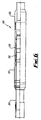
- a sealant material, Teflon ® is located between the ridges 68 to provide an improved seal if the primary metal seal of the ridges 68 fail. This is described with reference to Figure 6 .
- the tool 10 can be retrieved from the well bore, by moving the ends 24,26 apart via movement of one or both of the cones 50,58. Separation of the ends 24,26 pulls the seal longitudinally and the seal 12 returns close to its original shape. A space 14 is thus created between the tool 10 and the casing 18 so that the work string can be pulled from the hole.
- sealing element 112 operates in an identical manner to sealing element 12 in providing a seal between two surfaces.
- ends are shown held in opposed fixings 148a,b as described hereinbefore with reference to figures 1 and 2 .
- Sealing element 112 comprises a continuous cylindrical annulus which may be described as a torus.
- the element 112 is formed from two metal sleeves, a first 120 being arranged inside and coaxial with a second 122.
- the sleeves, 120,122 are joined at upper 124 and lower 126 ends by having adjacent sides of the sleeves meeting over a short distance.
- the ends 124,126 of the sleeves 120,122 are held together by the fixing elements 148a,b.
- a resultant interior volume 130 is created which is entirely bounded by the sleeves 120,122 and the ends 124,126.
- the interior volume 130 is completely filled with a filler 128.
- the filler 128 contacts the sleeves 120,122 and ends 124,126.
- Each sleeve 120, 122 is formed of a metal continuous metal strip.
- the metal is preformed into a shape calculated to deform in a predetermined manner when the ends 124,126 are brought together.
- the inner sleeve 120 in longitudinal cross-section, has a surface 132 which is symmetrically shaped through a horizontal plane equidistant from the ends 124, 126.
- the surface 132 forms a series of peaks and troughs.
- There are two troughs 138a,b which comprise opposing sloping surfaces, bounding a single peak 136 which is a plateau bounded by the sloping surfaces of the troughs 138a,b.
- the outer sleeve 122 has a profile 134 in reverse to the inner sleeve 120 with respect to the element 112.
- peaks 142a,b opposing the troughs 138a,b. These have been levelled to provide a sharp sloping surface into the trough 144 opposite the peak 138.
- Each surface 132,134 is made up of a series of straight sections so that the metal of the sleeve can be bent along fold lines to create the shape required. In longitudinal cross-section through the torus, a polygon is created which defines the interior volume 30 and the volume of filler 128.
- the interior volume 130 remains substantially constant while the shape of the sleeves 120,122 ie. the polygon, deforms in a manner to accentuate the peaks and troughs.
- the filler 128 will deform with the element 112, but will remain in contact with the entire inside surface of the sleeves 120,122 at all times. In this way delamination is prevented which would otherwise cause air pockets in the seal, weakening its ability to withstand both longitudinal pressure applied from the ends 124,126 and transverse pressure applied horizontally between the sleeves 120,122.
- FIG. 4 of the drawings illustrates the seal 112 of Figure 3 when the ends 124,126 have been brought toward each other.
- Like parts to those of Figure 3 have been given the same reference numeral to aid clarity.
- the peaks 142a,b now sit proud of the fixing elements 148a, b.
- the peaks 136,138,142 are plateau like, they provide planar surfaces to improve the sealing properties of the element 112.
- the area of contact of the sealing element 112 is thus predetermined by the dimension of the peaks 136,138,142 in the shape of the original sleeves 120,122.
- the peaks 142a,b on the outer sleeve 122 may include ridge or other material to improve the grip of the sealing element 112 when these positions contact a surface within a well bore. Such additional features are illustrated with reference to Figure 5 .
- Figure 5 shows a part cross-sectional view through the outer sleeve 22 of a sealing element 12. Like parts to those of Figures 1 and 2 have been given the same reference numeral to aid clarity.
- Outer surface 40 of the sleeve 22 has a number of ridges 68a,b located thereon.
- the ridges 68 are protrusions extending from the surface. While they are illustrated as triangular in cross-section, it will be understood that a variety of forms could be used as long as they provide a 'bite' for the seal 12 against the second surface (not shown).
- a sealant material 72 Located between the ridges 68a,b on a portion 70 of the surface is a sealant material 72.
- the material 72 can be a coating or may be a treatment applied to the surface 70.
- the coating could be metal, plastic or another material which will conform to the second surface on contact. While the material 72 is shown as only located between the ridges 68 it will be understood that the ridges could additionally or independently be coated. Teflon ® or the like, would be a suitable material 72.
- a further feature of the surface 40 is in the provision of a groove 74 for an insert 76.
- grooves 74 in the form of indents can be arranged.
- an insert 76 is fitted into each groove 74.
- the insert 76 is a metal, which is preferably a ductile, inert metal, such as gold. In use, the insert 76 would be the primary seal, instead of the outer surface 40 or the sealant material 72. The ductile insert 76 will deform to accommodate any scratches or other discontinuities, which the outer surface 40 may not.
- FIG. 6 illustrates an expansion joint, generally indicated by reference numeral 310, as may be found in a tool string run in a well bore.
- the joint 310 operates by allowing one portion, such as a sleeve 313 to move axially relative to the mandrel 315.
- a seal 312 is located between the moving parts with a pressure differential between the outside and the tubing string.
- the seal 312 is as described hereinbefore with reference to Figures 1-4 .
- the seal 312 is held on a mandrel 315, within a seal bore 317.
- the seal could be held on a housing, with a moveable mandrel.
- the seal 312 is activated by applying a pre-load to deform it slightly.
- a threaded ring 319 is used to apply the pre-load, but other methods could be equally be used.
- the surface of the seal bore 317 is treated in such a manner that friction and wear are minimised. This could be done with tungsten carbide coating or other such methods, which are well understood.
- the seal 312 slides within the seal bore 317, maintaining a dynamic seal during axial movement of the mandrel 315 within the stationary seal bore 317.
- FIGS 7(a) and 7(b) illustrating a sealing element, generally indicated by reference numeral 412, being used as a flange sealing ring.
- a sealing element generally indicated by reference numeral 412
- Each flange 421a,b includes a circular groove 427a,b located on the surface 429a,b of the flange plate 431a,b.
- the seal 412 is sized to locate within the grooves 427a,b. Indeed the grooves 427a,b are profiled to match the outer surface of the ends 424,426 of the seal 412.
- Sealing between the flanges 421a,b is achieved at the first surface, being a combination of the inner edges 433a,b of the grooves 427a,b respectively, and the second surface, being a combination of the outer edges 435a,b of the grooves 427a,b respectively.
- Sealing element 412 is as described with reference to Figures 1-4 , comprising an annular body.
- Element 412 is formed as two concentric metal sleeves, an inner sleeve 420 and an outer sleeve 422.
- the sleeves are joined at upper 424 and lower 426 ends. Joining is by welding of the sleeves 420,422.
- a filler 428 Between the sleeves 420,422 is located a filler 428.
- the filler is entirely contained within the sealing element 412 and bounded on all sides by the metal sleeves 420,422.
- an interior volume 430 defined by the metal sleeves 420,422 contains an equal volume of the filler 428.
- Inner sleeve 420 is geometrically arranged to provide two symmetrical peaks 436a,b running circumferentially around the surface 432.
- a trough 438 lies between the two peaks 436a,6.
- Trough 438 has symmetrical sloping side walls with a flat base 439.
- the outer sleeve 422 has a similar geometrical arrangement on its outer surface 440 to that of the inner surface 432. However peaks 442a,b are somewhat closer together providing a narrower trough 444 without a flat base.
- geometrical arrangement of the sealing element 412 is selected so that when the ends 424,426 are brought together the element 412 will deforms in a controlled manner.
- the peaks 436,442 and troughs 438,444 act like fold lines on the sleeves 420, 422 forming a cantilever structure, which supports the seal.
- the filler 428 supports the seal 412 to prevent the seal from collapsing with pressure applied from the ends 424.
- the interior volume 430 and the volume of the filler 428 remain the same during compression of the seal 412.
- the filler 428 remains in contact with the continuous surface formed by the sleeves 420, 422. Delamination does not occur, thus the filler 428 helps prevent the seal 412 collapsing when pressure is applied across the seal.
- the principal advantage of the present invention is that by entirely enclosing a filler material within two sleeves, volumetric changes in the sealing element are minimised and the seal will deform in a controlled manner.
- a further advantage of an embodiment of the present invention is that it provides a sealing element, which by forming a cantilever structure on deforming, produces a strong seal which can be used to anchor tools in a well bore.
- a yet further advantage of an embodiment of the present invention is that it provides a sealing element which does not collapse under pressure differentials. This is done without the need to thicken the sleeves as it is achieved by the 'rubber pressure' of the filler within the sealing element.
- a still further advantage of an embodiment of the present invention is that it provides a sealing element which does not use elastomers, thus heat and chemicals typically found in well bores will not affect the operation of the seal.
- a still further advantage of an embodiment of the present invention is that it provides a sealing element which has the benefits of flexibility, like an elastomer seal, but is fully metal-to metal.
- a yet further advantage of at least one embodiment of the present invention is that it provides a sealing element which can be used in dynamic applications where it must slide while maintaining a seal.
- the overall size of the sealing element can be varied to suit the tool used.
- the applications describe use in a packer, joint and flange mating but the sealing element could equally be applied to a range of subsea/downhole tools and equipment where a seal and/or anchoring is required.
Landscapes
- Engineering & Computer Science (AREA)
- Mining & Mineral Resources (AREA)
- Life Sciences & Earth Sciences (AREA)
- Geology (AREA)
- General Engineering & Computer Science (AREA)
- Mechanical Engineering (AREA)
- Geochemistry & Mineralogy (AREA)
- General Life Sciences & Earth Sciences (AREA)
- Physics & Mathematics (AREA)
- Fluid Mechanics (AREA)
- Environmental & Geological Engineering (AREA)
- Gasket Seals (AREA)
- Sealing Devices (AREA)
- Diaphragms And Bellows (AREA)
- Glass Compositions (AREA)
- Piezo-Electric Or Mechanical Vibrators, Or Delay Or Filter Circuits (AREA)
- Liquid Crystal (AREA)
Claims (23)
- Ein ringförmiges Dichtungselement (12) zum Bereitstellen einer Dichtung zwischen einer ersten (34) und einer zweiten Oberfläche, wobei das Element dadurch gekennzeichnet ist, dass es Folgendes beinhaltet: eine innere Muffe (20), welche eine innere verformbare Oberfläche bereitstellt, eine äußere Muffe (22), welche eine äußere verformbare Oberfläche bereitstellt, wobei die innere und die äußere Muffe an einem ersten (24) und einem zweiten (26) Ende, die einander gegenüberliegen, verbunden sind, wobei ein Körper bereitgestellt wird, der ein Innenvolumen (30) definiert, das gänzlich von den Oberflächen und den Enden eingegrenzt wird, und ein verformbares Füllmaterial (28) innerhalb des Innenvolumens, wobei die innere und die äußere Muffe (20, 22) verformbare Metallmuffen sind;
wobei die innere und die äußere Muffe (20, 22) je eine Vielzahl von Faltlinien (36, 38, 42, 44) beinhalten;
und wobei sich das Element (12) auf eine zuvor bestimmte Weise verformt, wenn die Enden (24, 26) durch die Verformung der inneren und der äußeren Muffe um ihre jeweiligen Faltlinien einander näher gebracht werden, um dadurch zwischen der ersten (34) und der zweiten Oberfläche eine Dichtung zu bilden. - Dichtungselement gemäß Anspruch 1, wobei die Enden der inneren und der äußeren Muffe (20, 22) aneinander anstoßend lokalisiert sind und durch zugehörige Befestigungselemente zusammengehalten werden.
- Dichtungselement (12) gemäß einem der Ansprüche 1 oder 2, wobei die innere und die äußere Muffe (20, 22) den verformbaren Füllstoff (28) enthalten, wenn die Enden (24, 26) der Muffen einander näher gebracht werden.
- Dichtungselement (12) gemäß einem der vorhergehenden Ansprüche, wobei der Füllstoff (28) angepasst ist, um das Versagen des Dichtungselements (12) zu verhindern, wenn Druck über die Dichtung hinweg angewendet wird.
- Dichtungselement (12) gemäß einem der vorhergehenden Ansprüche, wobei die innere und die äußere Muffe (20, 22) eine erste Form definieren, welche das Innenvolumen (30) enthält, und wobei die innere und die äußere Muffe (20, 22) nach der Verformung eine zweite Form definieren, und wobei ferner die zweite Form eine Auskragungsstruktur ist, die longitudinal zwischen den Enden (24, 26) angeordnet ist.
- Dichtungselement (12) gemäß Anspruch 5, wobei die erste und die zweite Form ringförmig sind und im longitudinalen Querschnitt ein Polygon aufweisen.
- Dichtungselement (12) gemäß Anspruch 6, wobei das Polygon um eine horizontale Ebene, die von den Enden (24, 26) gleichweit entfernt ist, symmetrisch ist.
- Dichtungselement (12) gemäß einem der vorhergehenden Ansprüche, wobei das verformbare Füllmaterial (28) ein erstes Volumen aufweist, das dem Innenvolumen (30) gleicht, und beide Volumina im Wesentlichen gleich bleiben, wenn die Enden (24, 26) zusammengebracht werden.
- Dichtungselement (12) gemäß einem der vorhergehenden Ansprüche, wobei das verformbare Füllmaterial (28) ein Kunststoff ist.
- Dichtungselement (12) gemäß einem der vorhergehenden Ansprüche, wobei die äußere Oberfläche eine Vielzahl von äußeren Erhöhungen (68) umfasst.
- Dichtungselement (12) gemäß einem der vorhergehenden Ansprüche, wobei ein Abdichtungsmaterial auf mindestens einen Abschnitt der äußeren Oberfläche (40) angewendet wird.
- Dichtungselement (12) gemäß einem der vorhergehenden Ansprüche, wobei mindestens ein Metalleinsatz (76) in mindestens einem Abschnitt der äußeren Oberfläche lokalisiert ist.
- Ein Verfahren zum Bereitstellen einer Dichtung zwischen einer ersten (34) und einer zweiten Oberfläche, wobei das Verfahren die folgenden Schritte beinhaltet:(a) Bereitstellen eines Dichtungselements (12) gemäß einem der Ansprüche 1 bis 12, wobei das Dichtungselement (12) ein erstes Innenvolumen (30) und eine erste Form aufweist, und wobei der Füllstoff (28) ein erstes Volumen aufweist, das im Wesentlichen dem ersten Innenvolumen gleicht;(b) Anordnen des Elements (12) neben der ersten Oberfläche (34) und gegenüber der zweiten Oberfläche;(c) Bewegen von einem oder beiden Enden (24, 26) des Dichtungselements (12) zu dem gegenüberliegenden Ende (24, 26) hin;(d) Verformen des Dichtungselements (12) auf eine kontrollierte Weise, um eine zweite Form bereitzustellen, während das erste Innenvolumen (30) und das erste Volumen im Wesentlichen gleich gehalten werden;(e) Berühren des Dichtungselements (12) auf der ersten (34) und der zweiten Oberfläche, um die Dichtung bereitzustellen; und(f) ferner Bewegen von einem oder beiden Enden (24, 26) des Dichtungselements (12) zu dem gegenüberliegenden Ende (24, 26) hin, um einen Druck über das Dichtungselement (12) zwischen der inneren und der äußeren Oberfläche (32, 34) hinweg bereitzustellen.
- Verfahren gemäß Anspruch 13, wobei das Dichtungselement (12) während der Verformung eine Auskragungsstruktur bildet.
- Verfahren gemäß Anspruch 13 oder 14, wobei das Verfahren den Schritt des Verformens der äußeren und der inneren Muffe (22, 20) des Dichtungselements (12) umfasst.
- Verfahren gemäß einem der Ansprüche 13 bis 15, wobei das Verfahren den Schritt des Anstoßens der Erhöhungen (68) des Dichtungselements (12) an mindestens die zweite Oberfläche umfasst.
- Verfahren gemäß einem der Ansprüche 13 bis 16, wobei das Verfahren den Schritt des Anstoßens eines Dichtungsmaterials (72) des Dichtungselements (12) an mindestens die zweite Oberfläche umfasst.
- Verfahren gemäß einem der Ansprüche 13 bis 17, wobei das Verfahren den Schritt des Anstoßens eines Metalleinsatzes (76) des Dichtungselements (12) an mindestens die zweite Oberfläche umfasst.
- Ein Gerät (10) zum Bereitstellen einer Dichtung zwischen einer ersten (34) und einer zweiten Oberfläche innerhalb eines Bohrlochs, wobei das Gerät Folgendes beinhaltet:einen im Wesentlichen röhrenförmigen Körper (16), auf dem die erste Oberfläche (34) lokalisiert ist; gekennzeichnet durch ein Dichtungselement (12) gemäß einem der Ansprüche 1 bis 12, das um den röhrenförmigen Körper (16) herum lokalisiert ist;mindestens ein Betätigungselement (50, 58), das um den röhrenförmigen Körper (16) herum angeordnet und relativ zu diesem longitudinal beweglich ist, wobei das Betätigungselement (50, 58) Mittel (54, 56; 60, 62) zum Berühren eines Endes (24, 26) des Dichtungselements (12) umfasst;wobei sich das Dichtungselement (12) auf die zuvor bestimmte Weise verformt, um zwischen der ersten (34) und der zweiten Oberfläche eine Dichtung zu bilden, wenn die Enden (24, 26) durch die Bewegung des Betätigungselements (50, 58) einander näher gebracht werden.
- Gerät (10) gemäß Anspruch 19, wobei das mindestens eine Betätigungselement (50, 58) ein Konus ist, wobei der Konus zur Durchführung des röhrenförmigen Körpers (16) eine Bohrung dort hindurch aufweist.
- Gerät (10) gemäß Anspruch 19, wobei das mindestens eine Betätigungselement (50, 58) ein Gewindering ist.
- Verfahren gemäß einem der Ansprüche 13 bis 18, wobei das Verfahren ein Verfahren zum Verankern eines Geräts (10) an einer inneren Oberfläche eines Bohrlochs und zum Bereitstellen einer Dichtung zwischen der ersten (34) und der zweiten Oberfläche ist, wobei die innere Oberfläche des Bohrlochs die zweite Oberfläche definiert; und wobei der Schritt des Bereitstellens des Dichtungselements (12) das Bereitstellen eines Geräts (10) gemäß einem der Ansprüche 19 9 bis 21, welches das Dichtungselement (12) gemäß einem der Ansprüche 1 bis 12 umfasst, beinhaltet; und wobei der Schritt des Anordnens des Elements (12) neben der ersten Oberfläche (34) und gegenüber der zweiten Oberfläche das Einlassen des Geräts (10) auf einem Arbeitsstrang in das Bohrloch und somit das Anordnen des Elements (12) beinhaltet; und wobei ferner der Schritt des weiteren Bewegens von einem oder beiden Enden (24, 26) des Dichtungselements (12) zu dem gegenüberliegenden Ende (24, 26) hin auch das Gerät (10) an der zweiten Oberfläche verankert.
- Eine Flanschringdichtung (412) zum Lokalisieren in einer Nut (427a, b) einer Gegenplatte (431a, b) eines Flansches zum Abdichten zwischen einer ersten Oberfläche, die von der Gegenplatte (431a, b) definiert wird, und einer zweiten Oberfläche, die von einer gegenüberliegenden Gegenplatte (431 a, b) definiert wird, dadurch gekennzeichnet, dass die Flanschringdichtung (412) ein Dichtungselement gemäß einem der Ansprüche 1 bis 12 beinhaltet, wobei ein Ende (424, 426) angepasst ist, um angeordnet zu sein, um in der Nut (427a, b) der Gegenplatte (431a, b) des Flansches lokalisiert zu sein, und wobei die Dichtung (412) auf die zuvor bestimmte Weise verformt wird, wenn die gegenüberliegende Gegenplatte (431 a, b) gegen die Gegenplatte (431a, b) gebracht wird, um zwischen den Platten abzudichten.
Applications Claiming Priority (2)
| Application Number | Priority Date | Filing Date | Title |
|---|---|---|---|
| GBGB0320252.0A GB0320252D0 (en) | 2003-08-29 | 2003-08-29 | Improved seal |
| PCT/GB2004/003631 WO2005022012A1 (en) | 2003-08-29 | 2004-08-26 | Improved seal |
Publications (2)
| Publication Number | Publication Date |
|---|---|
| EP1660795A1 EP1660795A1 (de) | 2006-05-31 |
| EP1660795B1 true EP1660795B1 (de) | 2008-12-31 |
Family
ID=28686548
Family Applications (1)
| Application Number | Title | Priority Date | Filing Date |
|---|---|---|---|
| EP04768187A Expired - Lifetime EP1660795B1 (de) | 2003-08-29 | 2004-08-26 | Verbesserte abdichtung |
Country Status (8)
| Country | Link |
|---|---|
| US (3) | US8186685B2 (de) |
| EP (1) | EP1660795B1 (de) |
| AT (1) | ATE419484T1 (de) |
| CA (2) | CA2537153C (de) |
| DE (1) | DE602004018790D1 (de) |
| GB (1) | GB0320252D0 (de) |
| NO (1) | NO334599B1 (de) |
| WO (1) | WO2005022012A1 (de) |
Cited By (1)
| Publication number | Priority date | Publication date | Assignee | Title |
|---|---|---|---|---|
| WO2024076378A1 (en) * | 2022-10-07 | 2024-04-11 | Halliburton Energy Services, Inc. | Sealing element of isolation device with inner core and outer shell |
Families Citing this family (111)
| Publication number | Priority date | Publication date | Assignee | Title |
|---|---|---|---|---|
| US7779903B2 (en) * | 2002-10-31 | 2010-08-24 | Weatherford/Lamb, Inc. | Solid rubber packer for a rotating control device |
| US9682425B2 (en) | 2009-12-08 | 2017-06-20 | Baker Hughes Incorporated | Coated metallic powder and method of making the same |
| GB0320252D0 (en) * | 2003-08-29 | 2003-10-01 | Caledyne Ltd | Improved seal |
| US20070044977A1 (en) * | 2005-08-23 | 2007-03-01 | Schlumberger Technology Corporation | Packer |
| US7510019B2 (en) | 2006-09-11 | 2009-03-31 | Schlumberger Technology Corporation | Forming a metal-to-metal seal in a well |
| US7861775B2 (en) * | 2007-03-05 | 2011-01-04 | Baker Hughes Incorporated | Casing patch |
| US20090072485A1 (en) * | 2007-09-13 | 2009-03-19 | Baker Hughes Incorporated | Expandable metal-to-metal seal |
| NO334336B1 (no) * | 2007-10-29 | 2014-02-10 | Tdw Offshore Services As | Sammenstilling for bruk med en plugg |
| GB0724123D0 (en) * | 2007-12-11 | 2008-01-23 | Rubberatkins Ltd | Improved packing element |
| US8167312B2 (en) * | 2008-07-10 | 2012-05-01 | Vetco Gray Inc. | Metal seal adjustable casing sub |
| GB0812906D0 (en) * | 2008-07-15 | 2008-08-20 | Caledyne Ltd | Well tool |
| US20100072711A1 (en) * | 2008-09-19 | 2010-03-25 | Baker Hughes Incorporated | Expandable metal-to-metal seal |
| US20100090410A1 (en) * | 2008-10-10 | 2010-04-15 | Baker Hughes Incorporated | Expandable metal-to-metal seal |
| ES2688942T3 (es) * | 2009-03-06 | 2018-11-07 | T.D. Williamson Italiana S.R.L. | Máquina de obturación para intervenciones de instalación, reparación, mantenimiento en tuberías de suministro de fluidos a presión |
| EP2233690A1 (de) | 2009-03-13 | 2010-09-29 | BP Alternative Energy International Limited | Flüssigkeitseinspritzung |
| SG173185A1 (en) * | 2009-03-27 | 2011-09-29 | Cameron Int Corp | Full bore compression sealing method |
| GB0910536D0 (en) * | 2009-06-18 | 2009-07-29 | Rolls Royce Plc | A compliant element |
| US10240419B2 (en) | 2009-12-08 | 2019-03-26 | Baker Hughes, A Ge Company, Llc | Downhole flow inhibition tool and method of unplugging a seat |
| GB201004045D0 (en) * | 2010-03-11 | 2010-04-28 | Tendeka Bv | Fully bonded end rings |
| GB2483856A (en) * | 2010-09-21 | 2012-03-28 | Caledyne Ltd | Inflatable packer |
| US9429236B2 (en) | 2010-11-16 | 2016-08-30 | Baker Hughes Incorporated | Sealing devices having a non-elastomeric fibrous sealing material and methods of using same |
| US20120205092A1 (en) * | 2011-02-16 | 2012-08-16 | George Givens | Anchoring and sealing tool |
| CA2827460C (en) | 2011-02-16 | 2017-04-04 | Weatherford/Lamb, Inc. | Downhole tool having expandable annular member |
| WO2012112825A2 (en) | 2011-02-16 | 2012-08-23 | Weatherford/Lamb, Inc. | Anchoring seal |
| US9528352B2 (en) | 2011-02-16 | 2016-12-27 | Weatherford Technology Holdings, Llc | Extrusion-resistant seals for expandable tubular assembly |
| US11215021B2 (en) | 2011-02-16 | 2022-01-04 | Weatherford Technology Holdings, Llc | Anchoring and sealing tool |
| US8631876B2 (en) | 2011-04-28 | 2014-01-21 | Baker Hughes Incorporated | Method of making and using a functionally gradient composite tool |
| US9080098B2 (en) | 2011-04-28 | 2015-07-14 | Baker Hughes Incorporated | Functionally gradient composite article |
| US8955606B2 (en) | 2011-06-03 | 2015-02-17 | Baker Hughes Incorporated | Sealing devices for sealing inner wall surfaces of a wellbore and methods of installing same in a wellbore |
| US8905149B2 (en) | 2011-06-08 | 2014-12-09 | Baker Hughes Incorporated | Expandable seal with conforming ribs |
| US9139928B2 (en) | 2011-06-17 | 2015-09-22 | Baker Hughes Incorporated | Corrodible downhole article and method of removing the article from downhole environment |
| US9707739B2 (en) | 2011-07-22 | 2017-07-18 | Baker Hughes Incorporated | Intermetallic metallic composite, method of manufacture thereof and articles comprising the same |
| US9643250B2 (en) | 2011-07-29 | 2017-05-09 | Baker Hughes Incorporated | Method of controlling the corrosion rate of alloy particles, alloy particle with controlled corrosion rate, and articles comprising the particle |
| US9833838B2 (en) | 2011-07-29 | 2017-12-05 | Baker Hughes, A Ge Company, Llc | Method of controlling the corrosion rate of alloy particles, alloy particle with controlled corrosion rate, and articles comprising the particle |
| US9033055B2 (en) | 2011-08-17 | 2015-05-19 | Baker Hughes Incorporated | Selectively degradable passage restriction and method |
| US9896899B2 (en) * | 2013-08-12 | 2018-02-20 | Downhole Technology, Llc | Downhole tool with rounded mandrel |
| US9109269B2 (en) | 2011-08-30 | 2015-08-18 | Baker Hughes Incorporated | Magnesium alloy powder metal compact |
| US9856547B2 (en) | 2011-08-30 | 2018-01-02 | Bakers Hughes, A Ge Company, Llc | Nanostructured powder metal compact |
| US9090956B2 (en) | 2011-08-30 | 2015-07-28 | Baker Hughes Incorporated | Aluminum alloy powder metal compact |
| US9643144B2 (en) | 2011-09-02 | 2017-05-09 | Baker Hughes Incorporated | Method to generate and disperse nanostructures in a composite material |
| US9309733B2 (en) | 2012-01-25 | 2016-04-12 | Baker Hughes Incorporated | Tubular anchoring system and method |
| US9284803B2 (en) | 2012-01-25 | 2016-03-15 | Baker Hughes Incorporated | One-way flowable anchoring system and method of treating and producing a well |
| US9010416B2 (en) | 2012-01-25 | 2015-04-21 | Baker Hughes Incorporated | Tubular anchoring system and a seat for use in the same |
| US9260926B2 (en) | 2012-05-03 | 2016-02-16 | Weatherford Technology Holdings, Llc | Seal stem |
| US9605508B2 (en) * | 2012-05-08 | 2017-03-28 | Baker Hughes Incorporated | Disintegrable and conformable metallic seal, and method of making the same |
| US8950504B2 (en) | 2012-05-08 | 2015-02-10 | Baker Hughes Incorporated | Disintegrable tubular anchoring system and method of using the same |
| US9016363B2 (en) | 2012-05-08 | 2015-04-28 | Baker Hughes Incorporated | Disintegrable metal cone, process of making, and use of the same |
| US8839874B2 (en) | 2012-05-15 | 2014-09-23 | Baker Hughes Incorporated | Packing element backup system |
| GB2504321B (en) * | 2012-07-26 | 2019-08-28 | Rubberatkins Ltd | Seal element |
| US9540900B2 (en) | 2012-10-20 | 2017-01-10 | Halliburton Energy Services, Inc. | Multi-layered temperature responsive pressure isolation device |
| US9085968B2 (en) | 2012-12-06 | 2015-07-21 | Baker Hughes Incorporated | Expandable tubular and method of making same |
| US9243490B2 (en) | 2012-12-19 | 2016-01-26 | Baker Hughes Incorporated | Electronically set and retrievable isolation devices for wellbores and methods thereof |
| US9145755B2 (en) | 2013-05-02 | 2015-09-29 | Halliburton Energy Services, Inc. | Sealing annular gaps in a well |
| CN203499965U (zh) * | 2013-08-14 | 2014-03-26 | 大庆大华宏业石油工程技术有限公司 | 双层自封超长冲程抽油泵 |
| US9810047B2 (en) * | 2013-08-26 | 2017-11-07 | Baker Hughes | Re-fracturing bottom hole assembly and method |
| US9816339B2 (en) | 2013-09-03 | 2017-11-14 | Baker Hughes, A Ge Company, Llc | Plug reception assembly and method of reducing restriction in a borehole |
| CA2936851A1 (en) | 2014-02-21 | 2015-08-27 | Terves, Inc. | Fluid activated disintegrating metal system |
| US10689740B2 (en) | 2014-04-18 | 2020-06-23 | Terves, LLCq | Galvanically-active in situ formed particles for controlled rate dissolving tools |
| US10865465B2 (en) | 2017-07-27 | 2020-12-15 | Terves, Llc | Degradable metal matrix composite |
| US11167343B2 (en) | 2014-02-21 | 2021-11-09 | Terves, Llc | Galvanically-active in situ formed particles for controlled rate dissolving tools |
| EP2952672A1 (de) * | 2014-06-04 | 2015-12-09 | Welltec A/S | Expandierbares Bohrlochmetallrohr |
| GB201417841D0 (en) * | 2014-10-08 | 2014-11-19 | Meta Downhole Ltd | Morphable Packer |
| US9810037B2 (en) | 2014-10-29 | 2017-11-07 | Weatherford Technology Holdings, Llc | Shear thickening fluid controlled tool |
| NO338447B1 (en) * | 2015-01-19 | 2016-08-15 | Archer Oiltools As | A casing annulus cement foundation system and a method for forming a flange collar constituting a cement foundation |
| US9910026B2 (en) | 2015-01-21 | 2018-03-06 | Baker Hughes, A Ge Company, Llc | High temperature tracers for downhole detection of produced water |
| US10378303B2 (en) | 2015-03-05 | 2019-08-13 | Baker Hughes, A Ge Company, Llc | Downhole tool and method of forming the same |
| US10100956B2 (en) | 2015-03-24 | 2018-10-16 | Quickhub, Llc | Pipe connector systems, devices and methods |
| US10253885B2 (en) | 2015-03-24 | 2019-04-09 | Quickhub, Llc | Pipe connector systems, devices and methods |
| US10557578B2 (en) | 2015-03-24 | 2020-02-11 | Quickhub, Llc | Pipe connector systems, devices and methods |
| US11073233B2 (en) | 2015-03-24 | 2021-07-27 | Quickhub, Llc | Pipe connector systems, devices and methods |
| US11054035B2 (en) | 2015-03-24 | 2021-07-06 | Quickhub, Llc | Pipe connector systems, devices and methods |
| EP3283796B1 (de) * | 2015-04-13 | 2024-12-25 | Oceaneering International, Inc. | Kreisförmige verbundverbinderdichtung und verfahren zur verwendung |
| US10180038B2 (en) | 2015-05-06 | 2019-01-15 | Weatherford Technology Holdings, Llc | Force transferring member for use in a tool |
| US10221637B2 (en) | 2015-08-11 | 2019-03-05 | Baker Hughes, A Ge Company, Llc | Methods of manufacturing dissolvable tools via liquid-solid state molding |
| US10016810B2 (en) | 2015-12-14 | 2018-07-10 | Baker Hughes, A Ge Company, Llc | Methods of manufacturing degradable tools using a galvanic carrier and tools manufactured thereof |
| US10406727B2 (en) | 2016-04-29 | 2019-09-10 | Cnh Industrial America Llc | System and method for processing elastomeric load rings of face seals to provide improved load tolerance |
| GB2554889B (en) * | 2016-10-12 | 2019-01-02 | Poulton Tech Limited | A seal assembly |
| US10634255B2 (en) * | 2016-12-21 | 2020-04-28 | Baker Hughes, A Ge Company, Llc | Pressure activated anti-extrusion ring for annular seal, seal configuration, and method |
| US10472911B2 (en) | 2017-03-20 | 2019-11-12 | Weatherford Technology Holdings, LLC. | Gripping apparatus and associated methods of manufacturing |
| US10519740B2 (en) | 2017-03-20 | 2019-12-31 | Weatherford Technology Holdings, Llc | Sealing apparatus and associated methods of manufacturing |
| US10487616B2 (en) * | 2017-06-28 | 2019-11-26 | Schlumberger Technology Corporation | Packoff seals and processes for using same |
| BR102017018910A2 (pt) | 2017-09-04 | 2019-03-19 | Jose Anisio De Oliveira E Silva | Anel compósito de suporte para soldas de topo e sistema que emprega o dito anel na fabricação de juntas de topo soldadas de seções tubulares metálicas revestidas internamente com materiais sensíveis ao calor |
| CN108533842A (zh) * | 2018-03-27 | 2018-09-14 | 中冶天工集团有限公司 | 一种用于综合管廊穿线管的挤压式密封装置及其安装方法 |
| CN108413152A (zh) * | 2018-05-17 | 2018-08-17 | 苏州宝骅密封科技股份有限公司 | 一种轴向密封组件 |
| US10641056B2 (en) * | 2018-06-20 | 2020-05-05 | Exacta-Frac Energy Services, Inc. | High-expansion packer elements |
| EP3647532A1 (de) | 2018-10-30 | 2020-05-06 | Welltec Oilfield Solutions AG | Ringförmige barriere |
| US11578555B2 (en) * | 2019-08-01 | 2023-02-14 | Vertice Oil Tools Inc. | Methods and systems for a frac plug |
| GB2599829B (en) | 2019-08-06 | 2023-06-14 | Halliburton Energy Services Inc | Expandable metal gas lift mandrel plug |
| WO2021126232A1 (en) | 2019-12-20 | 2021-06-24 | Halliburton Energy Services, Inc. | Barrier coating layer for an expandable member wellbore tool |
| BR112022011008A2 (pt) | 2020-01-17 | 2022-08-16 | Halliburton Energy Services Inc | Método para assentar uma ferramenta de fundo de poço, ferramenta de fundo de poço e sistema de poço |
| MX2022006306A (es) | 2020-01-17 | 2022-06-22 | Halliburton Energy Services Inc | Calentadores para acelerar la colocacion de metal expandible. |
| WO2021173145A1 (en) | 2020-02-28 | 2021-09-02 | Halliburton Energy Services, Inc. | Textured surfaces of expanding metal for centralizer, mixing, and differential sticking |
| MX2023001376A (es) * | 2020-08-05 | 2023-03-03 | Lps Ip Llc | Conexion sellada de tuberia, manga para tuberia y sellos de tuberia bloqueables y metodo de fabricacion de los mismos. |
| WO2022031769A1 (en) * | 2020-08-05 | 2022-02-10 | Lps Ip, Llc | Sealed pipeline connection and raised pipeline sleeve, and method of making same |
| NO20230030A1 (en) | 2020-08-13 | 2023-01-12 | Halliburton Energy Services Inc | Expandable metal displacement plug |
| US11572496B2 (en) | 2020-12-14 | 2023-02-07 | Halliburton Energy Services, Inc. | Expandable metal slurry for wellbore isolation and sealing |
| MX2023009992A (es) | 2021-04-12 | 2023-09-06 | Halliburton Energy Services Inc | Metal expandible como respaldo de elementos elastomericos. |
| US12326060B2 (en) | 2021-05-21 | 2025-06-10 | Halliburton Energy Services, Inc. | Wellbore anchor including one or more activation chambers |
| CN113027377B (zh) * | 2021-05-27 | 2022-03-11 | 东营市正能石油科技有限公司 | 采油用封隔器 |
| ES3013288R1 (es) | 2021-05-28 | 2026-03-05 | Halliburton Energy Services Inc | Trozos individuales separados de metal expandible |
| WO2022250701A1 (en) | 2021-05-28 | 2022-12-01 | Halliburton Energy Services, Inc. | Rapid setting expandable metal |
| NO20231085A1 (en) | 2021-05-29 | 2023-10-13 | Halliburton Energy Services Inc | Using expandable metal as an alternate to existing metal to metal seals |
| WO2022255988A1 (en) | 2021-06-01 | 2022-12-08 | Halliburton Energy Services, Inc. | Expanding metal used in forming support structures |
| US20220389787A1 (en) * | 2021-06-07 | 2022-12-08 | Halliburton Energy Services, Inc. | Collapsible shell packer for metal-to-metal sealing |
| EP4112873A1 (de) * | 2021-07-01 | 2023-01-04 | Welltec Oilfield Solutions AG | Ringförmige barriere |
| WO2023059312A1 (en) | 2021-10-05 | 2023-04-13 | Halliburton Energy Services, Inc. | Expandable metal sealing/anchoring tool |
| US20230204058A1 (en) * | 2021-12-27 | 2023-06-29 | Freudenberg Oil & Gas, Llc | Flange connection |
| CN114517836B (zh) * | 2022-01-14 | 2024-04-12 | 玺智达精密电子(深圳)有限公司 | 一种复合式遇水膨胀橡胶圈 |
| CA3242741A1 (en) * | 2022-01-20 | 2023-07-27 | Tdw Offshore Services As | Pipeline isolation tool with seal having adaptable mechanical support structure |
| US12305459B2 (en) | 2022-06-15 | 2025-05-20 | Halliburton Energy Services, Inc. | Sealing/anchoring tool employing an expandable metal circlet |
| US12385340B2 (en) | 2022-12-05 | 2025-08-12 | Halliburton Energy Services, Inc. | Reduced backlash sealing/anchoring assembly |
Family Cites Families (35)
| Publication number | Priority date | Publication date | Assignee | Title |
|---|---|---|---|---|
| US1136879A (en) * | 1913-06-23 | 1915-04-20 | Daniel Fred Hunt | Well-packing. |
| US2125665A (en) * | 1935-07-01 | 1938-08-02 | M O Johnston | Sleeve packer construction |
| US2119252A (en) * | 1936-04-04 | 1938-05-31 | Guiberson Corp | Well swab |
| FR1095569A (fr) * | 1953-12-11 | 1955-06-03 | Joint Francais | Perfectionnement aux joints métalloplastiques |
| DE1099892B (de) | 1957-06-13 | 1961-02-16 | Joseph Sunnen | Sicherung eines Honsteintraegers bei Honwerkzeugen |
| US3147016A (en) * | 1959-04-06 | 1964-09-01 | Traufler Daniel | Annular gaskets |
| US3163431A (en) * | 1960-06-06 | 1964-12-29 | Charles L Tanner | Seal ring means |
| US3235017A (en) * | 1962-06-28 | 1966-02-15 | Gen Oil Tools Inc | Earth borehole drilling and testing tool |
| US3275335A (en) * | 1963-03-18 | 1966-09-27 | Donaldson Co Inc | High pressure seal |
| US3392785A (en) * | 1966-07-18 | 1968-07-16 | William R. King | Retractable packer |
| US3490777A (en) * | 1967-04-13 | 1970-01-20 | John O Emmerson | Metal seal construction |
| US3776561A (en) * | 1970-10-16 | 1973-12-04 | R Haney | Formation of well packers |
| US4482086A (en) * | 1983-08-04 | 1984-11-13 | Uop Inc. | Expandable packer assembly for sealing a well screen to a casing |
| US4452462A (en) * | 1983-10-06 | 1984-06-05 | Gray Tool Company | Temperature resistant joint packing with E-shaped spring seal |
| US4862967A (en) * | 1986-05-12 | 1989-09-05 | Baker Oil Tools, Inc. | Method of employing a coated elastomeric packing element |
| DE3633335A1 (de) | 1986-10-01 | 1988-04-07 | Ibk Wiesehahn Gmbh & Co Kg | Kammdichtungselement fuer eine dichtung sowie verfahren zu seiner herstellung |
| DE3712814A1 (de) | 1987-04-15 | 1988-11-03 | Ibk Wiesehahn Gmbh & Co Kg | Flanschverbindung fuer den rohrleitungs- und apparatebau |
| GB8726356D0 (en) * | 1987-11-11 | 1987-12-16 | Cameron Iron Works Inc | Wellhead tieback system |
| US5240263A (en) * | 1988-06-01 | 1993-08-31 | Specialist Sealing Limited | Metallic sealing rings and their manufacture |
| US5199497A (en) * | 1992-02-14 | 1993-04-06 | Baker Hughes Incorporated | Shape-memory actuator for use in subterranean wells |
| GB9414113D0 (en) | 1994-07-13 | 1994-08-31 | Specialist Sealing Ltd | Improvements relating to metallic seal rings |
| NO301945B1 (no) * | 1995-09-08 | 1997-12-29 | Broennteknologiutvikling As | Ekspanderende opphentbar broplugg |
| US5961123A (en) | 1996-04-01 | 1999-10-05 | Baker Hughes Incorporated | Metal back-up ring for downhole seals |
| US5775429A (en) * | 1997-02-03 | 1998-07-07 | Pes, Inc. | Downhole packer |
| US6039319A (en) * | 1997-02-24 | 2000-03-21 | Swagelok Company | Hygienic fitting with thermal expansion area for gasket |
| US5988276A (en) | 1997-11-25 | 1999-11-23 | Halliburton Energy Services, Inc. | Compact retrievable well packer |
| US6009951A (en) * | 1997-12-12 | 2000-01-04 | Baker Hughes Incorporated | Method and apparatus for hybrid element casing packer for cased-hole applications |
| US6322087B1 (en) * | 1998-08-28 | 2001-11-27 | Perkinelmer, Inc. | Metallic seal for low load conditions |
| EP1099892A1 (de) * | 1999-11-09 | 2001-05-16 | Witzenmann GmbH Metallschlauch-Fabrik Pforzheim | Abdichtung zwischen zueinander koaxialen axialsymmetrischen Querschnitten von Bauteilen |
| EP1136734A1 (de) | 2000-03-22 | 2001-09-26 | Kroll & Ziller GmbH & Co. KG | Dichtung, insbesondere Flanschdichtung |
| US6446717B1 (en) | 2000-06-01 | 2002-09-10 | Weatherford/Lamb, Inc. | Core-containing sealing assembly |
| GB0016595D0 (en) | 2000-07-07 | 2000-08-23 | Moyes Peter B | Deformable member |
| GB2375575B (en) * | 2000-12-20 | 2003-04-23 | Fmc Technologies | Alternative metallic seals |
| US6854522B2 (en) * | 2002-09-23 | 2005-02-15 | Halliburton Energy Services, Inc. | Annular isolators for expandable tubulars in wellbores |
| GB0320252D0 (en) * | 2003-08-29 | 2003-10-01 | Caledyne Ltd | Improved seal |
-
2003
- 2003-08-29 GB GBGB0320252.0A patent/GB0320252D0/en not_active Ceased
-
2004
- 2004-08-26 CA CA2537153A patent/CA2537153C/en not_active Expired - Lifetime
- 2004-08-26 DE DE602004018790T patent/DE602004018790D1/de not_active Expired - Lifetime
- 2004-08-26 CA CA2797648A patent/CA2797648A1/en not_active Abandoned
- 2004-08-26 AT AT04768187T patent/ATE419484T1/de not_active IP Right Cessation
- 2004-08-26 EP EP04768187A patent/EP1660795B1/de not_active Expired - Lifetime
- 2004-08-26 WO PCT/GB2004/003631 patent/WO2005022012A1/en not_active Ceased
-
2006
- 2006-02-28 US US11/307,921 patent/US8186685B2/en not_active Ceased
- 2006-03-28 NO NO20061418A patent/NO334599B1/no not_active IP Right Cessation
-
2012
- 2012-05-25 US US13/481,201 patent/US8794637B2/en not_active Expired - Lifetime
- 2012-08-28 US US13/597,198 patent/USRE45518E1/en active Active
Cited By (1)
| Publication number | Priority date | Publication date | Assignee | Title |
|---|---|---|---|---|
| WO2024076378A1 (en) * | 2022-10-07 | 2024-04-11 | Halliburton Energy Services, Inc. | Sealing element of isolation device with inner core and outer shell |
Also Published As
| Publication number | Publication date |
|---|---|
| US20060186602A1 (en) | 2006-08-24 |
| US20120312556A1 (en) | 2012-12-13 |
| DE602004018790D1 (de) | 2009-02-12 |
| US8794637B2 (en) | 2014-08-05 |
| GB0320252D0 (en) | 2003-10-01 |
| EP1660795A1 (de) | 2006-05-31 |
| ATE419484T1 (de) | 2009-01-15 |
| NO20061418L (no) | 2006-03-28 |
| USRE45518E1 (en) | 2015-05-19 |
| CA2797648A1 (en) | 2005-03-10 |
| CA2537153C (en) | 2013-02-26 |
| US8186685B2 (en) | 2012-05-29 |
| NO334599B1 (no) | 2014-04-22 |
| CA2537153A1 (en) | 2005-03-10 |
| WO2005022012A1 (en) | 2005-03-10 |
Similar Documents
| Publication | Publication Date | Title |
|---|---|---|
| EP1660795B1 (de) | Verbesserte abdichtung | |
| CA2358312C (en) | Flexible swedge | |
| AU766437B2 (en) | Downhole sealing for production tubing | |
| US6666276B1 (en) | Downhole radial set packer element | |
| US8083001B2 (en) | Expandable gage ring | |
| US10704355B2 (en) | Slotted anti-extrusion ring assembly | |
| US20180023366A1 (en) | Slotted Backup Ring Assembly | |
| US20020014339A1 (en) | Apparatus and method for packing or anchoring an inner tubular within a casing | |
| US20110037230A1 (en) | Expandable packer system | |
| US9617823B2 (en) | Axially compressed and radially pressed seal | |
| EP3119982B1 (de) | Dichtungsanordnung | |
| GB2383361A (en) | A packer/seal produced by plastically deforming a tubular | |
| CA3069867C (en) | Slotted backup ring assembly | |
| NL2039402B1 (en) | Wellbore beam spring travel limiter |
Legal Events
| Date | Code | Title | Description |
|---|---|---|---|
| PUAI | Public reference made under article 153(3) epc to a published international application that has entered the european phase |
Free format text: ORIGINAL CODE: 0009012 |
|
| 17P | Request for examination filed |
Effective date: 20060329 |
|
| AK | Designated contracting states |
Kind code of ref document: A1 Designated state(s): AT BE BG CH CY CZ DE DK EE ES FI FR GB GR HU IE IT LI LU MC NL PL PT RO SE SI SK TR |
|
| 17Q | First examination report despatched |
Effective date: 20060726 |
|
| DAX | Request for extension of the european patent (deleted) | ||
| 17Q | First examination report despatched |
Effective date: 20060726 |
|
| GRAP | Despatch of communication of intention to grant a patent |
Free format text: ORIGINAL CODE: EPIDOSNIGR1 |
|
| GRAS | Grant fee paid |
Free format text: ORIGINAL CODE: EPIDOSNIGR3 |
|
| GRAA | (expected) grant |
Free format text: ORIGINAL CODE: 0009210 |
|
| AK | Designated contracting states |
Kind code of ref document: B1 Designated state(s): AT BE BG CH CY CZ DE DK EE ES FI FR GB GR HU IE IT LI LU MC NL PL PT RO SE SI SK TR |
|
| REG | Reference to a national code |
Ref country code: GB Ref legal event code: FG4D Ref country code: CH Ref legal event code: EP |
|
| REF | Corresponds to: |
Ref document number: 602004018790 Country of ref document: DE Date of ref document: 20090212 Kind code of ref document: P |
|
| REG | Reference to a national code |
Ref country code: IE Ref legal event code: FG4D |
|
| PG25 | Lapsed in a contracting state [announced via postgrant information from national office to epo] |
Ref country code: PL Free format text: LAPSE BECAUSE OF FAILURE TO SUBMIT A TRANSLATION OF THE DESCRIPTION OR TO PAY THE FEE WITHIN THE PRESCRIBED TIME-LIMIT Effective date: 20081231 Ref country code: SI Free format text: LAPSE BECAUSE OF FAILURE TO SUBMIT A TRANSLATION OF THE DESCRIPTION OR TO PAY THE FEE WITHIN THE PRESCRIBED TIME-LIMIT Effective date: 20081231 Ref country code: FI Free format text: LAPSE BECAUSE OF FAILURE TO SUBMIT A TRANSLATION OF THE DESCRIPTION OR TO PAY THE FEE WITHIN THE PRESCRIBED TIME-LIMIT Effective date: 20081231 |
|
| PG25 | Lapsed in a contracting state [announced via postgrant information from national office to epo] |
Ref country code: EE Free format text: LAPSE BECAUSE OF FAILURE TO SUBMIT A TRANSLATION OF THE DESCRIPTION OR TO PAY THE FEE WITHIN THE PRESCRIBED TIME-LIMIT Effective date: 20081231 Ref country code: RO Free format text: LAPSE BECAUSE OF FAILURE TO SUBMIT A TRANSLATION OF THE DESCRIPTION OR TO PAY THE FEE WITHIN THE PRESCRIBED TIME-LIMIT Effective date: 20081231 Ref country code: ES Free format text: LAPSE BECAUSE OF FAILURE TO SUBMIT A TRANSLATION OF THE DESCRIPTION OR TO PAY THE FEE WITHIN THE PRESCRIBED TIME-LIMIT Effective date: 20090411 Ref country code: BE Free format text: LAPSE BECAUSE OF FAILURE TO SUBMIT A TRANSLATION OF THE DESCRIPTION OR TO PAY THE FEE WITHIN THE PRESCRIBED TIME-LIMIT Effective date: 20081231 |
|
| PG25 | Lapsed in a contracting state [announced via postgrant information from national office to epo] |
Ref country code: PT Free format text: LAPSE BECAUSE OF FAILURE TO SUBMIT A TRANSLATION OF THE DESCRIPTION OR TO PAY THE FEE WITHIN THE PRESCRIBED TIME-LIMIT Effective date: 20090601 Ref country code: AT Free format text: LAPSE BECAUSE OF FAILURE TO SUBMIT A TRANSLATION OF THE DESCRIPTION OR TO PAY THE FEE WITHIN THE PRESCRIBED TIME-LIMIT Effective date: 20081231 Ref country code: SE Free format text: LAPSE BECAUSE OF FAILURE TO SUBMIT A TRANSLATION OF THE DESCRIPTION OR TO PAY THE FEE WITHIN THE PRESCRIBED TIME-LIMIT Effective date: 20090331 Ref country code: CZ Free format text: LAPSE BECAUSE OF FAILURE TO SUBMIT A TRANSLATION OF THE DESCRIPTION OR TO PAY THE FEE WITHIN THE PRESCRIBED TIME-LIMIT Effective date: 20081231 |
|
| PG25 | Lapsed in a contracting state [announced via postgrant information from national office to epo] |
Ref country code: SK Free format text: LAPSE BECAUSE OF FAILURE TO SUBMIT A TRANSLATION OF THE DESCRIPTION OR TO PAY THE FEE WITHIN THE PRESCRIBED TIME-LIMIT Effective date: 20081231 |
|
| PG25 | Lapsed in a contracting state [announced via postgrant information from national office to epo] |
Ref country code: DK Free format text: LAPSE BECAUSE OF FAILURE TO SUBMIT A TRANSLATION OF THE DESCRIPTION OR TO PAY THE FEE WITHIN THE PRESCRIBED TIME-LIMIT Effective date: 20081231 |
|
| PLBE | No opposition filed within time limit |
Free format text: ORIGINAL CODE: 0009261 |
|
| STAA | Information on the status of an ep patent application or granted ep patent |
Free format text: STATUS: NO OPPOSITION FILED WITHIN TIME LIMIT |
|
| 26N | No opposition filed |
Effective date: 20091001 |
|
| PG25 | Lapsed in a contracting state [announced via postgrant information from national office to epo] |
Ref country code: BG Free format text: LAPSE BECAUSE OF FAILURE TO SUBMIT A TRANSLATION OF THE DESCRIPTION OR TO PAY THE FEE WITHIN THE PRESCRIBED TIME-LIMIT Effective date: 20090331 |
|
| PG25 | Lapsed in a contracting state [announced via postgrant information from national office to epo] |
Ref country code: MC Free format text: LAPSE BECAUSE OF NON-PAYMENT OF DUE FEES Effective date: 20090831 |
|
| REG | Reference to a national code |
Ref country code: CH Ref legal event code: PL |
|
| PG25 | Lapsed in a contracting state [announced via postgrant information from national office to epo] |
Ref country code: LI Free format text: LAPSE BECAUSE OF NON-PAYMENT OF DUE FEES Effective date: 20090831 Ref country code: CH Free format text: LAPSE BECAUSE OF NON-PAYMENT OF DUE FEES Effective date: 20090831 |
|
| REG | Reference to a national code |
Ref country code: IE Ref legal event code: MM4A |
|
| PG25 | Lapsed in a contracting state [announced via postgrant information from national office to epo] |
Ref country code: IE Free format text: LAPSE BECAUSE OF NON-PAYMENT OF DUE FEES Effective date: 20090826 |
|
| PG25 | Lapsed in a contracting state [announced via postgrant information from national office to epo] |
Ref country code: GR Free format text: LAPSE BECAUSE OF FAILURE TO SUBMIT A TRANSLATION OF THE DESCRIPTION OR TO PAY THE FEE WITHIN THE PRESCRIBED TIME-LIMIT Effective date: 20090401 |
|
| PG25 | Lapsed in a contracting state [announced via postgrant information from national office to epo] |
Ref country code: IT Free format text: LAPSE BECAUSE OF FAILURE TO SUBMIT A TRANSLATION OF THE DESCRIPTION OR TO PAY THE FEE WITHIN THE PRESCRIBED TIME-LIMIT Effective date: 20081231 |
|
| PG25 | Lapsed in a contracting state [announced via postgrant information from national office to epo] |
Ref country code: LU Free format text: LAPSE BECAUSE OF NON-PAYMENT OF DUE FEES Effective date: 20090826 |
|
| PG25 | Lapsed in a contracting state [announced via postgrant information from national office to epo] |
Ref country code: HU Free format text: LAPSE BECAUSE OF FAILURE TO SUBMIT A TRANSLATION OF THE DESCRIPTION OR TO PAY THE FEE WITHIN THE PRESCRIBED TIME-LIMIT Effective date: 20090701 |
|
| PG25 | Lapsed in a contracting state [announced via postgrant information from national office to epo] |
Ref country code: TR Free format text: LAPSE BECAUSE OF FAILURE TO SUBMIT A TRANSLATION OF THE DESCRIPTION OR TO PAY THE FEE WITHIN THE PRESCRIBED TIME-LIMIT Effective date: 20081231 |
|
| PG25 | Lapsed in a contracting state [announced via postgrant information from national office to epo] |
Ref country code: CY Free format text: LAPSE BECAUSE OF FAILURE TO SUBMIT A TRANSLATION OF THE DESCRIPTION OR TO PAY THE FEE WITHIN THE PRESCRIBED TIME-LIMIT Effective date: 20081231 |
|
| REG | Reference to a national code |
Ref country code: DE Ref legal event code: R082 Ref document number: 602004018790 Country of ref document: DE |
|
| REG | Reference to a national code |
Ref country code: GB Ref legal event code: 732E Free format text: REGISTERED BETWEEN 20131003 AND 20131009 |
|
| REG | Reference to a national code |
Ref country code: DE Ref legal event code: R081 Ref document number: 602004018790 Country of ref document: DE Owner name: FREUDENBERG OIL GAS, LCC, HOUSTON, US Free format text: FORMER OWNER: CALEDYNE, LTD., BRIDGE OF DON, ABERDEEN, GB Effective date: 20131025 Ref country code: DE Ref legal event code: R081 Ref document number: 602004018790 Country of ref document: DE Owner name: FREUDENBERG OIL AND GAS UK LIMITED, GB Free format text: FORMER OWNER: CALEDYNE, LTD., BRIDGE OF DON, GB Effective date: 20131025 Ref country code: DE Ref legal event code: R081 Ref document number: 602004018790 Country of ref document: DE Owner name: FREUDENBERG OIL AND GAS UK LIMITED, GB Free format text: FORMER OWNER: CALEDYNE, LTD., BRIDGE OF DON, ABERDEEN, GB Effective date: 20131025 Ref country code: DE Ref legal event code: R081 Ref document number: 602004018790 Country of ref document: DE Owner name: FREUDENBERG OIL & GAS, LCC, HOUSTON, US Free format text: FORMER OWNER: CALEDYNE, LTD., BRIDGE OF DON, ABERDEEN, GB Effective date: 20131025 |
|
| REG | Reference to a national code |
Ref country code: NL Ref legal event code: SD Effective date: 20140917 |
|
| REG | Reference to a national code |
Ref country code: FR Ref legal event code: TP Owner name: FREUDENBERG OIL AND GAS UK LIMITED, GB Effective date: 20140820 Ref country code: FR Ref legal event code: CA Effective date: 20140820 |
|
| REG | Reference to a national code |
Ref country code: DE Ref legal event code: R081 Ref document number: 602004018790 Country of ref document: DE Owner name: FREUDENBERG OIL GAS, LCC, HOUSTON, US Free format text: FORMER OWNER: FREUDENBERG OIL AND GAS UK LIMITED, ABERDEEN, GB Effective date: 20150210 Ref country code: DE Ref legal event code: R081 Ref document number: 602004018790 Country of ref document: DE Owner name: FREUDENBERG OIL & GAS, LCC, HOUSTON, US Free format text: FORMER OWNER: FREUDENBERG OIL AND GAS UK LIMITED, ABERDEEN, GB Effective date: 20150210 |
|
| REG | Reference to a national code |
Ref country code: GB Ref legal event code: 732E Free format text: REGISTERED BETWEEN 20150226 AND 20150304 |
|
| REG | Reference to a national code |
Ref country code: FR Ref legal event code: PLFP Year of fee payment: 12 |
|
| REG | Reference to a national code |
Ref country code: FR Ref legal event code: TP Owner name: FREUDENBERG OIL & GAS LLC, US Effective date: 20151109 |
|
| REG | Reference to a national code |
Ref country code: NL Ref legal event code: PD Owner name: FREUDENBERG OIL AND GAS, LLC; US Free format text: DETAILS ASSIGNMENT: VERANDERING VAN EIGENAAR(S), OVERDRACHT; FORMER OWNER NAME: FREUDENBERG OIL AND GAS UK LIMITED Effective date: 20151106 |
|
| REG | Reference to a national code |
Ref country code: FR Ref legal event code: PLFP Year of fee payment: 13 |
|
| PGFP | Annual fee paid to national office [announced via postgrant information from national office to epo] |
Ref country code: NL Payment date: 20160822 Year of fee payment: 13 |
|
| PGFP | Annual fee paid to national office [announced via postgrant information from national office to epo] |
Ref country code: FR Payment date: 20170810 Year of fee payment: 14 |
|
| REG | Reference to a national code |
Ref country code: NL Ref legal event code: MM Effective date: 20170901 |
|
| REG | Reference to a national code |
Ref country code: FR Ref legal event code: ST Effective date: 20180430 |
|
| PG25 | Lapsed in a contracting state [announced via postgrant information from national office to epo] |
Ref country code: NL Free format text: LAPSE BECAUSE OF NON-PAYMENT OF DUE FEES Effective date: 20170901 |
|
| PG25 | Lapsed in a contracting state [announced via postgrant information from national office to epo] |
Ref country code: FR Free format text: LAPSE BECAUSE OF NON-PAYMENT OF DUE FEES Effective date: 20170831 |
|
| GBPC | Gb: european patent ceased through non-payment of renewal fee |
Effective date: 20180826 |
|
| PG25 | Lapsed in a contracting state [announced via postgrant information from national office to epo] |
Ref country code: GB Free format text: LAPSE BECAUSE OF NON-PAYMENT OF DUE FEES Effective date: 20180826 |
|
| PGFP | Annual fee paid to national office [announced via postgrant information from national office to epo] |
Ref country code: DE Payment date: 20230831 Year of fee payment: 20 |
|
| REG | Reference to a national code |
Ref country code: DE Ref legal event code: R071 Ref document number: 602004018790 Country of ref document: DE |