EP1660795B1 - Improved seal - Google Patents
Improved seal Download PDFInfo
- Publication number
- EP1660795B1 EP1660795B1 EP04768187A EP04768187A EP1660795B1 EP 1660795 B1 EP1660795 B1 EP 1660795B1 EP 04768187 A EP04768187 A EP 04768187A EP 04768187 A EP04768187 A EP 04768187A EP 1660795 B1 EP1660795 B1 EP 1660795B1
- Authority
- EP
- European Patent Office
- Prior art keywords
- sealing element
- seal
- sleeves
- interior volume
- deformable
- Prior art date
- Legal status (The legal status is an assumption and is not a legal conclusion. Google has not performed a legal analysis and makes no representation as to the accuracy of the status listed.)
- Active
Links
- 238000007789 sealing Methods 0.000 claims abstract description 117
- 229910052751 metal Inorganic materials 0.000 claims abstract description 63
- 239000002184 metal Substances 0.000 claims abstract description 63
- 239000000945 filler Substances 0.000 claims abstract description 59
- 239000000463 material Substances 0.000 claims abstract description 39
- 239000004033 plastic Substances 0.000 claims abstract description 15
- 229920003023 plastic Polymers 0.000 claims abstract description 15
- 238000000034 method Methods 0.000 claims description 28
- 239000012812 sealant material Substances 0.000 claims description 12
- 230000013011 mating Effects 0.000 claims description 11
- 238000004873 anchoring Methods 0.000 claims description 4
- 239000003566 sealing material Substances 0.000 claims description 3
- 229920001971 elastomer Polymers 0.000 abstract description 13
- 239000000806 elastomer Substances 0.000 abstract description 12
- 230000032798 delamination Effects 0.000 abstract description 7
- 230000006835 compression Effects 0.000 abstract description 6
- 238000007906 compression Methods 0.000 abstract description 6
- 238000004519 manufacturing process Methods 0.000 abstract description 3
- 230000008901 benefit Effects 0.000 description 7
- 239000004809 Teflon Substances 0.000 description 5
- 229920006362 Teflon® Polymers 0.000 description 5
- 239000004094 surface-active agent Substances 0.000 description 4
- 239000011248 coating agent Substances 0.000 description 3
- 238000000576 coating method Methods 0.000 description 3
- PCHJSUWPFVWCPO-UHFFFAOYSA-N gold Chemical group [Au] PCHJSUWPFVWCPO-UHFFFAOYSA-N 0.000 description 3
- 239000010931 gold Substances 0.000 description 3
- 229910052737 gold Inorganic materials 0.000 description 3
- 239000000126 substance Substances 0.000 description 3
- 230000015556 catabolic process Effects 0.000 description 2
- 238000006731 degradation reaction Methods 0.000 description 2
- 230000000694 effects Effects 0.000 description 2
- 239000012530 fluid Substances 0.000 description 2
- 230000036316 preload Effects 0.000 description 2
- 230000000717 retained effect Effects 0.000 description 2
- 239000007787 solid Substances 0.000 description 2
- 239000010935 stainless steel Substances 0.000 description 2
- 229910001220 stainless steel Inorganic materials 0.000 description 2
- 229910000975 Carbon steel Inorganic materials 0.000 description 1
- 229910000831 Steel Inorganic materials 0.000 description 1
- RTAQQCXQSZGOHL-UHFFFAOYSA-N Titanium Chemical compound [Ti] RTAQQCXQSZGOHL-UHFFFAOYSA-N 0.000 description 1
- 230000001154 acute effect Effects 0.000 description 1
- 239000010962 carbon steel Substances 0.000 description 1
- 238000005260 corrosion Methods 0.000 description 1
- 230000007797 corrosion Effects 0.000 description 1
- 238000006073 displacement reaction Methods 0.000 description 1
- 239000013536 elastomeric material Substances 0.000 description 1
- 238000011065 in-situ storage Methods 0.000 description 1
- 230000002452 interceptive effect Effects 0.000 description 1
- 238000005304 joining Methods 0.000 description 1
- 239000007788 liquid Substances 0.000 description 1
- 238000012423 maintenance Methods 0.000 description 1
- 230000007246 mechanism Effects 0.000 description 1
- 150000002739 metals Chemical class 0.000 description 1
- 238000012986 modification Methods 0.000 description 1
- 230000004048 modification Effects 0.000 description 1
- 230000002441 reversible effect Effects 0.000 description 1
- 238000000926 separation method Methods 0.000 description 1
- 239000010959 steel Substances 0.000 description 1
- 239000010936 titanium Substances 0.000 description 1
- 229910052719 titanium Inorganic materials 0.000 description 1
- UONOETXJSWQNOL-UHFFFAOYSA-N tungsten carbide Chemical compound [W+]#[C-] UONOETXJSWQNOL-UHFFFAOYSA-N 0.000 description 1
- 230000003313 weakening effect Effects 0.000 description 1
- 238000003466 welding Methods 0.000 description 1
Images


Classifications
-
- E—FIXED CONSTRUCTIONS
- E21—EARTH DRILLING; MINING
- E21B—EARTH DRILLING, e.g. DEEP DRILLING; OBTAINING OIL, GAS, WATER, SOLUBLE OR MELTABLE MATERIALS OR A SLURRY OF MINERALS FROM WELLS
- E21B33/00—Sealing or packing boreholes or wells
- E21B33/10—Sealing or packing boreholes or wells in the borehole
- E21B33/12—Packers; Plugs
- E21B33/1208—Packers; Plugs characterised by the construction of the sealing or packing means
- E21B33/1212—Packers; Plugs characterised by the construction of the sealing or packing means including a metal-to-metal seal element
-
- E—FIXED CONSTRUCTIONS
- E21—EARTH DRILLING; MINING
- E21B—EARTH DRILLING, e.g. DEEP DRILLING; OBTAINING OIL, GAS, WATER, SOLUBLE OR MELTABLE MATERIALS OR A SLURRY OF MINERALS FROM WELLS
- E21B17/00—Drilling rods or pipes; Flexible drill strings; Kellies; Drill collars; Sucker rods; Cables; Casings; Tubings
- E21B17/02—Couplings; joints
- E21B17/04—Couplings; joints between rod or the like and bit or between rod and rod or the like
- E21B17/07—Telescoping joints for varying drill string lengths; Shock absorbers
-
- E—FIXED CONSTRUCTIONS
- E21—EARTH DRILLING; MINING
- E21B—EARTH DRILLING, e.g. DEEP DRILLING; OBTAINING OIL, GAS, WATER, SOLUBLE OR MELTABLE MATERIALS OR A SLURRY OF MINERALS FROM WELLS
- E21B33/00—Sealing or packing boreholes or wells
- E21B33/10—Sealing or packing boreholes or wells in the borehole
- E21B33/12—Packers; Plugs
- E21B33/128—Packers; Plugs with a member expanded radially by axial pressure
-
- F—MECHANICAL ENGINEERING; LIGHTING; HEATING; WEAPONS; BLASTING
- F16—ENGINEERING ELEMENTS AND UNITS; GENERAL MEASURES FOR PRODUCING AND MAINTAINING EFFECTIVE FUNCTIONING OF MACHINES OR INSTALLATIONS; THERMAL INSULATION IN GENERAL
- F16J—PISTONS; CYLINDERS; SEALINGS
- F16J15/00—Sealings
- F16J15/02—Sealings between relatively-stationary surfaces
- F16J15/021—Sealings between relatively-stationary surfaces with elastic packing
- F16J15/028—Sealings between relatively-stationary surfaces with elastic packing the packing being mechanically expanded against the sealing surface
-
- F—MECHANICAL ENGINEERING; LIGHTING; HEATING; WEAPONS; BLASTING
- F16—ENGINEERING ELEMENTS AND UNITS; GENERAL MEASURES FOR PRODUCING AND MAINTAINING EFFECTIVE FUNCTIONING OF MACHINES OR INSTALLATIONS; THERMAL INSULATION IN GENERAL
- F16J—PISTONS; CYLINDERS; SEALINGS
- F16J15/00—Sealings
- F16J15/02—Sealings between relatively-stationary surfaces
- F16J15/06—Sealings between relatively-stationary surfaces with solid packing compressed between sealing surfaces
- F16J15/10—Sealings between relatively-stationary surfaces with solid packing compressed between sealing surfaces with non-metallic packing
- F16J15/12—Sealings between relatively-stationary surfaces with solid packing compressed between sealing surfaces with non-metallic packing with metal reinforcement or covering
- F16J15/128—Sealings between relatively-stationary surfaces with solid packing compressed between sealing surfaces with non-metallic packing with metal reinforcement or covering with metal covering
-
- F—MECHANICAL ENGINEERING; LIGHTING; HEATING; WEAPONS; BLASTING
- F16—ENGINEERING ELEMENTS AND UNITS; GENERAL MEASURES FOR PRODUCING AND MAINTAINING EFFECTIVE FUNCTIONING OF MACHINES OR INSTALLATIONS; THERMAL INSULATION IN GENERAL
- F16L—PIPES; JOINTS OR FITTINGS FOR PIPES; SUPPORTS FOR PIPES, CABLES OR PROTECTIVE TUBING; MEANS FOR THERMAL INSULATION IN GENERAL
- F16L23/00—Flanged joints
- F16L23/16—Flanged joints characterised by the sealing means
- F16L23/18—Flanged joints characterised by the sealing means the sealing means being rings
Definitions
- the present invention relates to seals used between metal surfaces and in particular, though not exclusively, to an annular seal for use in flanges, joints and packers located in oil and gas exploration and production equipment.
- Typical annular seals used to prevent the passage of fluid between two surfaces are elastomeric o-rings.
- the material makes them flexible enough to mould into any deformities in the metal surface, while their compressibility aids in providing a large sealing area.
- these seals can go beyond their operational limits when used within well bores during oil and gas exploration and production due to the extremes of pressure, temperature and the harsh substances which are used.
- metal to metal seals have been developed to provide increased seal strength and reduce seal degradation.
- the sealing ring is a solid metal ring, which is compressed against the seal ring grooves to make the metal-to-metal seal. This is typically achieved by tightening the bolts on the flange. As there is no or little flexibility in the seal, side loading can reduce or remove any seal formed between the groove and flange. Furthermore, older flanges, which are subject to corrosion, can leak. As there is no compliance within the solid metal ring, once a leak appears the seal cannot be re-seated without re-tightening the bolts. In sub-sea applications, it is very expensive to monitor each flange and tighten the bolts as part of a maintenance programme.
- EP 1136734 , DE 3633335 and DE 3712814 all disclose flange ring seals using metal and elastomeric parts. These seals generally comprise a metal insert in the elastomeric material. While this design provides a seal with improved rigidity, the seal against the flange is made by the elastomer, which has the inherent disadvantage of seal degradation.
- WO 02/04783 to Moyes discloses a deformable member comprising a generally hollow cylindrical body defining a wall, the wall includes three circumferential lines of weakness in the form of grooves, with two grooves provided in an outer surface of the member wall, and the other groove provided in an inner surface.
- the member is deformed outwardly to provide a seal, by folding about the lines of weakness.
- the member is typically made of a tough malleable material such as carbon steel.
- a disadvantage of this seal is that by introducing lines of weakness to help the seal deform, the whole structure is weakened. As a result thick sections are required to prevent the element from collapsing under pressure differentials.
- US-5,988,276 to Oneal discloses a compact retrievable well packer which also utilises deformable cylindrical members to form the annular seal and also to lock the well packer in situ. As with Moyes, thick sections are required to prevent the sealing element from collapsing under pressure differentials.
- US 5,961,123 to Ingram et al discloses a seal arrangement which is designed to prevent the seal from extruding uphole or downhole when subjected to extremes of differential pressure.
- the seal material is bounded at either end by metal back-up rings, these rings may be attached to the seal or, as disclosed in US 5,961,123 , be attached to one of the retainers.
- This seal has the typical disadvantages of elastomeric based seals which can be degraded easily by heat and chemicals used downhole.
- US 5,775,429 to Arizmendi et al discloses a seal including a deformable sheath having a body and first and second ends for defining an interior volume proximate to a tool surface.
- the tool surface is the tubing.
- a material located within the interior volume is deformable, when the sheath second end is moved toward the sheath first end.
- the sheath is typically a relatively thin walled tubular member formed from materials like stainless steel or titanium.
- the filler material within the interior volume plastically deforms to advantageously allow the seal to be used oval shaped bore holes. Unfortunately this seal does not perform well in practice.
- volumetric changes in the seal distort the seal and reduce the effectiveness of contact with the bore hole wall or tubular. These volumetric changes occur as the sheath ends are brought together before the seal meets the bore hole wall or tubular and is pressurised.
- US 2002/0166672 discloses a further related seal having a deformable portion made of e.g. metal, and a filler that is, preferably, compressible. Furthermore, US 3,147,016 discloses a flange ring seal comprising a hollow deformable annular casing and a liquid filling this casing.
- a sealing element for providing a seal between a first and a second surface as defined by claim 1.
- the element comprising an inner deformable surface, an outer deformable surface, the inner and outer surfaces being joined at opposed first and second ends, providing a body defining an interior volume entirely bounded by the said surfaces and said ends, a deformable filler material within said interior volume, wherein the element deforms in a predetermined manner to seal between the first and second surfaces when said ends are brought toward each other.
- the material acts as a filler within a continuous body. This allows the shape of the volume of the element to change as the ends are brought together but minimises any change in the said interior volume. By minimising any change in the interior volume until pressure is applied across the seal, the seal will deform in a predetermined manner. As discussed hereinbefore, as a disadvantage with respect to the seal of US 5,775,429 , delamination of the filler from the said surfaces will occur unless the volume change is minimised. This feature of the seal helps prevent the seal collapsing when pressure is applied across the seal, between the inner and outer surfaces.
- the inner and outer deformable surfaces are sleeves, the element whereby being annular. Such an arrangement can provide a seal around a mandrel or tubing. Alternatively the arrangement can provide an annular seal for a flange.
- the inner and outer surfaces are deformable metal sleeves.
- the inner and outer surfaces define a first shape containing the interior volume. Following reformation the inner and outer surface define a second shape.
- the second shape is a cantilever structure arranged longitudinally between the ends.
- the first and second shapes are predetermined.
- the first and second shapes may be annular having a polygon in longitudinal cross-section.
- the polygon is symmetrical across the horizontal plane. In a first embodiment the polygon has ten sides. In a preferred embodiment the polygon has fifteen sides.
- the outer surface defines at least two peaks and at least one trough.
- the inner surface defines at leas two peaks and at least one trough.
- the outer surface defines two peaks and one trough and the inner surface defines three peaks and two troughs.
- the deformable filler material has a first volume.
- the first volume equals the interior volume and both remain substantially equal as the ends are brought together.
- the deformable filler material may be an elastomer, plastic or other flexible material.
- the filler material is a plastic. Use of a plastic is possible as the filler material will allow the seal to have a higher temperature rating than an elastomer, but being entirely encased in metal will not extrude as can be seen with elastomers and such plastics which have unsuitable mechanical properties.
- the outer surface includes a plurality of outer ridges.
- the outer ridges bite into the second surface.
- The is advantageous when the second surface is a wall of the well bore, in a well which is open hole, or a tubing wall for a well which is cased.
- the outer ridges are arranged circumferentially around the outer surface.
- a sealant material is applied to at least a portion of the outer surface. More preferably the portion is between the outer ridges.
- the sealant material may be Teflon ® or the like. The sealant material provides a seal in the event that the primary metal seal of the outer surface fails to work.
- At least one metal insert is located on at least a portion of the outer surface. More preferably the portion is between the outer ridges.
- the metal insert is a ductile inert metal. More preferably, the metal insert is gold.
- the metal insert could be the primary seal, instead of the deformable surfaces or the sealant material.
- the ductile insert could deform to accommodate any scratches or other discontinuities, which the outer surface may not.
- the sealing element forms a cantilever structure during deformation.
- the method includes the step of deforming the outer and inner surfaces of the sealing element.
- the method includes the step of abutting ridges of the sealing element onto at least the second surface.
- the step includes the ridges biting into the second surface.
- the method further includes the step of abutting a sealing material of the sealing element to at least the second surface to improve the sealing characteristics.
- the method further includes the step of abutting a metal insert of the sealing element to at least the second surface to improve the sealing characteristics.
- the apparatus comprises a substantially tubular body upon which is located the first surface; a sealing element according to the first aspect and located around the tubular body, comprising an inner deformable surface, an outer deformable surface, the inner and outer surfaces being joined at opposed first and second ends, providing a sealing body defining as interior volume entirely bounded by the said surfaces and said ends, a deformable filler material within said interior volume; at least one actuating element arranged around and longitudinally moveable relative to the body; the actuating element including means for affixing an end of the sealing element; wherein the sealing element deforms in a predetermined manner to seal between the first and second surfaces when said ends are brought toward each other by movement of the actuating element.
- the apparatus comprises a packer or other downhole tool. More preferably the apparatus comprises a retrievable packer. Alternatively the apparatus comprises an expansion joint or other travelling seal.
- the at least one actuating element is a cone.
- the cone having a bore therethrough for passage of the sealing body.
- Preferably also at least one cone is releasably retained to the tubular body. The cone may be retained by shear pins.
- the at least one actuating element is a threaded ring. By tightening the ring against an end, the sealing element is pre-loaded.
- the inner and outer deformable surfaces are sleeves, the element thereby being annular. Such an arrangement provides a seal around a mandrel or tubing.
- the inner and outer surfaces are deformable metal sleeves.
- the inner and outer surfaces define a first shape containing the interior volume. Following deformation the inner and outer surface define a second shape.
- the second shape is a cantilever structure arranged longitudinally between the ends.
- the first and second shapes are predetermined.
- the first and second shapes may be annular having a polygon in longitudinal cross-section.
- the polygon is symmetrical on the across the horizontal plane. In a first embodiment the polygon has ten sides. In a preferred embodiment the polygon has fifteen sides.
- the outer surface defines at least two peaks and at least one trough.
- the inner surface defines at least two peaks and at least-one trough.
- the outer surface defines two peaks and one trough and the inner surface defines three peaks and two troughs.
- the deformable filler material has a first volume.
- the first volume equals the interior volume and both remain substantially equal as the ends are brought together.
- the deformable filler material may be an elastomer or a plastic.
- the filler material is a plastic. Use of a plastic is possible as the filler material will not be affected by heat, being entirely encased in metal.
- the outer surface includes a plurality of outer ridges.
- the outer ridges bite into the second surface in the well bore.
- the second surface may be a wall of the well bore, when the well is open hole, or tubing wall when the well is cased.
- the outer ridges are arranged circumferentially around the outer surface.
- a sealant material is applied to at least a portion of the outer surface. More preferably the portion is between the outer ridges.
- the sealant material may be Teflon ® or the like. The sealant material provides a seal in the event that the primary metal seal of the outer surface fails to work.
- At least one metal insert is located on art least a portion of the outer surface. More preferably the portion is between the outer ridges.
- the metal insert is a ductile inert metal. More preferably, thy metal insert is gold.
- the metal insert could be the primary seal, instead of the deformable surfaces or the sealant material.
- the ductile insert could deform to accommodate any scratches or other discontinuities, which the outer surface may not.
- a fourth aspect of the present invention there is provided a method of anchoring an apparatus to an inner surface of a well bore as defined by claim 22.
- the method comprises the steps:
- the sealing element forms a cantilever structure during deformation.
- the method includes the step of deforming the outer and inner surfaces of the sealing element.
- the method includes the step of abutting ridges of the sealing element onto the second surface.
- the step includes the ridges biting into the second surface.
- the method further includes the step of abutting a sealing material of the sealing element to the second surface to improve the sealing characteristics.
- a flange ring seal as defined by claim 23 for location in a groove of a mating plate of a flange, the seal in accordance with the first aspect and comprising an inner deformable surface, an outer deformable surface, the inner and outer surfaces being joined at opposed first and second ends, providing a sealing body defining an interior volume entirely bounded by the said surfaces and said ends, a deformable filler material within said interior volume; wherein an end is adapted to be arranged to locate in the groove of the flange and wherein the seal deforms in a predetermined manner an opposing mating plate is brought against the mating plate to seal between the plates.
- the inner and outer deformable surfaces are sleeves, thus forming the ring.
- the inner and outer surfaces are deformable metal sleeves.
- the inner and outer surfaces define a first shape containing the interior volume. Following deformation the inner and outer surface define a second shape.
- the second shape is a cantilever structure arranged longitudinally between the ends.
- the first and second shapes are predetermined.
- the first and second shapes may be annular having a polygon in longitudinal cross-section.
- the polygon is symmetrical on the across the horizontal plane. In a first embodiment the polygon has ten sides. In a preferred embodiment the polygon has fifteen sides. The shape of the polygon, but not the number of sides, varies as the sealing element is deformed.
- the outer, surface defines at least two peaks and at least one trough.
- the inner surface defines at least two peaks and at least one trough.
- the outer surface defines two peaks and one trough and the inner surface defines three peaks and two troughs.
- the deformable filler material has a first volume.
- the first volume equals the interior volume and both remain substantially equal as the ends are brought together.
- the deformable filler material may be an elastomer or a plastic.
- the filler material is a plastic. Use of a plastic is possible as the filler material will not be affected by heat, being entirely encased in metal.
- FIG. 1 there is illustrated a downhole tool, generally indicated by reference numeral 10, according to an embodiment of the present invention.
- Downhole tool 10 is a packer, being an apparatus for providing a seal between a first and a second surface within in a well bore.
- Located on the tool 10, is a sealing element 12, according to an embodiment of the present invention.
- Tool 10 operates by filling the space 14 between the tool body 16 and a bore hole wall, such as a casing 18, to provide a seal between the tool 10 and the casing 18.
- Sealing element 12 comprises a generally cylindrical sleeve which surrounds the tool body 16.
- Element 12 is formed as two concentric metal sleeves, an inner sleeve 20 and an outer sleeve 22. The sleeves are joined at upper 24 and lower 26 ends. Between the sleeves 20,22 is located a filler 28. The filler is entirely contained within the sealing element 12 and bounded on all sides by the metal sleeves 20,22. Thus an interior volume 30 defined by the metal sleeves 20,22 contains an equal volume of the filler 28.
- the sleeves 20,22 are made of a deformable metal.
- the metal is typically stainless steel and the thickness of the sleeve 20,22 is selected to ensure that the steel is deformable under pressure.
- the sleeves are pinched together at the ends 24,26.
- the filler 28 is also of a deformable material.
- the filler may be a plastic or elastomer. However, as the filler 28 is entirely encased in metal, it is not affected by heat and thus a plastic, such as Teflon ® , is preferable.
- the inner sleeve 20 provides an inner surface 32 facing an outer surface 34 of the tool body 16.
- Inner surface 20 is geometrically arranged to provide two symmetrical peaks 36a,b running circumferentially around the surface 20. Peaks 36a,b rest on the surface 34 of the tool body 16.
- a trough 38 lies between the two peaks 36a,6. Trough 38 has symmetrical sloping side walls with a flat base flying parallel to the surface 34 of the tool body 16.
- the outer sleeve 22 has a similar geometrical arrangement on its outer surface 40 to that of the inner surface 32. However peaks 42a,b are somewhat closer together providing a narrower trough 44. The bases of each trough 38,44 are approximately equal in length.
- the surfaces 32,40 When viewed together in cross-section, the surfaces 32,40 provide a polygon having ten sides. Each side is substantially linear. The polygon is symmetrical on a plane perpendicular to the well bore.
- the geometrical arrangement of the sealing element 12 is selected so that when the ends 24,26 are brought together the element 12 will deform in a controlled manner.
- the peaks 36,42 and troughs 38,44 will act like fold lines on the sleeves 20,22 and the element 12 will form a cantilever structure, best seen in Figure 2 .
- the filler 28 has remained in contact with the continuous surface formed by the sleeves 20,22 and defining the anterior volume 30. As delamination has not occurred, the filler 28 helps prevent the seal 12 collapsing when pressure is applied across the seal between the surfaces 32,40 when the seal 12 is in contact with the casing 18.
- sealing element 12 is mounted upon tool body 16.
- the ends 24,26 locate into opposed fixings 48a,b.
- the fixings 48a,b hold the sleeves 20,22 together to provide the interior volume 30 where the filler 28 is located.
- an upper cone 50 which is formed as a sleeve having a sloping surface 54.
- Cone 50 fits over the tool body 16 and is held against the body by shear pins 52a,b.
- the cone 50 has an outer sloping section 54 and a lower lip 56. Lip 56 provides an overhang across the seal 12 and the seal 12 rests upon it. The lip 56 covers the fitting 48a, thereby protecting the end 24 of the seal during operation.
- Cone 58 includes a sloping surface 60 and a lip 62 in an identical manner to cone 50. Cone 58 is bolted to the tool body 16 so that it cannot move during operation of the tool 10. Located outside the cones 50,58 are slips 64,66 as are known in the art.
- tool 10 is mounted on a work string (not shown) and run into a well bore.
- the seal 12 is not set, as illustrated in Figure 1 , so that seal 12 lies toward the body 16 and a space 14 exits between the tool 10 and the casing 18 within the well bore.
- the tool 10 can be run without interfering with any other operations performed in the well bore.
- the tool 10 can be set. This is achieved by moving the cone 50 towards the lower sleeve 58. It will be appreciated by those skilled in the art that either or both cones 50,58 could be moved.
- cone 50 its moved towards sleeve 58.
- the compression applies pressure longitudinally onto the seal 12.
- the pressure causes the peaks 36,42 to move away from each other while the troughs 38,44 move toward each other. It is the geometrical arrangement of the peaks and troughs which cause the seal 12 to deform in this controlled manner. Deformation is complete when the troughs meet. This is illustrated in Figure 2 . During the deformation, the polygon has changed in shape, but the interior volume 30 and the volume of the filler 28 have remained substantially equal and constant throughout.
- Sealing element 12 has ridges 68 located upon its outer surface 40.
- the ridges 68 bite into the casing 38 in order to effect the seal.
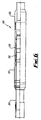
- a sealant material, Teflon ® is located between the ridges 68 to provide an improved seal if the primary metal seal of the ridges 68 fail. This is described with reference to Figure 6 .
- the tool 10 can be retrieved from the well bore, by moving the ends 24,26 apart via movement of one or both of the cones 50,58. Separation of the ends 24,26 pulls the seal longitudinally and the seal 12 returns close to its original shape. A space 14 is thus created between the tool 10 and the casing 18 so that the work string can be pulled from the hole.
- sealing element 112 operates in an identical manner to sealing element 12 in providing a seal between two surfaces.
- ends are shown held in opposed fixings 148a,b as described hereinbefore with reference to figures 1 and 2 .
- Sealing element 112 comprises a continuous cylindrical annulus which may be described as a torus.
- the element 112 is formed from two metal sleeves, a first 120 being arranged inside and coaxial with a second 122.
- the sleeves, 120,122 are joined at upper 124 and lower 126 ends by having adjacent sides of the sleeves meeting over a short distance.
- the ends 124,126 of the sleeves 120,122 are held together by the fixing elements 148a,b.
- a resultant interior volume 130 is created which is entirely bounded by the sleeves 120,122 and the ends 124,126.
- the interior volume 130 is completely filled with a filler 128.
- the filler 128 contacts the sleeves 120,122 and ends 124,126.
- Each sleeve 120, 122 is formed of a metal continuous metal strip.
- the metal is preformed into a shape calculated to deform in a predetermined manner when the ends 124,126 are brought together.
- the inner sleeve 120 in longitudinal cross-section, has a surface 132 which is symmetrically shaped through a horizontal plane equidistant from the ends 124, 126.
- the surface 132 forms a series of peaks and troughs.
- There are two troughs 138a,b which comprise opposing sloping surfaces, bounding a single peak 136 which is a plateau bounded by the sloping surfaces of the troughs 138a,b.
- the outer sleeve 122 has a profile 134 in reverse to the inner sleeve 120 with respect to the element 112.
- peaks 142a,b opposing the troughs 138a,b. These have been levelled to provide a sharp sloping surface into the trough 144 opposite the peak 138.
- Each surface 132,134 is made up of a series of straight sections so that the metal of the sleeve can be bent along fold lines to create the shape required. In longitudinal cross-section through the torus, a polygon is created which defines the interior volume 30 and the volume of filler 128.
- the interior volume 130 remains substantially constant while the shape of the sleeves 120,122 ie. the polygon, deforms in a manner to accentuate the peaks and troughs.
- the filler 128 will deform with the element 112, but will remain in contact with the entire inside surface of the sleeves 120,122 at all times. In this way delamination is prevented which would otherwise cause air pockets in the seal, weakening its ability to withstand both longitudinal pressure applied from the ends 124,126 and transverse pressure applied horizontally between the sleeves 120,122.
- FIG. 4 of the drawings illustrates the seal 112 of Figure 3 when the ends 124,126 have been brought toward each other.
- Like parts to those of Figure 3 have been given the same reference numeral to aid clarity.
- the peaks 142a,b now sit proud of the fixing elements 148a, b.
- the peaks 136,138,142 are plateau like, they provide planar surfaces to improve the sealing properties of the element 112.
- the area of contact of the sealing element 112 is thus predetermined by the dimension of the peaks 136,138,142 in the shape of the original sleeves 120,122.
- the peaks 142a,b on the outer sleeve 122 may include ridge or other material to improve the grip of the sealing element 112 when these positions contact a surface within a well bore. Such additional features are illustrated with reference to Figure 5 .
- Figure 5 shows a part cross-sectional view through the outer sleeve 22 of a sealing element 12. Like parts to those of Figures 1 and 2 have been given the same reference numeral to aid clarity.
- Outer surface 40 of the sleeve 22 has a number of ridges 68a,b located thereon.
- the ridges 68 are protrusions extending from the surface. While they are illustrated as triangular in cross-section, it will be understood that a variety of forms could be used as long as they provide a 'bite' for the seal 12 against the second surface (not shown).
- a sealant material 72 Located between the ridges 68a,b on a portion 70 of the surface is a sealant material 72.
- the material 72 can be a coating or may be a treatment applied to the surface 70.
- the coating could be metal, plastic or another material which will conform to the second surface on contact. While the material 72 is shown as only located between the ridges 68 it will be understood that the ridges could additionally or independently be coated. Teflon ® or the like, would be a suitable material 72.
- a further feature of the surface 40 is in the provision of a groove 74 for an insert 76.
- grooves 74 in the form of indents can be arranged.
- an insert 76 is fitted into each groove 74.
- the insert 76 is a metal, which is preferably a ductile, inert metal, such as gold. In use, the insert 76 would be the primary seal, instead of the outer surface 40 or the sealant material 72. The ductile insert 76 will deform to accommodate any scratches or other discontinuities, which the outer surface 40 may not.
- FIG. 6 illustrates an expansion joint, generally indicated by reference numeral 310, as may be found in a tool string run in a well bore.
- the joint 310 operates by allowing one portion, such as a sleeve 313 to move axially relative to the mandrel 315.
- a seal 312 is located between the moving parts with a pressure differential between the outside and the tubing string.
- the seal 312 is as described hereinbefore with reference to Figures 1-4 .
- the seal 312 is held on a mandrel 315, within a seal bore 317.
- the seal could be held on a housing, with a moveable mandrel.
- the seal 312 is activated by applying a pre-load to deform it slightly.
- a threaded ring 319 is used to apply the pre-load, but other methods could be equally be used.
- the surface of the seal bore 317 is treated in such a manner that friction and wear are minimised. This could be done with tungsten carbide coating or other such methods, which are well understood.
- the seal 312 slides within the seal bore 317, maintaining a dynamic seal during axial movement of the mandrel 315 within the stationary seal bore 317.
- FIGS 7(a) and 7(b) illustrating a sealing element, generally indicated by reference numeral 412, being used as a flange sealing ring.
- a sealing element generally indicated by reference numeral 412
- Each flange 421a,b includes a circular groove 427a,b located on the surface 429a,b of the flange plate 431a,b.
- the seal 412 is sized to locate within the grooves 427a,b. Indeed the grooves 427a,b are profiled to match the outer surface of the ends 424,426 of the seal 412.
- Sealing between the flanges 421a,b is achieved at the first surface, being a combination of the inner edges 433a,b of the grooves 427a,b respectively, and the second surface, being a combination of the outer edges 435a,b of the grooves 427a,b respectively.
- Sealing element 412 is as described with reference to Figures 1-4 , comprising an annular body.
- Element 412 is formed as two concentric metal sleeves, an inner sleeve 420 and an outer sleeve 422.
- the sleeves are joined at upper 424 and lower 426 ends. Joining is by welding of the sleeves 420,422.
- a filler 428 Between the sleeves 420,422 is located a filler 428.
- the filler is entirely contained within the sealing element 412 and bounded on all sides by the metal sleeves 420,422.
- an interior volume 430 defined by the metal sleeves 420,422 contains an equal volume of the filler 428.
- Inner sleeve 420 is geometrically arranged to provide two symmetrical peaks 436a,b running circumferentially around the surface 432.
- a trough 438 lies between the two peaks 436a,6.
- Trough 438 has symmetrical sloping side walls with a flat base 439.
- the outer sleeve 422 has a similar geometrical arrangement on its outer surface 440 to that of the inner surface 432. However peaks 442a,b are somewhat closer together providing a narrower trough 444 without a flat base.
- geometrical arrangement of the sealing element 412 is selected so that when the ends 424,426 are brought together the element 412 will deforms in a controlled manner.
- the peaks 436,442 and troughs 438,444 act like fold lines on the sleeves 420, 422 forming a cantilever structure, which supports the seal.
- the filler 428 supports the seal 412 to prevent the seal from collapsing with pressure applied from the ends 424.
- the interior volume 430 and the volume of the filler 428 remain the same during compression of the seal 412.
- the filler 428 remains in contact with the continuous surface formed by the sleeves 420, 422. Delamination does not occur, thus the filler 428 helps prevent the seal 412 collapsing when pressure is applied across the seal.
- the principal advantage of the present invention is that by entirely enclosing a filler material within two sleeves, volumetric changes in the sealing element are minimised and the seal will deform in a controlled manner.
- a further advantage of an embodiment of the present invention is that it provides a sealing element, which by forming a cantilever structure on deforming, produces a strong seal which can be used to anchor tools in a well bore.
- a yet further advantage of an embodiment of the present invention is that it provides a sealing element which does not collapse under pressure differentials. This is done without the need to thicken the sleeves as it is achieved by the 'rubber pressure' of the filler within the sealing element.
- a still further advantage of an embodiment of the present invention is that it provides a sealing element which does not use elastomers, thus heat and chemicals typically found in well bores will not affect the operation of the seal.
- a still further advantage of an embodiment of the present invention is that it provides a sealing element which has the benefits of flexibility, like an elastomer seal, but is fully metal-to metal.
- a yet further advantage of at least one embodiment of the present invention is that it provides a sealing element which can be used in dynamic applications where it must slide while maintaining a seal.
- the overall size of the sealing element can be varied to suit the tool used.
- the applications describe use in a packer, joint and flange mating but the sealing element could equally be applied to a range of subsea/downhole tools and equipment where a seal and/or anchoring is required.
Abstract
Description
- The present invention relates to seals used between metal surfaces and in particular, though not exclusively, to an annular seal for use in flanges, joints and packers located in oil and gas exploration and production equipment.
- Typical annular seals used to prevent the passage of fluid between two surfaces are elastomeric o-rings. The material makes them flexible enough to mould into any deformities in the metal surface, while their compressibility aids in providing a large sealing area. However, these seals can go beyond their operational limits when used within well bores during oil and gas exploration and production due to the extremes of pressure, temperature and the harsh substances which are used. In order to overcome these problems, metal to metal seals have been developed to provide increased seal strength and reduce seal degradation.
- These metal to metal seals have found application in flanges, for example. When API 6A or similar flanges are manufactured, the groove has an exact geometry and surface finish. The sealing ring is a solid metal ring, which is compressed against the seal ring grooves to make the metal-to-metal seal. This is typically achieved by tightening the bolts on the flange. As there is no or little flexibility in the seal, side loading can reduce or remove any seal formed between the groove and flange. Furthermore, older flanges, which are subject to corrosion, can leak. As there is no compliance within the solid metal ring, once a leak appears the seal cannot be re-seated without re-tightening the bolts. In sub-sea applications, it is very expensive to monitor each flange and tighten the bolts as part of a maintenance programme.
- To overcome this problem, seals incorporating the strength of metals together with the flexible characteristics of elastomers have been developed.
EP 1136734 ,DE 3633335 andDE 3712814 all disclose flange ring seals using metal and elastomeric parts. These seals generally comprise a metal insert in the elastomeric material. While this design provides a seal with improved rigidity, the seal against the flange is made by the elastomer, which has the inherent disadvantage of seal degradation. - In packers, it is known to position an elastomeric sleeve around a tubing, the sleeve being limited by upper and lower retainers. In order to provide an annular seal and/or anchor the tubing in a well bore, one or both of the retainers are moved toward the other. This results in compression of the sleeve so that it deforms radially outwardly to fill the space between the tubing and a bore hole wall or tubular and adhere to the bore hole wall or tubular. Various arrangements have been provided in an attempt to ensure a sufficient portion of the sleeve contacts the borehole or tubular wall to effect a good seal while maintaining the sleeve within the retainers during compression. In addition, the surface of the seals have been modified to improve adhesion to the borehole wall. Further, metal to metal seals as described above, have been incorporated.
-
WO 02/04783 to Moyes -
US-5,988,276 to Oneal discloses a compact retrievable well packer which also utilises deformable cylindrical members to form the annular seal and also to lock the well packer in situ. As with Moyes, thick sections are required to prevent the sealing element from collapsing under pressure differentials. -
US 5,961,123 to Ingram et al discloses a seal arrangement which is designed to prevent the seal from extruding uphole or downhole when subjected to extremes of differential pressure. In this arrangement the seal material is bounded at either end by metal back-up rings, these rings may be attached to the seal or, as disclosed inUS 5,961,123 , be attached to one of the retainers. This seal has the typical disadvantages of elastomeric based seals which can be degraded easily by heat and chemicals used downhole. -
US 5,775,429 to Arizmendi et al discloses a seal including a deformable sheath having a body and first and second ends for defining an interior volume proximate to a tool surface. The tool surface is the tubing. A material located within the interior volume is deformable, when the sheath second end is moved toward the sheath first end. The sheath is typically a relatively thin walled tubular member formed from materials like stainless steel or titanium. The filler material within the interior volume plastically deforms to advantageously allow the seal to be used oval shaped bore holes. Unfortunately this seal does not perform well in practice. As the filler material is restrained by the tubing, volumetric changes in the seal distort the seal and reduce the effectiveness of contact with the bore hole wall or tubular. These volumetric changes occur as the sheath ends are brought together before the seal meets the bore hole wall or tubular and is pressurised. -
US 2002/0166672 discloses a further related seal having a deformable portion made of e.g. metal, and a filler that is, preferably, compressible. Furthermore,US 3,147,016 discloses a flange ring seal comprising a hollow deformable annular casing and a liquid filling this casing. - It is an object of at least one embodiment of the present invention to provide a sealing element which is flexible, like an elastomer seal, but is fully metal to metal.
- It is a further object of at least one embodiment of the present invention to provide a sealing element having a fully enclosed filler material to provide improved sealing properties of the element.
- It is a yet further object of at least one embodiment of the present invention to provide a sealing element which deforms in a controlled manner on a cantilever principle.
- According to a first aspect of the present invention there is provided a sealing element for providing a seal between a first and a second surface as defined by claim 1. The element comprising an inner deformable surface, an outer deformable surface, the inner and outer surfaces being joined at opposed first and second ends, providing a body defining an interior volume entirely bounded by the said surfaces and said ends, a deformable filler material within said interior volume, wherein the element deforms in a predetermined manner to seal between the first and second surfaces when said ends are brought toward each other.
- By entirely enclosing the deformable filler material within the element, the material acts as a filler within a continuous body. This allows the shape of the volume of the element to change as the ends are brought together but minimises any change in the said interior volume. By minimising any change in the interior volume until pressure is applied across the seal, the seal will deform in a predetermined manner. As discussed hereinbefore, as a disadvantage with respect to the seal of
US 5,775,429 , delamination of the filler from the said surfaces will occur unless the volume change is minimised. This feature of the seal helps prevent the seal collapsing when pressure is applied across the seal, between the inner and outer surfaces. - The inner and outer deformable surfaces are sleeves, the element whereby being annular. Such an arrangement can provide a seal around a mandrel or tubing. Alternatively the arrangement can provide an annular seal for a flange. The inner and outer surfaces are deformable metal sleeves. Preferably the inner and outer surfaces define a first shape containing the interior volume. Following reformation the inner and outer surface define a second shape. Preferably the second shape is a cantilever structure arranged longitudinally between the ends. Preferably the first and second shapes are predetermined. The first and second shapes may be annular having a polygon in longitudinal cross-section. Advantageously the polygon is symmetrical across the horizontal plane. In a first embodiment the polygon has ten sides. In a preferred embodiment the polygon has fifteen sides. The shape of the polygon, but not the number of sides, varies as the sealing element is deformed. Preferable the outer surface defines at least two peaks and at least one trough. Preferably also the inner surface defines at leas two peaks and at least one trough. In a preferred embodiment the outer surface defines two peaks and one trough and the inner surface defines three peaks and two troughs.
- The deformable filler material has a first volume. Advantageously the first volume equals the interior volume and both remain substantially equal as the ends are brought together. The deformable filler material may be an elastomer, plastic or other flexible material. Advantageously the filler material is a plastic. Use of a plastic is possible as the filler material will allow the seal to have a higher temperature rating than an elastomer, but being entirely encased in metal will not extrude as can be seen with elastomers and such plastics which have unsuitable mechanical properties.
- Preferably the outer surface includes a plurality of outer ridges. The outer ridges bite into the second surface. The is advantageous when the second surface is a wall of the well bore, in a well which is open hole, or a tubing wall for a well which is cased. Preferably the outer ridges are arranged circumferentially around the outer surface. Advantageously a sealant material is applied to at least a portion of the outer surface. More preferably the portion is between the outer ridges. The sealant material may be Teflon® or the like. The sealant material provides a seal in the event that the primary metal seal of the outer surface fails to work.
- Optionally at least one metal insert is located on at least a portion of the outer surface. More preferably the portion is between the outer ridges. Preferably the metal insert is a ductile inert metal. More preferably, the metal insert is gold. The metal insert could be the primary seal, instead of the deformable surfaces or the sealant material. The ductile insert could deform to accommodate any scratches or other discontinuities, which the outer surface may not.
- According to a second aspect of the present invention there is provided a method of providing a seal between a first and a second surface as defined by claim 13. The method comprises the steps:
- (a) providing a sealing element according to the first aspect, having a first interior volume and a first shape with a filler having a first volume substantially equal to the first interior volume;
- (b) arranging the element adjacent the first surfaces and opposite the second surface;
- (c) moving one or both ends of the sealing element toward the opposing end;
- (d) deforming the sealing element in a controlled manner to provide a second shape while keeping the first interior volume and the first volume substantially equal;
- (e) contacting the sealing element on the first and second surfaces to provide the seal; and
- (f) further moving one or both ends of the sealing element toward the opposing end to provide a pressure across the sealing element between the inner and outer surfaces.
- By keeping the volumes substantially equal, delamination of the filler material from the inner and outer surfaces is prevented. By avoiding delamination this helps prevent the sealing element collapsing when the pressure is applied across the sealing element in step (f).
- Preferably, the sealing element forms a cantilever structure during deformation.
- Preferably the method includes the step of deforming the outer and inner surfaces of the sealing element.
- Preferably also the method includes the step of abutting ridges of the sealing element onto at least the second surface. Advantageously the step includes the ridges biting into the second surface.
- Preferably the method further includes the step of abutting a sealing material of the sealing element to at least the second surface to improve the sealing characteristics.
- Preferably the method further includes the step of abutting a metal insert of the sealing element to at least the second surface to improve the sealing characteristics.
- According to a third aspect of the present invention there is provided apparatus for providing a seal between a first and a second surface within in a well bore in accordance with claim 19. The apparatus comprises a substantially tubular body upon which is located the first surface; a sealing element according to the first aspect and located around the tubular body, comprising an inner deformable surface, an outer deformable surface, the inner and outer surfaces being joined at opposed first and second ends, providing a sealing body defining as interior volume entirely bounded by the said surfaces and said ends, a deformable filler material within said interior volume; at least one actuating element arranged around and longitudinally moveable relative to the body; the actuating element including means for affixing an end of the sealing element; wherein the sealing element deforms in a predetermined manner to seal between the first and second surfaces when said ends are brought toward each other by movement of the actuating element.
- Preferably the apparatus comprises a packer or other downhole tool. More preferably the apparatus comprises a retrievable packer. Alternatively the apparatus comprises an expansion joint or other travelling seal.
- Preferably the at least one actuating element is a cone. The cone having a bore therethrough for passage of the sealing body. Preferably there are two cones, one located at each end of the sealing element. Preferably also at least one cone is releasably retained to the tubular body. The cone may be retained by shear pins.
- Alternatively the at least one actuating element is a threaded ring. By tightening the ring against an end, the sealing element is pre-loaded.
- The inner and outer deformable surfaces are sleeves, the element thereby being annular. Such an arrangement provides a seal around a mandrel or tubing. The inner and outer surfaces are deformable metal sleeves. Preferably the inner and outer surfaces define a first shape containing the interior volume. Following deformation the inner and outer surface define a second shape. Preferably the second shape is a cantilever structure arranged longitudinally between the ends. Preferably the first and second shapes are predetermined. The first and second shapes may be annular having a polygon in longitudinal cross-section. Advantageously the polygon is symmetrical on the across the horizontal plane. In a first embodiment the polygon has ten sides. In a preferred embodiment the polygon has fifteen sides. The shape of the polygon, but not the number of sides, varies as the sealing element is deformed. Preferable the outer surface defines at least two peaks and at least one trough. Preferably also the inner surface defines at least two peaks and at least-one trough. In a preferred embodiment the outer surface defines two peaks and one trough and the inner surface defines three peaks and two troughs.
- The deformable filler material has a first volume. Advantageously the first volume equals the interior volume and both remain substantially equal as the ends are brought together. The deformable filler material may be an elastomer or a plastic. Advantageously the filler material is a plastic. Use of a plastic is possible as the filler material will not be affected by heat, being entirely encased in metal.
- Preferably the outer surface includes a plurality of outer ridges. The outer ridges bite into the second surface in the well bore. The second surface may be a wall of the well bore, when the well is open hole, or tubing wall when the well is cased. Preferably the outer ridges are arranged circumferentially around the outer surface. Advantageously a sealant material is applied to at least a portion of the outer surface. More preferably the portion is between the outer ridges. The sealant material may be Teflon® or the like. The sealant material provides a seal in the event that the primary metal seal of the outer surface fails to work.
- Optionally at least one metal insert is located on art least a portion of the outer surface. More preferably the portion is between the outer ridges. Preferably the metal insert is a ductile inert metal. More preferably, thy metal insert is gold. The metal insert, could be the primary seal, instead of the deformable surfaces or the sealant material. The ductile insert could deform to accommodate any scratches or other discontinuities, which the outer surface may not.
- According to a fourth aspect of the present invention there is provided a method of anchoring an apparatus to an inner surface of a well bore as defined by
claim 22. The method comprises the steps: - (a) providing an apparatus according to the third aspect, having a first interior volume and a first shape with a filler having a first volume substantially equal to the first interior volume;
- (b) running the apparatus on a work string in the well bore;
- (c) moving one or both ends of the sealing element according to the first aspect, toward the opposing end;
- (d) deforming the sealing element in a controlled manner to provide a second shape while keeping the first interior volume and the first volume substantially equal;
- (e) contacting the sealing element on the first and second surfaces; and
- (f) further moving one or both ends of the sealing element toward the opposing end to provide a pressure across the sealing element between the inner and outer surfaces thereby anchoring the apparatus to the second surface.
- Preferably, the sealing element forms a cantilever structure during deformation.
- Preferably the method includes the step of deforming the outer and inner surfaces of the sealing element.
- Preferably also the method includes the step of abutting ridges of the sealing element onto the second surface. Advantageously the step includes the ridges biting into the second surface.
- Preferably the method further includes the step of abutting a sealing material of the sealing element to the second surface to improve the sealing characteristics.
- According to a fifth aspect of the present invention there is provided a flange ring seal as defined by claim 23 for location in a groove of a mating plate of a flange, the seal in accordance with the first aspect and comprising an inner deformable surface, an outer deformable surface, the inner and outer surfaces being joined at opposed first and second ends, providing a sealing body defining an interior volume entirely bounded by the said surfaces and said ends, a deformable filler material within said interior volume; wherein an end is adapted to be arranged to locate in the groove of the flange and wherein the seal deforms in a predetermined manner an opposing mating plate is brought against the mating plate to seal between the plates.
- The inner and outer deformable surfaces are sleeves, thus forming the ring. The inner and outer surfaces are deformable metal sleeves. Preferably the inner and outer surfaces define a first shape containing the interior volume. Following deformation the inner and outer surface define a second shape. Preferably the second shape is a cantilever structure arranged longitudinally between the ends. Preferably the first and second shapes are predetermined. The first and second shapes may be annular having a polygon in longitudinal cross-section. Advantageously the polygon is symmetrical on the across the horizontal plane. In a first embodiment the polygon has ten sides. In a preferred embodiment the polygon has fifteen sides. The shape of the polygon, but not the number of sides, varies as the sealing element is deformed. Preferable the outer, surface defines at least two peaks and at least one trough. Preferably also the inner surface defines at least two peaks and at least one trough. In a preferred embodiment the outer surface defines two peaks and one trough and the inner surface defines three peaks and two troughs.
- The deformable filler material has a first volume. Advantageously the first volume equals the interior volume and both remain substantially equal as the ends are brought together. The deformable filler material may be an elastomer or a plastic. Advantageously the filler material is a plastic. Use of a plastic is possible as the filler material will not be affected by heat, being entirely encased in metal.
- Embodiments of the present invention will now be described, by way of example only, with reference to the following drawings of which:
-
Figure 1 is a cross-sectional view a packer tool incorporating a sealing element according to an embodiment of the present invention, with the element unset; -
Figure 2 is a cross-sectional view through the tool ofFigure 1 , now shown in the set position; -
Figure 3 is a cross-sectional view a packer tool incorporating a sealing element according to a further embodiment of the present invention, with the element unset; -
Figure 4 is a cross-sectional view through the tool ofFigure 4 , now shown in the set position; -
Figure 5 is a part cross-sectional view of a portion of the outer surface of a sealing element according to a further embodiment of the present invention; -
Figure 6 is a part cross-sectional view of an expansion joint incorporating a sealing element according to a further embodiment of the present invention; and -
Figure 7(a) is a schematic cross-sectional view through mating flanges incorporating a sealing element, shown in detail inFigure 7(b) , according to a further embodiment of the present invention. - Referring initially to
Figure 1 , there is illustrated a downhole tool, generally indicated byreference numeral 10, according to an embodiment of the present invention. -
Downhole tool 10 is a packer, being an apparatus for providing a seal between a first and a second surface within in a well bore. Located on thetool 10, is a sealingelement 12, according to an embodiment of the present invention.Tool 10 operates by filling thespace 14 between the tool body 16 and a bore hole wall, such as a casing 18, to provide a seal between thetool 10 and the casing 18. - Sealing
element 12 comprises a generally cylindrical sleeve which surrounds the tool body 16.Element 12 is formed as two concentric metal sleeves, aninner sleeve 20 and anouter sleeve 22. The sleeves are joined at upper 24 and lower 26 ends. Between thesleeves filler 28. The filler is entirely contained within the sealingelement 12 and bounded on all sides by themetal sleeves interior volume 30 defined by themetal sleeves filler 28. - The
sleeves sleeve ends filler 28 is also of a deformable material. The filler may be a plastic or elastomer. However, as thefiller 28 is entirely encased in metal, it is not affected by heat and thus a plastic, such as Teflon®, is preferable. - The
inner sleeve 20 provides aninner surface 32 facing anouter surface 34 of the tool body 16.Inner surface 20 is geometrically arranged to provide twosymmetrical peaks 36a,b running circumferentially around thesurface 20.Peaks 36a,b rest on thesurface 34 of the tool body 16. Atrough 38 lies between the twopeaks Trough 38 has symmetrical sloping side walls with a flat base flying parallel to thesurface 34 of the tool body 16. - The
outer sleeve 22 has a similar geometrical arrangement on itsouter surface 40 to that of theinner surface 32. However peaks 42a,b are somewhat closer together providing anarrower trough 44. The bases of eachtrough - When viewed together in cross-section, the
surfaces element 12 is selected so that when the ends 24,26 are brought together theelement 12 will deform in a controlled manner. The peaks 36,42 andtroughs sleeves element 12 will form a cantilever structure, best seen inFigure 2 . - In
Figure 2 , the ends 24,26 have been brought together by the longitudinal displacement of theend 24 towards theelement 12.Trough 38 has been forced radially outwards and meetstrough 44. With thesleeves chambers 46a,b. The peaks 36,42 are now more acute so that theelement 12 bridges the space. It should be noted that theelement 12 provides a cantilever structure which supports theseal 12 and allows thetool 10 to be anchored to the casing 18 by theslips 66. Thefiller 28 supports theseal 12 to prevent the seal from collapsing with pressure applied from theend 24. Theinterior volume 30 and the volume of thefiller 28 remain substantially the same between the two positions,Figure 1 and Figure 2 . Thefiller 28 has remained in contact with the continuous surface formed by thesleeves anterior volume 30. As delamination has not occurred, thefiller 28 helps prevent theseal 12 collapsing when pressure is applied across the seal between thesurfaces seal 12 is in contact with the casing 18. - Returning to
Figure 1 , sealingelement 12 is mounted upon tool body 16. The ends 24,26 locate into opposedfixings 48a,b. Thefixings 48a,b hold thesleeves interior volume 30 where thefiller 28 is located. At theupper end 24 of theseal 12 is located anupper cone 50, which is formed as a sleeve having a slopingsurface 54.Cone 50 fits over the tool body 16 and is held against the body byshear pins 52a,b. Thecone 50 has an outersloping section 54 and alower lip 56.Lip 56 provides an overhang across theseal 12 and theseal 12 rests upon it. Thelip 56 covers the fitting 48a, thereby protecting theend 24 of the seal during operation. - At the
lower end 26 of theseal 12 is located alower cone 58.Cone 58 includes a slopingsurface 60 and alip 62 in an identical manner tocone 50.Cone 58 is bolted to the tool body 16 so that it cannot move during operation of thetool 10. Located outside thecones slips 64,66 as are known in the art. - In use,
tool 10 is mounted on a work string (not shown) and run into a well bore. Theseal 12 is not set, as illustrated inFigure 1 , so thatseal 12 lies toward the body 16 and aspace 14 exits between thetool 10 and the casing 18 within the well bore. In this unset configuration thetool 10 can be run without interfering with any other operations performed in the well bore. When thetool 10 has reached a location within the well bore where an annular seal is required between thetool 10 and the casing, thetool 10 can be set. This is achieved by moving thecone 50 towards thelower sleeve 58. It will be appreciated by those skilled in the art that either or bothcones cone 50. Shear pins 52a,b are sheared in the actuation to allow thecone 50 to move along the tool body 16. Ifcone 50 is the lower cone, then holding the cone in position will provide actuation by the relative movement of the work string and thetool 10 through the cone. - Effectively,
cone 50 its moved towardssleeve 58. The compression applies pressure longitudinally onto theseal 12. The pressure causes the peaks 36,42 to move away from each other while thetroughs seal 12 to deform in this controlled manner. Deformation is complete when the troughs meet. This is illustrated inFigure 2 . During the deformation, the polygon has changed in shape, but theinterior volume 30 and the volume of thefiller 28 have remained substantially equal and constant throughout. - Continued pressure forces the outer peaks 42 against the
casing 38 while the inner peaks meet thesurface 34 of the tool body 16. A seal is thus formed between the tool 16 and thecasing 38. Additionally theseal 12 now anchors thetool 10 against thecasing 38 at this location. Theseal 12 is set. Theseal 12 provides a cantilever structure from the overhangs atlips filler 28 located now in the twochambers 46a,b supports the seal and prevents any collapsing as additional force is applied from thecone 50, and across the seal from the casing 18.Slips 64,66 have been forced up theslopes tool 10. - Sealing
element 12 hasridges 68 located upon itsouter surface 40. Theridges 68 bite into thecasing 38 in order to effect the seal. A sealant material, Teflon®, is located between theridges 68 to provide an improved seal if the primary metal seal of theridges 68 fail. This is described with reference toFigure 6 . - The
tool 10 can be retrieved from the well bore, by moving theends cones ends seal 12 returns close to its original shape. Aspace 14 is thus created between thetool 10 and the casing 18 so that the work string can be pulled from the hole. - Referring now to
Figure 3 , there is illustrated a sealing element, generally indicated byreference numeral 112, according to a preferred embodiment of the present invention. Like parts to the sealingelement 12 offigures 1 and 2 have been given the same reference numeral with the addition of one hundred.Sealing element 112 operates in an identical manner to sealingelement 12 in providing a seal between two surfaces. For ease of interpretation, ends are shown held in opposedfixings 148a,b as described hereinbefore with reference tofigures 1 and 2 . -
Sealing element 112 comprises a continuous cylindrical annulus which may be described as a torus.. Theelement 112 is formed from two metal sleeves, a first 120 being arranged inside and coaxial with a second 122. The sleeves, 120,122 are joined at upper 124 and lower 126 ends by having adjacent sides of the sleeves meeting over a short distance. The ends 124,126 of the sleeves 120,122 are held together by the fixingelements 148a,b. A resultantinterior volume 130 is created which is entirely bounded by the sleeves 120,122 and the ends 124,126. Theinterior volume 130 is completely filled with afiller 128. Thefiller 128 contacts the sleeves 120,122 and ends 124,126. Eachsleeve inner sleeve 120, in longitudinal cross-section, has asurface 132 which is symmetrically shaped through a horizontal plane equidistant from theends surface 132 forms a series of peaks and troughs. There are twotroughs 138a,b which comprise opposing sloping surfaces, bounding asingle peak 136 which is a plateau bounded by the sloping surfaces of thetroughs 138a,b. Theouter sleeve 122 has aprofile 134 in reverse to theinner sleeve 120 with respect to theelement 112. There are notdistinct peaks 142a,b, opposing thetroughs 138a,b. These have been levelled to provide a sharp sloping surface into thetrough 144 opposite the peak 138. Each surface 132,134 is made up of a series of straight sections so that the metal of the sleeve can be bent along fold lines to create the shape required. In longitudinal cross-section through the torus, a polygon is created which defines theinterior volume 30 and the volume offiller 128. - By mirroring the profiles of the sleeves 120,122, when the ends 124,126 are brought together the
interior volume 130 remains substantially constant while the shape of the sleeves 120,122 ie. the polygon, deforms in a manner to accentuate the peaks and troughs. As theinterior volume 130 remains substantially constant thefiller 128 will deform with theelement 112, but will remain in contact with the entire inside surface of the sleeves 120,122 at all times. In this way delamination is prevented which would otherwise cause air pockets in the seal, weakening its ability to withstand both longitudinal pressure applied from the ends 124,126 and transverse pressure applied horizontally between the sleeves 120,122. - Reference is now made to
Figure 4 of the drawings which illustrates theseal 112 ofFigure 3 when the ends 124,126 have been brought toward each other. This represents theseal 112 in the 'set' position. Like parts to those ofFigure 3 have been given the same reference numeral to aid clarity. It can be seen that thepeaks 142a,b now sit proud of the fixingelements 148a, b. As the peaks 136,138,142 are plateau like, they provide planar surfaces to improve the sealing properties of theelement 112. The area of contact of the sealingelement 112 is thus predetermined by the dimension of the peaks 136,138,142 in the shape of the original sleeves 120,122. Further the arrangement of opposing peaks and trough, with atrough 144/peak 136 on the horizontal plane bounded by symmetrically arranged peaks 142 and troughs 138, provides a cantilever structure which strengthens the sealingelement 112. - As described herein with reference to
figures 1 and 2 thepeaks 142a,b on theouter sleeve 122 may include ridge or other material to improve the grip of the sealingelement 112 when these positions contact a surface within a well bore. Such additional features are illustrated with reference toFigure 5 . -
Figure 5 shows a part cross-sectional view through theouter sleeve 22 of a sealingelement 12. Like parts to those ofFigures 1 and 2 have been given the same reference numeral to aid clarity.Outer surface 40 of thesleeve 22 has a number ofridges 68a,b located thereon. Theridges 68 are protrusions extending from the surface. While they are illustrated as triangular in cross-section, it will be understood that a variety of forms could be used as long as they provide a 'bite' for theseal 12 against the second surface (not shown). - Located between the
ridges 68a,b on aportion 70 of the surface is asealant material 72. The material 72 can be a coating or may be a treatment applied to thesurface 70. The coating could be metal, plastic or another material which will conform to the second surface on contact. While thematerial 72 is shown as only located between theridges 68 it will be understood that the ridges could additionally or independently be coated. Teflon® or the like, would be asuitable material 72. - A further feature of the
surface 40 is in the provision of agroove 74 for aninsert 76. At discrete locations over thesurface 40,grooves 74 in the form of indents can be arranged. Into eachgroove 74 aninsert 76 is fitted. It will be appreciated that any suitable technique may be used for attaching theinsert 76 to thegroove 74. Theinsert 76 is a metal, which is preferably a ductile, inert metal, such as gold. In use, theinsert 76 would be the primary seal, instead of theouter surface 40 or thesealant material 72. Theductile insert 76 will deform to accommodate any scratches or other discontinuities, which theouter surface 40 may not. - A further example application of use of the sealing element of the present invention, is in an expansion joint.
Figure 6 illustrates an expansion joint, generally indicated byreference numeral 310, as may be found in a tool string run in a well bore. The joint 310 operates by allowing one portion, such as asleeve 313 to move axially relative to themandrel 315. Aseal 312 is located between the moving parts with a pressure differential between the outside and the tubing string. Theseal 312 is as described hereinbefore with reference toFigures 1-4 . Theseal 312 is held on amandrel 315, within aseal bore 317. Alternatively, the seal could be held on a housing, with a moveable mandrel. Theseal 312 is activated by applying a pre-load to deform it slightly. A threadedring 319 is used to apply the pre-load, but other methods could be equally be used. The surface of the seal bore 317 is treated in such a manner that friction and wear are minimised. This could be done with tungsten carbide coating or other such methods, which are well understood. In use, theseal 312 slides within the seal bore 317, maintaining a dynamic seal during axial movement of themandrel 315 within the stationary seal bore 317. - Reference is now made to
Figures 7(a) and7(b) , illustrating a sealing element, generally indicated byreference numeral 412, being used as a flange sealing ring. Whenflanges 421a,b are brought together to join adjacent pipe sections 423a,b, a seal is needed to prevent the escape of fluid from the pipe bore 425. Eachflange 421a,b includes acircular groove 427a,b located on thesurface 429a,b of theflange plate 431a,b. Theseal 412 is sized to locate within thegrooves 427a,b. Indeed thegrooves 427a,b are profiled to match the outer surface of the ends 424,426 of theseal 412. Sealing between theflanges 421a,b is achieved at the first surface, being a combination of theinner edges 433a,b of thegrooves 427a,b respectively, and the second surface, being a combination of theouter edges 435a,b of thegrooves 427a,b respectively. -
Sealing element 412 is as described with reference toFigures 1-4 , comprising an annular body.Element 412 is formed as two concentric metal sleeves, aninner sleeve 420 and an outer sleeve 422. The sleeves are joined at upper 424 and lower 426 ends. Joining is by welding of the sleeves 420,422. Between the sleeves 420,422 is located afiller 428. The filler is entirely contained within the sealingelement 412 and bounded on all sides by the metal sleeves 420,422. Thus an interior volume 430 defined by the metal sleeves 420,422 contains an equal volume of thefiller 428. -
Inner sleeve 420 is geometrically arranged to provide twosymmetrical peaks 436a,b running circumferentially around the surface 432. A trough 438 lies between the twopeaks flat base 439. The outer sleeve 422 has a similar geometrical arrangement on its outer surface 440 to that of the inner surface 432. However peaks 442a,b are somewhat closer together providing anarrower trough 444 without a flat base. - As is seen in
Figures 7(a) and (b) geometrical arrangement of the sealingelement 412 is selected so that when the ends 424,426 are brought together theelement 412 will deforms in a controlled manner. The peaks 436,442 and troughs 438,444 act like fold lines on thesleeves 420, 422 forming a cantilever structure, which supports the seal. Thefiller 428 supports theseal 412 to prevent the seal from collapsing with pressure applied from the ends 424. The interior volume 430 and the volume of thefiller 428 remain the same during compression of theseal 412. Thefiller 428 remains in contact with the continuous surface formed by thesleeves 420, 422. Delamination does not occur, thus thefiller 428 helps prevent theseal 412 collapsing when pressure is applied across the seal. - The principal advantage of the present invention is that by entirely enclosing a filler material within two sleeves, volumetric changes in the sealing element are minimised and the seal will deform in a controlled manner.
- A further advantage of an embodiment of the present invention is that it provides a sealing element, which by forming a cantilever structure on deforming, produces a strong seal which can be used to anchor tools in a well bore.
- A yet further advantage of an embodiment of the present invention is that it provides a sealing element which does not collapse under pressure differentials. This is done without the need to thicken the sleeves as it is achieved by the 'rubber pressure' of the filler within the sealing element.
- A still further advantage of an embodiment of the present invention is that it provides a sealing element which does not use elastomers, thus heat and chemicals typically found in well bores will not affect the operation of the seal.
- A still further advantage of an embodiment of the present invention is that it provides a sealing element which has the benefits of flexibility, like an elastomer seal, but is fully metal-to metal.
- A yet further advantage of at least one embodiment of the present invention is that it provides a sealing element which can be used in dynamic applications where it must slide while maintaining a seal.
- It will be appreciated by those in the art that various modifications may be made to the invention herein described without departing from the scope thereof, the invention being limited by the terms of the appended claims. For example, the overall size of the sealing element can be varied to suit the tool used. The applications describe use in a packer, joint and flange mating but the sealing element could equally be applied to a range of subsea/downhole tools and equipment where a seal and/or anchoring is required.
Claims (23)
- An annular sealing element (12) for providing a seal between a first '(34) and a second surface, the element, characterised in that it comprises an inner sleeve (20) providing an inner deformable surface, an outer sleeve (22) providing an outer deformable surface, the inner and outer sleeves being joined at opposed first (24) and second (26) ends providing a body defining an interior volume (30) entirely bounded by the said surfaces and said ends, and a deformable filler material (28) within said interior volume, the inner and outer sleeves (20, 22) being deformable metal sleeves;
wherein the inner and outer sleeves (20,22) each comprise a plurality of fold lines (36,38,42,44); and wherein the element (12) deforms in a predetermined manner when said ends (24, 26) are brought toward each other by deformation of the inner and outer sleeves about their respective fold lines, to thereby seal between the first (34) and second surfaces. - A sealing element as claimed in claim 1, wherein the ends of the inner and outer sleeves (20,22) are located in abutment and held together by respective fixing elements.
- A sealing element (12) as claimed in either of Claims 1 or 2, wherein the inner and outer sleeves (20, 22) contain the deformable filler (28) when said ends (24,26) of the sleeves are brought toward each other.
- A sealing element (12) as claimed in any preceding Claim, wherein the filler (28) is adapted to prevent the sealing element (12) collapsing when pressure is applied across the seal.
- A sealing element (12) as claimed in any preceding Claim wherein the inner and outer sleeves (20, 22) define a first shape containing the interior volume (30), and wherein following deformation the inner and outer sleeves (20, 22) define a second shape, and further wherein the second shape is a cantilever structure arranged longitudinally between the ends (24, 26).
- A sealing element (12) as claimed in Claim 5 wherein the first and second shapes are annular having a polygon in longitudinal cross-section.
- A sealing element (12) as claimed in Claim 6 wherein the polygon is symmetrical about a horizontal plane, equidistant from the ends (24, 26).
- A sealing element (12) as claimed in any preceding Claim wherein the deformable filler material (28) has a first volume which equals the interior volume (30) and both volumes remain substantially equal as the ends (24, 26) are brought together.
- A sealing element (12) as claimed in any preceding Claim wherein the deformable filler material (28) is a plastic.
- A sealing element (12) as claimed in any preceding Claim wherein the outer surface includes a plurality of outer ridges (68).
- A sealing element (12) as claimed in any preceding Claim wherein a sealant material is applied to at least a portion of the outer surface (40).
- A sealing element (12) as claimed in any preceding Claim wherein at least one metal insert (76) is located in at least a portion of the outer surface.
- A method of providing a seal between a first (34) and a second surface, the method comprising the steps of:(a) providing a sealing element (12) according to any one of Claims 1 to 12, wherein the sealing element (12) has a first interior volume (30) and a first shape, and wherein the filler (28) has a first volume substantially equal to the first interior volume;(b) arranging the element (12) adjacent the first surface (34) and opposite the second surface;(c) moving one or both ends (24, 26) of the sealing element (12) toward the opposing end (24, 26);(d) deforming the sealing element (12) in a controlled manner to provide a second shape while keeping the first interior volume (30) and the first volume substantially equal;(e) contacting the sealing element (12) on the first (34) and second surfaces to provide the seal; and(f) further moving one or both ends (24, 26) of the sealing element (12) toward the opposing end (24, 26) to provide a pressure across the sealing element (12) between the inner and outer surfaces (32, 34).
- A method as claimed in Claim 13 wherein the sealing element (12) forms a cantilever structure during deformation.
- A method as claimed in Claim 13 or 14 wherein the method includes the step of deforming the outer and inner sleeves (22, 20) of the sealing element (12).
- A method as claimed in any one of Claims 13 to 15 wherein the method includes the step of abutting ridges (68) of the sealing element (12) onto at least the second surface.
- A method as claimed in any one of Claims 13 to 16 wherein the method includes the step of abutting a sealing material (72) of the sealing element (12) to at least the second surface.
- A method as claimed in any one of Claims 13 to 17 wherein the method includes the step of abutting a metal insert (76) of the sealing element (12) to at least the second surface.
- Apparatus (10) for providing a seal between a first (34) and a second surface within a well bore, the apparatus comprising:a substantially tubular body (16) upon which is located the first surface (34); characterised bya sealing element (12) according to any of claims 1 to 12 located around the tubular body (16);at least one actuating element (50, 58) arranged around and longitudinally moveable relative to the tubular body (16), the actuating element (50, 58)including means (54, 56; 60, 62) for contacting an end (24, 26) of the sealing element (12);wherein the sealing element (12) deforms in the predetermined manner to seal between the first (34) and second surfaces when said ends (24, 26) are brought toward each other by movement of the actuating element (50, 58).
- Apparatus (10) as claimed in Claim 19 wherein the at least one actuating element (50, 58) is a cone, the cone having a bore therethough for passage of the tubular body (16).
- Apparatus (10) as claimed in Claim 19 wherein the at least one actuating element (50, 58) is a threaded ring.
- A method as claimed in any one of claims 13 to 18, wherein the method is a method of anchoring an apparatus (10) to an inner surface of a well bore and providing a seal between the first (34) and second surfaces, the inner surface of the well bore defining the second surface; and wherein the step of providing the sealing element (12) comprises providing an apparatus (10) according to any one of claims 19 to 21 including the sealing element (12) according to any one of Claims 1 to 12; and wherein the step of arranging the element (12) adjacent the first surface (34) and opposite the second surface comprises running the apparatus (10) on a work string in the well bore and so arranging the element (12); and further wherein the step of further moving one or both ends (24, 26) of the sealing element (12) toward the opposing end (24, 26) also anchors the apparatus (10) to the second surface.
- A flange ring seal (412) for location in a groove (427a,b) of a mating plate (431a,b) of a flange for sealing between a first surface defined by the mating plate (431a,b) and a second surface defined by an opposing mating plate (431a,b), characterised in that the flange ring seal (412) comprises a sealing element as claimed in any one of claims 1 to 12, wherein an end (424, 426) is adapted to be arranged to locate in the groove (427a,b) of the mating plate (431a,b) of the flange and wherein the seal (412) is deformed in the predetermined manner when the opposing mating plate (431a,b) is brought against the mating plate (431a,b), to seal between the plates.
Applications Claiming Priority (2)
| Application Number | Priority Date | Filing Date | Title |
|---|---|---|---|
| GBGB0320252.0A GB0320252D0 (en) | 2003-08-29 | 2003-08-29 | Improved seal |
| PCT/GB2004/003631 WO2005022012A1 (en) | 2003-08-29 | 2004-08-26 | Improved seal |
Publications (2)
| Publication Number | Publication Date |
|---|---|
| EP1660795A1 EP1660795A1 (en) | 2006-05-31 |
| EP1660795B1 true EP1660795B1 (en) | 2008-12-31 |
Family
ID=28686548
Family Applications (1)
| Application Number | Title | Priority Date | Filing Date |
|---|---|---|---|
| EP04768187A Active EP1660795B1 (en) | 2003-08-29 | 2004-08-26 | Improved seal |
Country Status (8)
| Country | Link |
|---|---|
| US (3) | US8186685B2 (en) |
| EP (1) | EP1660795B1 (en) |
| AT (1) | ATE419484T1 (en) |
| CA (2) | CA2537153C (en) |
| DE (1) | DE602004018790D1 (en) |
| GB (1) | GB0320252D0 (en) |
| NO (1) | NO334599B1 (en) |
| WO (1) | WO2005022012A1 (en) |
Families Citing this family (93)
| Publication number | Priority date | Publication date | Assignee | Title |
|---|---|---|---|---|
| US7779903B2 (en) * | 2002-10-31 | 2010-08-24 | Weatherford/Lamb, Inc. | Solid rubber packer for a rotating control device |
| US9682425B2 (en) | 2009-12-08 | 2017-06-20 | Baker Hughes Incorporated | Coated metallic powder and method of making the same |
| GB0320252D0 (en) * | 2003-08-29 | 2003-10-01 | Caledyne Ltd | Improved seal |
| US20070044977A1 (en) * | 2005-08-23 | 2007-03-01 | Schlumberger Technology Corporation | Packer |
| US7510019B2 (en) | 2006-09-11 | 2009-03-31 | Schlumberger Technology Corporation | Forming a metal-to-metal seal in a well |
| US7861775B2 (en) * | 2007-03-05 | 2011-01-04 | Baker Hughes Incorporated | Casing patch |
| US20090072485A1 (en) * | 2007-09-13 | 2009-03-19 | Baker Hughes Incorporated | Expandable metal-to-metal seal |
| NO334336B1 (en) * | 2007-10-29 | 2014-02-10 | Tdw Offshore Services As | Assembly for use with a plug |
| GB0724123D0 (en) * | 2007-12-11 | 2008-01-23 | Rubberatkins Ltd | Improved packing element |
| US8167312B2 (en) * | 2008-07-10 | 2012-05-01 | Vetco Gray Inc. | Metal seal adjustable casing sub |
| GB0812906D0 (en) * | 2008-07-15 | 2008-08-20 | Caledyne Ltd | Well tool |
| US20100072711A1 (en) * | 2008-09-19 | 2010-03-25 | Baker Hughes Incorporated | Expandable metal-to-metal seal |
| US20100090410A1 (en) * | 2008-10-10 | 2010-04-15 | Baker Hughes Incorporated | Expandable metal-to-metal seal |
| EP2226546B1 (en) * | 2009-03-06 | 2019-12-25 | T.D. Williamson Italiana S.r.l. | Hydraulic plugging machine for interventions of installation, repair, maintenance on pressure fluids supply piping |
| EP2233690A1 (en) | 2009-03-13 | 2010-09-29 | BP Alternative Energy International Limited | Fluid injection |
| GB2481938B (en) * | 2009-03-27 | 2014-03-26 | Cameron Int Corp | Full bore compression sealing method |
| GB0910536D0 (en) * | 2009-06-18 | 2009-07-29 | Rolls Royce Plc | A compliant element |
| US10240419B2 (en) | 2009-12-08 | 2019-03-26 | Baker Hughes, A Ge Company, Llc | Downhole flow inhibition tool and method of unplugging a seat |
| GB201004045D0 (en) * | 2010-03-11 | 2010-04-28 | Tendeka Bv | Fully bonded end rings |
| GB2483856A (en) * | 2010-09-21 | 2012-03-28 | Caledyne Ltd | Inflatable packer |
| US9429236B2 (en) | 2010-11-16 | 2016-08-30 | Baker Hughes Incorporated | Sealing devices having a non-elastomeric fibrous sealing material and methods of using same |
| EP2675990A2 (en) | 2011-02-16 | 2013-12-25 | Weatherford/Lamb, Inc. | Anchoring seal |
| AU2012217607B2 (en) | 2011-02-16 | 2015-11-26 | Weatherford Technology Holdings, Llc | Stage tool |
| US9528352B2 (en) | 2011-02-16 | 2016-12-27 | Weatherford Technology Holdings, Llc | Extrusion-resistant seals for expandable tubular assembly |
| US11215021B2 (en) | 2011-02-16 | 2022-01-04 | Weatherford Technology Holdings, Llc | Anchoring and sealing tool |
| US20120205092A1 (en) * | 2011-02-16 | 2012-08-16 | George Givens | Anchoring and sealing tool |
| US9080098B2 (en) | 2011-04-28 | 2015-07-14 | Baker Hughes Incorporated | Functionally gradient composite article |
| US8631876B2 (en) | 2011-04-28 | 2014-01-21 | Baker Hughes Incorporated | Method of making and using a functionally gradient composite tool |
| US8955606B2 (en) | 2011-06-03 | 2015-02-17 | Baker Hughes Incorporated | Sealing devices for sealing inner wall surfaces of a wellbore and methods of installing same in a wellbore |
| US8905149B2 (en) | 2011-06-08 | 2014-12-09 | Baker Hughes Incorporated | Expandable seal with conforming ribs |
| US9139928B2 (en) | 2011-06-17 | 2015-09-22 | Baker Hughes Incorporated | Corrodible downhole article and method of removing the article from downhole environment |
| US9707739B2 (en) | 2011-07-22 | 2017-07-18 | Baker Hughes Incorporated | Intermetallic metallic composite, method of manufacture thereof and articles comprising the same |
| US9643250B2 (en) | 2011-07-29 | 2017-05-09 | Baker Hughes Incorporated | Method of controlling the corrosion rate of alloy particles, alloy particle with controlled corrosion rate, and articles comprising the particle |
| US9833838B2 (en) | 2011-07-29 | 2017-12-05 | Baker Hughes, A Ge Company, Llc | Method of controlling the corrosion rate of alloy particles, alloy particle with controlled corrosion rate, and articles comprising the particle |
| US9033055B2 (en) | 2011-08-17 | 2015-05-19 | Baker Hughes Incorporated | Selectively degradable passage restriction and method |
| US9896899B2 (en) * | 2013-08-12 | 2018-02-20 | Downhole Technology, Llc | Downhole tool with rounded mandrel |
| US9856547B2 (en) | 2011-08-30 | 2018-01-02 | Bakers Hughes, A Ge Company, Llc | Nanostructured powder metal compact |
| US9109269B2 (en) | 2011-08-30 | 2015-08-18 | Baker Hughes Incorporated | Magnesium alloy powder metal compact |
| US9090956B2 (en) | 2011-08-30 | 2015-07-28 | Baker Hughes Incorporated | Aluminum alloy powder metal compact |
| US9643144B2 (en) | 2011-09-02 | 2017-05-09 | Baker Hughes Incorporated | Method to generate and disperse nanostructures in a composite material |
| US9309733B2 (en) | 2012-01-25 | 2016-04-12 | Baker Hughes Incorporated | Tubular anchoring system and method |
| US9284803B2 (en) | 2012-01-25 | 2016-03-15 | Baker Hughes Incorporated | One-way flowable anchoring system and method of treating and producing a well |
| US9010416B2 (en) | 2012-01-25 | 2015-04-21 | Baker Hughes Incorporated | Tubular anchoring system and a seat for use in the same |
| US9260926B2 (en) | 2012-05-03 | 2016-02-16 | Weatherford Technology Holdings, Llc | Seal stem |
| US9016363B2 (en) | 2012-05-08 | 2015-04-28 | Baker Hughes Incorporated | Disintegrable metal cone, process of making, and use of the same |
| US8950504B2 (en) | 2012-05-08 | 2015-02-10 | Baker Hughes Incorporated | Disintegrable tubular anchoring system and method of using the same |
| US9605508B2 (en) | 2012-05-08 | 2017-03-28 | Baker Hughes Incorporated | Disintegrable and conformable metallic seal, and method of making the same |
| US8839874B2 (en) | 2012-05-15 | 2014-09-23 | Baker Hughes Incorporated | Packing element backup system |
| GB2504321B (en) * | 2012-07-26 | 2019-08-28 | Rubberatkins Ltd | Seal element |
| US9540900B2 (en) | 2012-10-20 | 2017-01-10 | Halliburton Energy Services, Inc. | Multi-layered temperature responsive pressure isolation device |
| US9085968B2 (en) | 2012-12-06 | 2015-07-21 | Baker Hughes Incorporated | Expandable tubular and method of making same |
| US9243490B2 (en) | 2012-12-19 | 2016-01-26 | Baker Hughes Incorporated | Electronically set and retrievable isolation devices for wellbores and methods thereof |
| WO2014178866A1 (en) | 2013-05-02 | 2014-11-06 | Halliburton Energy Services, Inc. | Sealing annular gaps in a well |
| CN203499965U (en) * | 2013-08-14 | 2014-03-26 | 大庆大华宏业石油工程技术有限公司 | Double-layer self-sealing overlength stroke oil well pump |
| US9810047B2 (en) * | 2013-08-26 | 2017-11-07 | Baker Hughes | Re-fracturing bottom hole assembly and method |
| US9816339B2 (en) | 2013-09-03 | 2017-11-14 | Baker Hughes, A Ge Company, Llc | Plug reception assembly and method of reducing restriction in a borehole |
| US11167343B2 (en) | 2014-02-21 | 2021-11-09 | Terves, Llc | Galvanically-active in situ formed particles for controlled rate dissolving tools |
| US10865465B2 (en) | 2017-07-27 | 2020-12-15 | Terves, Llc | Degradable metal matrix composite |
| WO2015127174A1 (en) | 2014-02-21 | 2015-08-27 | Terves, Inc. | Fluid activated disintegrating metal system |
| EP2952672A1 (en) * | 2014-06-04 | 2015-12-09 | Welltec A/S | Downhole expandable metal tubular |
| GB201417841D0 (en) * | 2014-10-08 | 2014-11-19 | Meta Downhole Ltd | Morphable Packer |
| US9810037B2 (en) | 2014-10-29 | 2017-11-07 | Weatherford Technology Holdings, Llc | Shear thickening fluid controlled tool |
| NO338447B1 (en) * | 2015-01-19 | 2016-08-15 | Archer Oiltools As | A casing annulus cement foundation system and a method for forming a flange collar constituting a cement foundation |
| US9910026B2 (en) | 2015-01-21 | 2018-03-06 | Baker Hughes, A Ge Company, Llc | High temperature tracers for downhole detection of produced water |
| US10378303B2 (en) | 2015-03-05 | 2019-08-13 | Baker Hughes, A Ge Company, Llc | Downhole tool and method of forming the same |
| US10557578B2 (en) | 2015-03-24 | 2020-02-11 | Quickhub, Llc | Pipe connector systems, devices and methods |
| US11073233B2 (en) | 2015-03-24 | 2021-07-27 | Quickhub, Llc | Pipe connector systems, devices and methods |
| US11054035B2 (en) | 2015-03-24 | 2021-07-06 | Quickhub, Llc | Pipe connector systems, devices and methods |
| US10253885B2 (en) | 2015-03-24 | 2019-04-09 | Quickhub, Llc | Pipe connector systems, devices and methods |
| US10100956B2 (en) | 2015-03-24 | 2018-10-16 | Quickhub, Llc | Pipe connector systems, devices and methods |
| EP3283796A4 (en) * | 2015-04-13 | 2018-12-19 | Oceaneering International, Inc. | Composite circular connector seal and method of use |
| US10180038B2 (en) | 2015-05-06 | 2019-01-15 | Weatherford Technology Holdings, Llc | Force transferring member for use in a tool |
| US10221637B2 (en) | 2015-08-11 | 2019-03-05 | Baker Hughes, A Ge Company, Llc | Methods of manufacturing dissolvable tools via liquid-solid state molding |
| US10016810B2 (en) | 2015-12-14 | 2018-07-10 | Baker Hughes, A Ge Company, Llc | Methods of manufacturing degradable tools using a galvanic carrier and tools manufactured thereof |
| US10406727B2 (en) | 2016-04-29 | 2019-09-10 | Cnh Industrial America Llc | System and method for processing elastomeric load rings of face seals to provide improved load tolerance |
| GB2554889B (en) | 2016-10-12 | 2019-01-02 | Poulton Tech Limited | A seal assembly |
| US10634255B2 (en) * | 2016-12-21 | 2020-04-28 | Baker Hughes, A Ge Company, Llc | Pressure activated anti-extrusion ring for annular seal, seal configuration, and method |
| US10472911B2 (en) | 2017-03-20 | 2019-11-12 | Weatherford Technology Holdings, LLC. | Gripping apparatus and associated methods of manufacturing |
| US10519740B2 (en) | 2017-03-20 | 2019-12-31 | Weatherford Technology Holdings, Llc | Sealing apparatus and associated methods of manufacturing |
| US10487616B2 (en) * | 2017-06-28 | 2019-11-26 | Schlumberger Technology Corporation | Packoff seals and processes for using same |
| CN108533842A (en) * | 2018-03-27 | 2018-09-14 | 中冶天工集团有限公司 | A kind of extrusion type sealed device and its installation method for pipe gallery penetration pipe |
| CN108413152A (en) * | 2018-05-17 | 2018-08-17 | 苏州宝骅密封科技股份有限公司 | A kind of axial seal component |
| US10641056B2 (en) * | 2018-06-20 | 2020-05-05 | Exacta-Frac Energy Services, Inc. | High-expansion packer elements |
| EP3647532A1 (en) * | 2018-10-30 | 2020-05-06 | Welltec Oilfield Solutions AG | Annular barrier |
| US11578555B2 (en) * | 2019-08-01 | 2023-02-14 | Vertice Oil Tools Inc. | Methods and systems for a frac plug |
| US11359448B2 (en) | 2019-12-20 | 2022-06-14 | Halliburton Energy Services, Inc. | Barrier coating layer for an expandable member wellbore tool |
| AU2021321414A1 (en) * | 2020-08-05 | 2023-04-06 | Lps Ip, Llc | Sealed pipeline connection, pipeline sleeve, and lockable pipeline seals and method of making same |
| WO2022031769A1 (en) * | 2020-08-05 | 2022-02-10 | Lps Ip, Llc | Sealed pipeline connection and raised pipeline sleeve, and method of making same |
| US11572496B2 (en) | 2020-12-14 | 2023-02-07 | Halliburton Energy Services, Inc. | Expandable metal slurry for wellbore isolation and sealing |
| CN113027377B (en) * | 2021-05-27 | 2022-03-11 | 东营市正能石油科技有限公司 | Packer for oil production |
| US20220389787A1 (en) * | 2021-06-07 | 2022-12-08 | Halliburton Energy Services, Inc. | Collapsible shell packer for metal-to-metal sealing |
| EP4112873A1 (en) * | 2021-07-01 | 2023-01-04 | Welltec Oilfield Solutions AG | Annular barrier |
| CN114517836B (en) * | 2022-01-14 | 2024-04-12 | 玺智达精密电子(深圳)有限公司 | Composite water-swelling rubber ring |
Family Cites Families (35)
| Publication number | Priority date | Publication date | Assignee | Title |
|---|---|---|---|---|
| US1136879A (en) * | 1913-06-23 | 1915-04-20 | Daniel Fred Hunt | Well-packing. |
| US2125665A (en) * | 1935-07-01 | 1938-08-02 | M O Johnston | Sleeve packer construction |
| US2119252A (en) * | 1936-04-04 | 1938-05-31 | Guiberson Corp | Well swab |
| FR1095569A (en) * | 1953-12-11 | 1955-06-03 | Joint Francais | Improvement in metalloplastic joints |
| DE1099892B (en) | 1957-06-13 | 1961-02-16 | Joseph Sunnen | Securing a honing stone carrier for honing tools |
| US3147016A (en) * | 1959-04-06 | 1964-09-01 | Traufler Daniel | Annular gaskets |
| US3163431A (en) * | 1960-06-06 | 1964-12-29 | Charles L Tanner | Seal ring means |
| US3235017A (en) * | 1962-06-28 | 1966-02-15 | Gen Oil Tools Inc | Earth borehole drilling and testing tool |
| US3275335A (en) * | 1963-03-18 | 1966-09-27 | Donaldson Co Inc | High pressure seal |
| US3392785A (en) * | 1966-07-18 | 1968-07-16 | William R. King | Retractable packer |
| US3490777A (en) * | 1967-04-13 | 1970-01-20 | John O Emmerson | Metal seal construction |
| US3776561A (en) * | 1970-10-16 | 1973-12-04 | R Haney | Formation of well packers |
| US4482086A (en) * | 1983-08-04 | 1984-11-13 | Uop Inc. | Expandable packer assembly for sealing a well screen to a casing |
| US4452462A (en) * | 1983-10-06 | 1984-06-05 | Gray Tool Company | Temperature resistant joint packing with E-shaped spring seal |
| US4862967A (en) * | 1986-05-12 | 1989-09-05 | Baker Oil Tools, Inc. | Method of employing a coated elastomeric packing element |
| DE3633335A1 (en) | 1986-10-01 | 1988-04-07 | Ibk Wiesehahn Gmbh & Co Kg | Ridged sealing element for a seal and a method for its manufacture |
| DE3712814A1 (en) | 1987-04-15 | 1988-11-03 | Ibk Wiesehahn Gmbh & Co Kg | Flange connection for pipeline and apparatus construction work |
| GB8726356D0 (en) * | 1987-11-11 | 1987-12-16 | Cameron Iron Works Inc | Wellhead tieback system |
| US5240263A (en) * | 1988-06-01 | 1993-08-31 | Specialist Sealing Limited | Metallic sealing rings and their manufacture |
| US5199497A (en) * | 1992-02-14 | 1993-04-06 | Baker Hughes Incorporated | Shape-memory actuator for use in subterranean wells |
| GB9414113D0 (en) | 1994-07-13 | 1994-08-31 | Specialist Sealing Ltd | Improvements relating to metallic seal rings |
| NO301945B1 (en) * | 1995-09-08 | 1997-12-29 | Broennteknologiutvikling As | Expandable retrievable bridge plug |
| US5961123A (en) | 1996-04-01 | 1999-10-05 | Baker Hughes Incorporated | Metal back-up ring for downhole seals |
| US5775429A (en) * | 1997-02-03 | 1998-07-07 | Pes, Inc. | Downhole packer |
| US6039319A (en) * | 1997-02-24 | 2000-03-21 | Swagelok Company | Hygienic fitting with thermal expansion area for gasket |
| US5988276A (en) | 1997-11-25 | 1999-11-23 | Halliburton Energy Services, Inc. | Compact retrievable well packer |
| US6009951A (en) * | 1997-12-12 | 2000-01-04 | Baker Hughes Incorporated | Method and apparatus for hybrid element casing packer for cased-hole applications |
| US6322087B1 (en) * | 1998-08-28 | 2001-11-27 | Perkinelmer, Inc. | Metallic seal for low load conditions |
| EP1099892A1 (en) * | 1999-11-09 | 2001-05-16 | Witzenmann GmbH Metallschlauch-Fabrik Pforzheim | Sealing between components having co - axial, axial-symetrically cross - section to one another |
| EP1136734A1 (en) | 2000-03-22 | 2001-09-26 | Kroll & Ziller GmbH & Co. KG | Seal, especially for flanged connections |
| US6446717B1 (en) * | 2000-06-01 | 2002-09-10 | Weatherford/Lamb, Inc. | Core-containing sealing assembly |
| GB0016595D0 (en) | 2000-07-07 | 2000-08-23 | Moyes Peter B | Deformable member |
| GB2370323B (en) * | 2000-12-20 | 2002-11-20 | Fmc Corp | Alternative metallic seals |
| US6854522B2 (en) * | 2002-09-23 | 2005-02-15 | Halliburton Energy Services, Inc. | Annular isolators for expandable tubulars in wellbores |
| GB0320252D0 (en) * | 2003-08-29 | 2003-10-01 | Caledyne Ltd | Improved seal |
-
2003
- 2003-08-29 GB GBGB0320252.0A patent/GB0320252D0/en not_active Ceased
-
2004
- 2004-08-26 EP EP04768187A patent/EP1660795B1/en active Active
- 2004-08-26 AT AT04768187T patent/ATE419484T1/en not_active IP Right Cessation
- 2004-08-26 CA CA2537153A patent/CA2537153C/en active Active
- 2004-08-26 WO PCT/GB2004/003631 patent/WO2005022012A1/en active Application Filing
- 2004-08-26 CA CA2797648A patent/CA2797648A1/en not_active Abandoned
- 2004-08-26 DE DE602004018790T patent/DE602004018790D1/en active Active
-
2006
- 2006-02-28 US US11/307,921 patent/US8186685B2/en not_active Ceased
- 2006-03-28 NO NO20061418A patent/NO334599B1/en not_active IP Right Cessation
-
2012
- 2012-05-25 US US13/481,201 patent/US8794637B2/en active Active
- 2012-08-28 US US13/597,198 patent/USRE45518E1/en active Active
Also Published As
| Publication number | Publication date |
|---|---|
| CA2797648A1 (en) | 2005-03-10 |
| DE602004018790D1 (en) | 2009-02-12 |
| US20060186602A1 (en) | 2006-08-24 |
| NO20061418L (en) | 2006-03-28 |
| WO2005022012A1 (en) | 2005-03-10 |
| US20120312556A1 (en) | 2012-12-13 |
| EP1660795A1 (en) | 2006-05-31 |
| NO334599B1 (en) | 2014-04-22 |
| GB0320252D0 (en) | 2003-10-01 |
| CA2537153C (en) | 2013-02-26 |
| CA2537153A1 (en) | 2005-03-10 |
| US8186685B2 (en) | 2012-05-29 |
| USRE45518E1 (en) | 2015-05-19 |
| US8794637B2 (en) | 2014-08-05 |
| ATE419484T1 (en) | 2009-01-15 |
Similar Documents
| Publication | Publication Date | Title |
|---|---|---|
| EP1660795B1 (en) | Improved seal | |
| CA2358312C (en) | Flexible swedge | |
| AU766437B2 (en) | Downhole sealing for production tubing | |
| US6666276B1 (en) | Downhole radial set packer element | |
| US8083001B2 (en) | Expandable gage ring | |
| US10704355B2 (en) | Slotted anti-extrusion ring assembly | |
| EP1963617B1 (en) | Slotted slip element for expandable packer | |
| US7886818B1 (en) | Expandable packer system | |
| US20180023366A1 (en) | Slotted Backup Ring Assembly | |
| US20020014339A1 (en) | Apparatus and method for packing or anchoring an inner tubular within a casing | |
| US9617823B2 (en) | Axially compressed and radially pressed seal | |
| EP3119982B1 (en) | Seal arrangement | |
| CA3069867C (en) | Slotted backup ring assembly | |
| CN112601875B (en) | Anti-extrusion assembly and sealing system comprising same |
Legal Events
| Date | Code | Title | Description |
|---|---|---|---|
| PUAI | Public reference made under article 153(3) epc to a published international application that has entered the european phase |
Free format text: ORIGINAL CODE: 0009012 |
|
| 17P | Request for examination filed |
Effective date: 20060329 |
|
| AK | Designated contracting states |
Kind code of ref document: A1 Designated state(s): AT BE BG CH CY CZ DE DK EE ES FI FR GB GR HU IE IT LI LU MC NL PL PT RO SE SI SK TR |
|
| 17Q | First examination report despatched |
Effective date: 20060726 |
|
| DAX | Request for extension of the european patent (deleted) | ||
| 17Q | First examination report despatched |
Effective date: 20060726 |
|
| GRAP | Despatch of communication of intention to grant a patent |
Free format text: ORIGINAL CODE: EPIDOSNIGR1 |
|
| GRAS | Grant fee paid |
Free format text: ORIGINAL CODE: EPIDOSNIGR3 |
|
| GRAA | (expected) grant |
Free format text: ORIGINAL CODE: 0009210 |
|
| AK | Designated contracting states |
Kind code of ref document: B1 Designated state(s): AT BE BG CH CY CZ DE DK EE ES FI FR GB GR HU IE IT LI LU MC NL PL PT RO SE SI SK TR |
|
| REG | Reference to a national code |
Ref country code: GB Ref legal event code: FG4D Ref country code: CH Ref legal event code: EP |
|
| REF | Corresponds to: |
Ref document number: 602004018790 Country of ref document: DE Date of ref document: 20090212 Kind code of ref document: P |
|
| REG | Reference to a national code |
Ref country code: IE Ref legal event code: FG4D |
|
| PG25 | Lapsed in a contracting state [announced via postgrant information from national office to epo] |
Ref country code: PL Free format text: LAPSE BECAUSE OF FAILURE TO SUBMIT A TRANSLATION OF THE DESCRIPTION OR TO PAY THE FEE WITHIN THE PRESCRIBED TIME-LIMIT Effective date: 20081231 Ref country code: SI Free format text: LAPSE BECAUSE OF FAILURE TO SUBMIT A TRANSLATION OF THE DESCRIPTION OR TO PAY THE FEE WITHIN THE PRESCRIBED TIME-LIMIT Effective date: 20081231 Ref country code: FI Free format text: LAPSE BECAUSE OF FAILURE TO SUBMIT A TRANSLATION OF THE DESCRIPTION OR TO PAY THE FEE WITHIN THE PRESCRIBED TIME-LIMIT Effective date: 20081231 |
|
| PG25 | Lapsed in a contracting state [announced via postgrant information from national office to epo] |
Ref country code: EE Free format text: LAPSE BECAUSE OF FAILURE TO SUBMIT A TRANSLATION OF THE DESCRIPTION OR TO PAY THE FEE WITHIN THE PRESCRIBED TIME-LIMIT Effective date: 20081231 Ref country code: RO Free format text: LAPSE BECAUSE OF FAILURE TO SUBMIT A TRANSLATION OF THE DESCRIPTION OR TO PAY THE FEE WITHIN THE PRESCRIBED TIME-LIMIT Effective date: 20081231 Ref country code: ES Free format text: LAPSE BECAUSE OF FAILURE TO SUBMIT A TRANSLATION OF THE DESCRIPTION OR TO PAY THE FEE WITHIN THE PRESCRIBED TIME-LIMIT Effective date: 20090411 Ref country code: BE Free format text: LAPSE BECAUSE OF FAILURE TO SUBMIT A TRANSLATION OF THE DESCRIPTION OR TO PAY THE FEE WITHIN THE PRESCRIBED TIME-LIMIT Effective date: 20081231 |
|
| PG25 | Lapsed in a contracting state [announced via postgrant information from national office to epo] |
Ref country code: PT Free format text: LAPSE BECAUSE OF FAILURE TO SUBMIT A TRANSLATION OF THE DESCRIPTION OR TO PAY THE FEE WITHIN THE PRESCRIBED TIME-LIMIT Effective date: 20090601 Ref country code: AT Free format text: LAPSE BECAUSE OF FAILURE TO SUBMIT A TRANSLATION OF THE DESCRIPTION OR TO PAY THE FEE WITHIN THE PRESCRIBED TIME-LIMIT Effective date: 20081231 Ref country code: SE Free format text: LAPSE BECAUSE OF FAILURE TO SUBMIT A TRANSLATION OF THE DESCRIPTION OR TO PAY THE FEE WITHIN THE PRESCRIBED TIME-LIMIT Effective date: 20090331 Ref country code: CZ Free format text: LAPSE BECAUSE OF FAILURE TO SUBMIT A TRANSLATION OF THE DESCRIPTION OR TO PAY THE FEE WITHIN THE PRESCRIBED TIME-LIMIT Effective date: 20081231 |
|
| PG25 | Lapsed in a contracting state [announced via postgrant information from national office to epo] |
Ref country code: SK Free format text: LAPSE BECAUSE OF FAILURE TO SUBMIT A TRANSLATION OF THE DESCRIPTION OR TO PAY THE FEE WITHIN THE PRESCRIBED TIME-LIMIT Effective date: 20081231 |
|
| PG25 | Lapsed in a contracting state [announced via postgrant information from national office to epo] |
Ref country code: DK Free format text: LAPSE BECAUSE OF FAILURE TO SUBMIT A TRANSLATION OF THE DESCRIPTION OR TO PAY THE FEE WITHIN THE PRESCRIBED TIME-LIMIT Effective date: 20081231 |
|
| PLBE | No opposition filed within time limit |
Free format text: ORIGINAL CODE: 0009261 |
|
| STAA | Information on the status of an ep patent application or granted ep patent |
Free format text: STATUS: NO OPPOSITION FILED WITHIN TIME LIMIT |
|
| 26N | No opposition filed |
Effective date: 20091001 |
|
| PG25 | Lapsed in a contracting state [announced via postgrant information from national office to epo] |
Ref country code: BG Free format text: LAPSE BECAUSE OF FAILURE TO SUBMIT A TRANSLATION OF THE DESCRIPTION OR TO PAY THE FEE WITHIN THE PRESCRIBED TIME-LIMIT Effective date: 20090331 |
|
| PG25 | Lapsed in a contracting state [announced via postgrant information from national office to epo] |
Ref country code: MC Free format text: LAPSE BECAUSE OF NON-PAYMENT OF DUE FEES Effective date: 20090831 |
|
| REG | Reference to a national code |
Ref country code: CH Ref legal event code: PL |
|
| PG25 | Lapsed in a contracting state [announced via postgrant information from national office to epo] |
Ref country code: LI Free format text: LAPSE BECAUSE OF NON-PAYMENT OF DUE FEES Effective date: 20090831 Ref country code: CH Free format text: LAPSE BECAUSE OF NON-PAYMENT OF DUE FEES Effective date: 20090831 |
|
| REG | Reference to a national code |
Ref country code: IE Ref legal event code: MM4A |
|
| PG25 | Lapsed in a contracting state [announced via postgrant information from national office to epo] |
Ref country code: IE Free format text: LAPSE BECAUSE OF NON-PAYMENT OF DUE FEES Effective date: 20090826 |
|
| PG25 | Lapsed in a contracting state [announced via postgrant information from national office to epo] |
Ref country code: GR Free format text: LAPSE BECAUSE OF FAILURE TO SUBMIT A TRANSLATION OF THE DESCRIPTION OR TO PAY THE FEE WITHIN THE PRESCRIBED TIME-LIMIT Effective date: 20090401 |
|
| PG25 | Lapsed in a contracting state [announced via postgrant information from national office to epo] |
Ref country code: IT Free format text: LAPSE BECAUSE OF FAILURE TO SUBMIT A TRANSLATION OF THE DESCRIPTION OR TO PAY THE FEE WITHIN THE PRESCRIBED TIME-LIMIT Effective date: 20081231 |
|
| PG25 | Lapsed in a contracting state [announced via postgrant information from national office to epo] |
Ref country code: LU Free format text: LAPSE BECAUSE OF NON-PAYMENT OF DUE FEES Effective date: 20090826 |
|
| PG25 | Lapsed in a contracting state [announced via postgrant information from national office to epo] |
Ref country code: HU Free format text: LAPSE BECAUSE OF FAILURE TO SUBMIT A TRANSLATION OF THE DESCRIPTION OR TO PAY THE FEE WITHIN THE PRESCRIBED TIME-LIMIT Effective date: 20090701 |
|
| PG25 | Lapsed in a contracting state [announced via postgrant information from national office to epo] |
Ref country code: TR Free format text: LAPSE BECAUSE OF FAILURE TO SUBMIT A TRANSLATION OF THE DESCRIPTION OR TO PAY THE FEE WITHIN THE PRESCRIBED TIME-LIMIT Effective date: 20081231 |
|
| PG25 | Lapsed in a contracting state [announced via postgrant information from national office to epo] |
Ref country code: CY Free format text: LAPSE BECAUSE OF FAILURE TO SUBMIT A TRANSLATION OF THE DESCRIPTION OR TO PAY THE FEE WITHIN THE PRESCRIBED TIME-LIMIT Effective date: 20081231 |
|
| REG | Reference to a national code |
Ref country code: DE Ref legal event code: R082 Ref document number: 602004018790 Country of ref document: DE |
|
| REG | Reference to a national code |
Ref country code: GB Ref legal event code: 732E Free format text: REGISTERED BETWEEN 20131003 AND 20131009 |
|
| REG | Reference to a national code |
Ref country code: DE Ref legal event code: R081 Ref document number: 602004018790 Country of ref document: DE Owner name: FREUDENBERG OIL GAS, LCC, HOUSTON, US Free format text: FORMER OWNER: CALEDYNE, LTD., BRIDGE OF DON, ABERDEEN, GB Effective date: 20131025 Ref country code: DE Ref legal event code: R081 Ref document number: 602004018790 Country of ref document: DE Owner name: FREUDENBERG OIL AND GAS UK LIMITED, GB Free format text: FORMER OWNER: CALEDYNE, LTD., BRIDGE OF DON, GB Effective date: 20131025 Ref country code: DE Ref legal event code: R081 Ref document number: 602004018790 Country of ref document: DE Owner name: FREUDENBERG OIL AND GAS UK LIMITED, GB Free format text: FORMER OWNER: CALEDYNE, LTD., BRIDGE OF DON, ABERDEEN, GB Effective date: 20131025 Ref country code: DE Ref legal event code: R081 Ref document number: 602004018790 Country of ref document: DE Owner name: FREUDENBERG OIL & GAS, LCC, HOUSTON, US Free format text: FORMER OWNER: CALEDYNE, LTD., BRIDGE OF DON, ABERDEEN, GB Effective date: 20131025 |
|
| REG | Reference to a national code |
Ref country code: NL Ref legal event code: SD Effective date: 20140917 |
|
| REG | Reference to a national code |
Ref country code: FR Ref legal event code: TP Owner name: FREUDENBERG OIL AND GAS UK LIMITED, GB Effective date: 20140820 Ref country code: FR Ref legal event code: CA Effective date: 20140820 |
|
| REG | Reference to a national code |
Ref country code: DE Ref legal event code: R081 Ref document number: 602004018790 Country of ref document: DE Owner name: FREUDENBERG OIL GAS, LCC, HOUSTON, US Free format text: FORMER OWNER: FREUDENBERG OIL AND GAS UK LIMITED, ABERDEEN, GB Effective date: 20150210 Ref country code: DE Ref legal event code: R081 Ref document number: 602004018790 Country of ref document: DE Owner name: FREUDENBERG OIL & GAS, LCC, HOUSTON, US Free format text: FORMER OWNER: FREUDENBERG OIL AND GAS UK LIMITED, ABERDEEN, GB Effective date: 20150210 |
|
| REG | Reference to a national code |
Ref country code: GB Ref legal event code: 732E Free format text: REGISTERED BETWEEN 20150226 AND 20150304 |
|
| REG | Reference to a national code |
Ref country code: FR Ref legal event code: PLFP Year of fee payment: 12 |
|
| REG | Reference to a national code |
Ref country code: FR Ref legal event code: TP Owner name: FREUDENBERG OIL & GAS LLC, US Effective date: 20151109 |
|
| REG | Reference to a national code |
Ref country code: NL Ref legal event code: PD Owner name: FREUDENBERG OIL AND GAS, LLC; US Free format text: DETAILS ASSIGNMENT: VERANDERING VAN EIGENAAR(S), OVERDRACHT; FORMER OWNER NAME: FREUDENBERG OIL AND GAS UK LIMITED Effective date: 20151106 |
|
| REG | Reference to a national code |
Ref country code: FR Ref legal event code: PLFP Year of fee payment: 13 |
|
| PGFP | Annual fee paid to national office [announced via postgrant information from national office to epo] |
Ref country code: NL Payment date: 20160822 Year of fee payment: 13 |
|
| PGFP | Annual fee paid to national office [announced via postgrant information from national office to epo] |
Ref country code: FR Payment date: 20170810 Year of fee payment: 14 |
|
| REG | Reference to a national code |
Ref country code: NL Ref legal event code: MM Effective date: 20170901 |
|
| REG | Reference to a national code |
Ref country code: FR Ref legal event code: ST Effective date: 20180430 |
|
| PG25 | Lapsed in a contracting state [announced via postgrant information from national office to epo] |
Ref country code: NL Free format text: LAPSE BECAUSE OF NON-PAYMENT OF DUE FEES Effective date: 20170901 |
|
| PG25 | Lapsed in a contracting state [announced via postgrant information from national office to epo] |
Ref country code: FR Free format text: LAPSE BECAUSE OF NON-PAYMENT OF DUE FEES Effective date: 20170831 |
|
| GBPC | Gb: european patent ceased through non-payment of renewal fee |
Effective date: 20180826 |
|
| PG25 | Lapsed in a contracting state [announced via postgrant information from national office to epo] |
Ref country code: GB Free format text: LAPSE BECAUSE OF NON-PAYMENT OF DUE FEES Effective date: 20180826 |
|
| PGFP | Annual fee paid to national office [announced via postgrant information from national office to epo] |
Ref country code: DE Payment date: 20230831 Year of fee payment: 20 |