EP1660765B1 - Signalfehlererfassungsverfahren, wobei das signal das niederdrücken eines kraftfahrzeuggaspedals repräsentiert - Google Patents
Signalfehlererfassungsverfahren, wobei das signal das niederdrücken eines kraftfahrzeuggaspedals repräsentiert Download PDFInfo
- Publication number
- EP1660765B1 EP1660765B1 EP04786335A EP04786335A EP1660765B1 EP 1660765 B1 EP1660765 B1 EP 1660765B1 EP 04786335 A EP04786335 A EP 04786335A EP 04786335 A EP04786335 A EP 04786335A EP 1660765 B1 EP1660765 B1 EP 1660765B1
- Authority
- EP
- European Patent Office
- Prior art keywords
- depression
- accelerator pedal
- failure
- test
- during
- Prior art date
- Legal status (The legal status is an assumption and is not a legal conclusion. Google has not performed a legal analysis and makes no representation as to the accuracy of the status listed.)
- Expired - Lifetime
Links
Images

Classifications
-
- B—PERFORMING OPERATIONS; TRANSPORTING
- B60—VEHICLES IN GENERAL
- B60K—ARRANGEMENT OR MOUNTING OF PROPULSION UNITS OR OF TRANSMISSIONS IN VEHICLES; ARRANGEMENT OR MOUNTING OF PLURAL DIVERSE PRIME-MOVERS IN VEHICLES; AUXILIARY DRIVES FOR VEHICLES; INSTRUMENTATION OR DASHBOARDS FOR VEHICLES; ARRANGEMENTS IN CONNECTION WITH COOLING, AIR INTAKE, GAS EXHAUST OR FUEL SUPPLY OF PROPULSION UNITS IN VEHICLES
- B60K26/00—Arrangement or mounting of propulsion-unit control devices in vehicles
- B60K26/02—Arrangement or mounting of propulsion-unit control devices in vehicles of initiating means or elements
-
- B—PERFORMING OPERATIONS; TRANSPORTING
- B60—VEHICLES IN GENERAL
- B60K—ARRANGEMENT OR MOUNTING OF PROPULSION UNITS OR OF TRANSMISSIONS IN VEHICLES; ARRANGEMENT OR MOUNTING OF PLURAL DIVERSE PRIME-MOVERS IN VEHICLES; AUXILIARY DRIVES FOR VEHICLES; INSTRUMENTATION OR DASHBOARDS FOR VEHICLES; ARRANGEMENTS IN CONNECTION WITH COOLING, AIR INTAKE, GAS EXHAUST OR FUEL SUPPLY OF PROPULSION UNITS IN VEHICLES
- B60K26/00—Arrangement or mounting of propulsion-unit control devices in vehicles
-
- F—MECHANICAL ENGINEERING; LIGHTING; HEATING; WEAPONS; BLASTING
- F02—COMBUSTION ENGINES; HOT-GAS OR COMBUSTION-PRODUCT ENGINE PLANTS
- F02D—CONTROLLING COMBUSTION ENGINES
- F02D11/00—Arrangements for, or adaptations to, non-automatic engine control initiation means, e.g. operator initiated
- F02D11/06—Arrangements for, or adaptations to, non-automatic engine control initiation means, e.g. operator initiated characterised by non-mechanical control linkages, e.g. fluid control linkages or by control linkages with power drive or assistance
- F02D11/10—Arrangements for, or adaptations to, non-automatic engine control initiation means, e.g. operator initiated characterised by non-mechanical control linkages, e.g. fluid control linkages or by control linkages with power drive or assistance of the electric type
- F02D11/106—Detection of demand or actuation
-
- F—MECHANICAL ENGINEERING; LIGHTING; HEATING; WEAPONS; BLASTING
- F02—COMBUSTION ENGINES; HOT-GAS OR COMBUSTION-PRODUCT ENGINE PLANTS
- F02D—CONTROLLING COMBUSTION ENGINES
- F02D11/00—Arrangements for, or adaptations to, non-automatic engine control initiation means, e.g. operator initiated
- F02D11/06—Arrangements for, or adaptations to, non-automatic engine control initiation means, e.g. operator initiated characterised by non-mechanical control linkages, e.g. fluid control linkages or by control linkages with power drive or assistance
- F02D11/10—Arrangements for, or adaptations to, non-automatic engine control initiation means, e.g. operator initiated characterised by non-mechanical control linkages, e.g. fluid control linkages or by control linkages with power drive or assistance of the electric type
- F02D11/107—Safety-related aspects
Definitions
- the invention relates to a method for detecting the failure of a depression sensor of a motor vehicle accelerator pedal, or a mechanical locking of said accelerator pedal.
- the invention more particularly relates to a method for detecting the failure of a transmission system of a signal representative of the depression of a motor vehicle accelerator pedal, of the type which comprises a step of testing the failure, as known, for example, from the document JP 61008442 A .
- Some motor vehicles comprise at least one computing unit which is intended to drive the engine according to a signal representative of the degree of depression of the accelerator pedal. To simplify the reading of the description this signal will henceforth be called "acceleration signal”.
- the accelerator pedal cooperates with a sensor to detect the degree of depression of the pedal that produces an acceleration signal.
- the engine calculation unit then processes this signal to control the engine torque or power as a function of the degree of depression of the accelerator pedal.
- a fault occurs which corrupts the acceleration signal received by the computing unit. This failure can for example be caused by a malfunction of the accelerator pedal sensor.
- the acceleration signal is then no longer representative of the degree of actual depression of the accelerator pedal. In the remainder of the description, such a signal will be described as "failing". Engine torque control is therefore likely to escape the driver.
- the acceleration signal indicates to the computing unit that the acceleration pedal is still depressed by one certain degree while the driver has fully released his effort on the pedal.
- the engine therefore continues to run at a high speed while the driver expects a decrease in speed and / or a deceleration of the vehicle.
- This method comprises a first step during which the acceleration signal is compared with a second signal representative of the depression of the brake pedal, or "brake signal". If the acceleration signal and the braking signal indicate that the acceleration and braking pedals are depressed simultaneously for a duration longer than a predetermined time, then the acceleration signal is considered to have failed.
- the brake pedal is likely to be depressed at the same time as the accelerator pedal. This can happen when the vehicle is equipped with an automatic gearbox, or when the driver drives in a "sporty" way.
- the method will incorrectly detect a failure in the acceleration signal.
- Another disadvantage of this method is that, as soon as the driver releases the brake pedal, the acceleration signal is no longer considered to be faulty. This interpretation of the acceleration signal may cause unintended acceleration as soon as the driver releases the brake pedal.
- the invention proposes a method of the type described above according to claim 1.
- the invention more particularly relates to a method of the type in which the failure test step comprises successively a test phase of the simultaneity of the depression of the accelerator pedal and the brake pedal; then a diagnostic phase of the failure during which a signal representative of the failure of the transmission system is issued, and which is triggered when the simultaneity test of the preceding phase remains positive for a determined duration, characterized in that during the simultaneity test phase, it is verified that the main stability conditions are positive, and that the brake pedal is depressed.
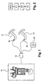
- FIG 1 Diagrammatically shown in figure 1 a motor vehicle which comprises a motor 10, an accelerator pedal 12, a brake pedal 14, and an electronic computing unit 16, for controlling the torque C of the motor 10.
- the engine 10 is here an internal combustion engine, but the invention is applicable to other types of engine such as an electric motor, or to a hybrid powertrain.
- the operating torque C of the engine 10 is controlled according to the degree of depression of the accelerator pedal 12, via the calculation unit 16.
- the vehicle comprises a transmission system 18 a signal S1 representative of the degree of depression of the accelerator pedal 12 to the calculation unit 16.
- the calculation unit 16 controls the torque C of the engine 10 as a function of the acceleration signal S1.
- the transmission system is here an angular sensor 18 which is mounted on the mounting axis (not shown) of the accelerator pedal 12.
- the sensor 18 detects the degree of depression of the accelerator pedal 12.
- the brake pedal 14 comprises a pedal depression sensor 14 which emits a signal S 2 representative of the degree of depression of the brake pedal 14, or "braking signal", intended for the computing unit 16 .
- the senor 20 is a binary type sensor or "all or nothing" that emits a signal representative of the depression of the brake pedal 14 does not contain the information on the degree of depression.
- the vehicle also comprises various sensors 22 which are capable of communicating, to the computing unit 16, signals respectively representative of the torque C of the engine 10, and the speed V of the vehicle
- the computing unit 16 is able to implement a method of detecting a failure of the acceleration signal S1.
- the calculation unit 16 tests the main conditions of stability CS of the depression of the accelerator pedal 12, and the secondary conditions of rolling CR which are representative of the rolling situation. instantaneous vehicle.
- the test of the main stability conditions CS is intended to verify that the acceleration signal S1 indicates a degree of stable depression of the accelerator pedal 12.
- the main stability conditions CS are given without limitation.
- a first stability condition CS1 is that the acceleration pedal 12 is depressed beyond a threshold of minimum depression ⁇ threshold . It is indeed necessary for the accelerator pedal 12 to be depressed to carry out an analysis of the driving stability.
- a second stability condition CS2 is that the absolute value of the variation in time of the depression degree of the accelerator pedal 12 is less than a stability threshold ⁇ threshold / ⁇ t. If the test is positive, the degree of depression of the pedal is considered as generally stable.
- a third stability condition CS3 is that the operating torque C of the motor 10 must be greater than a value, called the floor torque Cp, in order to corroborate the depression test of the accelerator pedal 12.
- the purpose of the test of the secondary conditions of rolling CR is to determine whether the vehicle is running under conditions appropriate to the implementation of the method, that is to say conditions in which the method is not capable of detecting a "False" failure of the acceleration signal.
- a "False" failure of the acceleration signal is an indicative and non-exhaustive list of CR conditions that can be tested.
- the first driving condition CR1 is that the vehicle is traveling at a speed V greater than a floor speed Vp.
- the second CR2 driving condition is that the brake pedal 14 should not be depressed.
- the purpose of this test is to prevent the detection method from concluding that the acceleration signal S1 fails when the braking signal S2 is itself corrupted, ie when the braking signal S2 is " locked "on a depression value of the brake pedal 14 regardless of the actual depression of the brake pedal 14.
- the third rolling condition CR3 is that no other method using and / or generating braking and / or acceleration signals is being implemented. Another method is for example a method for stabilizing the vehicle when traveling on a partially slippery road, also called "ASR".
- another CR rolling condition to be verified is that the signal is not electrically failing, for example that the signal does not have an intensity greater than an upper limit.
- the secondary CR rolling conditions that are given here can be freely combined by those skilled in the art depending on the vehicle on which the method is intended to operate, and in particular according to the conditions likely to cause the detection of a "false" failure.
- a counter T1 initialized to zero, is incremented and the tests are repeated.
- the preliminary step E1 ends, and the first phase P1 of the failure test step E2 is triggered.
- the first phase of simultaneity P1 is intended to detect a simultaneous depression of the accelerator pedal 12 and the brake pedal 14. During this phase P1, it is also verified that the conditions CS stability of the accelerator pedal 12 are always positive.
- the sensor 20 associated with the brake pedal 14 is of the binary type, it simply tests the depression of the brake pedal as a function of the binary signal S2.
- the brake pedal 14 comprises two similar sensors 20 which emit two parallel signals S2 and S2. It is thus possible to perform two simultaneous tests of the two braking signals in order to make the braking test more robust.
- the first phase P1 terminates, and then the second diagnostic phase P2 is triggered.
- the acceleration signal S1 is faulty.
- the combination of the conditions CS, CR and Em tested during the stability step E1 and the first simultaneity phase P1 is indeed an index of the failure of the acceleration signal S1.
- the calculation unit 16 thus emits a signal Sd1 intended to implement the degraded operating mode of the engine 10.
- the signal Sd1 corresponds to a positive test result of all the conditions CS, CR and Em cumulatively.
- the degraded mode is triggered reversibly.
- the main conditions CS of stability of the accelerator pedal 12 are still tested in order to verify that the conditions CS are still fulfilled.
- one of the stability conditions CS is no longer fulfilled, considers that the acceleration signal S1 has been judged to have erroneously failed, and the process is fully reset.
- a counter T3 initialized to zero, is incremented.
- V3 a predetermined value
- the computing unit 16 comprises several processors which make it possible to carry out several tests simultaneously during each step E1 and E2.
- a processor is for example dedicated to testing the main conditions of stability CS.
- the computing unit 16 is made in whole or in part in the form of electronic circuits implementing all or part of the functions described above.
Landscapes
- Engineering & Computer Science (AREA)
- Chemical & Material Sciences (AREA)
- Combustion & Propulsion (AREA)
- Mechanical Engineering (AREA)
- Transportation (AREA)
- General Engineering & Computer Science (AREA)
- Electric Propulsion And Braking For Vehicles (AREA)
- Auxiliary Drives, Propulsion Controls, And Safety Devices (AREA)
- Control Of Throttle Valves Provided In The Intake System Or In The Exhaust System (AREA)
- Control Of Electric Motors In General (AREA)
- Control Of Motors That Do Not Use Commutators (AREA)
Claims (9)
- Verfahren zum Erfassen der Störung eines Systems (18) zum Senden eines Signals, das für den Niederdrückgrad eines Gaspedals (12) eines Kraftfahrzeugs repräsentativ ist, von dem Typ, der einen Testschritt der Störung (E2) aufweist,
dadurch gekennzeichnet, dass es einen vorhergehenden Testschritt (E1) der Beständigkeit des Niederdrückens des Gaspedals (12) aufweist, um die Störungserfassungsfehler zu vermeiden, während dem getestet wird, ob die Veränderung bezüglich der Niederdrückzeit des Gaspedals (12) im Wesentlichen gleich Null ist. - Verfahren nach dem vorhergehenden Anspruch, dadurch gekennzeichnet, dass während des vorhergehenden Schritts (E1) getestet wird, ob das Gaspedal (12) über eine Mindestniederdrückschwelle hinaus niedergedrückt ist.
- Verfahren nach einem der vorhergehenden Ansprüche, dadurch gekennzeichnet, dass während des vorhergehenden Schritts (E1) getestet wird, ob das Drehmoment (C) des Motors (10) höher ist als ein Schwelldrehmoment (Np).
- Verfahren nach einem der Ansprüche 1 bis 3, dadurch gekennzeichnet, dass während des vorhergehenden Schritts (E1) sekundäre Fahrsituationsbedingungen (CR) getestet werden, bei denen das Verfahren einen unechte Störung feststellen kann, und insbesondere, dass das Bremspedal (14) nicht als niedergedrückt angezeigt wird.
- Verfahren nach einem der Ansprüche 1 bis 4, dadurch gekennzeichnet, dass, wenn das Ergebnis der während des vorhergehenden Beständigkeits-Schritts (E1) durchgeführten Tests während einer vorbestimmten Dauer (V1) positiv bleibt, der Testschritt der Störung ausgelöst wird (E2).
- Verfahren nach dem vorhergehenden Anspruch, von dem Typ, bei dem der Testschritt der Störung (E2) nacheinander aufweist:- eine Testphase (P1) der Gleichzeitigkeit des Niederdrückens des Gaspedals (12) und des Bremspedals (14); dann- eine Diagnosephase (P2) der Störung, während der ein Signal (Sd1) gesendet wird, das für die Störung des Sendesystems repräsentativ ist, und die ausgelöst wird, wenn der Gleichzeitigkeitstest der vorhergehenden Phase (P1) während einer bestimmten Dauer (V2) positiv bleibt,dadurch gekennzeichnet, dass in der Testphase der Gleichzeitigkeit (P1) geprüft wird, ob das Niederdrücken des Gaspedals beständig ist und ob das Bremspedal (14) niedergedrückt ist.
- Verfahren nach dem vorhergehenden Anspruch, dadurch gekennzeichnet, dass die Diagnosephase (P2) einen ersten Testvorgang aufweist, während dem geprüft wird, ob das Niederdrücken des Gaspedals beständig ist.
- Verfahren nach einem der vorhergehenden Ansprüche, dadurch gekennzeichnet, dass, wenn das Niederdrücken des Pedals als nicht mehr beständig getestet wird, das Sendesystem (18) nicht als gestört angesehen und das Verfahren neu initialisiert wird.
- Verfahren nach dem vorhergehenden Anspruch, dadurch gekennzeichnet, dass während der Diagnosephase (P2), wenn der erste Testvorgang während einer vorbestimmten Dauer (V3) positiv ist, ein zweiter Vorgang ausgelöst wird, während dem ein Signal (Sd2) gesendet wird, das für eine dauerhafte Störung des Sendesystems repräsentativ ist.
Applications Claiming Priority (2)
| Application Number | Priority Date | Filing Date | Title |
|---|---|---|---|
| FR0310306A FR2859143B1 (fr) | 2003-08-29 | 2003-08-29 | Procede de detection de la defaillance d'un signal representatif de l'enfoncement d'une pedale d'acceleration de vehicule automobile |
| PCT/FR2004/002170 WO2005024212A1 (fr) | 2003-08-29 | 2004-08-20 | Procede de detection de la defaillance d’un signal representatif de l’enfoncement d’une pedale d’acceleration de vehicule automobile |
Publications (2)
| Publication Number | Publication Date |
|---|---|
| EP1660765A1 EP1660765A1 (de) | 2006-05-31 |
| EP1660765B1 true EP1660765B1 (de) | 2009-10-28 |
Family
ID=34130663
Family Applications (1)
| Application Number | Title | Priority Date | Filing Date |
|---|---|---|---|
| EP04786335A Expired - Lifetime EP1660765B1 (de) | 2003-08-29 | 2004-08-20 | Signalfehlererfassungsverfahren, wobei das signal das niederdrücken eines kraftfahrzeuggaspedals repräsentiert |
Country Status (6)
| Country | Link |
|---|---|
| EP (1) | EP1660765B1 (de) |
| JP (1) | JP4609948B2 (de) |
| AT (1) | ATE447101T1 (de) |
| DE (1) | DE602004023859D1 (de) |
| FR (1) | FR2859143B1 (de) |
| WO (1) | WO2005024212A1 (de) |
Families Citing this family (5)
| Publication number | Priority date | Publication date | Assignee | Title |
|---|---|---|---|---|
| JP5282760B2 (ja) * | 2010-04-13 | 2013-09-04 | 日産自動車株式会社 | 内燃機関の出力制御装置 |
| JP5912673B2 (ja) * | 2012-03-02 | 2016-04-27 | 株式会社ケーヒン | 電子制御スロットル装置 |
| CN112158149B (zh) * | 2020-08-26 | 2022-03-01 | 东风汽车集团有限公司 | 加速踏板卡滞识别方法及加速踏板卡滞识别系统 |
| CN112977059B (zh) * | 2021-02-26 | 2022-09-27 | 三一汽车制造有限公司 | 踏板的失效处理方法、装置、车辆、可读存储介质 |
| CN116678606A (zh) * | 2023-07-17 | 2023-09-01 | 浙江吉利控股集团有限公司 | 油门踏板失效检测方法、装置、设备及存储介质 |
Family Cites Families (6)
| Publication number | Priority date | Publication date | Assignee | Title |
|---|---|---|---|---|
| JPS618442A (ja) * | 1984-06-22 | 1986-01-16 | Nissan Motor Co Ltd | 車両用内燃機関のアクセル制御装置における異常診断装置 |
| DE68926459T2 (de) * | 1989-09-21 | 1996-09-12 | Bosch Gmbh Robert | Überwachungssystem für ein fahrpedal-stellungssignal |
| JPH04203244A (ja) * | 1990-11-29 | 1992-07-23 | Mitsubishi Motors Corp | 加速制御部付ドライブバイワイヤ式車両 |
| DE4118375A1 (de) * | 1991-06-05 | 1992-12-10 | Vdo Schindling | Sicherheitsschaltung fuer eine einrichtung zum steuern der leistung einer brennkraftmaschine |
| DE4126025A1 (de) * | 1991-08-06 | 1993-02-11 | Bosch Gmbh Robert | System zur steuerung bzw. regelung einer brennkraftmaschine in einem kraftfahrzeug |
| JP2002195076A (ja) * | 2000-12-27 | 2002-07-10 | Daihatsu Motor Co Ltd | 内燃機関の制御方法 |
-
2003
- 2003-08-29 FR FR0310306A patent/FR2859143B1/fr not_active Expired - Fee Related
-
2004
- 2004-08-20 WO PCT/FR2004/002170 patent/WO2005024212A1/fr not_active Ceased
- 2004-08-20 EP EP04786335A patent/EP1660765B1/de not_active Expired - Lifetime
- 2004-08-20 JP JP2006524390A patent/JP4609948B2/ja not_active Expired - Fee Related
- 2004-08-20 AT AT04786335T patent/ATE447101T1/de not_active IP Right Cessation
- 2004-08-20 DE DE602004023859T patent/DE602004023859D1/de not_active Expired - Lifetime
Also Published As
| Publication number | Publication date |
|---|---|
| WO2005024212A1 (fr) | 2005-03-17 |
| FR2859143A1 (fr) | 2005-03-04 |
| FR2859143B1 (fr) | 2006-02-24 |
| EP1660765A1 (de) | 2006-05-31 |
| JP2007504034A (ja) | 2007-03-01 |
| DE602004023859D1 (de) | 2009-12-10 |
| JP4609948B2 (ja) | 2011-01-12 |
| ATE447101T1 (de) | 2009-11-15 |
Similar Documents
| Publication | Publication Date | Title |
|---|---|---|
| JP6122068B2 (ja) | 車速検出装置の故障判定装置 | |
| WO2010015765A2 (fr) | Procede et systeme de diagnostic de l'etat de fonctionnement d'un systeme de demarrage assiste d'un vehicule automobile | |
| FR2990916A1 (fr) | Procede de detection d'une acceleration intempestive d'un vehicule automobile | |
| FR2697330A1 (fr) | Procédé et dispositif pour la détection d'une grandeur variable dans des véhicules, concernant notamment une pompe d'injection d'un moteur Diesel. | |
| CA3135956A1 (fr) | Systeme de surveillance de la sante d'un helicoptere | |
| EP3661827B1 (de) | Verfahren zur erzeugung eines regelsollwerts für ein antriebselement eines kraftfahrzeugs | |
| FR2859143A1 (fr) | Procede de detection de la defaillance d'un signal representatif de l'enfoncement d'une pedale d'acceleration de vehicule automobile | |
| WO2014202858A1 (fr) | Systeme et procede de surveillance du couple fourni par le moteur d'un vehicule automobile electrique ou hybride | |
| FR2763099A1 (fr) | Procede et dispositif de commande d'un groupe moteur d'un vehicule automobile | |
| EP2307253B1 (de) | Vorrichtung zur bestimmung der querbeschleunigung eines motorfahrzeugs und entsprechendes verfahren | |
| FR2842620A1 (fr) | Procede et systeme destines a realiser une selection entre deux signaux de sortie de capteurs dans un systeme de papillon des gaz electronique | |
| FR2875447A1 (fr) | Dispositif et procede d'exploitation du signal d'un capteur representant la position de la pedale d'accelerateur d'un vehicule automobile | |
| EP0924443B1 (de) | Verfahren zur Erkennung der Kupplungstellung eines Kraftfahrzeugmotors | |
| EP3072019B1 (de) | Kritisches system und zugehöriges überwachungsverfahren | |
| FR2824908A1 (fr) | Procede et dispositif de surveillance de la saisie de valeurs de mesure | |
| FR2966413A1 (fr) | Procede de controle du redemarrage d'un moteur de vehicule et vehicule adapte pour la mise en œuvre de ce procede | |
| WO2023117857A1 (fr) | Dispositif et procédé d'évaluation d'un système d'aide à la conduite pour véhicule automobile, le système d'aide à la conduite mettant en œuvre un réseau neuronal artificiel | |
| JP2022025259A (ja) | 車両 | |
| US20220135045A1 (en) | Road surface type estimation method, road surface type estimation device and vehicle control system | |
| WO2023083703A1 (fr) | Procédé et dispositif de contrôle et commande d'un moteur de véhicule | |
| FR3078668A1 (fr) | Procede de detection d'anomalie dans la perception par un vehicule automobile de son environnement | |
| EP1818741A1 (de) | Elektronische Schnittstelle für einen Fußschalter eines Kraftfahrzeugs | |
| EP2152563B1 (de) | Vorrichtung zur steuerung von parameterwerten durch zuverlässigkeitsanalyse zugehöriger rechner | |
| FR3146447A1 (fr) | Module électronique d’aide à la conduite d’un véhicule automobile | |
| FR3161773A1 (fr) | Sécurisation de l’affichage de témoins sur un écran d’une interface homme-machine d’un véhicule automobile |
Legal Events
| Date | Code | Title | Description |
|---|---|---|---|
| PUAI | Public reference made under article 153(3) epc to a published international application that has entered the european phase |
Free format text: ORIGINAL CODE: 0009012 |
|
| 17P | Request for examination filed |
Effective date: 20060329 |
|
| AK | Designated contracting states |
Kind code of ref document: A1 Designated state(s): AT BE BG CH CY CZ DE DK EE ES FI FR GB GR HU IE IT LI LU MC NL PL PT RO SE SI SK TR |
|
| 17Q | First examination report despatched |
Effective date: 20060719 |
|
| DAX | Request for extension of the european patent (deleted) | ||
| RIN1 | Information on inventor provided before grant (corrected) |
Inventor name: FRAWEEL, OLIVIER Inventor name: MARTINEZ, ALEXANDRE Inventor name: BIEMONT, ANNE |
|
| GRAP | Despatch of communication of intention to grant a patent |
Free format text: ORIGINAL CODE: EPIDOSNIGR1 |
|
| GRAS | Grant fee paid |
Free format text: ORIGINAL CODE: EPIDOSNIGR3 |
|
| GRAA | (expected) grant |
Free format text: ORIGINAL CODE: 0009210 |
|
| AK | Designated contracting states |
Kind code of ref document: B1 Designated state(s): AT BE BG CH CY CZ DE DK EE ES FI FR GB GR HU IE IT LI LU MC NL PL PT RO SE SI SK TR |
|
| REG | Reference to a national code |
Ref country code: GB Ref legal event code: FG4D Free format text: NOT ENGLISH |
|
| REG | Reference to a national code |
Ref country code: CH Ref legal event code: EP |
|
| REG | Reference to a national code |
Ref country code: IE Ref legal event code: FG4D |
|
| REF | Corresponds to: |
Ref document number: 602004023859 Country of ref document: DE Date of ref document: 20091210 Kind code of ref document: P |
|
| NLV1 | Nl: lapsed or annulled due to failure to fulfill the requirements of art. 29p and 29m of the patents act | ||
| PG25 | Lapsed in a contracting state [announced via postgrant information from national office to epo] |
Ref country code: SE Free format text: LAPSE BECAUSE OF FAILURE TO SUBMIT A TRANSLATION OF THE DESCRIPTION OR TO PAY THE FEE WITHIN THE PRESCRIBED TIME-LIMIT Effective date: 20091028 Ref country code: FI Free format text: LAPSE BECAUSE OF FAILURE TO SUBMIT A TRANSLATION OF THE DESCRIPTION OR TO PAY THE FEE WITHIN THE PRESCRIBED TIME-LIMIT Effective date: 20091028 Ref country code: PT Free format text: LAPSE BECAUSE OF FAILURE TO SUBMIT A TRANSLATION OF THE DESCRIPTION OR TO PAY THE FEE WITHIN THE PRESCRIBED TIME-LIMIT Effective date: 20100301 Ref country code: ES Free format text: LAPSE BECAUSE OF FAILURE TO SUBMIT A TRANSLATION OF THE DESCRIPTION OR TO PAY THE FEE WITHIN THE PRESCRIBED TIME-LIMIT Effective date: 20100208 |
|
| REG | Reference to a national code |
Ref country code: IE Ref legal event code: FD4D |
|
| PG25 | Lapsed in a contracting state [announced via postgrant information from national office to epo] |
Ref country code: PL Free format text: LAPSE BECAUSE OF FAILURE TO SUBMIT A TRANSLATION OF THE DESCRIPTION OR TO PAY THE FEE WITHIN THE PRESCRIBED TIME-LIMIT Effective date: 20091028 Ref country code: SI Free format text: LAPSE BECAUSE OF FAILURE TO SUBMIT A TRANSLATION OF THE DESCRIPTION OR TO PAY THE FEE WITHIN THE PRESCRIBED TIME-LIMIT Effective date: 20091028 Ref country code: CY Free format text: LAPSE BECAUSE OF FAILURE TO SUBMIT A TRANSLATION OF THE DESCRIPTION OR TO PAY THE FEE WITHIN THE PRESCRIBED TIME-LIMIT Effective date: 20091028 |
|
| PG25 | Lapsed in a contracting state [announced via postgrant information from national office to epo] |
Ref country code: AT Free format text: LAPSE BECAUSE OF FAILURE TO SUBMIT A TRANSLATION OF THE DESCRIPTION OR TO PAY THE FEE WITHIN THE PRESCRIBED TIME-LIMIT Effective date: 20091028 |
|
| PG25 | Lapsed in a contracting state [announced via postgrant information from national office to epo] |
Ref country code: BG Free format text: LAPSE BECAUSE OF FAILURE TO SUBMIT A TRANSLATION OF THE DESCRIPTION OR TO PAY THE FEE WITHIN THE PRESCRIBED TIME-LIMIT Effective date: 20100128 Ref country code: RO Free format text: LAPSE BECAUSE OF FAILURE TO SUBMIT A TRANSLATION OF THE DESCRIPTION OR TO PAY THE FEE WITHIN THE PRESCRIBED TIME-LIMIT Effective date: 20091028 Ref country code: DK Free format text: LAPSE BECAUSE OF FAILURE TO SUBMIT A TRANSLATION OF THE DESCRIPTION OR TO PAY THE FEE WITHIN THE PRESCRIBED TIME-LIMIT Effective date: 20091028 Ref country code: EE Free format text: LAPSE BECAUSE OF FAILURE TO SUBMIT A TRANSLATION OF THE DESCRIPTION OR TO PAY THE FEE WITHIN THE PRESCRIBED TIME-LIMIT Effective date: 20091028 Ref country code: IE Free format text: LAPSE BECAUSE OF FAILURE TO SUBMIT A TRANSLATION OF THE DESCRIPTION OR TO PAY THE FEE WITHIN THE PRESCRIBED TIME-LIMIT Effective date: 20091028 |
|
| PG25 | Lapsed in a contracting state [announced via postgrant information from national office to epo] |
Ref country code: CZ Free format text: LAPSE BECAUSE OF FAILURE TO SUBMIT A TRANSLATION OF THE DESCRIPTION OR TO PAY THE FEE WITHIN THE PRESCRIBED TIME-LIMIT Effective date: 20091028 Ref country code: SK Free format text: LAPSE BECAUSE OF FAILURE TO SUBMIT A TRANSLATION OF THE DESCRIPTION OR TO PAY THE FEE WITHIN THE PRESCRIBED TIME-LIMIT Effective date: 20091028 |
|
| PLBE | No opposition filed within time limit |
Free format text: ORIGINAL CODE: 0009261 |
|
| STAA | Information on the status of an ep patent application or granted ep patent |
Free format text: STATUS: NO OPPOSITION FILED WITHIN TIME LIMIT |
|
| 26N | No opposition filed |
Effective date: 20100729 |
|
| PG25 | Lapsed in a contracting state [announced via postgrant information from national office to epo] |
Ref country code: GR Free format text: LAPSE BECAUSE OF FAILURE TO SUBMIT A TRANSLATION OF THE DESCRIPTION OR TO PAY THE FEE WITHIN THE PRESCRIBED TIME-LIMIT Effective date: 20100129 |
|
| BERE | Be: lapsed |
Owner name: RENAULT S.A.S. Effective date: 20100831 |
|
| PG25 | Lapsed in a contracting state [announced via postgrant information from national office to epo] |
Ref country code: MC Free format text: LAPSE BECAUSE OF NON-PAYMENT OF DUE FEES Effective date: 20100831 |
|
| REG | Reference to a national code |
Ref country code: CH Ref legal event code: PL |
|
| PG25 | Lapsed in a contracting state [announced via postgrant information from national office to epo] |
Ref country code: LI Free format text: LAPSE BECAUSE OF NON-PAYMENT OF DUE FEES Effective date: 20100831 Ref country code: CH Free format text: LAPSE BECAUSE OF NON-PAYMENT OF DUE FEES Effective date: 20100831 |
|
| PG25 | Lapsed in a contracting state [announced via postgrant information from national office to epo] |
Ref country code: IT Free format text: LAPSE BECAUSE OF NON-PAYMENT OF DUE FEES Effective date: 20100820 |
|
| PG25 | Lapsed in a contracting state [announced via postgrant information from national office to epo] |
Ref country code: BE Free format text: LAPSE BECAUSE OF NON-PAYMENT OF DUE FEES Effective date: 20100831 |
|
| PG25 | Lapsed in a contracting state [announced via postgrant information from national office to epo] |
Ref country code: NL Free format text: LAPSE BECAUSE OF FAILURE TO SUBMIT A TRANSLATION OF THE DESCRIPTION OR TO PAY THE FEE WITHIN THE PRESCRIBED TIME-LIMIT Effective date: 20091028 Ref country code: LU Free format text: LAPSE BECAUSE OF NON-PAYMENT OF DUE FEES Effective date: 20100820 Ref country code: HU Free format text: LAPSE BECAUSE OF FAILURE TO SUBMIT A TRANSLATION OF THE DESCRIPTION OR TO PAY THE FEE WITHIN THE PRESCRIBED TIME-LIMIT Effective date: 20100429 |
|
| PG25 | Lapsed in a contracting state [announced via postgrant information from national office to epo] |
Ref country code: TR Free format text: LAPSE BECAUSE OF FAILURE TO SUBMIT A TRANSLATION OF THE DESCRIPTION OR TO PAY THE FEE WITHIN THE PRESCRIBED TIME-LIMIT Effective date: 20091028 |
|
| REG | Reference to a national code |
Ref country code: FR Ref legal event code: PLFP Year of fee payment: 12 |
|
| REG | Reference to a national code |
Ref country code: FR Ref legal event code: PLFP Year of fee payment: 13 |
|
| REG | Reference to a national code |
Ref country code: FR Ref legal event code: PLFP Year of fee payment: 14 |
|
| REG | Reference to a national code |
Ref country code: FR Ref legal event code: PLFP Year of fee payment: 15 |
|
| PGFP | Annual fee paid to national office [announced via postgrant information from national office to epo] |
Ref country code: FR Payment date: 20210819 Year of fee payment: 18 |
|
| PGFP | Annual fee paid to national office [announced via postgrant information from national office to epo] |
Ref country code: GB Payment date: 20210820 Year of fee payment: 18 Ref country code: DE Payment date: 20210819 Year of fee payment: 18 |
|
| REG | Reference to a national code |
Ref country code: DE Ref legal event code: R119 Ref document number: 602004023859 Country of ref document: DE |
|
| GBPC | Gb: european patent ceased through non-payment of renewal fee |
Effective date: 20220820 |
|
| PG25 | Lapsed in a contracting state [announced via postgrant information from national office to epo] |
Ref country code: FR Free format text: LAPSE BECAUSE OF NON-PAYMENT OF DUE FEES Effective date: 20220831 Ref country code: DE Free format text: LAPSE BECAUSE OF NON-PAYMENT OF DUE FEES Effective date: 20230301 |
|
| PG25 | Lapsed in a contracting state [announced via postgrant information from national office to epo] |
Ref country code: GB Free format text: LAPSE BECAUSE OF NON-PAYMENT OF DUE FEES Effective date: 20220820 |