EP1659375B1 - Modular encoder, method of producing a modular encoder, and system for measuring angular movement - Google Patents
Modular encoder, method of producing a modular encoder, and system for measuring angular movement Download PDFInfo
- Publication number
- EP1659375B1 EP1659375B1 EP05020188A EP05020188A EP1659375B1 EP 1659375 B1 EP1659375 B1 EP 1659375B1 EP 05020188 A EP05020188 A EP 05020188A EP 05020188 A EP05020188 A EP 05020188A EP 1659375 B1 EP1659375 B1 EP 1659375B1
- Authority
- EP
- European Patent Office
- Prior art keywords
- encoder
- mounting bracket
- encoder housing
- printed circuit
- circuit board
- Prior art date
- Legal status (The legal status is an assumption and is not a legal conclusion. Google has not performed a legal analysis and makes no representation as to the accuracy of the status listed.)
- Expired - Lifetime
Links
Images


Classifications
-
- G—PHYSICS
- G01—MEASURING; TESTING
- G01D—MEASURING NOT SPECIALLY ADAPTED FOR A SPECIFIC VARIABLE; ARRANGEMENTS FOR MEASURING TWO OR MORE VARIABLES NOT COVERED IN A SINGLE OTHER SUBCLASS; TARIFF METERING APPARATUS; MEASURING OR TESTING NOT OTHERWISE PROVIDED FOR
- G01D5/00—Mechanical means for transferring the output of a sensing member; Means for converting the output of a sensing member to another variable where the form or nature of the sensing member does not constrain the means for converting; Transducers not specially adapted for a specific variable
- G01D5/12—Mechanical means for transferring the output of a sensing member; Means for converting the output of a sensing member to another variable where the form or nature of the sensing member does not constrain the means for converting; Transducers not specially adapted for a specific variable using electric or magnetic means
- G01D5/244—Mechanical means for transferring the output of a sensing member; Means for converting the output of a sensing member to another variable where the form or nature of the sensing member does not constrain the means for converting; Transducers not specially adapted for a specific variable using electric or magnetic means influencing characteristics of pulses or pulse trains; generating pulses or pulse trains
- G01D5/24428—Error prevention
- G01D5/24433—Error prevention by mechanical means
-
- G—PHYSICS
- G01—MEASURING; TESTING
- G01D—MEASURING NOT SPECIALLY ADAPTED FOR A SPECIFIC VARIABLE; ARRANGEMENTS FOR MEASURING TWO OR MORE VARIABLES NOT COVERED IN A SINGLE OTHER SUBCLASS; TARIFF METERING APPARATUS; MEASURING OR TESTING NOT OTHERWISE PROVIDED FOR
- G01D11/00—Component parts of measuring arrangements not specially adapted for a specific variable
- G01D11/24—Housings ; Casings for instruments
-
- G—PHYSICS
- G01—MEASURING; TESTING
- G01D—MEASURING NOT SPECIALLY ADAPTED FOR A SPECIFIC VARIABLE; ARRANGEMENTS FOR MEASURING TWO OR MORE VARIABLES NOT COVERED IN A SINGLE OTHER SUBCLASS; TARIFF METERING APPARATUS; MEASURING OR TESTING NOT OTHERWISE PROVIDED FOR
- G01D5/00—Mechanical means for transferring the output of a sensing member; Means for converting the output of a sensing member to another variable where the form or nature of the sensing member does not constrain the means for converting; Transducers not specially adapted for a specific variable
- G01D5/12—Mechanical means for transferring the output of a sensing member; Means for converting the output of a sensing member to another variable where the form or nature of the sensing member does not constrain the means for converting; Transducers not specially adapted for a specific variable using electric or magnetic means
- G01D5/244—Mechanical means for transferring the output of a sensing member; Means for converting the output of a sensing member to another variable where the form or nature of the sensing member does not constrain the means for converting; Transducers not specially adapted for a specific variable using electric or magnetic means influencing characteristics of pulses or pulse trains; generating pulses or pulse trains
Definitions
- the present invention relates to measuring devices. More particularly, the present invention relates to a modular encoder according to claim 1, a method of producing a modular encoder according to claim 7, and a system for measuring angular movement according to claim 14.
- Encoders are used to measure angular or linear motion. A common use of encoders is for computer numeric control (CNC) machines. Encoder housings may be made of metal, e.g., in a bearing encoder, or plastic, e.g., in a modular encoder, and may include printed circuit boards (PCB).
- PCB printed circuit boards
- a metal encoder housing of a bearing encoder may directly electrically couple the PCB to the motor.
- metal encoders may be expensive to produce.
- the plastic encoder housing of a modular encoder may be coated to provide a ground path for an enclosed PCB thereof.
- a coated plastic encoder housing may be subject to failure if the coating becomes abraded due to use and/or the coating may be expensive to produce.
- a plastic encoder housing may additionally or alternatively be provided with an external wire that may be soldered to provide a ground path for the PCB.
- An external soldered wire may be difficult and/or expensive to produce and may also be subject to failure due to bending or stressing of the solder bond.
- US Patent 6 024 596 describes a ground terminal which is rigidly mounted in through holes of a printed board.
- a modular encoder includes an electrically non-conductive encoder housing and a printed circuit mounted in the encoder housing.
- the modular encoder also includes a mounting bracket adapted and arranged to electrically couple to the printed circuit board and a mounting screw adapted to couple the encoder housing to a motor and to electrically couple the mounting bracket to the motor.
- the encoder housing may include a bracket assembly, for example clip posts, adapted to hold the printed circuit board against the mounting bracket.
- the encoder housing may include a non-conductive polymer.
- the mounting bracket may be metallic.
- the mounting bracket may include an external tab adapted to extend outside a circumference of the encoder housing and adapted to couple to a drain wire.
- the mounting bracket may include a tab adapted to couple to the printed circuit board, the tab adapted to resiliently flex in response to the printed circuit board being mounted in the encoder housing.
- a method of producing a modular encoder includes inserting an electrically conductive mounting bracket in an electrically non-conductive encoder housing and arranging a printed circuit board on the encoder housing to electrically couple the printed circuit board to the mounting bracket.
- the method also includes connecting the encoder housing to a motor using an electrically conductive connector, the connector contacting the mounting bracket and the motor.
- the method may further include covering the printed circuit board with a cover.
- the mounting bracket may be inserted in the encoder housing during moulding of the encoder housing.
- the electrically conductive connector may include a metal screw.
- the electrically conductive mounting bracket may be metallic.
- the electrically conductive mounting bracket may include a metal tab adapted to couple to the printed circuit board.
- the electrically conductive mounting bracket may include an external tab adapted to couple to a drain wire.
- a system for measuring angular movement includes a modular encoder including an electrically non-conductive encoder housing, a printed circuit board mounted in the encoder housing, and a mounting bracket electrically coupled to the printed circuit board.
- the system also includes a motor and a mounting screw coupling the modular encoder to the motor and electrically coupling the mounting bracket to the motor.
- the mounting bracket may include an external tab adapted to extend to an exterior of the encoder housing.
- the external tab may be adapted to electrically couple to a drain wire.
- the mounting bracket may include a tab adapted to couple to the printed circuit board.
- the tab may be adapted to resiliently flex in response to the printed circuit board being mounted in the encoder housing.
- a device and method using a stamped and formed metal bracket to electrically couple a PCB to a motor through an encoder is described.
- the metal bracket also referred to herein as a mounting bracket
- the connection to the motor is made through a mounting screw.
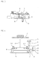
- Figure 1 is a side view of encoder housing 10, PCB 11, mounting bracket 12, and mounting screw 13 according to an exemplary embodiment of the present invention.
- PCB 11 is held in position on encoder housing 10 by clip posts 14.1 and 14.2. There are additional clip posts, or fewer clip posts.
- Clip posts 14.1 and 14.2 are integrated into encoder housing 10, which is composed of any appropriate polymer or other electrically non-conductive material.
- PCB 11 includes circuitry of any appropriate material or manufacture, either on the surface(s) of PCB 11 an/or internal to PCB 11.
- Mounting screw 13 extends below bottom surface 15 of encoder housing 10 to allow attachment to a motor.
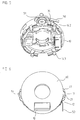
- Figure 2a illustrates from above and to the side encoder housing 10 spatially separated from, and aligned with, PCB 11.
- Mounting bracket 12 having tab 20 is shown positioned in encoder housing 10 so that tab 20 is exposed to PCB 11.
- Head 21 of mounting screw 13 is illustrated contacting washer contact area 22 of mounting bracket 12.
- Figure 2b illustrates from below and to the side encoder housing 10 spatially separated from, and aligned with, PCB 11.
- Mounting screw 13 is shown extending below encoder housing 10.
- PCB contact 23 is shown on a bottom side of PCB 11.
- Figure 3 is a schematic view of electrical path 30 in a side view of an exemplary embodiment of the present invention. Electrical path 30 is shown extending from PCB 11 through mounting bracket 12 positioned in encoder housing 10 to mounting screw 13.
- Figure 4 is an exploded side view of encoder housing 10, PCB 11, mounting bracket 12, and mounting screw 13.
- An exemplary method of manufacturing an encoder includes the steps of inserting mounting bracket 12 in the direction of arrow 40 into a slot of encoder housing 10.
- Mounting bracket 12 may or may not be further positioned within encoder housing 10 by moving mounting bracket 12 in the direction of arrow 41.
- PCB 11 is arranged on encoder housing 10 by moving it in the direction of arrow 42.
- PCB 11 is positioned under clip posts 14.2 and 14.3.
- Mounting screw 13 having head 21 is moved in the direction of arrow 13 to contact washer contact area 22 of mounting bracket 12.
- Mounting screw 13 extends below bottom surface 15 of encoder housing 10 to allow attachment to a motor.
- the manufacturing steps are performed in a different order and/or are eliminated completely in alternative exemplary embodiments of the present invention.
- FIG. 5 illustrates encoder housing 10 with tab 20 of mounting bracket 12 exposed to a top side.
- This exemplary embodiment of mounting bracket 12 includes an external tab 50, which extends out of a slot in encoder housing 10, e.g., the same slot used to position mounting bracket 12 in encoder housing 10.
- External tab 50 is adapted to be used as an attachment point for a drain wire and/or a lug, e.g., by a crimp connection, a soldered connection, a lug connection, a screw connection, etc.
- additional mounting screw 51 which is positioned on a side opposite to the other mounting screw. There may be any of one or more mounting screws in total.
- the tab 20 of the mounting bracket 12 is arranged to flex, e.g., resiliently flex, in response to mounting of the PCB 11 in the encoder housing 10. This flexing contact reliably maintains stable contact between the PCB 11 and the mounting bracket 12 despite vibration to which the encoder is subjected when mounted to a motor and permits relatively high manufacturing tolerances for the encoder housing 10 and the PCB 11.
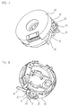
- FIG. 6 is a top view of an exemplary embodiment of the present invention.
- Encoder housing 10 is partially or completely covered by PCB cover 60.
- Mounting screw 13 holds mounting bracket 12 in place by head 21 contacting washer contact area 22.
- Mounting screw 13 attaches the encoder to a motor.
- External tab 50 extends beyond the circumference of encoder housing 10. Opposite to mounting screw 13 is additional mounting screw 51.
- Figure 7 illustrates encoder housing 10 partially or completely covered by PCB cover 60 from above and to the side.
- Mounting screw 13 holds mounting bracket 12 in place by head 21 contacting washer contact area 22.
- Mounting screw 13 attaches the encoder to a motor.
- External tab 50 extends beyond the circumference of encoder housing 10.
- FIG 8 is an enlarged view of an exemplary embodiment of the present invention.
- Mounting bracket 12 is positioned in encoder housing 10.
- Mounting screw 13 holds mounting bracket 12 in place by head 21 contacting washer contact area 22.
- External tab 50 of mounting bracket 12 extends beyond the circumference of encoder housing 10.
- Tab 20 of mounting bracket 12 extends above the top side of encoder housing 10 where it electrically couples to a PCB.
- Figure 9 is a flow chart illustrating a method of an example embodiment of the present invention.
- the method illustrated in Figure 9 begins at start 90 and proceeds to action 91, which indicates to insert an electrically conductive mounting bracket in an encoder housing. From action 91, the method proceeds to action 92, which indicates to arrange a printed circuit board on the encoder housing electrically coupled to the mounting bracket. From action 92, the method proceeds to action 93, which indicates to connect the encoder housing to a motor using an electrically conductive connector. The connector contacts the mounting bracket and the motor. From action 93, the method proceeds to action 94, which indicates to cover the printed circuit board with a cover. From action 94, the method proceeds to end 95.
- the mounting bracket 12 is integrated into an injection moulded encoder housing 10, e.g., prior to injection moulding of the encoder housing 10 so that the encoder housing 10 and mounting bracket 12 is manufactured as a single part.
- the mounting bracket 12 Prior to moulding of the encoder housing 10, the mounting bracket 12 is inserted into the mould. After insertion of the mounting bracket 12 into the mould, the encoder housing 10 is then formed. Since the encoder housing 10 and mounting bracket 12 are integral, the PCB 11 is then mounted to the encoder housing 10 without having to fix the mounting bracket 12 relative to the encoder housing 10 during mounting of the PCB 11 to the encoder housing 10.
Landscapes
- Physics & Mathematics (AREA)
- General Physics & Mathematics (AREA)
- Mounting Of Printed Circuit Boards And The Like (AREA)
- Transmission And Conversion Of Sensor Element Output (AREA)
Applications Claiming Priority (1)
| Application Number | Priority Date | Filing Date | Title |
|---|---|---|---|
| US10/996,253 US7222543B2 (en) | 2004-11-23 | 2004-11-23 | Modular encoder, method of producing a modular encoder, and system for measuring angular movement |
Publications (2)
| Publication Number | Publication Date |
|---|---|
| EP1659375A1 EP1659375A1 (en) | 2006-05-24 |
| EP1659375B1 true EP1659375B1 (en) | 2012-08-01 |
Family
ID=35840377
Family Applications (1)
| Application Number | Title | Priority Date | Filing Date |
|---|---|---|---|
| EP05020188A Expired - Lifetime EP1659375B1 (en) | 2004-11-23 | 2005-09-16 | Modular encoder, method of producing a modular encoder, and system for measuring angular movement |
Country Status (4)
| Country | Link |
|---|---|
| US (1) | US7222543B2 (enExample) |
| EP (1) | EP1659375B1 (enExample) |
| JP (1) | JP5030416B2 (enExample) |
| CN (1) | CN100501335C (enExample) |
Families Citing this family (6)
| Publication number | Priority date | Publication date | Assignee | Title |
|---|---|---|---|---|
| US7438588B2 (en) * | 2006-12-13 | 2008-10-21 | Renco Encoders, Inc. | Encoder and encoder cover with strain relief |
| US9518815B2 (en) * | 2008-08-06 | 2016-12-13 | Haas Automation, Inc. | Rotary position encoder for rotatable shafts |
| JP2017223528A (ja) * | 2016-06-15 | 2017-12-21 | Ntn株式会社 | トルク検出装置 |
| EP3683551B1 (de) * | 2019-01-17 | 2021-03-10 | Dr. Johannes Heidenhain GmbH | Abtasteinheit für eine winkelmesseinrichtung |
| EP3705851A1 (de) | 2019-03-06 | 2020-09-09 | Siemens Aktiengesellschaft | Haltevorrichtung für einen drehgeber |
| CN115752529A (zh) * | 2022-11-15 | 2023-03-07 | 安湘燕 | 旋转编码器及其安装方法 |
Family Cites Families (18)
| Publication number | Priority date | Publication date | Assignee | Title |
|---|---|---|---|---|
| US4654522A (en) * | 1983-09-22 | 1987-03-31 | Cts Corporation | Miniature position encoder with radially non-aligned light emitters and detectors |
| JPS61219832A (ja) | 1985-03-26 | 1986-09-30 | Omron Tateisi Electronics Co | フオトセンサ |
| JPS61188394U (enExample) * | 1985-05-14 | 1986-11-25 | ||
| JPS6219770A (ja) | 1985-07-19 | 1987-01-28 | Fanuc Ltd | パルスエンコ−ダをそなえたモ−タ |
| JPS6236519A (ja) | 1985-08-12 | 1987-02-17 | Fanuc Ltd | 耐雑音形光学式エンコ−ダ |
| JPS62277521A (ja) | 1986-05-27 | 1987-12-02 | Tamagawa Seiki Co Ltd | ロ−タリエンコ−ダ |
| JPH0420816A (ja) | 1990-05-16 | 1992-01-24 | Mitsubishi Electric Corp | 回転角度検出装置 |
| US5057684A (en) * | 1990-08-30 | 1991-10-15 | Robbins & Myers/Electro-Craft, A Wholly Owned Sub. Of Robbins & Myers, Inc. | Unitary aligning and gapping apparatus for modular optical shaft encoder |
| US6024586A (en) * | 1993-11-25 | 2000-02-15 | Kyoshin Kogyo Co., Ltd. | Ground terminal |
| US5708496A (en) * | 1996-03-11 | 1998-01-13 | Renco Encoders, Inc. | Modular optical shaft encoder having a slide gap centering mechanism and method of use |
| JPH09311057A (ja) | 1996-05-24 | 1997-12-02 | Matsushita Electric Ind Co Ltd | ロータリーエンコーダ |
| US6024596A (en) | 1997-02-03 | 2000-02-15 | Yazaki Corporation | Joint structure of flat cable and joint terminals |
| US6205034B1 (en) | 1999-09-24 | 2001-03-20 | Wilson Greatbatch Ltd. | Protection device for protecting an electrical component and method of assembling a battery with a protection device and an electrical component |
| JP2001221661A (ja) | 2000-02-10 | 2001-08-17 | Matsushita Electric Ind Co Ltd | ロータリーエンコーダ |
| DE10115549A1 (de) * | 2001-03-28 | 2002-10-02 | Heidenhain Gmbh Dr Johannes | Winkelmessgerät und dessen Verwendung |
| US6600151B2 (en) * | 2001-09-19 | 2003-07-29 | Lexmark International, Inc. | Optical encoder assembly with non-engageable encoder housing and receiver plate comprising a through hole and window |
| JP2005517909A (ja) * | 2002-02-14 | 2005-06-16 | ファロ テクノロジーズ インコーポレーテッド | 多関節アームを有する可搬式座標測定器 |
| US6733457B2 (en) * | 2002-06-11 | 2004-05-11 | Vermon | Motorized multiplane transducer tip apparatus with transducer locking |
-
2004
- 2004-11-23 US US10/996,253 patent/US7222543B2/en not_active Expired - Lifetime
-
2005
- 2005-09-16 EP EP05020188A patent/EP1659375B1/en not_active Expired - Lifetime
- 2005-11-22 JP JP2005336841A patent/JP5030416B2/ja not_active Expired - Lifetime
- 2005-11-23 CN CNB2005101270051A patent/CN100501335C/zh not_active Expired - Fee Related
Also Published As
| Publication number | Publication date |
|---|---|
| US7222543B2 (en) | 2007-05-29 |
| JP5030416B2 (ja) | 2012-09-19 |
| US20060107760A1 (en) | 2006-05-25 |
| CN100501335C (zh) | 2009-06-17 |
| CN1782673A (zh) | 2006-06-07 |
| EP1659375A1 (en) | 2006-05-24 |
| JP2006145542A (ja) | 2006-06-08 |
Similar Documents
| Publication | Publication Date | Title |
|---|---|---|
| US20070032104A1 (en) | Electrical connector | |
| JP4697163B2 (ja) | 電子装置 | |
| US6755677B2 (en) | Electronic circuit unit having a penetration-type connector housing | |
| EP1986478B1 (en) | Metal wiring plate | |
| EP1659375B1 (en) | Modular encoder, method of producing a modular encoder, and system for measuring angular movement | |
| KR20070093849A (ko) | 접지 도체를 구비한 전기 모터용 인쇄 회로 기판 및 전기모터 | |
| JPH1141682A (ja) | マイク取付装置及び取付方法 | |
| US20070109748A1 (en) | Adjusting device especially for a throttle valve of an internal combustion engine | |
| EP0654184B1 (en) | Connector device and method for manufacturing same | |
| US7437929B2 (en) | Liquid level detector | |
| JP2003045525A (ja) | コネクタ | |
| CN111406140A (zh) | 车门把手 | |
| KR101035471B1 (ko) | 보강용 탭, 보강용 탭을 구비한 커넥터 및 전기 부품과기판의 접속 구조 | |
| JP2000307285A (ja) | 回路基板用中間枠 | |
| KR100546096B1 (ko) | 컨넥터 장치의 전기적 접속구조 | |
| JP5035746B2 (ja) | 回転検出装置 | |
| US6490164B2 (en) | Attachment structure of electronic component to circuit board and clip used in attachment of the electronic component | |
| KR100846938B1 (ko) | 다수의 터미널이 고정된 인쇄회로기판 조립체 | |
| JP5146901B2 (ja) | 回転検出装置 | |
| JP5922325B2 (ja) | 回路基板用電気コネクタ | |
| JP2006236613A (ja) | コネクタ固定構造及び固定方法、並びにコネクタ構造 | |
| JP3246904B2 (ja) | 導電部材 | |
| JP2001221661A (ja) | ロータリーエンコーダ | |
| KR20240058777A (ko) | 차량용 센서 어셈블리 | |
| JPH04133496U (ja) | 電子機器用筐体 |
Legal Events
| Date | Code | Title | Description |
|---|---|---|---|
| PUAI | Public reference made under article 153(3) epc to a published international application that has entered the european phase |
Free format text: ORIGINAL CODE: 0009012 |
|
| AK | Designated contracting states |
Kind code of ref document: A1 Designated state(s): AT BE BG CH CY CZ DE DK EE ES FI FR GB GR HU IE IS IT LI LT LU LV MC NL PL PT RO SE SI SK TR |
|
| AX | Request for extension of the european patent |
Extension state: AL BA HR MK YU |
|
| 17P | Request for examination filed |
Effective date: 20061124 |
|
| 17Q | First examination report despatched |
Effective date: 20061219 |
|
| AKX | Designation fees paid |
Designated state(s): AT BE BG CH CY CZ DE DK EE ES FI FR GB GR HU IE IS IT LI LT LU LV MC NL PL PT RO SE SI SK TR |
|
| REG | Reference to a national code |
Ref country code: DE Ref legal event code: R079 Ref document number: 602005035343 Country of ref document: DE Free format text: PREVIOUS MAIN CLASS: G01D0011240000 Ipc: G01D0005244000 |
|
| GRAP | Despatch of communication of intention to grant a patent |
Free format text: ORIGINAL CODE: EPIDOSNIGR1 |
|
| RIC1 | Information provided on ipc code assigned before grant |
Ipc: G01D 5/244 20060101AFI20120329BHEP Ipc: G01D 11/24 20060101ALI20120329BHEP |
|
| GRAS | Grant fee paid |
Free format text: ORIGINAL CODE: EPIDOSNIGR3 |
|
| GRAA | (expected) grant |
Free format text: ORIGINAL CODE: 0009210 |
|
| AK | Designated contracting states |
Kind code of ref document: B1 Designated state(s): AT BE BG CH CY CZ DE DK EE ES FI FR GB GR HU IE IS IT LI LT LU LV MC NL PL PT RO SE SI SK TR |
|
| REG | Reference to a national code |
Ref country code: GB Ref legal event code: FG4D |
|
| REG | Reference to a national code |
Ref country code: CH Ref legal event code: EP Ref country code: AT Ref legal event code: REF Ref document number: 568912 Country of ref document: AT Kind code of ref document: T Effective date: 20120815 |
|
| REG | Reference to a national code |
Ref country code: IE Ref legal event code: FG4D |
|
| REG | Reference to a national code |
Ref country code: DE Ref legal event code: R096 Ref document number: 602005035343 Country of ref document: DE Effective date: 20121011 |
|
| REG | Reference to a national code |
Ref country code: NL Ref legal event code: VDEP Effective date: 20120801 |
|
| REG | Reference to a national code |
Ref country code: AT Ref legal event code: MK05 Ref document number: 568912 Country of ref document: AT Kind code of ref document: T Effective date: 20120801 |
|
| REG | Reference to a national code |
Ref country code: LT Ref legal event code: MG4D Effective date: 20120801 |
|
| PG25 | Lapsed in a contracting state [announced via postgrant information from national office to epo] |
Ref country code: AT Free format text: LAPSE BECAUSE OF FAILURE TO SUBMIT A TRANSLATION OF THE DESCRIPTION OR TO PAY THE FEE WITHIN THE PRESCRIBED TIME-LIMIT Effective date: 20120801 Ref country code: FI Free format text: LAPSE BECAUSE OF FAILURE TO SUBMIT A TRANSLATION OF THE DESCRIPTION OR TO PAY THE FEE WITHIN THE PRESCRIBED TIME-LIMIT Effective date: 20120801 Ref country code: LT Free format text: LAPSE BECAUSE OF FAILURE TO SUBMIT A TRANSLATION OF THE DESCRIPTION OR TO PAY THE FEE WITHIN THE PRESCRIBED TIME-LIMIT Effective date: 20120801 Ref country code: IS Free format text: LAPSE BECAUSE OF FAILURE TO SUBMIT A TRANSLATION OF THE DESCRIPTION OR TO PAY THE FEE WITHIN THE PRESCRIBED TIME-LIMIT Effective date: 20121201 Ref country code: CY Free format text: LAPSE BECAUSE OF FAILURE TO SUBMIT A TRANSLATION OF THE DESCRIPTION OR TO PAY THE FEE WITHIN THE PRESCRIBED TIME-LIMIT Effective date: 20120801 |
|
| PG25 | Lapsed in a contracting state [announced via postgrant information from national office to epo] |
Ref country code: GR Free format text: LAPSE BECAUSE OF FAILURE TO SUBMIT A TRANSLATION OF THE DESCRIPTION OR TO PAY THE FEE WITHIN THE PRESCRIBED TIME-LIMIT Effective date: 20121102 Ref country code: PL Free format text: LAPSE BECAUSE OF FAILURE TO SUBMIT A TRANSLATION OF THE DESCRIPTION OR TO PAY THE FEE WITHIN THE PRESCRIBED TIME-LIMIT Effective date: 20120801 Ref country code: BE Free format text: LAPSE BECAUSE OF FAILURE TO SUBMIT A TRANSLATION OF THE DESCRIPTION OR TO PAY THE FEE WITHIN THE PRESCRIBED TIME-LIMIT Effective date: 20120801 Ref country code: LV Free format text: LAPSE BECAUSE OF FAILURE TO SUBMIT A TRANSLATION OF THE DESCRIPTION OR TO PAY THE FEE WITHIN THE PRESCRIBED TIME-LIMIT Effective date: 20120801 Ref country code: SE Free format text: LAPSE BECAUSE OF FAILURE TO SUBMIT A TRANSLATION OF THE DESCRIPTION OR TO PAY THE FEE WITHIN THE PRESCRIBED TIME-LIMIT Effective date: 20120801 Ref country code: PT Free format text: LAPSE BECAUSE OF FAILURE TO SUBMIT A TRANSLATION OF THE DESCRIPTION OR TO PAY THE FEE WITHIN THE PRESCRIBED TIME-LIMIT Effective date: 20121203 Ref country code: SI Free format text: LAPSE BECAUSE OF FAILURE TO SUBMIT A TRANSLATION OF THE DESCRIPTION OR TO PAY THE FEE WITHIN THE PRESCRIBED TIME-LIMIT Effective date: 20120801 |
|
| PG25 | Lapsed in a contracting state [announced via postgrant information from national office to epo] |
Ref country code: NL Free format text: LAPSE BECAUSE OF FAILURE TO SUBMIT A TRANSLATION OF THE DESCRIPTION OR TO PAY THE FEE WITHIN THE PRESCRIBED TIME-LIMIT Effective date: 20120801 |
|
| PG25 | Lapsed in a contracting state [announced via postgrant information from national office to epo] |
Ref country code: DK Free format text: LAPSE BECAUSE OF FAILURE TO SUBMIT A TRANSLATION OF THE DESCRIPTION OR TO PAY THE FEE WITHIN THE PRESCRIBED TIME-LIMIT Effective date: 20120801 Ref country code: EE Free format text: LAPSE BECAUSE OF FAILURE TO SUBMIT A TRANSLATION OF THE DESCRIPTION OR TO PAY THE FEE WITHIN THE PRESCRIBED TIME-LIMIT Effective date: 20120801 Ref country code: ES Free format text: LAPSE BECAUSE OF FAILURE TO SUBMIT A TRANSLATION OF THE DESCRIPTION OR TO PAY THE FEE WITHIN THE PRESCRIBED TIME-LIMIT Effective date: 20121112 Ref country code: CZ Free format text: LAPSE BECAUSE OF FAILURE TO SUBMIT A TRANSLATION OF THE DESCRIPTION OR TO PAY THE FEE WITHIN THE PRESCRIBED TIME-LIMIT Effective date: 20120801 Ref country code: RO Free format text: LAPSE BECAUSE OF FAILURE TO SUBMIT A TRANSLATION OF THE DESCRIPTION OR TO PAY THE FEE WITHIN THE PRESCRIBED TIME-LIMIT Effective date: 20120801 Ref country code: MC Free format text: LAPSE BECAUSE OF NON-PAYMENT OF DUE FEES Effective date: 20120930 |
|
| REG | Reference to a national code |
Ref country code: CH Ref legal event code: PL |
|
| PG25 | Lapsed in a contracting state [announced via postgrant information from national office to epo] |
Ref country code: SK Free format text: LAPSE BECAUSE OF FAILURE TO SUBMIT A TRANSLATION OF THE DESCRIPTION OR TO PAY THE FEE WITHIN THE PRESCRIBED TIME-LIMIT Effective date: 20120801 Ref country code: IT Free format text: LAPSE BECAUSE OF FAILURE TO SUBMIT A TRANSLATION OF THE DESCRIPTION OR TO PAY THE FEE WITHIN THE PRESCRIBED TIME-LIMIT Effective date: 20120801 |
|
| PLBE | No opposition filed within time limit |
Free format text: ORIGINAL CODE: 0009261 |
|
| STAA | Information on the status of an ep patent application or granted ep patent |
Free format text: STATUS: NO OPPOSITION FILED WITHIN TIME LIMIT |
|
| REG | Reference to a national code |
Ref country code: IE Ref legal event code: MM4A |
|
| REG | Reference to a national code |
Ref country code: FR Ref legal event code: ST Effective date: 20130531 |
|
| 26N | No opposition filed |
Effective date: 20130503 |
|
| GBPC | Gb: european patent ceased through non-payment of renewal fee |
Effective date: 20121101 |
|
| PG25 | Lapsed in a contracting state [announced via postgrant information from national office to epo] |
Ref country code: IE Free format text: LAPSE BECAUSE OF NON-PAYMENT OF DUE FEES Effective date: 20120916 Ref country code: LI Free format text: LAPSE BECAUSE OF NON-PAYMENT OF DUE FEES Effective date: 20120930 Ref country code: BG Free format text: LAPSE BECAUSE OF FAILURE TO SUBMIT A TRANSLATION OF THE DESCRIPTION OR TO PAY THE FEE WITHIN THE PRESCRIBED TIME-LIMIT Effective date: 20121101 Ref country code: CH Free format text: LAPSE BECAUSE OF NON-PAYMENT OF DUE FEES Effective date: 20120930 |
|
| REG | Reference to a national code |
Ref country code: DE Ref legal event code: R097 Ref document number: 602005035343 Country of ref document: DE Effective date: 20130503 |
|
| PG25 | Lapsed in a contracting state [announced via postgrant information from national office to epo] |
Ref country code: FR Free format text: LAPSE BECAUSE OF NON-PAYMENT OF DUE FEES Effective date: 20121001 |
|
| PG25 | Lapsed in a contracting state [announced via postgrant information from national office to epo] |
Ref country code: GB Free format text: LAPSE BECAUSE OF NON-PAYMENT OF DUE FEES Effective date: 20121101 |
|
| PG25 | Lapsed in a contracting state [announced via postgrant information from national office to epo] |
Ref country code: TR Free format text: LAPSE BECAUSE OF FAILURE TO SUBMIT A TRANSLATION OF THE DESCRIPTION OR TO PAY THE FEE WITHIN THE PRESCRIBED TIME-LIMIT Effective date: 20120801 |
|
| PG25 | Lapsed in a contracting state [announced via postgrant information from national office to epo] |
Ref country code: LU Free format text: LAPSE BECAUSE OF NON-PAYMENT OF DUE FEES Effective date: 20120916 |
|
| PG25 | Lapsed in a contracting state [announced via postgrant information from national office to epo] |
Ref country code: HU Free format text: LAPSE BECAUSE OF FAILURE TO SUBMIT A TRANSLATION OF THE DESCRIPTION OR TO PAY THE FEE WITHIN THE PRESCRIBED TIME-LIMIT Effective date: 20050916 |
|
| PGFP | Annual fee paid to national office [announced via postgrant information from national office to epo] |
Ref country code: DE Payment date: 20230920 Year of fee payment: 19 |
|
| REG | Reference to a national code |
Ref country code: DE Ref legal event code: R119 Ref document number: 602005035343 Country of ref document: DE |
|
| PG25 | Lapsed in a contracting state [announced via postgrant information from national office to epo] |
Ref country code: DE Free format text: LAPSE BECAUSE OF NON-PAYMENT OF DUE FEES Effective date: 20250401 |