EP1658145B1 - Steuerung und system zur abgabe von fluidmaterial - Google Patents
Steuerung und system zur abgabe von fluidmaterial Download PDFInfo
- Publication number
- EP1658145B1 EP1658145B1 EP04782333A EP04782333A EP1658145B1 EP 1658145 B1 EP1658145 B1 EP 1658145B1 EP 04782333 A EP04782333 A EP 04782333A EP 04782333 A EP04782333 A EP 04782333A EP 1658145 B1 EP1658145 B1 EP 1658145B1
- Authority
- EP
- European Patent Office
- Prior art keywords
- flow rate
- pressure
- fluid
- period
- theoretical
- Prior art date
- Legal status (The legal status is an assumption and is not a legal conclusion. Google has not performed a legal analysis and makes no representation as to the accuracy of the status listed.)
- Expired - Fee Related
Links
Images


Classifications
-
- B—PERFORMING OPERATIONS; TRANSPORTING
- B05—SPRAYING OR ATOMISING IN GENERAL; APPLYING FLUENT MATERIALS TO SURFACES, IN GENERAL
- B05B—SPRAYING APPARATUS; ATOMISING APPARATUS; NOZZLES
- B05B12/00—Arrangements for controlling delivery; Arrangements for controlling the spray area
- B05B12/08—Arrangements for controlling delivery; Arrangements for controlling the spray area responsive to condition of liquid or other fluent material to be discharged, of ambient medium or of target ; responsive to condition of spray devices or of supply means, e.g. pipes, pumps or their drive means
- B05B12/085—Arrangements for controlling delivery; Arrangements for controlling the spray area responsive to condition of liquid or other fluent material to be discharged, of ambient medium or of target ; responsive to condition of spray devices or of supply means, e.g. pipes, pumps or their drive means responsive to flow or pressure of liquid or other fluent material to be discharged
-
- B—PERFORMING OPERATIONS; TRANSPORTING
- B05—SPRAYING OR ATOMISING IN GENERAL; APPLYING FLUENT MATERIALS TO SURFACES, IN GENERAL
- B05C—APPARATUS FOR APPLYING FLUENT MATERIALS TO SURFACES, IN GENERAL
- B05C11/00—Component parts, details or accessories not specifically provided for in groups B05C1/00 - B05C9/00
- B05C11/10—Storage, supply or control of liquid or other fluent material; Recovery of excess liquid or other fluent material
- B05C11/1002—Means for controlling supply, i.e. flow or pressure, of liquid or other fluent material to the applying apparatus, e.g. valves
- B05C11/1007—Means for controlling supply, i.e. flow or pressure, of liquid or other fluent material to the applying apparatus, e.g. valves responsive to condition of liquid or other fluent material
- B05C11/1013—Means for controlling supply, i.e. flow or pressure, of liquid or other fluent material to the applying apparatus, e.g. valves responsive to condition of liquid or other fluent material responsive to flow or pressure of liquid or other fluent material
Definitions
- Dispensing systems are well known in industrial applications for dispensing viscous materials such as sealants, adhesives, coatings, and the like onto a workpiece. These applications may be to seal the workpiece, to adhere the workpiece to another structure, or to coat the workpiece. Changes in the viscosity of the viscous material being dispensed, wear of components of the dispensing system, and operating abnormalities such as air bubbles within the dispensing system are common in such dispensing systems. The changes in operational characteristics of the viscous material and the dispensing system continuously impact an actual dispensing rate of the viscous material. As a result, the prior art has attempted to provide methods to compensate the actual dispensing rate to account for such changes.
- Dispensing systems are well known in industrial applications for dispensing viscous materials such as sealants, adhesives, coatings, and the like onto a workpiece. These applications may be to seal the workpiece, to adhere the workpiece to another structure, or to coat the workpiece. Changes in the viscosity of the viscous material being dispensed, wear of components of the dispensing system, and operating abnormalities such as air bubbles within the dispensing system are common in such dispensing systems. The changes in operational characteristics of the viscous material and the dispensing system continuously impact an actual dispensing rate of the viscous material. As a result, the prior art has attempted to provide methods to compensate the actual dispensing rate to account for such changes.
- Price discloses a method of controlling a dispensing system to dispense a viscous material onto a workpiece. Specifically Price discloses a method of compensating an actual dispensing rate of the viscous material to maintain the actual dispensing rate within a minimum deviation of a target dispensing rate. However, Price discloses a method for compensating the actual dispensing rate only once per job cycle. This periodic compensation frequency does not account for the dynamic characteristics of the viscous materials during each job cycle and the operating abnormalities that maybe encountered during each job cycle.
- Tofte et al. discloses a method of controlling a dispensing system to dispense chemicals onto a field. Specifically, Tofte et al. discloses a method of compensating an actual dispensing rate of the chemicals to account for wear of components of the dispensing system thereby maintaining the actual dispensing rate within a minimum deviation of a target dispensing rate.
- the method includes dispensing the chemicals onto the field during a first time period and measuring a pressure of the chemicals after each of a plurality of time increments within the first time period as the chemicals are dispensed.
- the method continues by determining the theoretical volume of the chemicals dispensed during the first time period based on the pressure measurements during the first time period and an initial compensation factor. An actual volume of the chemicals dispensed during the first time period is simultaneously measured. The theoretical volume dispensed during the first time period is then compared to the actual volume dispensed during the first time period and a first new value for the compensation factor is derived therefrom.
- the method of Tofte et al. continues by dispensing the chemicals onto the field during a second time period and measuring a pressure of the chemicals after each of a plurality of time increments within the second time period.
- the method continues, as before, by determining a theoretical volume of the chemicals dispensed during the second time period based on the pressure measurements during the second time period and the first new value for the compensation factor.
- An actual volume of the chemicals dispensed during the second time period is simultaneously measured.
- the controller compares the theoretical and actual volumes of the chemicals dispensed during the second time period and derives a second new value for the compensation factor therefrom.
- Tofte et al. discloses that the second time period is periodically spaced from the first time period. Tofte et al.
- Tofte et al. discloses using the compensation factor to compensate the actual dispensing rate to maintain the actual dispensing rate within the minimum deviation from - the target dispensing rate.
- the compensation factor is recalculated in each time period, e.g., the first and second new values for the compensation factor are determined, by comparing the actual and theoretical volumes of the chemicals dispensed during each of the time periods.
- the time periods are periodically spaced from one another.
- the present invention provides a method for controlling a fluid delivery system that includes a controllable pressure regulating device, a pressure sensor, a flow meter, and a controller.
- Initial values of a compensation factor and a cracking pressure are established, and a pressure of the fluid at each of a plurality of time increments occurring during periods while the fluid is dispensed is measured.
- a volume of the fluid dispensed during a first period, an average pressure at the time internals during the first period, and an actual average flow rate during the first period are determined.
- the average pressure value, the average flow rate value, a new compensation factor and a new cracking pressure are used to determine a theoretical flow rate for controlling the pressure regulating device and producing a pressure corresponding to the target flow rate.
- the new compensation factor and new cracking pressure are both calculated values.
- the theoretical flow rate is calculated using a least square technique.
- the method is characterized by at least a portion of the second time period occurring consecutively with the first time period to compensate for changes in operational characteristics of the viscous material and the dispensing system thereby maintaining the actual dispensing rate within the minimum deviation of the target dispensing rate.
- the dispensing system can more quickly compensate the actual dispensing rate in the second time period for the changes in operational characteristics of the viscous material and the dispensing system during the first time period.
- changes include changes in viscosity, air bubbles in the dispensing system, plugged nozzles, and the like.
- these changes can have an immediate impact on the actual dispensing rate of the viscous material. For instance, a change in viscosity requires immediate compensation to ensure that the viscous material is being dispensed within the minimum deviation of the target dispensing rate.
- the dispensing system and method of controlling the dispensing system of the present invention accomplish this by continually determining a new value for the compensation factor, i.e., recalculating the compensation factor.
- the method of the present invention provides a better quality seal in the case of the viscous material being a sealant, and saves costs by reducing excessive dispensing.
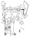
- a dispensing system for dispensing a viscous material 10 onto a workpiece 12 at an actual dispensing rate that is within a minimum deviation of a target dispensing rate is generally shown at 14.
- the dispensing system 14 of the present invention is preferably used in industrial applications that require accurate dispensing of the viscous material 10 onto the workpiece 12. Such applications may include, but are not limited to, dispensing paint onto the workpiece 12, dispensing sealant onto the workpiece 12 to seal the workpiece 12 from moisture, or dispensing an adhesive onto the workpiece 12 to affix the workpiece 12 to a separate structure.
- a container 16 stores the viscous material 10 to be dispensed.
- a pump 18 receives the viscous material 10 from the container 16 and conveys the viscous material 10 through a delivery conduit 20 having upstream 22 and downstream 24 ends.
- the delivery conduit 20, in turn, carries the viscous material 10 toward the workpiece 12.
- a nozzle 26 is coupled to the delivery conduit 20 at the downstream end 24.
- the nozzle 26 directs the viscous material 10 onto the workpiece 12 while the pump 18, which is coupled to the delivery conduit 20 at the upstream end 22, conveys the viscous material 10 through the delivery conduit 20 to the nozzle 26.
- a robot 28 is used to control a position of the nozzle 26 relative to the workpiece 12 while the viscous material 10 is dispensed from the nozzle 26. More specifically, the robot 28 includes a robot arm 30 that engages the nozzle 26 to move the nozzle 26 to control positioning of the nozzle 26 relative to the workpiece 12. Those skilled in the art understand that the robot arm 30 could also engage the workpiece 12 near the nozzle 26 and move the workpiece 12 relative to the nozzle 26. In this instance, the nozzle 26 would be fixed.
- the robot 28 defines six rotational axes A1-A6 for rotating thereabout.
- the robot 28 is preferably a dispensing robot that is modularly constructed and electric servo-driven.
- a flow meter 32 is coupled to the delivery conduit 20 to measure an actual volume of the viscous material 10 dispensed onto the workpiece 12.
- the flow meter 32 is positioned downstream of the pump 18 and upstream of the nozzle 26.
- the flow meter 32 is preferably a screw-type or gear-type volumetric flow meter 32 that transmits an electrical pulse 34 after a preset volume of the viscous material 10 has passed therethrough.
- the actual volume measured by the flow meter 32 is always the preset volume.
- the flow meter 32 transmits a pulse 34 every 0.09 to 0.120 seconds, thereby indicating that the preset volume of viscous material 10 has passed therethrough. For instance, referring briefly to FIG.
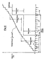
- a first pulse 34a indicates that the preset volume of the viscous material 10 has passed through the flow meter 32 during a first time period T1 and the second pulse 34b indicates that the preset volume of the viscous material 10 has passed through the flow meter 32 during a second time period T2, consecutive with the first time period T1.
- a stream of pulses 34 is transmitted.
- a pressure sensor 36 is positioned at the nozzle 26 to measure a pressure of the viscous material 10 as the viscous material 10 is dispensed onto the workpiece 12.
- the pressure sensor 36 includes a transducer 38 positioned within the nozzle 26 that transmits a control signal 40 that varies as the pressure of the viscous material 10 within the nozzle 26 varies.
- the pressure sensor 36 measures the pressure after each of a plurality of time increments ti while the viscous material 10 is being dispensed. In the preferred embodiment, each of the plurality of time increments ti are 0.008 seconds.
- a pressure regulator 42 is coupled to the delivery conduit 20 to control the actual dispensing rate that the viscous material 10 is dispensed through the nozzle 26 and onto the workpiece 12.
- the pressure regulator 42 includes a variable orifice servo valve 44 that is electronically responsive to an output signal 46 to open and close the variable orifice servo valve 44 thereby changing the actual dispensing rate.
- the output signal 46 comprises a voltage to be applied to the variable orifice servo valve 44 to maintain a position of the variable orifice servo valve 44. Additions or reductions to the voltage adjusts the variable orifice servo valve 44 to ensure that the viscous material 10 is being dispensed within the minimum deviation of the target dispensing rate, as will be described further below. Operation of the flow meter 32, pressure sensor 36, and pressure regulator 42 are well known to those skilled in the art and will not be described in further detail.
- a controller 48 having a microprocessor 49 is operatively and electrically connected to the flow meter 32, the pressure sensor 36, and the pressure regulator 42.
- the controller 48 is programmed to receive and interpret the pulses 34 transmitted by the flow meter 32 to measure the actual volume of the viscous material 10 dispensed over time.
- the controller 48 is also programmed to receive and interpret the control signal 40 generated by the pressure sensor 36 to determine a theoretical volume of the viscous material 10 dispensed onto the workpiece 12 overtime.
- the controller 48 compares the theoretical volume and the actual volume to derive new values for a compensation factor f , as will be described further below.
- the viscous material 10 e.g., urethanes, silicones, butyls, hot-melt materials, and the like, may have a standard viscosity between 10,000 and 500,00 cP (mPa ⁇ s).
- the viscosity of the viscous material 10 may vary due to temperature, shear thinning or thickening, and batch-to-batch changes.
- changes in the dispensing system 14 may occur such as wear of components, e.g., wear of the nozzle 26, plugging of the nozzle 26, air bubbles within the dispensing system 14, the viscous material 10 settling during breaks, and the like.
- the dispensing system 14 of the present invention utilizes the compensation factor f and closed loop control to compensate the actual dispensing rate of the viscous material 10 for changes in these operational characteristics of the viscous material 10 and the dispensing system 14 such that the actual dispensing rate is maintained within the minimum deviation of the target dispensing rate.
- the minimum deviation represents an acceptable tolerance in the actual dispensing rate. Typically, such tolerances are on the order of ten percent, i.e., the actual dispensing rate is within ten percent of the target dispensing rate.
- Operation of the dispensing system 14 is based on the pressure measurements P taken while dispensing the viscous material 10 onto the workpiece 12. In other words, dispensing of the viscous material 10 onto the workpiece 12 is pressure controlled.
- the pressure of the viscous material 10 is measured after each of the plurality of time increments ti as the viscous material 10 is dispensed.
- the pressure sensor 36 transmits the control signal 40 to the controller 48 after each of the plurality of time increments ti and the controller 48, receiving the control signal 40, converts the control signal 40 into the press-are measurements P.
- the cracking pressure b represents the minimum pressure for the viscous material 10 to begin dispensing from the dispensing system 14 onto the workpiece 12. i.e., the cracking pressure b compensates for frictional losses within the dispensing system 14.
- the linearity factor N corresponds to shear thinning or shear thickening properties of the viscous material 10.
- the linearity factor N may be less than one for shear-thickening, greater than one for shear-thinning, and equal to one for linear material.
- the cracking pressure b and linearity factor N can be established based on trial and error using the above equation or by other methods such as manufacturer's suggestions and the like. Determination, e.g., calculation, of the compensation factor f is described further below.
- the corresponding theoretical dispensing rate is compared to the target dispensing rate.
- the dispensing system 14 is then adjusted based on the difference between the theoretical dispensing rate and the target dispensing rate. More specifically, the variable orifice servo valve 44 is adjusted. For example, if the theoretical dispensing rate is greater than the target dispensing rate, the variable orifice servo valve 44 partially closes flow of the viscous material 10, and if the theoretical dispensing rate is less than the target dispensing rate the variable orifice servo valve 44 partially opens flow of the viscous material 10.
- the variable orifice servo valve 44 is adjusted by adjusting the voltage of the output signal 46 applied thereto.
- the voltage of the output signal 46 comprises a base voltage 50, a first voltage adjustment 52, and a second voltage adjustment 54.
- the base voltage is predefined, for example, by a relationship such as base voltage - A * target dispensing rate + initial voltage wherein A is a constant. Referring specifically to FIG. 1, once the difference between the theoretical dispensing rate and the target dispensing rate is determined after each time increment, the difference is multiplied by a first voltage constant K 0 to determine the first voltage adjustment 52.
- the first voltage adjustment 52 can be an addition or reduction of the voltage of the output signal 46 applied to the variable orifice servo valve 44 to ensure that the actual dispensing rate is within the minimum deviation of the target dispensing rate.
- the second voltage adjustment 54 is described further below in reference to additional compensation routines.
- This method of controlling the dispensing system 14 to dispense the viscous material 10 would not be ideal without the compensation factor f to determine the theoretical dispensing rate. Controlling the dispensing system 14 based on the theoretical dispensing rate, without the compensation factor f , would not account for many of the changes in the operating characteristics of the viscous material 10 and the dispensing system 14. Hence, the dispensing system 14 would be prone to errors, resulting in wasted time and increased product defects. For this reason, the compensation factor f is utilized.
- the compensation factor f is utilized during operation of the dispensing system 14 to compensate the actual dispensing rate and maintain the actual dispensing rate within the minimum deviation of the target dispensing rate.
- the compensation factor f therefore, must be continuously updated, i.e., recalculated, to compensate for changes in the operational characteristics of the viscous material 10 and the dispensing system 14.
- the compensation factor f is determined, i.e., recalculated, after every pulse 34 that is transmitted to the controller 48 by the flow meter 32. Since the flow meter 32 can provide accurate volumetric measurements of the viscous material 10 dispensed over a given time period, these measurements are used to determine the compensation factor f. Of course, as previously noted, these measurements occur approximately once every 0.09 to 0.12 seconds in a typical dispensing application.
- the compensation factor f is determined during operation of the dispensing system 14, i.e., while dispensing the viscous material 10 onto the workpiece 12. As the viscous material 10 is dispensed, the pressure measurements P are being taken after each of the plurality of time increments ti. Referring to FIG. 4, a theoretical volume of the viscous material 10 dispensed during a first time period T1 is determined based on the pressure measurements P taken during the first time period T1 and an initial value f initial for the compensation factor f.
- the actual volume of the viscous material 10 dispensed during the first time period T1 is measured. In the preferred embodiment, this is simply the preset volume of the flow meter 32, i.e., the volume of the viscous material 10 dispensed between commencement of dispensing at time equals zero in FIG. 4, and the first pulse 34a from the flow meter 32, also shown in FIG. 4.
- the controller 48 compares the theoretical and actual volumes of the viscous material 10 dispensed during the first time period T1 to determine a first new value F 1 for the compensation factor f.
- F 1 is the first new value for the compensation factor f
- b is the cracking pressure
- P ti is the pressure measurement taken at each time increment ti within the first time period T 1
- N is the linearity factor.
- the first new value f 1 for the compensation factor f accounts for changes in operational characteristics of the viscous material 10 and the dispensing system 14 that occurred during the first time period T1. Hence, the first new value f 1 for the compensation factor f can now be used for normal operation of the dispensing system 14 in a second time period T2 , consecutive with the first time period T1.
- the method continues by dispensing the viscous material 10 onto the workpiece 12 during the second time period T2 .
- the same steps carried out for the first time period T1 are performed during the second time period T2 to determine a-second new value f 2 for the compensation factor f for the second time period T2 , namely, measuring a pressure of the viscous material 10 after each of a plurality of time increments ti within the second time period T2 , determining a theoretical volume of the viscous material 10 dispensed during the second time period T2 based on the pressure measurements P during the second time period T2 and the first new compensation factor f 1 , measuring an actual volume of the viscous material 10 dispensed during the second time period T2, and comparing the theoretical and actual volumes of the viscous material 10 dispensed during the second time period T2 to determine the second new value f 2 for the compensation factor f based on the comparison between the theoretical and actual volumes of the viscous material 10 dispensed during the second
- the method of determining the first f 1 and second f 2 new values for the compensation factor f is characterized by at least a portion of the second time period T2 occurring consecutively with the first time period T1 to compensate the actual dispensing rate in the second time period T2 for changes in the operational characteristics of the viscous material 10 and the dispensing system 14 that occurred in the first time period T1 thereby maintaining the actual dispensing rate within the minimum deviation of the target dispensing rate.
- a new value for the compensation factor is determined after each pulse 34 is transmitted by the flow meter 32, i.e., the compensation factor f is recalculated after each pulse 34.
- the previous description of how to determine the first f 1 and second f 2 new values for the compensation factor f is merely illustrative of the steps carried out to recalculate the compensation factor f after each pulse 34.
- the compensation factor f could be recalculated hundreds or thousands of times during the dispensing application.
- a theoretical accumulated volume of the viscous material 10 dispensed over the first T1 and second T2 time periods is determined.
- the theoretical accumulated volume is based on both the theoretical volume and the actual volume.
- the theoretical accumulated volume is based on the theoretical volume between pulses 34a, 34b, and the actual volume at each pulse 34a, 34b.
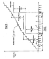
- the theoretical accumulated volume is adjusted at each pulse 34a, 34b to a total actual volume of viscous material 10 dispensed based on the preset volume of the flow meter 32, as illustrated in FIG. 5.
- a target accumulated volume of the viscous material 10 dispensed over the first T1 and second T2 time periods is determined based on the target dispensing rate, e.g., the target dispensing rate * time. These accumulated volumes are then compared and the voltage of the output signal 46 applied to the variable orifice servo valve 44 is further adjusted based on the difference between the theoretical accumulated volume and the target accumulated volume. In particular, referring to FIG. 1, the difference is multiplied by a second voltage constant K 1 to determine the second voltage adjustment 54.
- the second voltage adjustment 54 is an addition or reduction in the voltage of the output signal 46 applied to the variable orifice servo valve 44.
- the voltage applied to the variable orifice servo valve 44 via the output signal 46 is equal to the base voltage 50 plus the first 52 and second 54 voltage adjustments.
- the first voltage adjustment 52, as with the second voltage adjustment 54, is executed after each pressure measurement P , or every 0.008 seconds.
- the compensation factor f can also be used to detect changes in the operational characteristics of the dispensing system 14. In particular, if changes in the value for the compensation factor f between pulses 34 exceeds a predetermined limit, e.g., if the difference between the first new value f 1 for the compensation factor f and the second new value f 2 for the compensation factor f exceeds the predetermined limit, the nozzle 26 may be plugged and the controller 48 may send an indicator signal to an operator of the dispensing system 14 indicating the same. In addition, the controller 48 may shut down the dispensing system 14 until the condition is returned to normal, i.e., the nozzle 26 is unplugged.
- a predetermined limit e.g., if the difference between the first new value f 1 for the compensation factor f and the second new value f 2 for the compensation factor f exceeds the predetermined limit
- the compensation factor f could similarly be used to detect air bubbles within the dispensing system 14 based on the difference between the first f 1 and second f 2 new values for the compensation factor f.
- a second predetermined limit may be defined to detect air bubbles with the dispensing system 14.
- a plugged nozzle or air bubbles in the dispensing system 14 can be detected by a large change in the compensation factor f within a short time period.
- the compensation factor f could similarly be used to detect undesired "gumdrop” dispensing, i.e., when large drops of the viscous material 10 are dispensed onto the workpiece 12 as opposed to a steady flow.
- wear of the nozzle 26 of the dispensing system 14 could be detected based on exceeding a predefined limit for the value for the compensation factor f.
- the predefined limit being a value of the compensation factor f in which the nozzle 26 is close to being worn and must be replaced due to excessive wear.
- the controller 48 may calculate a trend line for each successively determined value of the compensation factor f during the dispensing application. If the trend line does not sharply move, e.g., indicating that the nozzle 26 is plugged or air bubbles are in the dispensing system 14, and the trend line passes through the predefined limit, i.e., exceeds the predefined limit, an indicator signal maybe sent to the operator indicating that the nozzle 26 should be replaced.
- a portion of the second time period T2 overlaps the first time period T1 such that the second time period T2 includes the first time period T1 to compensate the actual dispensing rate for changes in the operating characteristics of the viscous material 10 and the dispensing system 14 thereby maintaining the actual dispensing rate within the minimum deviation of the target dispensing rate.
- This alternative may provide a better averaging method for the compensation factor f by utilizing more historical pressure and volume data.
- all other steps from the previous embodiment are carried out in this embodiment.
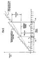
- N is assigned a constant value.
- Figure 7 contains graphs representing the trend of delivery rate-fluid pressure data sets that would result with values of N that are greater than, less than and equal to unity.
- N is assigned a value that corresponds to expected trends of the delivery rate-fluid pressure data sets.
- the controller 48 receives a pressure signal 40, converts the signal to a pressure magnitude P, and stores the pressure magnitude P in electronic memory accessible to the microprocessor 49.
- the controller 48 calculates the average delivery or fluid flow rate D ave through the delivery flow meter 32, and the average pressure magnitude P ave from the pressure signals that have occurred at each increment ti since a prior pulse 34.
- the pressure and flow rate magnitudes are averaged over a period during which several delivery meter pulses 34 have occurred.
- the pressure and delivery rate values are also recorded in electronic memory. After several sets of (P, D) values are obtained, the coefficients F and B are calculated using a least square method.
- the controller 48 performs calculations using data acquired over a period containing several delivery meter pulses 34, instead of using pressure data of only one previous pulse from the delivery flow meter 32.
- the controller 48 calculates, not only the compensation factor F, but also the pressure bias / cracking pressure B.
- the controller 48 only retains a certain number of old (P, D) data sets so that only the recent measurement data reflect viscosity changes of the material. In order to accomplish this, the recorded P and D data are retained in a ring buffer having a predefined size. During one pulse increment, the controller 48 uses the average value for the measured pressure. Provided the relationship between D and P is linear, this averaging is permitted.
- the buffer ring no longer records and retains the data at a higher rate. Similarly, if the number of pressure and delivery data sets at a higher rate decreases to a predetermined number, the ring no longer records and retains the data at a lower rate. This ensures that the ring buffer always contains data at a lower rate and a higher rate so that accurate coefficients are calculated.
- the system 14 posts a "Bubble Detected” alarm.
- the delivery meter 32 measures a flow rate lower than the one given by Equation (2) for the measured pressure, the system posts a "Partially Plug-tip Detected” alarm.
- the system retains reference values, F 0 and B 0 , of F and B in order to determine whether the nozzle is excessively worn.
- D Fo * P + Bo If the latest calculated F and B values result in a calculated theoretical flow rate that is greater than the flow rate from Equation (3), then the system posts a "Worn Out Nozzle" alarm.
- the number of delivery conduits or guns 20 is a part of the material delivery system.
- Equation (4) assumes that the resistance within the gun hose or conduit 20 is negligible, and the number of guns g that are opened for one delivery meter increment T is unchanged.
- Equation (4) upon replacing D/g with D, the same least square method calculation can be applied to a system operating with multiple guns operating concurrently. If the number of guns changes during a time increment, then the measurement data for that period are discarded.
Landscapes
- Physics & Mathematics (AREA)
- Fluid Mechanics (AREA)
- Application Of Or Painting With Fluid Materials (AREA)
- Coating Apparatus (AREA)
Claims (22)
- Fluidabgabesystem (14) zum Abgeben eines Fluids (10) auf ein Werkstück (12) über einen Ausgang (26) bei einer Sollflussrate, wobei das System aufweist:eine steuerbare Druckregelvorrichtung (42), durch die das Fluid (10) unter Druck zu dem Ausgang (26) fließt;einen Drucksensor (36), der ein Drucksignal bereit stellt, das einen Fluiddruck an dem Ausgang (26) angibt;ein Flussmessgerät (32), das ein Flussratensignal bereit stellt, das eine Flussrate des Fluids (10) durch den Ausgang (26) angibt; undeinen Controller (48), der auf das Flussratensignal anspricht, um die Druckregelvorrichtung (42) zu steuern, um einen Druck zu erzeugen, der der Sollflussrate entspricht, dadurch gekennzeichnet, dassdie Sollflussrate und das Drucksignal über einen Kompensationsfaktor und einen Abreissdruck miteinander in Beziehung stehen, der von dem Controller (48) auf der Grundlage der Flussrate, die durch das Flussratensignal angegeben ist, und des Fluiddrucks berechnet wird, der von dem Drucksignal angegeben ist.
- System nach Anspruch 1, dadurch gekennzeichnet, dass die Druckregelvorrichtung (42) ein Servoventil (44) aufweist, das eine Öffnung mit variablem Querschnittsbereich aufweist, durch das das Fluid (10) unter Druck zu dem Ausgang (26) fliesst.
- System nach Anspruch 1, dadurch gekennzeichnet, dass ein Roboter (28) mit einem Roboterarm (30) zum Steuern einer Position des Ausgangs (26) relativ zu dem Werkstück (12) an dem Ausgang (26) angreift.
- System nach Anspruch 1, dadurch gekennzeichnet, dass die Druckregelvorrichtung (42) ein Servoventil (44) mit variabler Öffnung aufweist und der Controller (48) programmiert ist, um das Servoventil (44) mit variabler Öffnung unter Verwendung eines Unterschieds zwischen der Sollflussrate und der durch das Flussratensignal angegebenen Flussrate durch den Ausgang (26) zu regulieren.
- System nach Anspruch 1, dadurch gekennzeichnet, dass der Ausgang (26) mit einer Zufuhrleitung (20) verbunden ist und eine Pumpe (18) mit der Zufuhrleitung (20) gekoppelt ist, um das Fluid (14) durch die Zufuhrleitung (20) zu dem Ausgang (26) zu fördern.
- System nach Anspruch 1, dadurch gekennzeichnet, dass ein Roboter (28) mit einem Roboterarm (30) an dem Ausgang (26) angreift, um eine Position des Ausgangs (26) relativ zu dem Werkstück (12) zu steuern, wobei der Roboter (28) sechs Drehachsen zum Drehen von einem des Ausgangs (26) und des Werkstücks (12) darum definiert.
- Verfahren zum Steuern eines Fluidabgabesystems (14), das eine steuerbare Druckregelvorrichtung (24) aufweist, durch die Fluid (10) unter Druck zu einem Ausgang (26) mit einer Sollflussrate fliesst, dadurch gekennzeichnet, dass das Verfahren die Schritte aufweist:Festlegen eines anfänglichen Kompensationsfaktors und eines anfänglichen Abreissdrucks;Messen eines Drucks des Fluids bei jedem einer Mehrzahl von Zeitinkrementen, die auftreten, während das Fluid (10) abgegeben wird;Ermitteln eines Volumens des Fluids (10), das während eines ersten Zeitabschnitts abgegeben wird;Ermitteln eines mittleren Drucks bei den Zeitinkrementen während des ersten Zeitabschnitts;Ermitteln einer mittleren Flussrate während des ersten Zeitabschnitts;Ermitteln aus dem mittleren Druckwert und dem mittleren Flussratenwert während des ersten Zeitabschnitts eines neuen Kompensationsfaktors und eines neuen Abreissdrucks;Verwenden des neuen Kompensationsfaktors, des neuen Abreissdrucks und der Druckmessungen während eines zweiten Zeitabschnitts, um eine theoretische Flussrate des Fluids (10) für den zweiten Zeitabschnitt zu ermitteln; undVerwenden eines Unterschieds zwischen der theoretischen Flussrate und der Sollflussrate, um die Druckregelvorrichtung (42) zu steuern, um einen Druck zu erzeugen, der der Sollflussrate entspricht.
- Verfahren nach Anspruch 7, dadurch gekennzeichnet, dass der Schritt, einen Druck des Fluids (10) zu messen, ferner umfasst, ein Steuersignal von einem Drucksensor (36) nach jedem der Zeitinkremente zu empfangen und die Steuersignale in die Druckmessungen umzuwandeln.
- Verfahren nach Anspruch 8, dadurch gekennzeichnet, dass der Schritt, das tatsächliche Volumen des Fluids (10) zu ermitteln, das während des ersten Zeitabschnitts abgegeben wird, ferner umfasst, erste und zweite elektrische Pulse zu erhalten, die von einem Flussmessgerät (32) des Abgabesystems (14) erzeugt werden, wobei der erste Puls angibt, dass ein vorab festgelegtes Volumen des Fluids (10) während einer ersten Zeitdauer durch das Flussmessgerät (32) hindurch gegangen ist, und der zweite Puls angibt, dass das vorab festgelegte Volumen des Fluids (10) während einer zweiten Zeitdauer durch das Flussmessgerät (32) hindurch gegangen ist, wobei sich die ersten und zweiten Dauern zu dem ersten Zeitabschnitt erstrecken.
- Verfahren nach Anspruch 9, dadurch gekennzeichnet, dass ein weiterer Schritt umfasst, die theoretische Flussrate zu ermitteln, nachdem jede Druckmessung vorgenommen wurde.
- Verfahren nach Anspruch 10, dadurch gekennzeichnet, dass ein weiterer Schritt umfasst, die theoretische Flussrate mit der Sollflussrate zu vergleichen und eine Spannung, die an ein Servoventil (44) mit variabler Öffnung der Druckregelvorrichtung (42) angelegt wird, auf der Grundlage eines Unterschieds zwischen der theoretischen Flussrate und der Sollflussrate einzustellen.
- Verfahren nach Anspruch 11, dadurch gekennzeichnet, dass ein weiterer Schritt umfasst, ein theoretisches akkumuliertes Volumen des Fluids (10), das während des ersten Zeitabschnitts abgegeben wird, zu ermitteln und ein akkumuliertes Sollvolumen des Fluids (10) zu ermitteln, das während des ersten Zeitabschnitts abgegeben wird.
- Verfahren nach Anspruch 12, dadurch gekennzeichnet, dass ein weiterer Schritt umfasst, das theoretische akkumulierte Volumen und das akkumulierte Sollvolumen zu vergleichen und die an das Servoventil (44) mit variabler Öffnung angelegte Spannung auf der Grundlage eines Unterschieds zwischen dem theoretischen akkumulierten Volumen und dem akkumulierten Sollvolumen einzustellen.
- Verfahren nach Anspruch 7, dadurch gekennzeichnet, dass die Schritte, einen anfänglichen Abreissdruck festzulegen und einen Abreissdruck zu ermitteln, umfasst, einen Druck zu ermitteln, der Reibungsverluste in dem Abgabesystem (15) angibt, die von dem Fluid (10) zu überwinden sind, um damit zu beginnen, Fluid (10) auf ein Werkstück (12) abzugeben.
- Verfahren nach Anspruch !$, dadurch gekennzeichnet, dass ein weiterer Schritt umfasst, in Linearitätsmaß (N) für das Fluid (10) festzulegen, dass Scherentzähnungs- oder Scherverdickungseigenschaften des Fluids (10) angibt.
- Verfahren nach Anspruch 7, dadurch gekennzeichnet, dass der Schritt, die theoretische Flussrate des Fluids zu ermitteln ferner umfasst, die theoretische Flussrate unter Verwendung des Verhältnisses D = F * P + B zu ermitteln, wobei D die (theoretische Flussrate)n ist; n = 1 / N, eine Konstante; P Fluiddruck ist; F = fn; und B = - F * b; b der Abreissdruck ist; f der Kompensationsfaktor ist; und n ein Linearitätsmaß ist.
- Verfahren nach Anspruch 16, dadurch gekennzeichnet, dass die Werte von F und B unter Verwendung von F = Spd / Spp; und B = Dave F * Pave berechnet werden, wobei

und t die Anzahl an Zeitinkrementen ist. - Verfahren nach Anspruch 7, dadurch gekennzeichnet, dass ein weiterer Schritt umfasst, auf der Grundlage eines Unterschieds zwischen einer von einem Flussmessgerät (32) angegebenen Flussrate und einer theoretischen Flussrate, die kleiner als die von dem Flussmessgerät (32) angegebene Flussrate ist, ein Hindernis in dem Abgabesystem (14) zu detektieren.
- Verfahren nach Anspruch 7, dadurch gekennzeichnet, dass ein weiterer Schritt umfasst, auf der Grundlage eines Unterschieds zwischen einer von einem Flussmessgeräte (32) angegebenen Flussrate und einer theoretischen Flussrate, die größer als die von dem Flussmessgerät (32) angegebene Flussrate ist, Gasblasen in dem Abgabesystem (14) zu detektieren.
- Verfahren nach Anspruch 7, dadurch gekennzeichnet, dass ein weiterer Schritt umfasst, Referenzwerte des Kompensationsfaktors und des Abreissdrucks festzulegen und Verschleiss einer Düse (26) des Abgabesystem (14) auf der Grundlage einer ersten theoretischen Flussrate, die unter Verwendung der Referenzwerte des Kompensationsfaktors und des Abreissdrucks und der Druckmessungen für einen Zeitabschnitt ermittelt wird, und einer zweiten theoretischen Flussrate zu detektieren, die unter Verwendung eines neues Kompensationsfaktors und eines neuen Abreissdrucks und von Druckmessungen für den genannten Zeitabschnitt ermittelt wird, die größer als die erste theoretische Flussrate ist.
- Verfahren nach Anspruch 7, dadurch gekennzeichnet, dass der gesamte zweite Zeitabschnitt nach dem ersten Zeitabschnitt auftritt, um eine tatsächliche Flussrate während des zweiten Zeitabschnitts hinsichtlich Änderungen in einer Betriebseigenschaft des Fluids (10) und des Abgabesystems (14) zu kompensieren, die während des ersten Zeitabschnitts auftreten, wodurch die tatsächliche Flussrate mit einer minimalen Abweichung von der Sollflussrate während des zweiten Zeitabschnitts beibehalten wird.
- Verfahren nach Anspruch 7, dadurch gekennzeichnet, dass ein Teil des zweiten Zeitabschnitts mit dem ersten Zeitabschnitt überlappt, um eine tatsächliche Flussrate während des zweiten Zeitabschnitts hinsichtlich von Änderungen in einer Betriebseigenschaft des Fluids (10) und des Abgabesystems (14) zu kompensieren, die während des ersten Zeitabschnitts auftreten, um dadurch die tatsächliche Flussrate mit einer minimalen Abweichung von der Sollflussrate beizubehalten.
Applications Claiming Priority (3)
| Application Number | Priority Date | Filing Date | Title |
|---|---|---|---|
| US10/649,977 US20050048195A1 (en) | 2003-08-26 | 2003-08-26 | Dispensing system and method of controlling the same |
| US10/738,841 US20050048196A1 (en) | 2003-08-26 | 2003-12-17 | Control and system for dispensing fluid material |
| PCT/US2004/027835 WO2005018826A1 (en) | 2003-08-26 | 2004-08-26 | Control and system for dispensing fluid material |
Publications (2)
| Publication Number | Publication Date |
|---|---|
| EP1658145A1 EP1658145A1 (de) | 2006-05-24 |
| EP1658145B1 true EP1658145B1 (de) | 2007-05-09 |
Family
ID=34221846
Family Applications (1)
| Application Number | Title | Priority Date | Filing Date |
|---|---|---|---|
| EP04782333A Expired - Fee Related EP1658145B1 (de) | 2003-08-26 | 2004-08-26 | Steuerung und system zur abgabe von fluidmaterial |
Country Status (6)
| Country | Link |
|---|---|
| US (2) | US20050048195A1 (de) |
| EP (1) | EP1658145B1 (de) |
| JP (1) | JP2007503982A (de) |
| CN (1) | CN100411748C (de) |
| DE (1) | DE602004006425T2 (de) |
| WO (1) | WO2005018826A1 (de) |
Cited By (1)
| Publication number | Priority date | Publication date | Assignee | Title |
|---|---|---|---|---|
| DE102022100401A1 (de) | 2022-01-10 | 2023-07-13 | Dürr Systems Ag | Applikationsanlage und zugehöriges Überwachungsverfahren |
Families Citing this family (42)
| Publication number | Priority date | Publication date | Assignee | Title |
|---|---|---|---|---|
| US20050098578A1 (en) * | 2002-09-13 | 2005-05-12 | Ford Motor Company | System for dispensing reactant mixtures |
| GB2424966B (en) * | 2005-04-07 | 2007-03-21 | Geoffrey David Taylor | Method and apparatus for monitoring fluid flow |
| DE102006026051A1 (de) * | 2006-05-31 | 2007-12-06 | Abb Patent Gmbh | Verfahren zur Ermittlung einer benötigten Lackmenge |
| TW200800411A (en) * | 2006-06-28 | 2008-01-01 | Nordson Corp | Conformal coating system with closed loop control |
| JP5399011B2 (ja) * | 2007-06-28 | 2014-01-29 | 三菱化学メディエンス株式会社 | 組織傷害あるいは細胞増殖性疾患の検出方法 |
| CN101873989A (zh) * | 2007-11-29 | 2010-10-27 | 诺信公司 | 分配粘性材料的方法 |
| WO2010146928A1 (ja) * | 2009-06-19 | 2010-12-23 | タツモ株式会社 | 基板用塗布装置 |
| WO2011084727A2 (en) * | 2009-12-21 | 2011-07-14 | Henkel Corporation | Method and system for regulating adhesive application |
| WO2011123503A1 (en) | 2010-04-01 | 2011-10-06 | B & H Manufacturing Company, Inc. | Extrusion application system |
| US20130105004A1 (en) * | 2011-10-27 | 2013-05-02 | Graco Minnesota Inc. | Hot melt dispensing system with heated accumulator |
| KR101420488B1 (ko) * | 2012-01-31 | 2014-07-16 | 삼성전기주식회사 | 노즐 상태 모니터링 장치 |
| US9113591B2 (en) | 2012-06-18 | 2015-08-25 | Raven Industries, Inc. | Implement for adjustably metering an agricultural field input according to different frame sections |
| US9847265B2 (en) | 2012-11-21 | 2017-12-19 | Nordson Corporation | Flow metering for dispense monitoring and control |
| US9393586B2 (en) * | 2012-11-21 | 2016-07-19 | Nordson Corporation | Dispenser and method of dispensing and controlling with a flow meter |
| JP5994066B2 (ja) * | 2013-01-08 | 2016-09-21 | 兵神装備株式会社 | 塗布状態検知システム、及び塗布システム |
| BR112016008517B1 (pt) | 2013-10-17 | 2021-06-22 | Raven Industries, Inc | Método e sistema para controlar taxa de fluxo de bocal de um produto agrícola em um aspersor agrícola, sistema de controle de aspersor e método para controlar características de aspersão de bocais de aspersão em um sistema aspersor |
| US10173236B2 (en) | 2013-10-17 | 2019-01-08 | Raven Industries, Inc. | Nozzle control system and method |
| JP6085578B2 (ja) * | 2014-03-11 | 2017-02-22 | 住友重機械工業株式会社 | 膜形成方法及び膜形成装置 |
| CN103894312B (zh) * | 2014-03-28 | 2016-04-13 | 郑州格兰高环境工程有限公司 | 智能移动式胶水补给系统 |
| DE102014004718A1 (de) * | 2014-04-01 | 2015-10-01 | Eisenmann Ag | Beschichtungssystem und Verfahren zum Beschichten von Gegenständen |
| JP6636945B2 (ja) * | 2014-05-01 | 2020-01-29 | グラコ ミネソタ インコーポレーテッド | 過渡状態のシステムにおける流量制御の補正方法 |
| TW201600735A (zh) | 2014-05-01 | 2016-01-01 | 葛萊兒明尼蘇達股份有限公司 | 用於封閉系統中之液壓控制之方法 |
| US20160256883A1 (en) * | 2015-03-02 | 2016-09-08 | Wagner Spray Tech Corporation | Liquid dispensing system with improved pressure control |
| KR102195485B1 (ko) * | 2016-01-21 | 2020-12-29 | 엘에스엠트론 주식회사 | 사출 성형기의 윤활 조건 설정 방법 |
| US11097286B2 (en) * | 2017-01-05 | 2021-08-24 | Wagner Spray Tech Corporation | High efficiency airless spray tip design and use |
| CN106694319B (zh) * | 2017-03-22 | 2019-06-18 | 京东方科技集团股份有限公司 | 曲面涂布装置及涂胶设备 |
| US10335823B2 (en) * | 2017-03-30 | 2019-07-02 | The Boeing Company | Apparatuses for applying glutinous substances to seams |
| DE102018004990A1 (de) | 2017-06-23 | 2018-12-27 | Sm-Klebetechnik Vertriebs Gmbh | Vorrichtung und Verfahren zum Leiten einer Flüssigkeit in einer Leitung |
| DE102017119439A1 (de) * | 2017-08-24 | 2019-02-28 | Khs Gmbh | Verfahren zum Steuern der Menge eines auf einen Träger aufzubringenden Klebemittels |
| JP6920923B2 (ja) * | 2017-08-25 | 2021-08-18 | 株式会社Screenホールディングス | ポンプ装置および基板処理装置 |
| US11185879B2 (en) * | 2018-02-08 | 2021-11-30 | Nordson Corporation | Systems and methods for calibrating flow and for coating a substrate |
| FR3078900B1 (fr) * | 2018-03-15 | 2020-09-18 | Exel Ind | Dispositif d'application d'un produit fluide dont le debit de dosage depend de la vitesse d'un orifice de sortie dudit produit fluide |
| JP7101036B2 (ja) * | 2018-04-26 | 2022-07-14 | 東京エレクトロン株式会社 | 処理液供給装置及び処理液供給方法 |
| DE102018124745A1 (de) * | 2018-10-08 | 2020-04-09 | Webasto SE | Vorrichtung und Verfahren zum Bearbeiten eines plattenförmigen Werkstücks für ein Kraftfahrzeug |
| EP3911446A4 (de) * | 2019-01-18 | 2022-10-19 | Wagner Spray Tech Corporation | Intelligente steuerung eines sprühsystems |
| US10935477B2 (en) | 2019-03-27 | 2021-03-02 | Ford Motor Company | Method and apparatus for automatic detection of entrapped gas bubble location and repairing the same in dispensed adhesives, sealants, and mastics |
| DE102019109208B3 (de) * | 2019-04-08 | 2020-10-01 | Dürr Systems Ag | Applikationseinrichtung und entsprechendes Applikationsverfahren |
| US11513602B2 (en) | 2019-09-10 | 2022-11-29 | Wagner Spray Tech Corporation | Gesture control of a fluid application system |
| US11612160B2 (en) | 2019-10-04 | 2023-03-28 | Raven Industries, Inc. | Valve control system and method |
| DE102020130472A1 (de) | 2020-11-18 | 2022-05-19 | Focke & Co. (Gmbh & Co. Kg) | Auftragsvorrichtung zum Aufbringen von fließfähigem Medium auf ein Substrat |
| US11826768B2 (en) * | 2021-03-11 | 2023-11-28 | Ford Global Technologies, Llc | Method and apparatus for adaptive control and real-time edge tracking of adhesive and sealer dispensing |
| CN114860006B (zh) * | 2022-04-15 | 2024-01-16 | 青岛明华电子仪器有限公司 | 一种气体流量控制装置的浓度补偿方法 |
Family Cites Families (28)
| Publication number | Priority date | Publication date | Assignee | Title |
|---|---|---|---|---|
| US4472967A (en) * | 1981-04-28 | 1984-09-25 | Milliken Research Corporation | Flow controller |
| US4430886A (en) * | 1982-01-15 | 1984-02-14 | Nordson Corporation | Method and apparatus for sensing clogged nozzle |
| US4662540A (en) * | 1984-02-16 | 1987-05-05 | Robotics Incorporated | Apparatus for dispensing medium to high viscosity liquids with liquid flow detector and alarm |
| US4922852A (en) * | 1986-10-30 | 1990-05-08 | Nordson Corporation | Apparatus for dispensing fluid materials |
| US5054650A (en) * | 1986-10-30 | 1991-10-08 | Nordson Corporation | Method of compensating for changes in the flow characteristics of a dispensed fluid to maintain the volume of dispensed fluid at a setpoint |
| US5065695A (en) * | 1989-06-16 | 1991-11-19 | Nordson Corporation | Apparatus for compensating for non-linear flow characteristics in dispensing a coating material |
| US5215253A (en) * | 1990-08-30 | 1993-06-01 | Nordson Corporation | Method and apparatus for forming and dispersing single and multiple phase coating material containing fluid diluent |
| US5182938A (en) * | 1991-02-22 | 1993-02-02 | Nordson Corporation | Method and apparatus for detecting bubbles in pressurized liquid dispensing systems |
| US5207352A (en) * | 1991-04-19 | 1993-05-04 | Nordson Corporation | Method and apparatus for dispensing high viscosity fluid materials |
| US5320250A (en) * | 1991-12-02 | 1994-06-14 | Asymptotic Technologies, Inc. | Method for rapid dispensing of minute quantities of viscous material |
| US5823387A (en) * | 1993-05-18 | 1998-10-20 | Colgate-Palmolive Company | Method and apparatus for simultaneously dispensing viscous materials |
| US5475614A (en) * | 1994-01-13 | 1995-12-12 | Micro-Trak Systems, Inc. | Method and apparatus for controlling a variable fluid delivery system |
| US5494191A (en) * | 1994-05-02 | 1996-02-27 | Core Incorporated | Fluid containing and dispensing system |
| US6302306B1 (en) * | 1994-12-27 | 2001-10-16 | Visteon Global Tech., Inc. | Method and apparatus for dispensing viscous material |
| US5847285A (en) * | 1996-09-20 | 1998-12-08 | Box; Gary W. | Volume compensating pressure regulated flow control dispensing system |
| US5747102A (en) * | 1995-11-16 | 1998-05-05 | Nordson Corporation | Method and apparatus for dispensing small amounts of liquid material |
| SE508434C2 (sv) * | 1996-02-23 | 1998-10-05 | Scanrex Automation Ab | Metod och system vid dosering |
| US5823398A (en) * | 1996-07-26 | 1998-10-20 | Russillo; Rhonda L. | Valve assembly for dispensing condiments |
| US6112588A (en) * | 1996-10-25 | 2000-09-05 | Speedline Technologies, Inc. | Method and apparatus for measuring the size of drops of a viscous material dispensed from a dispensing system |
| US5823389A (en) * | 1996-12-26 | 1998-10-20 | Fanuc Robotics North America, Inc. | Apparatus and method for dispensing fluid material |
| US5918648A (en) * | 1997-02-21 | 1999-07-06 | Speedline Techologies, Inc. | Method and apparatus for measuring volume |
| US6173864B1 (en) * | 1999-04-23 | 2001-01-16 | Nordson Corporation | Viscous material dispensing system and method with feedback control |
| US20030041903A1 (en) * | 2001-09-05 | 2003-03-06 | Tsunou Chang | Method of dispensing adhesive and sealant |
| US7086861B2 (en) * | 2002-03-01 | 2006-08-08 | Pitz Richard J | System for dispensing viscous materials |
| US6722536B2 (en) * | 2002-05-13 | 2004-04-20 | Smith Kline Beecham Corporation | Nozzle for dispensing viscous material |
| CN1204976C (zh) * | 2002-11-15 | 2005-06-08 | 韩军 | 一种喷雾降温除尘系统 |
| US7063097B2 (en) * | 2003-03-28 | 2006-06-20 | Advanced Technology Materials, Inc. | In-situ gas blending and dilution system for delivery of dilute gas at a predetermined concentration |
| US7462377B2 (en) * | 2004-04-30 | 2008-12-09 | Nordson Corporation | Methods for regulating the placement of fluid dispensed from an applicator onto a workpiece |
-
2003
- 2003-08-26 US US10/649,977 patent/US20050048195A1/en not_active Abandoned
- 2003-12-17 US US10/738,841 patent/US20050048196A1/en not_active Abandoned
-
2004
- 2004-08-26 JP JP2006524870A patent/JP2007503982A/ja not_active Withdrawn
- 2004-08-26 CN CNB2004800231424A patent/CN100411748C/zh not_active Expired - Fee Related
- 2004-08-26 EP EP04782333A patent/EP1658145B1/de not_active Expired - Fee Related
- 2004-08-26 WO PCT/US2004/027835 patent/WO2005018826A1/en active IP Right Grant
- 2004-08-26 DE DE602004006425T patent/DE602004006425T2/de not_active Expired - Fee Related
Non-Patent Citations (1)
| Title |
|---|
| None * |
Cited By (2)
| Publication number | Priority date | Publication date | Assignee | Title |
|---|---|---|---|---|
| DE102022100401A1 (de) | 2022-01-10 | 2023-07-13 | Dürr Systems Ag | Applikationsanlage und zugehöriges Überwachungsverfahren |
| WO2023131583A1 (de) | 2022-01-10 | 2023-07-13 | Dürr Systems Ag | Applikationsanlage und zugehöriges überwachungsverfahren |
Also Published As
| Publication number | Publication date |
|---|---|
| JP2007503982A (ja) | 2007-03-01 |
| WO2005018826A1 (en) | 2005-03-03 |
| EP1658145A1 (de) | 2006-05-24 |
| CN1835807A (zh) | 2006-09-20 |
| US20050048195A1 (en) | 2005-03-03 |
| DE602004006425D1 (de) | 2007-06-21 |
| CN100411748C (zh) | 2008-08-20 |
| DE602004006425T2 (de) | 2008-02-07 |
| US20050048196A1 (en) | 2005-03-03 |
Similar Documents
| Publication | Publication Date | Title |
|---|---|---|
| EP1658145B1 (de) | Steuerung und system zur abgabe von fluidmaterial | |
| US5481260A (en) | Monitor for fluid dispensing system | |
| CA2017843C (en) | Method and apparatus for compensating for non-linear flow characteristics in dispensing a coating material | |
| EP0741349B1 (de) | Verfahren zur Kompensation der Fliesseigenschaftenveränderungen einer abgegebene Flüssigkeit | |
| EP2901227B1 (de) | Verfahren und vorrichtung zur selbstüberprüfung von druckbasierten masseflussreglern | |
| US9631611B2 (en) | System and method for operation of a pump | |
| KR101616582B1 (ko) | 유량 콘트롤러 | |
| US20040089234A1 (en) | System for spraying a fluid material | |
| EP0428873B1 (de) | Verfahren und Apparat zum Regulieren des Gasgehaltes in einem Schaummaterial | |
| RU2665482C2 (ru) | Наносящая система и соответствующий способ нанесения | |
| JP4195288B2 (ja) | 流体重量監視装置を備えている流体分配装置 | |
| CN109195714A (zh) | 用于监测液体粘合剂流的系统和方法 | |
| WO1988003059A1 (en) | Apparatus and method for dispensing fluid materials | |
| US8590739B2 (en) | Method for operating a pneumatic device for the metered delivery of a liquid and pneumatic device | |
| US20030041903A1 (en) | Method of dispensing adhesive and sealant | |
| US5847285A (en) | Volume compensating pressure regulated flow control dispensing system | |
| EP0764896B1 (de) | Abgabevorrichtung mit System zur druckgeregelten Mengeregelung und Volumenausgleich | |
| CN111974571A (zh) | 涂料喷涂流量控制系统 | |
| US20230323877A1 (en) | Methods for measuring fluid flow of fluid supply assembly | |
| JP2000202338A (ja) | 塗料量測定装置 |
Legal Events
| Date | Code | Title | Description |
|---|---|---|---|
| PUAI | Public reference made under article 153(3) epc to a published international application that has entered the european phase |
Free format text: ORIGINAL CODE: 0009012 |
|
| 17P | Request for examination filed |
Effective date: 20060316 |
|
| AK | Designated contracting states |
Kind code of ref document: A1 Designated state(s): DE FR GB |
|
| GRAP | Despatch of communication of intention to grant a patent |
Free format text: ORIGINAL CODE: EPIDOSNIGR1 |
|
| DAX | Request for extension of the european patent (deleted) | ||
| RBV | Designated contracting states (corrected) |
Designated state(s): DE FR GB |
|
| GRAS | Grant fee paid |
Free format text: ORIGINAL CODE: EPIDOSNIGR3 |
|
| GRAA | (expected) grant |
Free format text: ORIGINAL CODE: 0009210 |
|
| AK | Designated contracting states |
Kind code of ref document: B1 Designated state(s): DE FR GB |
|
| REG | Reference to a national code |
Ref country code: GB Ref legal event code: FG4D |
|
| REF | Corresponds to: |
Ref document number: 602004006425 Country of ref document: DE Date of ref document: 20070621 Kind code of ref document: P |
|
| EN | Fr: translation not filed | ||
| PLBE | No opposition filed within time limit |
Free format text: ORIGINAL CODE: 0009261 |
|
| STAA | Information on the status of an ep patent application or granted ep patent |
Free format text: STATUS: NO OPPOSITION FILED WITHIN TIME LIMIT |
|
| 26N | No opposition filed |
Effective date: 20080212 |
|
| PG25 | Lapsed in a contracting state [announced via postgrant information from national office to epo] |
Ref country code: FR Free format text: LAPSE BECAUSE OF FAILURE TO SUBMIT A TRANSLATION OF THE DESCRIPTION OR TO PAY THE FEE WITHIN THE PRESCRIBED TIME-LIMIT Effective date: 20080104 |
|
| PGFP | Annual fee paid to national office [announced via postgrant information from national office to epo] |
Ref country code: DE Payment date: 20080912 Year of fee payment: 5 |
|
| GBPC | Gb: european patent ceased through non-payment of renewal fee |
Effective date: 20080826 |
|
| PG25 | Lapsed in a contracting state [announced via postgrant information from national office to epo] |
Ref country code: GB Free format text: LAPSE BECAUSE OF NON-PAYMENT OF DUE FEES Effective date: 20080826 |
|
| PG25 | Lapsed in a contracting state [announced via postgrant information from national office to epo] |
Ref country code: DE Free format text: LAPSE BECAUSE OF NON-PAYMENT OF DUE FEES Effective date: 20100302 |