EP1657410A2 - Filtre catalytique - Google Patents
Filtre catalytique Download PDFInfo
- Publication number
- EP1657410A2 EP1657410A2 EP05024295A EP05024295A EP1657410A2 EP 1657410 A2 EP1657410 A2 EP 1657410A2 EP 05024295 A EP05024295 A EP 05024295A EP 05024295 A EP05024295 A EP 05024295A EP 1657410 A2 EP1657410 A2 EP 1657410A2
- Authority
- EP
- European Patent Office
- Prior art keywords
- catalytic portion
- cellular wall
- catalyst
- catalytic
- slurry
- Prior art date
- Legal status (The legal status is an assumption and is not a legal conclusion. Google has not performed a legal analysis and makes no representation as to the accuracy of the status listed.)
- Granted
Links
- 239000003054 catalyst Substances 0.000 title claims abstract description 95
- 230000003197 catalytic effect Effects 0.000 claims abstract description 169
- 230000001413 cellular effect Effects 0.000 claims abstract description 106
- 239000000758 substrate Substances 0.000 claims abstract description 90
- 239000011148 porous material Substances 0.000 claims abstract description 43
- 229910002091 carbon monoxide Inorganic materials 0.000 claims abstract description 7
- 238000011068 loading method Methods 0.000 claims description 118
- 239000002002 slurry Substances 0.000 claims description 89
- 238000011144 upstream manufacturing Methods 0.000 claims description 59
- 229910052809 inorganic oxide Inorganic materials 0.000 claims description 22
- 229910052751 metal Inorganic materials 0.000 claims description 20
- 239000002184 metal Substances 0.000 claims description 20
- 239000000843 powder Substances 0.000 claims description 16
- 239000002245 particle Substances 0.000 claims description 13
- 239000011248 coating agent Substances 0.000 claims description 11
- 238000000576 coating method Methods 0.000 claims description 11
- 238000001354 calcination Methods 0.000 claims description 8
- 230000004323 axial length Effects 0.000 claims description 6
- PNEYBMLMFCGWSK-UHFFFAOYSA-N aluminium oxide Inorganic materials [O-2].[O-2].[O-2].[Al+3].[Al+3] PNEYBMLMFCGWSK-UHFFFAOYSA-N 0.000 description 32
- 238000000746 purification Methods 0.000 description 25
- 238000003892 spreading Methods 0.000 description 24
- 230000000052 comparative effect Effects 0.000 description 12
- 238000010276 construction Methods 0.000 description 8
- 238000001035 drying Methods 0.000 description 8
- 239000000919 ceramic Substances 0.000 description 5
- 229910052878 cordierite Inorganic materials 0.000 description 4
- 239000008367 deionised water Substances 0.000 description 4
- 229910021641 deionized water Inorganic materials 0.000 description 4
- JSKIRARMQDRGJZ-UHFFFAOYSA-N dimagnesium dioxido-bis[(1-oxido-3-oxo-2,4,6,8,9-pentaoxa-1,3-disila-5,7-dialuminabicyclo[3.3.1]nonan-7-yl)oxy]silane Chemical compound [Mg++].[Mg++].[O-][Si]([O-])(O[Al]1O[Al]2O[Si](=O)O[Si]([O-])(O1)O2)O[Al]1O[Al]2O[Si](=O)O[Si]([O-])(O1)O2 JSKIRARMQDRGJZ-UHFFFAOYSA-N 0.000 description 4
- XLYOFNOQVPJJNP-UHFFFAOYSA-N water Chemical compound O XLYOFNOQVPJJNP-UHFFFAOYSA-N 0.000 description 4
- 239000000243 solution Substances 0.000 description 3
- VYPSYNLAJGMNEJ-UHFFFAOYSA-N Silicium dioxide Chemical compound O=[Si]=O VYPSYNLAJGMNEJ-UHFFFAOYSA-N 0.000 description 2
- 229910010413 TiO 2 Inorganic materials 0.000 description 2
- MCMNRKCIXSYSNV-UHFFFAOYSA-N Zirconium dioxide Chemical compound O=[Zr]=O MCMNRKCIXSYSNV-UHFFFAOYSA-N 0.000 description 2
- 239000007864 aqueous solution Substances 0.000 description 2
- 238000007664 blowing Methods 0.000 description 2
- 238000002485 combustion reaction Methods 0.000 description 2
- 239000002131 composite material Substances 0.000 description 2
- 238000000354 decomposition reaction Methods 0.000 description 2
- 230000007423 decrease Effects 0.000 description 2
- 238000006073 displacement reaction Methods 0.000 description 2
- 238000011156 evaluation Methods 0.000 description 2
- 229910052737 gold Inorganic materials 0.000 description 2
- 238000002347 injection Methods 0.000 description 2
- 239000007924 injection Substances 0.000 description 2
- 229910052741 iridium Inorganic materials 0.000 description 2
- 238000005259 measurement Methods 0.000 description 2
- 229910052763 palladium Inorganic materials 0.000 description 2
- 229910052697 platinum Inorganic materials 0.000 description 2
- 229910052761 rare earth metal Inorganic materials 0.000 description 2
- 229910052703 rhodium Inorganic materials 0.000 description 2
- 229910052707 ruthenium Inorganic materials 0.000 description 2
- 238000007789 sealing Methods 0.000 description 2
- 229910052709 silver Inorganic materials 0.000 description 2
- 239000000126 substance Substances 0.000 description 2
- 229910052723 transition metal Inorganic materials 0.000 description 2
- 150000003624 transition metals Chemical class 0.000 description 2
- 238000009423 ventilation Methods 0.000 description 2
- 229910018072 Al 2 O 3 Inorganic materials 0.000 description 1
- 229910020203 CeO Inorganic materials 0.000 description 1
- 229910004298 SiO 2 Inorganic materials 0.000 description 1
- GEIAQOFPUVMAGM-UHFFFAOYSA-N ZrO Inorganic materials [Zr]=O GEIAQOFPUVMAGM-UHFFFAOYSA-N 0.000 description 1
- 229910052681 coesite Inorganic materials 0.000 description 1
- 229910052906 cristobalite Inorganic materials 0.000 description 1
- 230000000694 effects Effects 0.000 description 1
- 230000007613 environmental effect Effects 0.000 description 1
- 239000006260 foam Substances 0.000 description 1
- 238000004519 manufacturing process Methods 0.000 description 1
- 150000002739 metals Chemical class 0.000 description 1
- 238000000034 method Methods 0.000 description 1
- 238000003801 milling Methods 0.000 description 1
- 239000000203 mixture Substances 0.000 description 1
- 238000012986 modification Methods 0.000 description 1
- 230000004048 modification Effects 0.000 description 1
- 238000002360 preparation method Methods 0.000 description 1
- 238000011160 research Methods 0.000 description 1
- 239000000377 silicon dioxide Substances 0.000 description 1
- 239000004071 soot Substances 0.000 description 1
- 229910052682 stishovite Inorganic materials 0.000 description 1
- 229910052905 tridymite Inorganic materials 0.000 description 1
Images


Classifications
-
- F—MECHANICAL ENGINEERING; LIGHTING; HEATING; WEAPONS; BLASTING
- F01—MACHINES OR ENGINES IN GENERAL; ENGINE PLANTS IN GENERAL; STEAM ENGINES
- F01N—GAS-FLOW SILENCERS OR EXHAUST APPARATUS FOR MACHINES OR ENGINES IN GENERAL; GAS-FLOW SILENCERS OR EXHAUST APPARATUS FOR INTERNAL COMBUSTION ENGINES
- F01N3/00—Exhaust or silencing apparatus having means for purifying, rendering innocuous, or otherwise treating exhaust
- F01N3/02—Exhaust or silencing apparatus having means for purifying, rendering innocuous, or otherwise treating exhaust for cooling, or for removing solid constituents of, exhaust
- F01N3/021—Exhaust or silencing apparatus having means for purifying, rendering innocuous, or otherwise treating exhaust for cooling, or for removing solid constituents of, exhaust by means of filters
- F01N3/033—Exhaust or silencing apparatus having means for purifying, rendering innocuous, or otherwise treating exhaust for cooling, or for removing solid constituents of, exhaust by means of filters in combination with other devices
- F01N3/035—Exhaust or silencing apparatus having means for purifying, rendering innocuous, or otherwise treating exhaust for cooling, or for removing solid constituents of, exhaust by means of filters in combination with other devices with catalytic reactors, e.g. catalysed diesel particulate filters
-
- B—PERFORMING OPERATIONS; TRANSPORTING
- B01—PHYSICAL OR CHEMICAL PROCESSES OR APPARATUS IN GENERAL
- B01D—SEPARATION
- B01D53/00—Separation of gases or vapours; Recovering vapours of volatile solvents from gases; Chemical or biological purification of waste gases, e.g. engine exhaust gases, smoke, fumes, flue gases, aerosols
- B01D53/34—Chemical or biological purification of waste gases
- B01D53/92—Chemical or biological purification of waste gases of engine exhaust gases
- B01D53/94—Chemical or biological purification of waste gases of engine exhaust gases by catalytic processes
- B01D53/9459—Removing one or more of nitrogen oxides, carbon monoxide, or hydrocarbons by multiple successive catalytic functions; systems with more than one different function, e.g. zone coated catalysts
- B01D53/9463—Removing one or more of nitrogen oxides, carbon monoxide, or hydrocarbons by multiple successive catalytic functions; systems with more than one different function, e.g. zone coated catalysts with catalysts positioned on one brick
- B01D53/9472—Removing one or more of nitrogen oxides, carbon monoxide, or hydrocarbons by multiple successive catalytic functions; systems with more than one different function, e.g. zone coated catalysts with catalysts positioned on one brick in different zones
-
- B—PERFORMING OPERATIONS; TRANSPORTING
- B01—PHYSICAL OR CHEMICAL PROCESSES OR APPARATUS IN GENERAL
- B01J—CHEMICAL OR PHYSICAL PROCESSES, e.g. CATALYSIS OR COLLOID CHEMISTRY; THEIR RELEVANT APPARATUS
- B01J23/00—Catalysts comprising metals or metal oxides or hydroxides, not provided for in group B01J21/00
- B01J23/38—Catalysts comprising metals or metal oxides or hydroxides, not provided for in group B01J21/00 of noble metals
- B01J23/40—Catalysts comprising metals or metal oxides or hydroxides, not provided for in group B01J21/00 of noble metals of the platinum group metals
- B01J23/42—Platinum
-
- B—PERFORMING OPERATIONS; TRANSPORTING
- B01—PHYSICAL OR CHEMICAL PROCESSES OR APPARATUS IN GENERAL
- B01J—CHEMICAL OR PHYSICAL PROCESSES, e.g. CATALYSIS OR COLLOID CHEMISTRY; THEIR RELEVANT APPARATUS
- B01J35/00—Catalysts, in general, characterised by their form or physical properties
- B01J35/19—Catalysts containing parts with different compositions
-
- B—PERFORMING OPERATIONS; TRANSPORTING
- B01—PHYSICAL OR CHEMICAL PROCESSES OR APPARATUS IN GENERAL
- B01J—CHEMICAL OR PHYSICAL PROCESSES, e.g. CATALYSIS OR COLLOID CHEMISTRY; THEIR RELEVANT APPARATUS
- B01J37/00—Processes, in general, for preparing catalysts; Processes, in general, for activation of catalysts
- B01J37/02—Impregnation, coating or precipitation
- B01J37/024—Multiple impregnation or coating
- B01J37/0244—Coatings comprising several layers
-
- F—MECHANICAL ENGINEERING; LIGHTING; HEATING; WEAPONS; BLASTING
- F01—MACHINES OR ENGINES IN GENERAL; ENGINE PLANTS IN GENERAL; STEAM ENGINES
- F01N—GAS-FLOW SILENCERS OR EXHAUST APPARATUS FOR MACHINES OR ENGINES IN GENERAL; GAS-FLOW SILENCERS OR EXHAUST APPARATUS FOR INTERNAL COMBUSTION ENGINES
- F01N3/00—Exhaust or silencing apparatus having means for purifying, rendering innocuous, or otherwise treating exhaust
- F01N3/02—Exhaust or silencing apparatus having means for purifying, rendering innocuous, or otherwise treating exhaust for cooling, or for removing solid constituents of, exhaust
- F01N3/021—Exhaust or silencing apparatus having means for purifying, rendering innocuous, or otherwise treating exhaust for cooling, or for removing solid constituents of, exhaust by means of filters
- F01N3/022—Exhaust or silencing apparatus having means for purifying, rendering innocuous, or otherwise treating exhaust for cooling, or for removing solid constituents of, exhaust by means of filters characterised by specially adapted filtering structure, e.g. honeycomb, mesh or fibrous
- F01N3/0222—Exhaust or silencing apparatus having means for purifying, rendering innocuous, or otherwise treating exhaust for cooling, or for removing solid constituents of, exhaust by means of filters characterised by specially adapted filtering structure, e.g. honeycomb, mesh or fibrous the structure being monolithic, e.g. honeycombs
-
- F—MECHANICAL ENGINEERING; LIGHTING; HEATING; WEAPONS; BLASTING
- F01—MACHINES OR ENGINES IN GENERAL; ENGINE PLANTS IN GENERAL; STEAM ENGINES
- F01N—GAS-FLOW SILENCERS OR EXHAUST APPARATUS FOR MACHINES OR ENGINES IN GENERAL; GAS-FLOW SILENCERS OR EXHAUST APPARATUS FOR INTERNAL COMBUSTION ENGINES
- F01N3/00—Exhaust or silencing apparatus having means for purifying, rendering innocuous, or otherwise treating exhaust
- F01N3/02—Exhaust or silencing apparatus having means for purifying, rendering innocuous, or otherwise treating exhaust for cooling, or for removing solid constituents of, exhaust
- F01N3/021—Exhaust or silencing apparatus having means for purifying, rendering innocuous, or otherwise treating exhaust for cooling, or for removing solid constituents of, exhaust by means of filters
- F01N3/023—Exhaust or silencing apparatus having means for purifying, rendering innocuous, or otherwise treating exhaust for cooling, or for removing solid constituents of, exhaust by means of filters using means for regenerating the filters, e.g. by burning trapped particles
- F01N3/0231—Exhaust or silencing apparatus having means for purifying, rendering innocuous, or otherwise treating exhaust for cooling, or for removing solid constituents of, exhaust by means of filters using means for regenerating the filters, e.g. by burning trapped particles using special exhaust apparatus upstream of the filter for producing nitrogen dioxide, e.g. for continuous filter regeneration systems [CRT]
-
- B—PERFORMING OPERATIONS; TRANSPORTING
- B01—PHYSICAL OR CHEMICAL PROCESSES OR APPARATUS IN GENERAL
- B01D—SEPARATION
- B01D2255/00—Catalysts
- B01D2255/10—Noble metals or compounds thereof
- B01D2255/102—Platinum group metals
- B01D2255/1021—Platinum
-
- B—PERFORMING OPERATIONS; TRANSPORTING
- B01—PHYSICAL OR CHEMICAL PROCESSES OR APPARATUS IN GENERAL
- B01D—SEPARATION
- B01D2255/00—Catalysts
- B01D2255/90—Physical characteristics of catalysts
- B01D2255/915—Catalyst supported on particulate filters
- B01D2255/9155—Wall flow filters
-
- B—PERFORMING OPERATIONS; TRANSPORTING
- B01—PHYSICAL OR CHEMICAL PROCESSES OR APPARATUS IN GENERAL
- B01D—SEPARATION
- B01D53/00—Separation of gases or vapours; Recovering vapours of volatile solvents from gases; Chemical or biological purification of waste gases, e.g. engine exhaust gases, smoke, fumes, flue gases, aerosols
- B01D53/34—Chemical or biological purification of waste gases
- B01D53/92—Chemical or biological purification of waste gases of engine exhaust gases
- B01D53/94—Chemical or biological purification of waste gases of engine exhaust gases by catalytic processes
- B01D53/9445—Simultaneously removing carbon monoxide, hydrocarbons or nitrogen oxides making use of three-way catalysts [TWC] or four-way-catalysts [FWC]
- B01D53/945—Simultaneously removing carbon monoxide, hydrocarbons or nitrogen oxides making use of three-way catalysts [TWC] or four-way-catalysts [FWC] characterised by a specific catalyst
-
- B—PERFORMING OPERATIONS; TRANSPORTING
- B01—PHYSICAL OR CHEMICAL PROCESSES OR APPARATUS IN GENERAL
- B01J—CHEMICAL OR PHYSICAL PROCESSES, e.g. CATALYSIS OR COLLOID CHEMISTRY; THEIR RELEVANT APPARATUS
- B01J35/00—Catalysts, in general, characterised by their form or physical properties
- B01J35/40—Catalysts, in general, characterised by their form or physical properties characterised by dimensions, e.g. grain size
-
- B—PERFORMING OPERATIONS; TRANSPORTING
- B01—PHYSICAL OR CHEMICAL PROCESSES OR APPARATUS IN GENERAL
- B01J—CHEMICAL OR PHYSICAL PROCESSES, e.g. CATALYSIS OR COLLOID CHEMISTRY; THEIR RELEVANT APPARATUS
- B01J37/00—Processes, in general, for preparing catalysts; Processes, in general, for activation of catalysts
- B01J37/02—Impregnation, coating or precipitation
- B01J37/024—Multiple impregnation or coating
- B01J37/0242—Coating followed by impregnation
-
- F—MECHANICAL ENGINEERING; LIGHTING; HEATING; WEAPONS; BLASTING
- F01—MACHINES OR ENGINES IN GENERAL; ENGINE PLANTS IN GENERAL; STEAM ENGINES
- F01N—GAS-FLOW SILENCERS OR EXHAUST APPARATUS FOR MACHINES OR ENGINES IN GENERAL; GAS-FLOW SILENCERS OR EXHAUST APPARATUS FOR INTERNAL COMBUSTION ENGINES
- F01N2570/00—Exhaust treating apparatus eliminating, absorbing or adsorbing specific elements or compounds
- F01N2570/10—Carbon or carbon oxides
-
- F—MECHANICAL ENGINEERING; LIGHTING; HEATING; WEAPONS; BLASTING
- F01—MACHINES OR ENGINES IN GENERAL; ENGINE PLANTS IN GENERAL; STEAM ENGINES
- F01N—GAS-FLOW SILENCERS OR EXHAUST APPARATUS FOR MACHINES OR ENGINES IN GENERAL; GAS-FLOW SILENCERS OR EXHAUST APPARATUS FOR INTERNAL COMBUSTION ENGINES
- F01N2570/00—Exhaust treating apparatus eliminating, absorbing or adsorbing specific elements or compounds
- F01N2570/12—Hydrocarbons
-
- F—MECHANICAL ENGINEERING; LIGHTING; HEATING; WEAPONS; BLASTING
- F01—MACHINES OR ENGINES IN GENERAL; ENGINE PLANTS IN GENERAL; STEAM ENGINES
- F01N—GAS-FLOW SILENCERS OR EXHAUST APPARATUS FOR MACHINES OR ENGINES IN GENERAL; GAS-FLOW SILENCERS OR EXHAUST APPARATUS FOR INTERNAL COMBUSTION ENGINES
- F01N2570/00—Exhaust treating apparatus eliminating, absorbing or adsorbing specific elements or compounds
- F01N2570/14—Nitrogen oxides
-
- Y—GENERAL TAGGING OF NEW TECHNOLOGICAL DEVELOPMENTS; GENERAL TAGGING OF CROSS-SECTIONAL TECHNOLOGIES SPANNING OVER SEVERAL SECTIONS OF THE IPC; TECHNICAL SUBJECTS COVERED BY FORMER USPC CROSS-REFERENCE ART COLLECTIONS [XRACs] AND DIGESTS
- Y02—TECHNOLOGIES OR APPLICATIONS FOR MITIGATION OR ADAPTATION AGAINST CLIMATE CHANGE
- Y02A—TECHNOLOGIES FOR ADAPTATION TO CLIMATE CHANGE
- Y02A50/00—TECHNOLOGIES FOR ADAPTATION TO CLIMATE CHANGE in human health protection, e.g. against extreme weather
- Y02A50/20—Air quality improvement or preservation, e.g. vehicle emission control or emission reduction by using catalytic converters
-
- Y—GENERAL TAGGING OF NEW TECHNOLOGICAL DEVELOPMENTS; GENERAL TAGGING OF CROSS-SECTIONAL TECHNOLOGIES SPANNING OVER SEVERAL SECTIONS OF THE IPC; TECHNICAL SUBJECTS COVERED BY FORMER USPC CROSS-REFERENCE ART COLLECTIONS [XRACs] AND DIGESTS
- Y02—TECHNOLOGIES OR APPLICATIONS FOR MITIGATION OR ADAPTATION AGAINST CLIMATE CHANGE
- Y02T—CLIMATE CHANGE MITIGATION TECHNOLOGIES RELATED TO TRANSPORTATION
- Y02T10/00—Road transport of goods or passengers
- Y02T10/10—Internal combustion engine [ICE] based vehicles
- Y02T10/12—Improving ICE efficiencies
Definitions
- the present invention relates to a filter catalyst which removes particulates contained in an exhaust gas exhausted from an internal-combustion engine such as a diesel engine, and which purifies HC, CO, NO x simultaneously.
- the internal-combustion engine such as the diesel engine etc.
- components such as HC, CO, NO x etc. as well as particulates are contained.
- the particulates contain substance which is harmful to a human body and which requires to be removed from environmental aspect.
- a filter catalyst which is sometimes called as diesel particulate filter (DPF) were used.
- the filter catalysts are set forth in Japanese Unexamined Patent Publication (KOKAI) No. 9-173,866 and Japanese Unexamined Patent Publication (KOKAI) No. 2002-295,228.
- a catalytic layer was formed on a surface of a catalyst-supporting substrate. That is, the catalyst-supporting substrate made of a porous ceramic has plural cells and cellular wall provided with multiple continuous pores.
- the catalytic layer is composed of a loading layer made of a heat-resistant inorganic oxide such as alumina etc., and a catalytic metal loaded on the loading layer.
- the filter catalyst captures the particulates and purifies the harmful components except for the particulates. Also, the catalytic layer formed on the catalyst-supporting substrate made of the porous ceramic decomposes the particulates.
- the captured particulates deposit on the catalyst-supporting substrate to cause a pressure loss of the exhaust gas.
- a loading layer of the catalytic layer for loading a catalytic metal thereon is produced by a slurry in which a heat-resistant inorganic oxide having small particle diameter is dispersed.
- the catalytic layer has a lower gas dispersing property, and can not purify the gaseous component such as HC, CO, NOx etc. in the exhaust gas sufficiently.
- the catalytic layer is produced by the heat-resistant inorganic oxide of large particle diameter, there arose another problem. That is, although the gas dispersing property is increased, the loading layer closes the pores of the catalyst-supporting substrate to raise the pressure loss.
- the present invention has been made in view of the above circumstances, and has an object to provide a filter catalyst in which purifying ability of the exhaust gas is increased, and which can suppress rise of the pressure loss of the exhaust gas.
- the filter catalyst of the present invention is comprised of (i) a catalyst-supporting substrate including a cellular wall demarcating plural cells of which opposite end openings are sealed alternately, the cellular wall being provided with multiple continuous pores, (ii) a first catalytic portion formed on a surface of at least a portion of the cellular wall for decomposing and purifying a component to be purified contained (included) in the exhaust gas, and (iii) a second catalytic portion formed on an inside surface of the pores and forms a part of the cellular wall for decomposing and purifying a component to be purified contained (included) in the exhaust gas.
- the filter catalyst of the present invention is comprised of (i) a catalyst-supporting substrate including a cellular wall demarcating plural cells of which opposite end openings are sealed alternately, the cellular wall being provided with multiple continuous pores, and (ii) a catalytic portion formed on a surface of the cellular wall for purifying the exhaust gas being discharged from a diesel engine and containing HC, CO, NO.x and particulates.
- the filter catalyst is characterized by that the catalytic portion for purifying the exhaust gas includes a first catalytic portion for purifying HC, CO and NO x , and a second catalytic portion for purifying the particulates.
- the cellular wall is divided into the first catalytic portion and the second catalytic portion.
- the first catalytic portion formed on the surface of the cellular wall is excellent in a gas dispersing property
- the second catalytic portion formed on the inside surface of the pores is excellent in a gas passing-through property in the cellular wall.
- the first catalytic portion purifies HC, CO and NO contained in the exhaust gas.
- the second catalytic portion purifies the particulates contained in the exhaust gas, with suppressed rise of the pressure loss. That is, the multiple continuous pores on which the second catalytic portion is formed allow the exhaust gas to pass through them.
- the filter catalyst of the present invention can achieve both of the increased purifying ability of the exhaust gas and the suppressed rise of the pressure loss.
- the filter catalyst of the present invention is comprised of a catalyst-supporting substrate, a first catalytic portion, and a second catalytic portion.
- the catalyst-supporting substrate of a honeycomb shape includes a cellular wall demarcating plural cells of which opposite end openings are sealed alternately, and the cellular wall is provided with multiple continuous pores.
- the plural cells are extended in a longitudinal direction of the cellular wall.
- the exhaust gas passes through the pores of the cellular wall, flowing into the adjacent cells of which downstream openings are opened (upstream openings are sealed).
- the exhaust gas in the adjacent cells flows out from the opened downstream openings.
- the particulates contained therein are captured.
- the catalyst-supporting substrate is preferably made of a heat-resistant porous body. On account of heat-resistant property of the catalyst-supporting substrate, it can be formed the catalytic portion thereon stably. On account of porous property of the catalyst-supporting substrate, it can be provided with the multiple continuous pores for allowing the exhaust gas to pass therethrough.
- a cordierite, SiC and other heat-resistant ceramic can be listed.
- a wall flow DPF diesel particulate filter
- ceramic foam filter ceramic foam filter
- metal nonwoven DPF metal nonwoven DPF
- the first catalytic portion formed on a surface of at least a portion of the cellular wall decomposes and purifies component to be purified (briefly called as "purified component") contained in the exhaust gas, when the exhaust gas is flowing in the cells. Because the surface of the cellular wall is located at position where the exhaust gas flowed into the cells tends to contact therewith, the first catalytic portion can purify the purified component contained in the exhaust gas easily.
- the first catalytic portion is formed on the surface of at least the portion of the cellular wall, having sufficient thickness, the exhaust gas can be dispersed into the first catalytic portion easily. That is, the first catalytic portion has high gas dispersing property.
- the first catalytic portion purifies the gaseous purified component such as HC, CO and NO x contained in the exhaust gas.
- the second catalytic portion formed on an inside surface of the pore, forms a part of the cellular wall. That is, the part of the cellular wall in which the second catalytic portion is formed, forms an exposed inner surface of the cellular wall.
- the second catalytic portion sufficiently forms the part of the inner surface of the cellular wall, and can have a portion which does not form the inner surface of the cellular wall. That is, the first catalytic portion can be formed on the surface of the cellular wall in which the second catalytic portion is formed.
- the second catalytic portion formed on the inside surface of the pore decomposes and purifies a component contained in the exhaust gas to be purified (purified component).
- the pores on which the second catalytic portion is formed can allow the exhaust gas to pass through them.
- the part of the cellular wall where the second catalytic portion is formed can allow the exhaust gas to pass through it, suppressing rise of the pressure loss.
- the second catalytic portion purifies the exhaust gas when the exhaust gas passes through the pores formed in the cellular wall.
- particulates can be listed.
- the first catalytic portion is preferably formed, while in an area of the cellular wall where the first catalytic portion is not formed the second catalytic portion is preferably formed.
- the upstream side of the cellular wall corresponds to an upstream side of the exhausting system in which the exhaust gas is flowing. That is, forming the first catalytic portion in the upstream area of the cellular wall is preferable.
- the first catalytic portion formed in the upstream area of the cellular wall contacts with the higher temperature exhaust gas. Thus, an igniting property of the first catalytic portion is increased.
- reacting heat generated when the first catalytic portion purifies the purified component is transferred to the second catalytic portion, increasing an igniting property of the second catalytic portion. Further, because the particulates captured by the second catalytic portion is decomposed at once, the sufficient gas passing-through property can be maintained. Thus, rise of the pressure loss can be suppressed.
- the first catalytic portion is preferably formed on the cellular wall in an area from the upstream end by 1/5 to 3/5 axial length of the cellular wall.
- the axial direction corresponds to the direction where the tubular cells are extended.
- the first catalytic portion When the axial length of the first catalytic portion is smaller than 1/5 of that of the cellular wall, the first catalytic portion is excessively short, whereby the purifying ability of the exhaust gas decreases. On the other hand, when the axial length of the first catalytic portion is larger than 3/5 of that of the cellular wall, the second catalytic portion is excessively short, whereby the pressure loss at the second catalytic portion is risen.
- the first catalytic portion formed on the surface of at least the portion of the cellular wall can decompose and purify the purified component contained in the exhaust gas
- construction of it is not limited.
- the first catalytic portion is preferably composed of a first loading layer made of a heat-resistant inorganic oxide, and a first catalytic metal loaded thereon.
- the heat-resistant inorganic oxide is preferably at least one kind selected from a group consisting Al 2 O 3 , SiO 2 , TiO 2 , ZrO 2 , CeO 2 , oxides of transition metals, oxides of a rare-earth elements, a composite oxide of these oxides.
- the first catalytic metal is preferably at least one kind selected from a group consisting Pt, Pd, Rh, Ru, Ir, Au, Ag.
- the second catalytic portion formed on inside surface of the pores can decompose and purify the purified component contained in the exhaust gas
- construction of it is not limited.
- the second catalytic portion is preferably composed of a second loading layer made of a heat-resistant inorganic oxide, and a second catalytic metal loaded on it.
- the heat-resistant inorganic oxide is preferably at least one kind selected from a group consisting Al 2 O 3 , SiO 2 , TiO 2 , ZrO 2, CeO 2, oxides of transition metals, oxides of a rare-earth elements, a composite oxide of these oxides.
- the second catalytic metal is preferably at least one kind selected from a group consisting Pt, Pd, Rh, Ru, Ir, Au, Ag.
- the first catalytic portion and the second catalytic portion can have the loading layers and the catalytic metals of the same construction or the different construction.
- forming manner of the first catalytic portion on the surface of the cellular wall is not limited.
- Forming manner of the second catalytic portion on the inside surface of the pores is not limited, either.
- the first loading layer is produced by a coated and calcined slurry in which the heat-resistant inorganic oxide powder is dispersed.
- the heat-resistant inorganic oxide powder forming the first loading layer preferably has an average particle diameter of 2 ⁇ m or more.
- the first loading layer can be formed on the surface of the cellular wall.
- the first catalytic metal is loaded to form the first catalytic portion.
- the first catalytic metal can be loaded on the first loading layer by one of two manners. In one manner, after the first loading layer was formed, the first catalytic metal is loaded on it. In the other manner, the first loading layer which has loaded the first catalytic metal therein is formed by the slurry in which the first catalytic metal was dispersed.
- the second loading layer is produced by a coated and calcined slurry in which the heat-resistant inorganic oxide powder is dispersed.
- the heat-resistant inorganic oxide powder forming the second loading layer preferably has an average particle diameter smaller than 1 ⁇ m.
- the second loading layer can be formed on the inside surface of the pores.
- the second catalytic metal is loaded to form the second catalytic portion.
- the second catalytic metal can be loaded on the second loading layer by one of two manners. In one manner, after the second loading layer was formed, the second catalytic metal is loaded on it. In the other manner, the second loading layer which has loaded the second catalytic metal therein is formed by the slurry in which the second catalytic metal was dispersed.
- a ratio of weight of the first catalytic portion to weight of the second catalytic portion can preferably range from 1:5 to 3:2.
- the filter catalyst of the present invention having such weight ratio of the first catalytic portion to the second catalytic portion can achieve the increased purifying ability and the suppressed rise of the pressure loss.
- the weights of the first catalytic portion and the second catalyst portion respectively correspond to weights of the first catalytic portion and the second catalytic portion formed on the filter catalyst of the present invention.
- the first catalytic portion can purify the gaseous component of the purified component, while the second catalytic portion can purify the particulates.
- the filter catalyst of the present invention is comprised of (i) a catalyst-supporting substrate including a cellular wall demarcating plural cells of which opposite end openings are sealed alternately, the cellular wall being provided with multiple continuous pores, and (ii) a catalytic portion formed on an surface of the cellular wall for purifying the exhaust gas being discharged from a diesel engine and containing HC, CO, NO x and particulates.
- the filter catalyst is characterized by that the catalytic portion for purifying the exhaust gas includes an upstream first catalytic portion for purifying HC, CO and NO x , and a downstream second catalytic portion for purifying the particulates.
- Such construction can bring a following effect. That is, reacting heat generated when HC, CO and NO x are purified at the upstream first catalytic portion is transferred to the downstream second catalytic portion.
- the transferred heat promotes decomposition and purification of the particulates captured by the second catalytic portion.
- the promoted decomposition and purification of the particulates captured on the pores shortens a time period during which the captured particulates close the pores. In this way, the pores are kept opening, so that rise of the pressure loss can be suppressed.
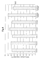
- Figure 1 is an upper view showing an end surface of a catalyst-supporting substrate.
- Figure 2 is a cross-sectional view in an axial direction of a filter catalyst.
- Figure 3 is a graph showing calculated results of a 50% purification temperature in HC purification by filter catalysts.
- Figure 4 is a graph showing calculated results of a 50% purification temperature in CO purification by filter catalysts.
- Figure 5 is a graph showing calculated results of a purification rate of particulates by filter catalysts.
- Figure 6 is a graph showing calculated results of an exhaust pressure of filter catalysts.
- Example of the present invention a filter catalyst was manufactured.
- a slurry A to be coated on a catalyst-supporting substrate 1 shown in Figure 1 was prepared.
- Figure 1 is an upper end surface of a catalyst-supporting substrate 1.
- alumina (Al 2 O 3 ) powder was put into a deionized water, and a solution was stirred so that the alumina powder was dispersed into the deionized water. Then, by subjecting the solution to a milling operation, the slurry A was prepared.
- the alumina dispersed into the slurry A has an average particle diameter of 0. 8 ⁇ m.
- FIG. 1 is an axial cross-sectional view of a filter catalyst 4.
- the honeycomb-shaped catalyst-supporting substrate 1 made of a cordierite has substantially circular tubular shape as a whole, and has an outer diameter of 129 mm, an axial length of 150 mm and 2 liters apparent volume, respectively.
- the catalyst-supporting substrate 1 has plural cells 2 and plural cells 3 which extend axially and which are demarcated by cellular wall 40 including plural tubular wall portions having thickness of 300 ⁇ m.
- the catalyst-supporting substrate 1 is provided with multiple continuous pores having an average pore diameter of 30 ⁇ m in the cellular wall 40, and a porosity of 60 % is established.
- One of two end openings formed at both axial ends of each cell is sealed by a sealing body 41 alternately. That is, about half of the plural cells are opened at one axial end surface, while rest of the plural cells are opened at other axial end surface.
- the sealed cells 2 and the opened cells 3 are alternately positioned to form a checkered pattern.
- the catalyst-supporting substrate 1 was weighed. It was confirmed that the alumina was loaded by a loaded amount of 75g, per 1 liter apparent volume of the catalyst-supporting substrate 1. Also confirmed was that the alumina loading layer was formed on the inside surface of pores of the whole cellular wall 40, in substantially uniform thickness.
- Alumina powder having an average particle diameter of 5 ⁇ m was put into a deionized water, and a solution was stirred so that the alumina powder is dispersed into the deionized water.
- the prepared slurry B was coated on the catalyst-supporting substrate 1 in which the alumina loading layer prepared by the slurry A was already formed.
- the catalyst-supporting substrate 1 was dipped into the slurry B in an area spreading from an upstream end (left end in Figure 2) to a 75 mm point away from the upstream end.
- an excessive slurry B was removed by blowing the air into the cells 2 and 3.
- the catalyst-supporting substrate 1 was dried and calcined to complete the coating.
- the slurry B was coated on the surface of the cellular wall 40 (more correctly, on inner surfaces of plural tubular wall portions) demarcating the cells 3 of which upstream openings are not sealed.
- the calcined catalyst-supporting substrate 1 was weighed.
- the alumina produced by the slurry B was loaded by a loading amount of 75 g, per the 1 liter apparent volume of the catalyst-supporting substrate 1. It is confirmed that the alumina loading layer was formed on the surface of the cellular wall 40 demarcating the cells 3 of which upstream openings are not sealed, in the area spreading from the upstream end to a 75 mm point away from the upstream end, in substantially uniform thickness.
- an aqueous solution containing Pt was prepared.
- the catalyst-supporting substrate 1 on which two kinds of the loading layers were formed was dipped into the aqueous solution, taken out from it, and then dried. When drying, the catalyst-supporting substrate 1 was heated at 350 °C for 1 hour. As a result, 2g of Pt was loaded on the alumina loading layers, per the 1 liter apparent volume of the catalyst-supporting substrate 1. Pt loaded on the loading layers uniformly, contributes as the catalytic component to burn the particulate contained in the exhaust gas.
- the filter catalyst 4 according to the Example 1 was manufactured.
- the second loading layer produced by the slurry A was formed on the catalyst-supporting substrate 1 made of the cordierite. That is, the second loading layer was formed on the inside surfaces of the multiple continuous pores in the cellular wall 40, by the loading amount of 75 g/L.
- the first loading layer produced by the slurry B is further formed on the surface in the area spreading from the upstream end to the 75 mm point away from the upstream end of the cellular wall 40, by the loading amount of 75 g/L. 2 g/L of Pt in total was loaded on the first loading layer and the second loading layer, to respectively form a first catalyst portion 5 and a second catalytic portion 6.
- the second catalytic portion 6 is covered by the first catalytic portion 5.
- the second catalytic portion 6 is exposed.
- the length of the area on which the first catalytic portion is formed was 1/2 of that of the cellular wall.
- a weight ratio between the first catalytic portion 5 and the second catalytic portion 6 was 1:1.
- the slurry A was prepared and was coated on the catalyst-supporting substrate in the same manner as the Example 1, to form the second loading layer.
- the slurry A was coated on the whole catalyst-supporting substrate. After drying of the slurry A, the catalyst-supporting substrate was weighed. As a result, loading of the alumina by loading amount of 100 g per the 1 liter apparent volume of the catalyst-supporting substrate was confirmed. Also confirmed was that the alumina loading layer produced by the slurry A was formed on the inside surface of the pores of the cellular wall in substantially uniform thickness, similar to the second catalytic portion of the Example 1.
- the slurry B was prepared and coated on the catalyst-supporting substrate in the same manner as the Example 1, to form the first loading layer.
- the slurry B was coated on the surface of the cellular wall, in an area spreading from the upstream end to a 50 mm point away from the upstream end. The openings of the cells formed by the upstream end of the cellular wall are not sealed.
- the catalyst-supporting substrate was weighed. As a result, loading of the alumina produced by the slurry B by loading amount of 50 g per the 1 liter apparent volume of the catalyst-supporting substrate was confirmed. Also confirmed was that the alumina loading layer was formed on the surface of the cellular wall in the area spreading from the upstream end to the 50 mm point away from the upstream end, in substantially uniform thickness. The openings of the cells formed by the upstream end of the cellular wall are not sealed.
- the filter catalyst of the Example 2 had same construction as that of the Example 1, except for the following points.
- the first exception is that the first loading layer was formed by the loading amount of 50 g/L, on the surface of the cellular wall in the area spreading from the upstream end to the 50 mm point away from the upstream end.
- the second exception is that the second loading layer was loaded by the loading amount of 100 g/L.
- the length of the area on which the first catalytic portion is formed was 1/3 of that of the cellular wall.
- the weight ratio of the first catalytic portion to the second catalytic portion was 1:2.
- the slurry A was prepared in the same manner as the Example 1, and was coated on the catalyst-supporting substrate in the area spreading from the downstream end to a 75 mm point away from the downstream end, to form the second loading layer. After drying of the slurry A, the catalyst-supporting substrate was weighed. As a result, loading of the alumina by loading amount of 75 g per the 1 liter apparent volume of the catalyst-supporting substrate was confirmed. Also confirmed was that the alumina loading layer produced by the slurry A was formed on the inside surface of the pores of the cellular wall in substantially uniform thickness, similar to the second catalytic portion of the Example 1.
- the slurry B was prepared and coated on the catalyst-supporting substrate in the same manner as the Example 1, to form the first loading layer.
- the slurry B was coated on the surface in the area spreading from the upstream end to a 75 mm point away from the upstream end of the cellular wall. The openings formed by the upstream end of the cellular wall are not sealed.
- the catalyst-supporting substrate was weighed. As a result, loading of the alumina produced by the slurry B by loading amount of 75 g per the 1 liter apparent volume of the catalyst-supporting substrate was confirmed. Also confirmed was that the alumina loading layer was formed on the surface in the area spreading from the upstream end to the 75 mm point away from the upstream end of the cellular wall, in substantially uniform thickness.
- the second loading layer produced by the slurry A was formed on the catalyst-supporting substrate. It was formed on the inside surfaces of the multiple continuous pores in the cellular wall, in the area spreading from the downstream end to the 75 mm point away from the downstream end, by the loading amount of 75 g/L.
- the first loading layer produced by the slurry B is further formed on the surface in the area spreading from the upstream end to the 75 mm point away from the upstream end of the cellular wall, by the loading amount of 75 g/L. 2 g/L of Pt in total was loaded on the first loading layer and the second loading layer, to respectively form a first catalyst portion and a second catalytic portion.
- the second catalytic portion is exposed.
- length of the upstream area on which the first catalyst portion is formed was 1/2 of that of the cellular wall.
- a weight ratio between the first catalytic portion and the second catalytic portion was 1: 1 .
- the slurry A was prepared in the same manner as the Example 1, and was coated on the catalyst-supporting substrate in the area spreading from the downstream end to a 120 mm point away from the downstream end, to form the second loading layer. After drying of the slurry A, the catalyst-supporting substrate was weighed. As a result, loading of the alumina by loading amount of 120 g per the 1 liter apparent volume of the catalyst-supporting substrate was confirmed. Also confirmed was that the alumina loading layer produced by the slurry A was formed on the inside surface of the pores of the cellular wall in substantially uniform thickness, similar to the second catalytic portion of the Example 1.
- the slurry B was prepared and coated on the catalyst-supporting substrate in the same manner as the Example 1, to form the first loading layer.
- the slurry B was coated on the surface in the area spreading from the upstream end to a 30 mm point away from the upstream end of the cellular wall. The openings formed by the upstream end of the cellular wall are not sealed.
- the catalyst-supporting substrate was weighed. As a result, loading of the alumina produced by the slurry B by loading amount of 30 g per the 1 liter apparent volume of the catalyst-supporting substrate was confirmed. Also confirmed was that the alumina loading layer produced by the slurry B was formed on the surface in the area spreading from the upstream end to the 30 mm point away from the upstream end of the cellular wall, in substantially uniform thickness.
- the filter catalyst of the Example 4 had same construction as that of the Example 3, except for the following points.
- the first exception is that the first loading layer was formed by the loading amount of 30 g/L, on the surface in the area spreading from the upstream end to the 30 mm point away from the upstream end of the cellular wall.
- the second exception is that the second loading layer was loaded by the loading amount of 120 g/L, in the area spreading from the downstream end to the 120 mm point away from the downstream end of the cellular wall.
- the length of the area on which the first catalytic portion is formed was 1/5 of that of the cellular wall.
- the weight ratio of the first catalytic portion to the second catalytic portion was 1:4.
- the slurry A was prepared in the same manner as the Example 1, and was coated on the catalyst-supporting substrate in the area spreading from the downstream end to a 60 mm point away from the downstream end, to form the second loading layer. After drying of the slurry A, the catalyst-supporting substrate was weighed. As a result, loading of the alumina produced by the slurry A by loading amount of 60g per the 1 liter apparent volume of the catalyst-supporting substrate was confirmed. Also confirmed was that the alumina loading layer produced by the slurry A was formed on the inside surface of the pores of the cellular wall in substantially uniform thickness, similar to the second catalytic portion of the Example 1.
- the slurry B was prepared and coated on the catalyst-supporting substrate in the same manner as the Example 1, to form the first loading layer.
- the slurry B was coated in the area spreading from the upstream end to the 90 mm point away from the upstream end of the cellular wall. The openings formed by the upstream end of the cellular wall are not sealed.
- the catalyst-supporting substrate was weighed. As a result, loading of the alumina produced by the slurry B by loading amount of 90 g per the 1 liter apparent volume of the catalyst-supporting substrate was confirmed. Also confirmed was that the alumina loading layer produced by the slurry B was formed on the surface in the area spreading from the upstream end to the 90 mm point away from the upstream end of the cellular wall, in substantially uniform thickness.
- the filter catalyst of the Example 5 had same construction as that of the Example 3, except for the following points.
- the first exception is that the first loading layer was formed by the loading amount of 90 g/L, on the surface in the area spreading from the upstream end to the 90 mm point away from the upstream end of the cellular wall.
- the second exception is that the second loading layer was loaded by the loading amount of 60 g/L, in the area spreading from the downstream end to the 60 mm point away from the downstream end of the cellular wall.
- the length of the area on which the first catalytic portion is formed was 3/5 of that of the cellular wall.
- the weight ratio of the first catalytic portion to the second catalytic portion was 3:2.
- the slurry A was prepared by the same manner as the Example 1.
- the prepared slurry A was coated on the catalyst-supporting substrate which is same as that of the Example 1.
- the whole catalyst-supporting substrate was dipped into the slurry A, and taken out from it. After taking out the catalyst-supporting substrate, the air was blown into the cells of it to remove the excessive slurry A. Then, the catalyst-supporting substrate was dried and calcined.
- the catalyst-supporting substrate was weighed. It was confirmed that the alumina was loaded on the catalyst-supporting substrate by the loading amount of 150 g per the 1 liter apparent volume of the catalyst-supporting substrate. Also confirmed was the alumina loading layer produced by the slurry A was formed on the inside surface of the pores of the cellular wall, in substantially uniform thickness. Noted that the slurry B was not prepared and therefore was not coated on the catalyst-supporting substrate.
- the filter catalyst of the Comparative Example 1 was manufactured.
- the loading layer produced by the slurry A was formed on the inside surface of the pores in the cellular wall, by the loading amount of 150 g/L.
- Pt was loaded by the loading amount of 2 g/L.
- the slurry B was prepared by the same manner as the Example 1.
- the prepared slurry B was coated on the catalyst-supporting substrate which is same as that of the Example 1.
- the whole catalyst-supporting substrate was dipped into the slurry B, and taken out from it. After taking out the catalyst-supporting substrate, the air was blown into the cells of it to remove the excessive slurry B. Then, the catalyst-supporting substrate was dried and calcined.
- the catalyst-supporting substrate was weighed. It was confirmed that the alumina was loaded on the catalyst-supporting substrate by the loading amount of 150 g per the 1 liter apparent volume of the catalyst-supporting substrate. Also confirmed was the alumina loading layer produced by the slurry B was dispersed on the surface of the cellular wall, in substantially uniform thickness. Noted that the slurry A was not prepared and therefore was not coated on the catalyst-supporting substrate.
- the filter catalyst of the Comparative Example 2 was manufactured.
- the loading layer produced by the slurry B was formed on the surface of the cellular wall, by the loading amount of 150 g/L.
- Pt was loaded by the loading amount of 2 g/L.
- the filter catalysts of the Examples 1 to 5 and that of the Comparative Examples 1 and 2 were put into place in an exhaust system of a vehicle.
- This vehicle has a direct-injection and a supercharge type diesel engine which has 2 liters of displacement volume. With the revolution speed of 2000 rpm, torque was varied and catalyst temperature of the filter catalysts was raised from 150°C up to 450°C
- Concentration of HC and concentration of CO in the exhaust gas in front of (upstream) the filter catalysts, and that at rear of (downstream) the filter catalysts were measured. Based on the measured concentrations of the exhaust gas which was not purified by the filter catalysts, and that which was purified by the filter catalysts, the purification rate of the exhaust gas was calculated, by using the following equation 1. Temperature of the filter catalysts when the purification rate reached 50 % was measured to be used as a catalytic activity of the filter catalysts.
- each of the filter catalysts of the Examples 1 to 5 apparently has higher catalytic activity, that is, it has the lower CO-50% purification temperature and the lower HC-50% purification temperature than that of the Comparative Example 1.
- the catalytic portion was not formed on the surface of the cellular wall but was formed on the inside surface of the pores in the cellular wall.
- the filter catalysts of the Examples 1 to 5 and that of the Comparative Examples 1 to 2 were put into place in exhaust system of a vehicle.
- This vehicle has a direct-injection type diesel engine which has 2.8 liters of displacement volume.
- pressure sensors were arranged in the exhaust system, in front of (upstream) and at rear of (downstream) of the filter catalyst.
- the diesel engine was operated by EC mode, and the particulates contained in the exhaust gas which passed through the filter catalyst were captured. Weight of the captured particulates was measured as the sum of a soluble component (SOF) and a soot.
- SOF soluble component
- wbp is an abbreviation of weight before purification
- wap is an abbreviation of weight after purification, respectively.
- each of the filter catalysts of the Examples 1 to 5 has the particulate purification rate which is higher than that of the Comparative Example 2, in which the catalytic portion was formed on the surface of the cellular wall. Judging from it, it is guessed that the second catalytic portion of the Example 1 to 5 formed on the inside surface of the pores functioned effectively, for purifying the particulates.
- each of the filter catalysts of the Examples 1 to 5 has the exhaust pressure which is lower than that of the Comparative Example 2, in which the catalytic portion was formed on the surface of the cellular wall. Judging from it, it is guessed that the second catalytic portion formed on the inside surface of the pores of the Examples 1 to 5 suppressed rise of the pressure loss effectively.
- the filter catalysts of the Examples 1 to 5 are excellent in purifying ability of the purified component, including the gaseous purified component of HC and CO, and granular purified component of the particulates. Also confirmed was that the filter catalysts of the Examples 1 to 5 are excellent in suppressing rise of the pressure loss.
- a filter catalyst of the present invention is comprised of a catalyst-supporting substrate 1, and catalytic portions 5, 6 for purifying an exhaust gas.
- the catalytic portions includes the first catalytic portion 5 for purifying HC, CO and NOx, and the second catalytic portion 6 for purifying the particulates.
- the first catalytic portion 5 is formed on a surface of at least a portion of the cellular wall 40, and the second catalytic portion 6 is formed on an inside surface of the pores.
Landscapes
- Chemical & Material Sciences (AREA)
- Engineering & Computer Science (AREA)
- Chemical Kinetics & Catalysis (AREA)
- Combustion & Propulsion (AREA)
- Materials Engineering (AREA)
- Organic Chemistry (AREA)
- Mechanical Engineering (AREA)
- General Engineering & Computer Science (AREA)
- Health & Medical Sciences (AREA)
- Biomedical Technology (AREA)
- Environmental & Geological Engineering (AREA)
- Analytical Chemistry (AREA)
- General Chemical & Material Sciences (AREA)
- Oil, Petroleum & Natural Gas (AREA)
- Catalysts (AREA)
- Exhaust Gas Treatment By Means Of Catalyst (AREA)
- Processes For Solid Components From Exhaust (AREA)
- Filtering Materials (AREA)
- Exhaust Gas After Treatment (AREA)
Applications Claiming Priority (1)
| Application Number | Priority Date | Filing Date | Title |
|---|---|---|---|
| JP2004327697A JP4907860B2 (ja) | 2004-11-11 | 2004-11-11 | フィルタ触媒 |
Publications (3)
| Publication Number | Publication Date |
|---|---|
| EP1657410A2 true EP1657410A2 (fr) | 2006-05-17 |
| EP1657410A3 EP1657410A3 (fr) | 2006-08-16 |
| EP1657410B1 EP1657410B1 (fr) | 2013-10-23 |
Family
ID=35782483
Family Applications (1)
| Application Number | Title | Priority Date | Filing Date |
|---|---|---|---|
| EP05024295.7A Active EP1657410B1 (fr) | 2004-11-11 | 2005-11-08 | Filtre catalytique |
Country Status (3)
| Country | Link |
|---|---|
| US (1) | US7781371B2 (fr) |
| EP (1) | EP1657410B1 (fr) |
| JP (1) | JP4907860B2 (fr) |
Cited By (23)
| Publication number | Priority date | Publication date | Assignee | Title |
|---|---|---|---|---|
| WO2008011146A1 (fr) * | 2006-07-21 | 2008-01-24 | Dow Global Technologies Inc. | Filtre à suies perfectionné à zone catalysée |
| GB2481057A (en) * | 2010-06-11 | 2011-12-14 | Johnson Matthey Plc | Exhaust system comprising a catalyst with a downstream filter and SCR catalyst |
| EP2435673A2 (fr) * | 2009-05-29 | 2012-04-04 | Corning Inc. | Filtre de particules avec un revêtement faiblement chargé en suie |
| EP2491999A1 (fr) * | 2011-02-22 | 2012-08-29 | Honda Motor Co., Ltd. | Filtre de purification d'échappement |
| EP2539040A1 (fr) * | 2010-02-23 | 2013-01-02 | Basf Se | Filtre à suie catalytique amélioré |
| GB2497440A (en) * | 2009-02-26 | 2013-06-12 | Johnson Matthey Plc | Filtering particulate matter from exhaust gas |
| US8919110B2 (en) | 2009-02-26 | 2014-12-30 | Johnson Matthey Public Limited Company | Method and system using a filter for treating exhaust gas having particulate matter |
| FR3020091A1 (fr) * | 2014-04-22 | 2015-10-23 | Peugeot Citroen Automobiles Sa | Filtre a particules |
| US9352277B2 (en) | 2010-06-02 | 2016-05-31 | Johnson Matthey Plc | Diesel particulate filter |
| WO2017170669A1 (fr) * | 2016-04-01 | 2017-10-05 | Johnson Matthey Japan G.K. | Filtre de purification de gaz d'échappement |
| WO2018172299A1 (fr) | 2017-03-23 | 2018-09-27 | Umicore Ag & Co. Kg | Filtre à particules à activité catalytique |
| DE202017007046U1 (de) | 2017-12-19 | 2019-04-29 | Umicore Ag & Co. Kg | Katalytisch aktives Partikelfilter |
| DE202017007047U1 (de) | 2017-12-19 | 2019-04-29 | Umicore Ag & Co. Kg | Katalytisch aktives Partikelfilter |
| EP3501647A1 (fr) | 2017-12-19 | 2019-06-26 | Umicore Ag & Co. Kg | Filtre à particules catalityquement actif |
| EP3501646A1 (fr) | 2017-12-19 | 2019-06-26 | Umicore Ag & Co. Kg | Filtre à particules catalityquement actif |
| EP3501648A1 (fr) | 2017-12-19 | 2019-06-26 | Umicore Ag & Co. Kg | Filtre à particules catalityquement actif |
| EP3581271A4 (fr) * | 2017-03-23 | 2020-01-22 | Cataler Corporation | Catalyseur de purification de gaz d'échappement |
| WO2020200394A1 (fr) | 2019-03-29 | 2020-10-08 | Umicore Ag & Co. Kg | Filtre à particules à activité catalytique |
| WO2020200397A1 (fr) | 2019-03-29 | 2020-10-08 | Umicore Ag & Co. Kg | Filtre à particules à activité catalytique |
| WO2020200398A1 (fr) | 2019-03-29 | 2020-10-08 | Umicore Ag & Co. Kg | Filtre à particules à activité catalytique |
| WO2023001865A1 (fr) | 2021-07-21 | 2023-01-26 | Umicore Ag & Co. Kg | Système de purification de gaz d'échappement pour purifier des gaz d'échappement de moteurs à essence |
| DE102021118802A1 (de) | 2021-07-21 | 2023-01-26 | Umicore Ag & Co. Kg | Abgasreinigungssystem zur Reinigung von Abgasen von Benzinmotoren |
| WO2023001617A1 (fr) | 2021-07-21 | 2023-01-26 | Umicore Ag & Co. Kg | Système d'épuration des gaz d'échappement pour épurer les gaz d'échappement de moteurs à combustion interne |
Families Citing this family (16)
| Publication number | Priority date | Publication date | Assignee | Title |
|---|---|---|---|---|
| JP5260982B2 (ja) * | 2007-03-30 | 2013-08-14 | イビデン株式会社 | ハニカムフィルタ |
| DE102007046158B4 (de) * | 2007-09-27 | 2014-02-13 | Umicore Ag & Co. Kg | Verwendung eines katalytisch aktiven Partikelfilters zur Entfernung von Partikeln aus dem Abgas von mit überwiegend stöchiometrischem Luft/Kraftstoff-Gemisch betriebenen Verbrennungsmotoren |
| JP5258426B2 (ja) * | 2008-07-14 | 2013-08-07 | Udトラックス株式会社 | エンジンの排気浄化装置 |
| JP2011056393A (ja) * | 2009-09-09 | 2011-03-24 | Mitsubishi Motors Corp | 排ガス浄化装置 |
| JP6023395B2 (ja) * | 2009-10-06 | 2016-11-09 | 日本碍子株式会社 | 触媒担持フィルタ |
| JP5517879B2 (ja) * | 2010-10-18 | 2014-06-11 | 三菱重工業株式会社 | ディーゼルエンジンのpm排出量推定装置及びpm排出量制御装置 |
| GB2497597A (en) | 2011-12-12 | 2013-06-19 | Johnson Matthey Plc | A Catalysed Substrate Monolith with Two Wash-Coats |
| WO2014178633A1 (fr) * | 2013-05-02 | 2014-11-06 | 희성촉매 주식회사 | Filtre à particules d'essence pour moteur à injection directe d'essence |
| WO2014178632A1 (fr) * | 2013-05-02 | 2014-11-06 | 희성촉매 주식회사 | Système de catalyseur de purification des gaz d'échappement d'un moteur à essence |
| JP6315194B2 (ja) * | 2014-06-19 | 2018-04-25 | 株式会社豊田中央研究所 | 排ガス浄化用触媒、その製造方法、及び、それを用いた排ガス浄化方法 |
| JP6458827B2 (ja) | 2017-06-05 | 2019-01-30 | マツダ株式会社 | エンジンの排気ガス処理装置 |
| US11266982B2 (en) | 2018-03-30 | 2022-03-08 | Mitsui Mining & Smelting Co., Ltd. | Exhaust gas purification catalyst |
| JP7120959B2 (ja) * | 2019-04-22 | 2022-08-17 | トヨタ自動車株式会社 | 構造体 |
| JP7211893B2 (ja) | 2019-05-24 | 2023-01-24 | トヨタ自動車株式会社 | 排ガス浄化装置 |
| JP7381372B2 (ja) | 2020-03-12 | 2023-11-15 | トヨタ自動車株式会社 | 排ガス浄化装置 |
| JP2022186014A (ja) * | 2021-06-04 | 2022-12-15 | トヨタ自動車株式会社 | 排ガス浄化装置 |
Citations (3)
| Publication number | Priority date | Publication date | Assignee | Title |
|---|---|---|---|---|
| JPH09173866A (ja) | 1995-12-28 | 1997-07-08 | Nippon Soken Inc | ディーゼル排ガス浄化フィルタ |
| JP2002295228A (ja) | 2001-03-30 | 2002-10-09 | Ibiden Co Ltd | 排気ガス浄化フィルタ |
| EP1398081A1 (fr) | 2002-09-13 | 2004-03-17 | Toyota Jidosha Kabushiki Kaisha | Filtre catalytique d'épuration de gaz d'échappement Diesel et procédé de fabrication |
Family Cites Families (8)
| Publication number | Priority date | Publication date | Assignee | Title |
|---|---|---|---|---|
| EP0731256B1 (fr) | 1992-09-28 | 2000-03-22 | Ford Motor Company Limited | Elément filtrant pour la commande d'émission des gaz d'échappement des moteurs à combustion interne |
| JP3575139B2 (ja) * | 1995-11-07 | 2004-10-13 | 日産自動車株式会社 | ディーゼルエンジン用酸化触媒 |
| US6133185A (en) | 1995-11-09 | 2000-10-17 | Toyota Jidosha Kabushiki Kaisha | Exhaust gas purifying catalyst |
| KR100319922B1 (ko) * | 1999-03-05 | 2002-01-09 | 이형도 | 디젤엔진 배기가스 정화용 촉매 |
| JP4393039B2 (ja) * | 2001-07-18 | 2010-01-06 | イビデン株式会社 | 触媒つきフィルタ、その製造方法及び排気ガス浄化システム |
| JP3872354B2 (ja) * | 2002-02-06 | 2007-01-24 | トヨタ自動車株式会社 | ディーゼル排ガス浄化用フィルタ型触媒 |
| JP2003251201A (ja) * | 2002-02-28 | 2003-09-09 | Toyota Central Res & Dev Lab Inc | 多孔質コート層の形成方法 |
| JP2003278526A (ja) * | 2002-03-25 | 2003-10-02 | Nissan Motor Co Ltd | 排気微粒子捕集用フィルタ |
-
2004
- 2004-11-11 JP JP2004327697A patent/JP4907860B2/ja active Active
-
2005
- 2005-11-07 US US11/267,280 patent/US7781371B2/en active Active
- 2005-11-08 EP EP05024295.7A patent/EP1657410B1/fr active Active
Patent Citations (3)
| Publication number | Priority date | Publication date | Assignee | Title |
|---|---|---|---|---|
| JPH09173866A (ja) | 1995-12-28 | 1997-07-08 | Nippon Soken Inc | ディーゼル排ガス浄化フィルタ |
| JP2002295228A (ja) | 2001-03-30 | 2002-10-09 | Ibiden Co Ltd | 排気ガス浄化フィルタ |
| EP1398081A1 (fr) | 2002-09-13 | 2004-03-17 | Toyota Jidosha Kabushiki Kaisha | Filtre catalytique d'épuration de gaz d'échappement Diesel et procédé de fabrication |
Cited By (50)
| Publication number | Priority date | Publication date | Assignee | Title |
|---|---|---|---|---|
| WO2008011146A1 (fr) * | 2006-07-21 | 2008-01-24 | Dow Global Technologies Inc. | Filtre à suies perfectionné à zone catalysée |
| US7772151B2 (en) | 2006-07-21 | 2010-08-10 | Dow Global Technologies Inc. | Zone catalyzed soot filter |
| US8919110B2 (en) | 2009-02-26 | 2014-12-30 | Johnson Matthey Public Limited Company | Method and system using a filter for treating exhaust gas having particulate matter |
| GB2497440A (en) * | 2009-02-26 | 2013-06-12 | Johnson Matthey Plc | Filtering particulate matter from exhaust gas |
| GB2497440B (en) * | 2009-02-26 | 2013-12-11 | Johnson Matthey Plc | Filter including lean NOx catalyst for positive ignition engine |
| EP2589427A3 (fr) * | 2009-02-26 | 2014-08-27 | Johnson Matthey Public Limited Company | Filtre pour filtrer la matière particulaire de gaz d'échappement émis par un moteur à allumage commandé |
| EP2435673B1 (fr) * | 2009-05-29 | 2022-08-03 | Corning Inc. | Filtre de particules avec un revêtement faiblement chargé en suie |
| EP2435673A2 (fr) * | 2009-05-29 | 2012-04-04 | Corning Inc. | Filtre de particules avec un revêtement faiblement chargé en suie |
| EP4119224A1 (fr) * | 2009-05-29 | 2023-01-18 | Corning Incorporated | Filtre de particules ayant un revêtement faiblement chargé en suie |
| US8858904B2 (en) | 2010-02-23 | 2014-10-14 | Basf Corporation | Catalyzed soot filter |
| EP2539040A4 (fr) * | 2010-02-23 | 2014-09-03 | Basf Se | Filtre à suie catalytique amélioré |
| EP2539040A1 (fr) * | 2010-02-23 | 2013-01-02 | Basf Se | Filtre à suie catalytique amélioré |
| US9352277B2 (en) | 2010-06-02 | 2016-05-31 | Johnson Matthey Plc | Diesel particulate filter |
| GB2481057A (en) * | 2010-06-11 | 2011-12-14 | Johnson Matthey Plc | Exhaust system comprising a catalyst with a downstream filter and SCR catalyst |
| EP2491999A1 (fr) * | 2011-02-22 | 2012-08-29 | Honda Motor Co., Ltd. | Filtre de purification d'échappement |
| FR3020091A1 (fr) * | 2014-04-22 | 2015-10-23 | Peugeot Citroen Automobiles Sa | Filtre a particules |
| WO2017170669A1 (fr) * | 2016-04-01 | 2017-10-05 | Johnson Matthey Japan G.K. | Filtre de purification de gaz d'échappement |
| US10233803B2 (en) | 2016-04-01 | 2019-03-19 | Johnson Matthey Public Limited Company | Exhaust gas purification filter |
| WO2018172299A1 (fr) | 2017-03-23 | 2018-09-27 | Umicore Ag & Co. Kg | Filtre à particules à activité catalytique |
| US11400414B2 (en) | 2017-03-23 | 2022-08-02 | Umicore Ag & Co. Kg | Catalytically active particulate filter |
| US10933373B2 (en) | 2017-03-23 | 2021-03-02 | Umicore Ag & Co. Kg | Catalytically active particulate filter |
| EP3581271A4 (fr) * | 2017-03-23 | 2020-01-22 | Cataler Corporation | Catalyseur de purification de gaz d'échappement |
| WO2019121367A1 (fr) | 2017-12-19 | 2019-06-27 | Umicore Ag & Co. Kg | Filtre à particules à activité catalytique |
| US11702971B2 (en) | 2017-12-19 | 2023-07-18 | Umicore Ag & Co. Kg | Catalytically active particulate filter |
| WO2019121372A1 (fr) | 2017-12-19 | 2019-06-27 | Umicore Ag & Co. Kg | Filtre à particules à activité catalytique |
| WO2019121365A1 (fr) | 2017-12-19 | 2019-06-27 | Umicore Ag & Co. Kg | Filtre à particules à activité catalytique |
| EP3505246A1 (fr) | 2017-12-19 | 2019-07-03 | Umicore Ag & Co. Kg | Filtre à particules à effet catalityque actif |
| EP3505245A1 (fr) | 2017-12-19 | 2019-07-03 | Umicore Ag & Co. Kg | Filtre à particules à effet catalytique actif |
| EP3501648A1 (fr) | 2017-12-19 | 2019-06-26 | Umicore Ag & Co. Kg | Filtre à particules catalityquement actif |
| WO2019121375A1 (fr) | 2017-12-19 | 2019-06-27 | Umicore Ag & Co. Kg | Filtre à particules à activité catalytique |
| EP4365421A2 (fr) | 2017-12-19 | 2024-05-08 | Umicore AG & Co. KG | Filtre à particules à activité catalytique |
| US11623179B2 (en) | 2017-12-19 | 2023-04-11 | Umicore Ag & Co. Kg | Catalytically active particulate filter |
| EP3501646A1 (fr) | 2017-12-19 | 2019-06-26 | Umicore Ag & Co. Kg | Filtre à particules catalityquement actif |
| US11179676B2 (en) | 2017-12-19 | 2021-11-23 | Umicore Ag & Co. Kg | Catalytically active particulate filter |
| US11185820B2 (en) | 2017-12-19 | 2021-11-30 | Umicore Ag & Co. Kg | Multi-layer three-way catalytic converter |
| US11291952B2 (en) | 2017-12-19 | 2022-04-05 | Umicore Ag & Co. Kg | Single-layer 3-way catalytic converter |
| US11628400B2 (en) | 2017-12-19 | 2023-04-18 | Umicore Ag & Co. Kg | Catalytically active particulate filter |
| EP3501647A1 (fr) | 2017-12-19 | 2019-06-26 | Umicore Ag & Co. Kg | Filtre à particules catalityquement actif |
| DE202017007047U1 (de) | 2017-12-19 | 2019-04-29 | Umicore Ag & Co. Kg | Katalytisch aktives Partikelfilter |
| DE202017007046U1 (de) | 2017-12-19 | 2019-04-29 | Umicore Ag & Co. Kg | Katalytisch aktives Partikelfilter |
| WO2020200394A1 (fr) | 2019-03-29 | 2020-10-08 | Umicore Ag & Co. Kg | Filtre à particules à activité catalytique |
| EP4029592A1 (fr) | 2019-03-29 | 2022-07-20 | UMICORE AG & Co. KG | Filtre à particules à activité catalytique |
| WO2020200398A1 (fr) | 2019-03-29 | 2020-10-08 | Umicore Ag & Co. Kg | Filtre à particules à activité catalytique |
| WO2020200397A1 (fr) | 2019-03-29 | 2020-10-08 | Umicore Ag & Co. Kg | Filtre à particules à activité catalytique |
| DE102021118802A1 (de) | 2021-07-21 | 2023-01-26 | Umicore Ag & Co. Kg | Abgasreinigungssystem zur Reinigung von Abgasen von Benzinmotoren |
| WO2023001863A1 (fr) | 2021-07-21 | 2023-01-26 | Umicore Ag & Co. Kg | Système de gaz d'échappement permettant de purifier des gaz d'échappement d'un moteur à essence |
| WO2023001617A1 (fr) | 2021-07-21 | 2023-01-26 | Umicore Ag & Co. Kg | Système d'épuration des gaz d'échappement pour épurer les gaz d'échappement de moteurs à combustion interne |
| DE102021118803A1 (de) | 2021-07-21 | 2023-01-26 | Umicore Ag & Co. Kg | Abgasreinigungssystem zur Reinigung von Abgasen von Benzinmotoren |
| DE102021118801A1 (de) | 2021-07-21 | 2023-01-26 | Umicore Ag & Co. Kg | Abgasreinigungssystem zur Reinigung von Abgasen von Benzinmotoren |
| WO2023001865A1 (fr) | 2021-07-21 | 2023-01-26 | Umicore Ag & Co. Kg | Système de purification de gaz d'échappement pour purifier des gaz d'échappement de moteurs à essence |
Also Published As
| Publication number | Publication date |
|---|---|
| US20060100101A1 (en) | 2006-05-11 |
| US7781371B2 (en) | 2010-08-24 |
| JP4907860B2 (ja) | 2012-04-04 |
| EP1657410A3 (fr) | 2006-08-16 |
| JP2006136784A (ja) | 2006-06-01 |
| EP1657410B1 (fr) | 2013-10-23 |
Similar Documents
| Publication | Publication Date | Title |
|---|---|---|
| EP1657410B1 (fr) | Filtre catalytique | |
| EP1837494B1 (fr) | Système de purification de gaz d'échappement | |
| EP1679119B1 (fr) | Procédé de fabrication d'un filtre catalyseur pour la purification de gaz d'échappement d'un moteur diesel | |
| EP1839748B1 (fr) | Corps catalytique en nid d'abeille | |
| EP2276555B1 (fr) | Catalyseur de purification de gaz d'échappement et son procédé de fabrication | |
| US7306771B2 (en) | Filter catalyst for purifying exhaust gases and its manufacturing method thereof | |
| EP2324904B1 (fr) | Filtre de support de catalyseur et système de purification de gaz d'échappement | |
| EP1437491B1 (fr) | Filtre catalyseur pour la purification de gaz d'échappement | |
| EP2382031B1 (fr) | Systèmes et procédés de traitement d'émissions employant un filtre rcs catalysé et un catalyseur rcs aval | |
| KR100692356B1 (ko) | 벌집형 구조체 | |
| EP1952884B1 (fr) | Catalyseur d epuration des gaz d echappement | |
| EP1371826A2 (fr) | Filtre catalytique pour la purification des gaz d'échappement | |
| US7517830B2 (en) | Substrate for exhaust-gas purifying filter catalyst | |
| US20010038810A1 (en) | Catalytic devices and method of making said devices | |
| EP1723998B1 (fr) | Catalyseur filtre | |
| EP1710009A1 (fr) | Catalyseur pour purifier de gaz d'échappement d' un moteur diesel | |
| EP1949959A1 (fr) | Appareil d'epuration des gaz d'echappement | |
| EP1961482A1 (fr) | Support de catalyseur | |
| US10408102B2 (en) | Oxidation catalyst device for exhaust gas purification | |
| EP2747878B1 (fr) | Procédé pour la préparation d'un catalyseur d'oxydation et d'un système de post-traitement d'un gaz d'échappement | |
| JP2008151100A (ja) | 排ガス浄化装置 | |
| US20030086835A1 (en) | Catalyst for automobile | |
| EP2177264B1 (fr) | Filtre à particules pour la purification de gaz d'échappement comprenant un catalyseur de purification de gaz d'échappement et son procédé de fabrication | |
| JP2006159020A (ja) | 排ガス浄化フィルタ及び排ガス浄化触媒 | |
| US10661216B2 (en) | Soot particle filter with storage cells for a catalyst |
Legal Events
| Date | Code | Title | Description |
|---|---|---|---|
| PUAI | Public reference made under article 153(3) epc to a published international application that has entered the european phase |
Free format text: ORIGINAL CODE: 0009012 |
|
| 17P | Request for examination filed |
Effective date: 20051108 |
|
| AK | Designated contracting states |
Kind code of ref document: A2 Designated state(s): AT BE BG CH CY CZ DE DK EE ES FI FR GB GR HU IE IS IT LI LT LU LV MC NL PL PT RO SE SI SK TR |
|
| AX | Request for extension of the european patent |
Extension state: AL BA HR MK YU |
|
| PUAL | Search report despatched |
Free format text: ORIGINAL CODE: 0009013 |
|
| AK | Designated contracting states |
Kind code of ref document: A3 Designated state(s): AT BE BG CH CY CZ DE DK EE ES FI FR GB GR HU IE IS IT LI LT LU LV MC NL PL PT RO SE SI SK TR |
|
| AX | Request for extension of the european patent |
Extension state: AL BA HR MK YU |
|
| AKX | Designation fees paid |
Designated state(s): DE FR GB |
|
| 17Q | First examination report despatched |
Effective date: 20100723 |
|
| GRAP | Despatch of communication of intention to grant a patent |
Free format text: ORIGINAL CODE: EPIDOSNIGR1 |
|
| RIC1 | Information provided on ipc code assigned before grant |
Ipc: B01D 53/94 20060101ALI20130225BHEP Ipc: F01N 3/035 20060101AFI20130225BHEP Ipc: B01J 23/42 20060101ALI20130225BHEP Ipc: B01J 37/02 20060101ALI20130225BHEP |
|
| RIN1 | Information on inventor provided before grant (corrected) |
Inventor name: AONO, NORIHIKO Inventor name: TSUJI, MAKOTO Inventor name: OKI, DAISUKE |
|
| GRAP | Despatch of communication of intention to grant a patent |
Free format text: ORIGINAL CODE: EPIDOSNIGR1 |
|
| INTG | Intention to grant announced |
Effective date: 20130508 |
|
| GRAS | Grant fee paid |
Free format text: ORIGINAL CODE: EPIDOSNIGR3 |
|
| GRAA | (expected) grant |
Free format text: ORIGINAL CODE: 0009210 |
|
| AK | Designated contracting states |
Kind code of ref document: B1 Designated state(s): DE FR GB |
|
| REG | Reference to a national code |
Ref country code: GB Ref legal event code: FG4D |
|
| REG | Reference to a national code |
Ref country code: DE Ref legal event code: R096 Ref document number: 602005041578 Country of ref document: DE Effective date: 20131219 |
|
| REG | Reference to a national code |
Ref country code: DE Ref legal event code: R097 Ref document number: 602005041578 Country of ref document: DE |
|
| PLBE | No opposition filed within time limit |
Free format text: ORIGINAL CODE: 0009261 |
|
| STAA | Information on the status of an ep patent application or granted ep patent |
Free format text: STATUS: NO OPPOSITION FILED WITHIN TIME LIMIT |
|
| 26N | No opposition filed |
Effective date: 20140724 |
|
| REG | Reference to a national code |
Ref country code: DE Ref legal event code: R097 Ref document number: 602005041578 Country of ref document: DE Effective date: 20140724 |
|
| REG | Reference to a national code |
Ref country code: FR Ref legal event code: PLFP Year of fee payment: 11 |
|
| REG | Reference to a national code |
Ref country code: FR Ref legal event code: PLFP Year of fee payment: 12 |
|
| REG | Reference to a national code |
Ref country code: FR Ref legal event code: PLFP Year of fee payment: 13 |
|
| PGFP | Annual fee paid to national office [announced via postgrant information from national office to epo] |
Ref country code: GB Payment date: 20231123 Year of fee payment: 19 |
|
| PGFP | Annual fee paid to national office [announced via postgrant information from national office to epo] |
Ref country code: FR Payment date: 20231120 Year of fee payment: 19 Ref country code: DE Payment date: 20231121 Year of fee payment: 19 |