EP1657210B2 - Crane with fibre cable - Google Patents
Crane with fibre cable Download PDFInfo
- Publication number
- EP1657210B2 EP1657210B2 EP05021048.3A EP05021048A EP1657210B2 EP 1657210 B2 EP1657210 B2 EP 1657210B2 EP 05021048 A EP05021048 A EP 05021048A EP 1657210 B2 EP1657210 B2 EP 1657210B2
- Authority
- EP
- European Patent Office
- Prior art keywords
- rope
- crane
- drive
- accordance
- ropes
- Prior art date
- Legal status (The legal status is an assumption and is not a legal conclusion. Google has not performed a legal analysis and makes no representation as to the accuracy of the status listed.)
- Active
Links
- 239000000835 fiber Substances 0.000 title claims abstract description 12
- 239000004760 aramid Substances 0.000 claims description 13
- 229920003235 aromatic polyamide Polymers 0.000 claims description 12
- 238000004804 winding Methods 0.000 claims description 12
- 238000004873 anchoring Methods 0.000 abstract 1
- 229910000831 Steel Inorganic materials 0.000 description 19
- 239000010959 steel Substances 0.000 description 19
- 239000010410 layer Substances 0.000 description 4
- 230000000694 effects Effects 0.000 description 2
- 238000009434 installation Methods 0.000 description 2
- 239000002356 single layer Substances 0.000 description 2
- 238000005303 weighing Methods 0.000 description 2
- 229920006231 aramid fiber Polymers 0.000 description 1
- 238000010276 construction Methods 0.000 description 1
- 238000001514 detection method Methods 0.000 description 1
- 239000000463 material Substances 0.000 description 1
- 230000008092 positive effect Effects 0.000 description 1
- 238000010008 shearing Methods 0.000 description 1
Images


Classifications
-
- B—PERFORMING OPERATIONS; TRANSPORTING
- B66—HOISTING; LIFTING; HAULING
- B66C—CRANES; LOAD-ENGAGING ELEMENTS OR DEVICES FOR CRANES, CAPSTANS, WINCHES, OR TACKLES
- B66C23/00—Cranes comprising essentially a beam, boom, or triangular structure acting as a cantilever and mounted for translatory of swinging movements in vertical or horizontal planes or a combination of such movements, e.g. jib-cranes, derricks, tower cranes
- B66C23/18—Cranes comprising essentially a beam, boom, or triangular structure acting as a cantilever and mounted for translatory of swinging movements in vertical or horizontal planes or a combination of such movements, e.g. jib-cranes, derricks, tower cranes specially adapted for use in particular purposes
- B66C23/26—Cranes comprising essentially a beam, boom, or triangular structure acting as a cantilever and mounted for translatory of swinging movements in vertical or horizontal planes or a combination of such movements, e.g. jib-cranes, derricks, tower cranes specially adapted for use in particular purposes for use on building sites; constructed, e.g. with separable parts, to facilitate rapid assembly or dismantling, for operation at successively higher levels, for transport by road or rail
-
- B—PERFORMING OPERATIONS; TRANSPORTING
- B66—HOISTING; LIFTING; HAULING
- B66C—CRANES; LOAD-ENGAGING ELEMENTS OR DEVICES FOR CRANES, CAPSTANS, WINCHES, OR TACKLES
- B66C13/00—Other constructional features or details
- B66C13/04—Auxiliary devices for controlling movements of suspended loads, or preventing cable slack
- B66C13/08—Auxiliary devices for controlling movements of suspended loads, or preventing cable slack for depositing loads in desired attitudes or positions
-
- B—PERFORMING OPERATIONS; TRANSPORTING
- B66—HOISTING; LIFTING; HAULING
- B66C—CRANES; LOAD-ENGAGING ELEMENTS OR DEVICES FOR CRANES, CAPSTANS, WINCHES, OR TACKLES
- B66C23/00—Cranes comprising essentially a beam, boom, or triangular structure acting as a cantilever and mounted for translatory of swinging movements in vertical or horizontal planes or a combination of such movements, e.g. jib-cranes, derricks, tower cranes
Definitions
- the invention relates to a crane, with one or more cables, for example for lifting loads or for adjusting or unclamping a boom according to the preamble of claim 1.
- Hoists are known in numerous different embodiments. Especially in the field of cranes there is a variety of design variants that have to meet a wide variety of requirements.
- the ropes used in known hoists consist of a variety of steel wires, which are processed into strands.
- the ropes consist of a rope core, which consists of strands stranded together.
- the outer strands are beaten around the rope core.
- the steel cables used today are known in various designs. They are usually wound on cable drums, whereby due to the ability of steel cables to absorb shear forces, a multi-layer winding is possible and common.
- a major disadvantage of steel cables used today is their weight, which, depending on the cable design with a rope diameter of 22 mm, for. about 2.1 kg / m and at a rope diameter of 30 mm, e.g. about 4.5 kg / m.
- the relatively high rope weight naturally reduces the payload of the hoist or increases the total weight of the hoist or the transport weight of mobile hoists, such as e.g. mobile cranes.
- the present invention is therefore the object of developing a hoist to the effect that its weight is reduced or that its payload is increased.
- the ropes are at least partially fiber ropes. This applies to hoisting ropes for lifting the load or ropes for adjusting a boom.
- the rope weight plays an essential role in the hoists. It leads to an increase in the payload or to a reduction in the total weight or transport weight of mobile cranes.
- the fiber rope is preferably an aramid rope, i. around a rope has the aramid fibers or is composed of these.
- the material aramid is aromatic polyamide with high strength and low weight.
- the weight of an aramid rope at comparable breaking force is only about 45% of the weight of a Stahiseiles.
- Further advantages are a small D / d ratio, i. It can be small pulley diameter and thus smaller drives realize, as well as the long service life with respect.
- the flexural strength which is higher by a factor of 60 than that of steel cables.
- Another advantage is the high coefficient of friction of 0.3 to 0.6, which makes the ropes particularly suitable for a traction sheave drive. Furthermore, the low noise of the ropes can be mentioned.
- a cable drive and a storage drum for winding the rope is provided.
- the required cable traction is applied by the cable drive.
- the cable drive may e.g. be designed as a capstan drive or as a traction sheave drive.
- the pulling force required to lift the load or to move a boom is applied by the traction sheave or by the spreader head.
- the storage drum serves to accommodate the unneeded rope length, in which case a multi-layer winding is conceivable if the tensile force for winding the rope on the storage drum is selected to be correspondingly low.
- the cable drive may be e.g. to act a lifting drive or even a boom adjustment. Other applications are possible.
- the arrangement of the storage drum is carried out according to claim 1.
- the cable feed can be fed by deflections the respective traction sheaves or the spill head.
- the hoist is a tower crane, in which the storage drum is arranged on the counter-jib.
- the storage drum can be placed at a large distance to the pivot point of the counter-jib.
- the cable drive, ie preferably the spill drive or the traction sheave drive can be arranged for example on the spire. Thus, a sufficient distance between the two positions drive and drum would be available to run a drum with the necessary storage option.
- the storage drum is connected so that it always exerts a tensile force and thus the rope already with bias on the respective drive unit (for example traction sheave drive, spill drive) enters.
- the bias or the cable tensile force can be adjusted so that the storage drum can be wound in multiple layers. It is conceivable, e.g. a cable traction of a few hundred kilograms.
- the winding of the storage drum is preferably carried out by means of a winding device.
- the cable guide is such that the rope has a 2-fold, 4-fold or more than 4-fold reeving (x-fold reeving). Especially with mobile cranes are 6-, 8-, 10-fold, etc. Shearing is not a special feature.
- the cable guide has a significant influence on the necessary hook weight and on the payload, as will be explained in more detail below.
- a swirl compensator can be provided in a further embodiment of the invention, which opposes the rotation angle behavior of the rope counter rotation.
- the swirl compensator can be electrically operated and used manually or automatically. It serves to counteract the rotation angle behavior of the rope. If means for torque detection are available, it would be possible to counter-rotate automatically via this swirl compensator.
- the swirl compensator is provided in the region of the rope endpoint.
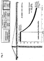
- FIG. 1 shows in a schematic representation of the upper portion of a tower crane with main boom 10 and counter-jib 20.
- the reference character g denotes the rope weight per meter of rope length (kg / m), f the rope sag, I the main boom length and the reference H the cable traction.
- the rope weight g and the boom length I are given.
- the maximum rope sag f is fixed, which is 5 to 6 m in the illustrated embodiment.
- the cable pull force and thus the hook weight can be determined. Since the cable traction and thus the hook weight is directly proportional to the rope weight, can be exercised by changing the weight of the rope a significant impact on the load hook weight and thus on the available payload, as exemplified in the Figures 2 and 3 evident.
- FIG. 1 further shows the storage drum 30, which is arranged in the spaced from the articulation point of the counter-jib 20 region of the counter jib 20, and by the reference numeral 40, the cable drive, which can be configured for example as a capstan drive or as a traction sheave drive.
- FIG. 2 shows the load curves for a tower crane when using a steel rope (St) and when using an aramid rope (F) as a hoist rope.
- the values given are for a 2-strand reeving with a maximum load of 12 t (steel rope).
- the comparison involved the use of a steel rope weighing 2.1 kg / m and an aramid rope weighing 0.945 kg / m.
- FIG. 3 The values for a hook height of 200 m and 4-strand design for a steel cable with a cable weight of 4.52 kg / m and for an aramid rope with a cable weight of 2.03 kg / m. How out FIG. 3 As can be seen, the maximum load is increased by approximately 8% and the peak load torque by approximately 290%.
Landscapes
- Engineering & Computer Science (AREA)
- Mechanical Engineering (AREA)
- Structural Engineering (AREA)
- Transportation (AREA)
- Jib Cranes (AREA)
- Ropes Or Cables (AREA)
- Load-Engaging Elements For Cranes (AREA)
- Control And Safety Of Cranes (AREA)
Abstract
Description
Die Erfindung betrifft einen Kran, mit einem oder mehreren Seilen beispielsweise zum Heben von Lasten oder zum Verstellen oder Abspannen eines Auslegers gemäß dem Oberbegriff des Anspruchs 1. Hebezeuge sind in zahlreichen unterschiedlichen Ausführungsformen bekannt. Insbesondere im Bereich der Krane besteht eine Vielfalt von Ausführungsvarianten, die unterschiedlichsten Anforderungen gerecht werden müssen.The invention relates to a crane, with one or more cables, for example for lifting loads or for adjusting or unclamping a boom according to the preamble of
Die bei bekannten Hebezeugen eingesetzten Seile bestehen aus einer Vielzahl von Stahldrähten, die zu Litzen verarbeitet sind. Üblicherweise bestehen die Seile aus einem Seilkern, der aus miteinander verseilten Litzen besteht. Um den Seilkern sind die Außenlitzen geschlagen. Die heute verwendeten Stahlseile sind in verschiedensten Ausführungen bekannt. Sie sind üblicherweise auf Seiltrommeln aufgewickelt, wobei aufgrund der Fähigkeit von Stahlseilen, Querkräfte aufzunehmen, eine Mehrlagenwicklung möglich und üblich ist.The ropes used in known hoists consist of a variety of steel wires, which are processed into strands. Usually, the ropes consist of a rope core, which consists of strands stranded together. The outer strands are beaten around the rope core. The steel cables used today are known in various designs. They are usually wound on cable drums, whereby due to the ability of steel cables to absorb shear forces, a multi-layer winding is possible and common.
Ein wesentlicher Nachteil der heute eingesetzten Stahlseile ist jedoch deren Gewicht, das je nach Seilausführung bei einem Seildurchmesser von 22 mm z.B. ca. 2,1 kg/m und bei einem Seildurchmeser von 30 mm z.B. ca. 4,5 kg/m beträgt. Das verhältnismäßig hohe Seilgewicht reduziert naturgemäß die Nutzlast des Hebezeuges bzw. steigert das Gesamtgewicht des Hebezeuges bzw. das Transportgewicht mobiler Hebezeuge, wie z.B. mobiler Krane.However, a major disadvantage of steel cables used today is their weight, which, depending on the cable design with a rope diameter of 22 mm, for. about 2.1 kg / m and at a rope diameter of 30 mm, e.g. about 4.5 kg / m. The relatively high rope weight naturally reduces the payload of the hoist or increases the total weight of the hoist or the transport weight of mobile hoists, such as e.g. mobile cranes.
Aus
Der vorliegenden Erfindung liegt daher die Aufgabe zugrunde, ein Hebezeug dahingehend weiterzubilden, daß dessen Gewicht verringert wird bzw. daß dessen Nutzlast gesteigert wird.The present invention is therefore the object of developing a hoist to the effect that its weight is reduced or that its payload is increased.
Diese Aufgabe wird durch ein Hebezeug mit den Merkmalen des Anspruchs 1 gelöst. Danach ist vorgesehen, dass es sich bei den Seilen zumindest teilweise um Faserseile handelt. Dies gilt für Hubseile zum Heben der Last oder Seile zum Verstellen eines Auslegers. Bei den Hebezeugen spielt das Seilgewicht eine wesentliche Rolle. Es führt zu einem Anstieg der Nutzlast bzw. zu einer Veringerung des Gesamtgewichtes bzw. des Transportgewichtes mobiler Krane.This object is achieved by a hoist with the features of
Bei dem Faserseil handelt es sich vorzugsweise um ein Aramidseil, d.h. um ein Seil das Aramidfasern aufweist oder aus diesen aufgebaut ist. Bei dem Werkstoff Aramid handelt es sich um aromatisches Polyamid mit hoher Festigkeit und geringem Gewicht. Das Gewicht eines Aramidseils bei vergleichbarer Bruchkraft beträgt nur ca. 45 % des Gewichtes eines Stahiseiles. Weitere Vorteile sind ein kleines D/d-Verhältnis, d.h. es lassen sich kleine Seilrollen-Durchmesser und damit kleinere Antriebe realisieren, sowie die hohe Lebensdauer bzgl. der BiegewechselFestigkeit, die um den Faktor 60 höher als die von Stahlseilen liegt. Ein weiterer Vorteil besteht in dem hohen Reibwert von 0,3 bis 0,6, der die Seile besonders geeignet für einen Treibscheibenantrieb macht. Ferner ist die geringe Geräuschentwicklung der Seile zu nennen.The fiber rope is preferably an aramid rope, i. around a rope has the aramid fibers or is composed of these. The material aramid is aromatic polyamide with high strength and low weight. The weight of an aramid rope at comparable breaking force is only about 45% of the weight of a Stahiseiles. Further advantages are a small D / d ratio, i. It can be small pulley diameter and thus smaller drives realize, as well as the long service life with respect. The flexural strength, which is higher by a factor of 60 than that of steel cables. Another advantage is the high coefficient of friction of 0.3 to 0.6, which makes the ropes particularly suitable for a traction sheave drive. Furthermore, the low noise of the ropes can be mentioned.
Bei heute bekannten Aramidseilen ist eine Mehrlagenwicklung insofern problematisch, als diese im Gegensatz zu Stahlseilen keine Querkräfte übertragen und einen großen Ovalisierungsgrad zeigen. Daraus ergibt sich, daß es von Vorteil ist, wenn nur Trommeln mit einlagiger Bewicklung eingesetzt werden allerdings verbunden mit dem Nachteil, daß nur geringe Hakenhöhen realisierbar sind. Grundsätzlich ist die Erfindung nicht auf Einlagenwicklungen beschränkt. Sofern Faserseile mit geringem Ovalisierungsgrad eingesetzt werden, ist auch bei diesen wie bei Stahlseilen eine übliche Mehrlagenwicklung im Bereich des Seilantriebes denkbar.In today known Aramidseilen a multi-layer winding is problematic insofar as they do not transmit transverse forces in contrast to steel cables and show a large degree of ovalization. It follows that it is advantageous if only drums are used with single-layer winding, however, associated with the disadvantage that only small hook heights can be realized. Basically, the invention is not limited to single-layer windings. If fiber ropes with a low degree of ovalization are used, a conventional multi-layer winding in the area of the rope drive is also conceivable for these, as in the case of steel ropes.
Gemäß der Erfindung ist ein Seilantrieb und eine Speichertrommel zur Aufwickelung des Seils vorgesehen. Die erforderliche Seilzugkraft wird durch den Seilantrieb aufgebracht. Der Seilantrieb kann z.B. als Spillantrieb oder als Treibscheibenantrieb ausgeführt sein. Die für das Heben der Last oder für das Bewegen eines Auslegers erforderliche Zugkraft wird durch die Treibscheibe oder durch den Spillkopf aufgebracht. Die Speichertrommel dient dazu, die nicht benötigte Seillänge aufzunehmen, wobei hier eine Mehrlagenwicklung denkbar ist, wenn die Zugkraft zum Aufwickeln des Seils auf die Speichertrommel entsprechend gering gewählt wird.According to the invention, a cable drive and a storage drum for winding the rope is provided. The required cable traction is applied by the cable drive. The cable drive may e.g. be designed as a capstan drive or as a traction sheave drive. The pulling force required to lift the load or to move a boom is applied by the traction sheave or by the spreader head. The storage drum serves to accommodate the unneeded rope length, in which case a multi-layer winding is conceivable if the tensile force for winding the rope on the storage drum is selected to be correspondingly low.
Bei dem Seilantrieb kann es sich z.B. um einen Hubantrieb oder auch um einen Ausleger-Verstellantrieb handeln. Auch andere Anwendungen sind möglich.The cable drive may be e.g. to act a lifting drive or even a boom adjustment. Other applications are possible.
Die Anordnung der Speichertrommel erfolgt gemäß Anspruch 1. Die Seilzuführung kann durch Umlenkungen den jeweiligen Treibscheiben oder dem Spillkopf zugeführt werden. Bei dem Hebezeug handelt es sich um einen Turmdrehkran, bei dem die Speichertrommel am Gegenausleger angeordnet ist. Die Speichertrommel kann auf großem Abstand zum Anlenkpunkt des Gegenauslegers plaziert werden. Der Seilantrieb, d.h. vorzugsweise der Spillantrieb bzw. der Treibscheibenantrieb kann beispielsweise an der Turmspitze angeordnet sein. Somit wäre ein ausreichender Abstand zwischen den beiden Positionen Antrieb und Trommel vorhanden, um auch eine Trommel mit der notwendigen Speichermöglichkeit ausführen.The arrangement of the storage drum is carried out according to
Gemäß der Erfindung ist die Speichertrommel so geschaltet, daß diese stets eine Zugkraft ausübt und damit das Seil bereits mit Vorspannung auf die jeweilige Antriebseinheit (z.B. Treibscheibenantrieb, Spillantrieb) einläuft. Bei einer derartigen Ausführung der Erfindung ergibt sich der Vorteil, daß die Vorspannung bzw. die Seilzugkraft derart eingestellt werden kann, daß die Speichertrommel mehrlagig bewickelt werden kann. Denkbar ist z.B. eine Seilzugkraft von einigen hundert Kilogramm. Die Bewicklung der Speichertrommel erfolgt vorzugsweise mittels einer Wickelvorrichtung.According to the invention, the storage drum is connected so that it always exerts a tensile force and thus the rope already with bias on the respective drive unit (for example traction sheave drive, spill drive) enters. In such an embodiment of the invention, there is the advantage that the bias or the cable tensile force can be adjusted so that the storage drum can be wound in multiple layers. It is conceivable, e.g. a cable traction of a few hundred kilograms. The winding of the storage drum is preferably carried out by means of a winding device.
In weiterer Ausgestaltung der Erfindung ist vorgesehen, daß die Seilführung derart erfolgt, daß das Seil eine 2-fache, 4-fache oder mehr als 4-fache Einscherung (x-fache Einscherung) aufweist. Speziell bei Autokranen sind 6-, 8-, 10-fache usw. Einscherungen keine Besonderheit. Die Seilführung hat einen erheblichen Einfluß auf das notwendige Hakengewicht und auf die Nutzlast, wie dies unten noch näher erläutert werden wird.In a further embodiment of the invention, it is provided that the cable guide is such that the rope has a 2-fold, 4-fold or more than 4-fold reeving (x-fold reeving). Especially with mobile cranes are 6-, 8-, 10-fold, etc. Shearing is not a special feature. The cable guide has a significant influence on the necessary hook weight and on the payload, as will be explained in more detail below.
Heute bekannte Aramidseile weisen die Eigenschaft eines Verdrehwinkeis im Bereich von 40° bis 120° bei voller Zugkraft auf. Um ein Eindrehen der Hakenflasche zu verhindern, kann in weiterer Ausgestaltung der Erfindung ein Drallkompensator vorgesehen sein, der dem Drehwinkelverhalten des Seils eine Gegendrehung entgegensetzt. Der Drallkompensator kann elektrisch betrieben sein und manuell oder automatisch eingesetzt werden. Er dient dazu, dem Drehwinkelverhalten des Seiles entgegenzuwirken. Sind Mittel zur Drehmomenterfassung vorhanden, könnte über diesen Drallkompensator automatisch gegengedreht werden. Vorzugsweise ist der Drallkompensator im Bereich des Seilendfestpunkts vorgesehen.Today known Aramidseile have the property of a turning angle in the range of 40 ° to 120 ° at full traction. In order to prevent screwing the hook bottle, a swirl compensator can be provided in a further embodiment of the invention, which opposes the rotation angle behavior of the rope counter rotation. The swirl compensator can be electrically operated and used manually or automatically. It serves to counteract the rotation angle behavior of the rope. If means for torque detection are available, it would be possible to counter-rotate automatically via this swirl compensator. Preferably, the swirl compensator is provided in the region of the rope endpoint.
Bei Turmdrehkranen ist von wesentlicher Bedeutung, daß das Seil immer von der Hubtrommel aus dem Bereich des Gegengewichtes quasi nach vorne bewegt wird. Dies bedeutet, bei großen Hakenhöhen werden mehrere Tonnen Seil vom Gegengewicht zur Position der Last transportiert. Bezogen auf das Lastmoment bedeutet dies eine Gegengewichtsabnahme und eine Eigengewichtszunahme. Ein geringeres Eigengewicht des Seils würde sich hinsichtlich der auftretenden Belastungen über die Stahlkonstruktion Turmspitze und Drehkranz positiv auswirken, da diese Plus-/Minusbelastung, sei es im Lastmoment oder Entlastung des Momentes wesentlich kleiner wird und dadurch auch Einfluß auf den Turm sowie auf den Drehkranz des Kranes bzw. Unterbau und Eckdrücke hat.In tower cranes is essential that the rope is always moved from the hoist drum from the range of counterweight almost forward. This means that with large hook heights, several tons of rope are transported by the counterweight to the position of the load. Relative to the load torque, this means a counterweight decrease and a self-weight increase. A smaller dead weight of the rope would have a positive effect on the loads occurring through the steel construction spire and slewing ring, as this plus / minus load, be it in the load torque or discharge of the moment becomes much smaller and thereby also influence the tower and the slewing ring of the Cranes or substructure and corner pressures has.
Weitere Einzelheiten und Vorteile der Erfindung werden anhand eines in der Zeichnung dargestellten Ausführungsbeispiels näher erläutert.
- Figur 1:
- Darstellung zur Ermittlung des Lasthakengewichtes in Abhängigkeit verschiedener Parameter bei einem Turmdrehkran,
Figur 2, 3:- Darstellung zur Verdeutlichung der Steigerung der Nutzlast anhand zweier unterschiedlicher Turmdrehkrane.
- FIG. 1:
- Representation for determining the load hook weight as a function of various parameters in a tower crane,
- 2, 3:
- Representation to illustrate the increase in payload using two different tower cranes.
Das Seilgewicht g und die Auslegerlänge I sind gegeben. Ebenso steht der maximale Seildurchhang f fest, der im darstellten Ausführungsbeispiel 5 bis 6 m beträgt. Mittels der in
Wie aus der Tabelle in
Diese erhebliche Steigerung der Spitzenlast fällt bei größeren Hakenhöhen und mehr als 2-facher Einscherung noch deutlicher aus.This significant increase in peak load falls at higher hook heights and more than 2-fold reeving even clearer.
Legt man die oben genannten Daten des Stahlseils sowie des Aramidseils zugrunde, ergibt sich bei einer Hakenhöhe von 200 m bereits eine Spitzenlastanhebung von 41 % und eine Anhebung der maximalen Traglast um ca. 7 %.Based on the above-mentioned data for the steel cable and the aramid rope, a hook height of 200 m already results in a peak load increase of 41% and an increase in the maximum load capacity of approx. 7%.
Bei Einsatz eines Stahlseils mit 20 t Maximallast (Seildurchmesser 30 mm, Seilgewicht 4,52 kg/m) ergibt sich im Vergleich zu einem Aramidseil mit einem Seilgewicht von 2,03 kg/m Folgendes: Bei einer Standard-Hakenhöhe von 60 m und 2-facher Einscherung ergibt sich bei Verwendung des Aramidseils eine Gewichtsersparnis (Lasthaken und Seil) von 850 kg, wodurch sich die Last an der Spitze von 5,4 t bei Einsatz eines Stahlseils auf 6,25 t, d.h. um ca. 16 % steigern läßt. Die Maximallast kann um ca. 4,3 % gesteigert werden. Bei einer Hakenhöhe von 200 m läßt sich eine Steigerung des Spitzenlastmomentes um ca. 37,4 % und der Maximallast um ca. 8,2 % erreichen.When using a steel cable with a maximum load of 20 t (
Der obige Effekt wirkt sich um so stärker aus, je größer der Kran ist. Bei Kranen, die mit 4-fach Einscherung arbeiten und auch über größere Höhen fahren, ergibt sich in dem oben genannten Beispiel (Hakenhöhe 60 m) mit einem Durchmesser des Stahlseils von 30 mm und einem Seilgewicht von 4,52 kg/m eine Spitzenlasterhöhung von ca. 47 % und eine Erhöhung der maximalen Traglast um ca. 4,25 %.The effect above affects the bigger the crane is. In cranes that work with 4-fold reeving and also go over greater heights, results in the above example (hook height 60 m) with a diameter of the steel cable of 30 mm and a cable weight of 4.52 kg / m, a peak load increase of about 47% and an increase in the maximum load capacity by about 4.25%.
Aus
Die genannten Beispiele zeigen, welchen erheblichen Einfluß das Seilgewicht auf das Lastmoment in Abhängigkeit von der Hubhöhe hat. Bei Kranen in der 20 t Ausführung sind entsprechend der obigen Beispiele bei freier Kranaufbauhöhe von ca. 60 m Spitzenlaststeigerungen von ca. 20 % und bei nicht seltenen Hubhöhen von 200 m bis nahezu 40 % möglich. Bei Großkranen mit großen Lasten, z.B. 40 t, die im 4-Strang-Betrieb arbeiten, ergeben sich Spitzenlaststeigerungen bei 60 m Aufbauhöhe von ca. 50 % und bei 200 m Hakenhöhe bis 290 %. Um mit heute üblichen Stahlseilen eine derartige Leistungssteigerung zu erzielen, müßten wesentlich größere, leistungsstärkere Hebezeuge, wie z.B. ein 400 mt-Kran anstelle eines 300 mt-Krans, mit höheren Kosten eingesetzt werden.The examples mentioned show the considerable influence that the cable weight has on the load torque as a function of the lifting height. For cranes in the 20 t version, peak load increases of approx. 20% and with not too high lift heights of 200 m to almost 40% are possible according to the above examples with a free crane installation height of approx. 60 m. For large cranes with large loads, e.g. 40 t, which work in 4-strand operation, result in peak load increases at 60 m installation height of approx. 50% and at 200 m hook height up to 290%. In order to achieve such an increase in performance with today's customary steel cables, substantially larger, more powerful hoists, such as e.g. a 400 m crane instead of a 300 m crane can be used at a higher cost.
Claims (9)
- A crane having one or more ropes, for example for the raising of loads or for the adjustment or guying of a jib, wherein at least some of the ropes are fibre ropes, characterised in that the crane has a rope drive and a storage drum for the winding up of the fibre rope, with the storage drum being connected such that a tensile force is always exerted onto the fibre rope so that the fibre rope runs onto the rope drive with pre-stress, with the crane being a tower crane and the storage drum being arranged at the counter-jib.
- A crane in accordance with claim 1, characterised in that the fibre ropes are aramid ropes.
- A crane in accordance with any one of the preceding claims, characterised in that the rope drive is made as a capstan drive or as a traction sheave drive.
- A crane in accordance with any one of the preceding claims, characterised in that the rope drive is a lift drive or a jib adjustment drive.
- A crane in accordance with any one of the preceding claims, characterised in that the rope drive is arranged in the region of the top of the tower.
- A crane in accordance with any one of the preceding claims, characterised in that a winding apparatus is provided by means of which the storage drum can be wound up in multiple layers.
- A crane in accordance with any one of the preceding claims, characterised in that the rope has two-fold, four-fold or more than four-fold reeving.
- A crane in accordance with any one of the preceding claims, characterised in that a twist compensator is provided which sets a counter-rotation against the angle of rotation behaviour of the rope.
- A crane in accordance with claim 8, characterised in that the twist compensator is operated electrically.
Applications Claiming Priority (2)
| Application Number | Priority Date | Filing Date | Title |
|---|---|---|---|
| DE102004055016 | 2004-11-15 | ||
| DE102005008087.1A DE102005008087B4 (en) | 2004-11-15 | 2005-02-22 | crane |
Publications (3)
| Publication Number | Publication Date |
|---|---|
| EP1657210A1 EP1657210A1 (en) | 2006-05-17 |
| EP1657210B1 EP1657210B1 (en) | 2010-01-27 |
| EP1657210B2 true EP1657210B2 (en) | 2018-01-17 |
Family
ID=35696006
Family Applications (1)
| Application Number | Title | Priority Date | Filing Date |
|---|---|---|---|
| EP05021048.3A Active EP1657210B2 (en) | 2004-11-15 | 2005-09-27 | Crane with fibre cable |
Country Status (4)
| Country | Link |
|---|---|
| EP (1) | EP1657210B2 (en) |
| AT (1) | ATE456538T1 (en) |
| DE (2) | DE102005008087B4 (en) |
| ES (1) | ES2339459T5 (en) |
Families Citing this family (6)
| Publication number | Priority date | Publication date | Assignee | Title |
|---|---|---|---|---|
| DE202009014031U1 (en) * | 2009-10-16 | 2009-12-24 | Manitowoc Crane Group France Sas | Synthetic rope as a carrier for cranes and other hoists |
| DE202011001846U1 (en) * | 2011-01-24 | 2012-04-30 | Liebherr-Components Biberach Gmbh | Device for detecting the Ablegereife a high-strength fiber rope when used on hoists |
| AT516444B1 (en) | 2014-11-05 | 2016-09-15 | Teufelberger Fiber Rope Gmbh | Rope made of textile fiber material |
| DE102015003981A1 (en) * | 2015-03-26 | 2016-09-29 | Liebherr-Werk Biberach Gmbh | Crane boom assembly |
| DE102015003982A1 (en) * | 2015-03-26 | 2016-09-29 | Liebherr-Werk Biberach Gmbh | crane tower |
| DE102020108990A1 (en) * | 2020-04-01 | 2021-10-07 | Liebherr-Werk Biberach Gmbh | Hoist like crane |
Citations (1)
| Publication number | Priority date | Publication date | Assignee | Title |
|---|---|---|---|---|
| GB2009077A (en) † | 1977-12-05 | 1979-06-13 | Pyramid Mfg Co | Winch Mechanism for Crane |
Family Cites Families (9)
| Publication number | Priority date | Publication date | Assignee | Title |
|---|---|---|---|---|
| DE2455273C3 (en) * | 1974-11-22 | 1978-01-19 | Feiten & Guilleaume Carlswerk AG, 5000 Köln | Plastic crane rope |
| DE2853661C2 (en) | 1978-12-13 | 1983-12-01 | Drahtseilwerk Saar GmbH, 6654 Kirkel | Synthetic fiber rope |
| DE3510116A1 (en) * | 1984-04-25 | 1985-10-31 | Liebherr-Werk Biberach Gmbh, 7950 Biberach | Tower crane slewing at the top |
| DE3937631A1 (en) | 1989-11-11 | 1991-05-16 | Saar Gmbh Drahtseilwerk | SWIVEL FOR FASTENING THE FIXED END OF AT LEAST ONE CRANE ROPE LOSELY ROLLING HOLDING THE LOAD RECEIVER |
| IL132299A (en) * | 1998-10-23 | 2003-10-31 | Inventio Ag | Stranded synthetic fiber rope |
| PE20001199A1 (en) * | 1998-10-23 | 2000-11-09 | Inventio Ag | SYNTHETIC FIBER CABLE |
| EP1004700B1 (en) * | 1998-11-25 | 2011-02-16 | Inventio AG | Synthetic fibre rope without a jacket and its corresponding method of manufacturing |
| EP1331191A1 (en) * | 2002-01-25 | 2003-07-30 | IHC Gusto Engineering B.V. | Floating lifting device |
| DE20202989U1 (en) * | 2002-02-25 | 2002-06-13 | Müller, Wolfgang T., 78315 Radolfzell | Hybrid rope for lifting and transport equipment, especially for lifts |
-
2005
- 2005-02-22 DE DE102005008087.1A patent/DE102005008087B4/en active Active
- 2005-09-27 ES ES05021048.3T patent/ES2339459T5/en active Active
- 2005-09-27 EP EP05021048.3A patent/EP1657210B2/en active Active
- 2005-09-27 AT AT05021048T patent/ATE456538T1/en not_active IP Right Cessation
- 2005-09-27 DE DE502005008939T patent/DE502005008939D1/en active Active
Patent Citations (1)
| Publication number | Priority date | Publication date | Assignee | Title |
|---|---|---|---|---|
| GB2009077A (en) † | 1977-12-05 | 1979-06-13 | Pyramid Mfg Co | Winch Mechanism for Crane |
Also Published As
| Publication number | Publication date |
|---|---|
| DE502005008939D1 (en) | 2010-03-18 |
| DE102005008087B4 (en) | 2023-10-05 |
| ATE456538T1 (en) | 2010-02-15 |
| ES2339459T3 (en) | 2010-05-20 |
| EP1657210A1 (en) | 2006-05-17 |
| DE102005008087A1 (en) | 2006-05-24 |
| ES2339459T5 (en) | 2018-04-30 |
| EP1657210B1 (en) | 2010-01-27 |
Similar Documents
| Publication | Publication Date | Title |
|---|---|---|
| EP3365492B1 (en) | High-strength fiber rope for lifting devices such as cranes | |
| EP1657210B2 (en) | Crane with fibre cable | |
| EP2435352B1 (en) | Traveling crane having traveler and hoisting winch | |
| EP3359482B1 (en) | Rope drum and fiber rope drive having such a rope drum | |
| EP1924520B1 (en) | Combination double bottom hook block | |
| EP3038967B1 (en) | Device for detecting the replacement state of wear of a high-strength fibre rope during use in lifting gear | |
| DE102017117121B4 (en) | crane | |
| EP1780164B2 (en) | Pulley block with a hook for a crane | |
| CN101618840B (en) | Telescopic crane and superlift device thereof | |
| EP1266861B1 (en) | Telescopic crane with a superlift device | |
| EP3038968A1 (en) | Device for detecting the replacement state of wear of a high-strength fibre rope during use in lifting gear | |
| EP3038966B1 (en) | Swivel | |
| CN202296903U (en) | Winch locking device, tightening device and crane | |
| EP2984020B1 (en) | Crane, as well as method for testing the cabling of such crane | |
| DE202011001850U1 (en) | crane | |
| DE19731049B4 (en) | Crane with bridge jib | |
| DE102004054096B4 (en) | Derrick | |
| EP1460025B1 (en) | Hoist with two load carrier cables | |
| DE8334660U1 (en) | LIFTING DEVICE | |
| EP1947051A3 (en) | Elevation cable tackle system | |
| DE19933771B4 (en) | crane | |
| DE102004046130A1 (en) | Winch system for mobile crane includes a friction winch for a controlled lowering of heavy loads | |
| DE102016011217A1 (en) | Articulated boom crane with rope drive | |
| DE102019212541B3 (en) | Cable winch arrangement for a crane and crane | |
| DE102022111813A1 (en) | hoist |
Legal Events
| Date | Code | Title | Description |
|---|---|---|---|
| PUAI | Public reference made under article 153(3) epc to a published international application that has entered the european phase |
Free format text: ORIGINAL CODE: 0009012 |
|
| AK | Designated contracting states |
Kind code of ref document: A1 Designated state(s): AT BE BG CH CY CZ DE DK EE ES FI FR GB GR HU IE IS IT LI LT LU LV MC NL PL PT RO SE SI SK TR |
|
| AX | Request for extension of the european patent |
Extension state: AL BA HR MK YU |
|
| 17P | Request for examination filed |
Effective date: 20060718 |
|
| 17Q | First examination report despatched |
Effective date: 20060914 |
|
| AKX | Designation fees paid |
Designated state(s): AT BE BG CH CY CZ DE DK EE ES FI FR GB GR HU IE IS IT LI LT LU LV MC NL PL PT RO SE SI SK TR |
|
| RTI1 | Title (correction) |
Free format text: CRANE WITH FIBRE CABLE |
|
| GRAP | Despatch of communication of intention to grant a patent |
Free format text: ORIGINAL CODE: EPIDOSNIGR1 |
|
| GRAS | Grant fee paid |
Free format text: ORIGINAL CODE: EPIDOSNIGR3 |
|
| GRAA | (expected) grant |
Free format text: ORIGINAL CODE: 0009210 |
|
| AK | Designated contracting states |
Kind code of ref document: B1 Designated state(s): AT BE BG CH CY CZ DE DK EE ES FI FR GB GR HU IE IS IT LI LT LU LV MC NL PL PT RO SE SI SK TR |
|
| REG | Reference to a national code |
Ref country code: GB Ref legal event code: FG4D Free format text: NOT ENGLISH |
|
| REG | Reference to a national code |
Ref country code: CH Ref legal event code: EP Ref country code: CH Ref legal event code: NV Representative=s name: BOVARD AG PATENTANWAELTE |
|
| REG | Reference to a national code |
Ref country code: IE Ref legal event code: FG4D |
|
| REF | Corresponds to: |
Ref document number: 502005008939 Country of ref document: DE Date of ref document: 20100318 Kind code of ref document: P |
|
| REG | Reference to a national code |
Ref country code: ES Ref legal event code: FG2A Ref document number: 2339459 Country of ref document: ES Kind code of ref document: T3 |
|
| REG | Reference to a national code |
Ref country code: NL Ref legal event code: VDEP Effective date: 20100127 |
|
| LTIE | Lt: invalidation of european patent or patent extension |
Effective date: 20100127 |
|
| PG25 | Lapsed in a contracting state [announced via postgrant information from national office to epo] |
Ref country code: IS Free format text: LAPSE BECAUSE OF FAILURE TO SUBMIT A TRANSLATION OF THE DESCRIPTION OR TO PAY THE FEE WITHIN THE PRESCRIBED TIME-LIMIT Effective date: 20100527 Ref country code: LT Free format text: LAPSE BECAUSE OF FAILURE TO SUBMIT A TRANSLATION OF THE DESCRIPTION OR TO PAY THE FEE WITHIN THE PRESCRIBED TIME-LIMIT Effective date: 20100127 Ref country code: PT Free format text: LAPSE BECAUSE OF FAILURE TO SUBMIT A TRANSLATION OF THE DESCRIPTION OR TO PAY THE FEE WITHIN THE PRESCRIBED TIME-LIMIT Effective date: 20100527 Ref country code: NL Free format text: LAPSE BECAUSE OF FAILURE TO SUBMIT A TRANSLATION OF THE DESCRIPTION OR TO PAY THE FEE WITHIN THE PRESCRIBED TIME-LIMIT Effective date: 20100127 |
|
| REG | Reference to a national code |
Ref country code: IE Ref legal event code: FD4D |
|
| PG25 | Lapsed in a contracting state [announced via postgrant information from national office to epo] |
Ref country code: PL Free format text: LAPSE BECAUSE OF FAILURE TO SUBMIT A TRANSLATION OF THE DESCRIPTION OR TO PAY THE FEE WITHIN THE PRESCRIBED TIME-LIMIT Effective date: 20100127 Ref country code: SI Free format text: LAPSE BECAUSE OF FAILURE TO SUBMIT A TRANSLATION OF THE DESCRIPTION OR TO PAY THE FEE WITHIN THE PRESCRIBED TIME-LIMIT Effective date: 20100127 Ref country code: LV Free format text: LAPSE BECAUSE OF FAILURE TO SUBMIT A TRANSLATION OF THE DESCRIPTION OR TO PAY THE FEE WITHIN THE PRESCRIBED TIME-LIMIT Effective date: 20100127 Ref country code: FI Free format text: LAPSE BECAUSE OF FAILURE TO SUBMIT A TRANSLATION OF THE DESCRIPTION OR TO PAY THE FEE WITHIN THE PRESCRIBED TIME-LIMIT Effective date: 20100127 |
|
| PLBI | Opposition filed |
Free format text: ORIGINAL CODE: 0009260 |
|
| PG25 | Lapsed in a contracting state [announced via postgrant information from national office to epo] |
Ref country code: RO Free format text: LAPSE BECAUSE OF FAILURE TO SUBMIT A TRANSLATION OF THE DESCRIPTION OR TO PAY THE FEE WITHIN THE PRESCRIBED TIME-LIMIT Effective date: 20100127 Ref country code: IE Free format text: LAPSE BECAUSE OF FAILURE TO SUBMIT A TRANSLATION OF THE DESCRIPTION OR TO PAY THE FEE WITHIN THE PRESCRIBED TIME-LIMIT Effective date: 20100127 Ref country code: GR Free format text: LAPSE BECAUSE OF FAILURE TO SUBMIT A TRANSLATION OF THE DESCRIPTION OR TO PAY THE FEE WITHIN THE PRESCRIBED TIME-LIMIT Effective date: 20100428 Ref country code: CY Free format text: LAPSE BECAUSE OF FAILURE TO SUBMIT A TRANSLATION OF THE DESCRIPTION OR TO PAY THE FEE WITHIN THE PRESCRIBED TIME-LIMIT Effective date: 20100127 Ref country code: EE Free format text: LAPSE BECAUSE OF FAILURE TO SUBMIT A TRANSLATION OF THE DESCRIPTION OR TO PAY THE FEE WITHIN THE PRESCRIBED TIME-LIMIT Effective date: 20100127 Ref country code: SE Free format text: LAPSE BECAUSE OF FAILURE TO SUBMIT A TRANSLATION OF THE DESCRIPTION OR TO PAY THE FEE WITHIN THE PRESCRIBED TIME-LIMIT Effective date: 20100127 |
|
| 26 | Opposition filed |
Opponent name: MANITOWOC CRANE GROUP GERMANY GMBH Effective date: 20101012 |
|
| PG25 | Lapsed in a contracting state [announced via postgrant information from national office to epo] |
Ref country code: BG Free format text: LAPSE BECAUSE OF FAILURE TO SUBMIT A TRANSLATION OF THE DESCRIPTION OR TO PAY THE FEE WITHIN THE PRESCRIBED TIME-LIMIT Effective date: 20100427 Ref country code: SK Free format text: LAPSE BECAUSE OF FAILURE TO SUBMIT A TRANSLATION OF THE DESCRIPTION OR TO PAY THE FEE WITHIN THE PRESCRIBED TIME-LIMIT Effective date: 20100127 Ref country code: CZ Free format text: LAPSE BECAUSE OF FAILURE TO SUBMIT A TRANSLATION OF THE DESCRIPTION OR TO PAY THE FEE WITHIN THE PRESCRIBED TIME-LIMIT Effective date: 20100127 |
|
| PG25 | Lapsed in a contracting state [announced via postgrant information from national office to epo] |
Ref country code: DK Free format text: LAPSE BECAUSE OF FAILURE TO SUBMIT A TRANSLATION OF THE DESCRIPTION OR TO PAY THE FEE WITHIN THE PRESCRIBED TIME-LIMIT Effective date: 20100127 |
|
| PLAX | Notice of opposition and request to file observation + time limit sent |
Free format text: ORIGINAL CODE: EPIDOSNOBS2 |
|
| BERE | Be: lapsed |
Owner name: LIEBHERR-WERK BIBERACH G.M.B.H. Effective date: 20100930 |
|
| REG | Reference to a national code |
Ref country code: CH Ref legal event code: PFA Owner name: LIEBHERR-WERK BIBERACH GMBH Free format text: LIEBHERR-WERK BIBERACH GMBH#HANS-LIEBHERR-STRASSE 45#88400 BIBERACH (DE) -TRANSFER TO- LIEBHERR-WERK BIBERACH GMBH#HANS-LIEBHERR-STRASSE 45#88400 BIBERACH (DE) |
|
| PG25 | Lapsed in a contracting state [announced via postgrant information from national office to epo] |
Ref country code: MC Free format text: LAPSE BECAUSE OF NON-PAYMENT OF DUE FEES Effective date: 20100930 |
|
| GBPC | Gb: european patent ceased through non-payment of renewal fee |
Effective date: 20100927 |
|
| PG25 | Lapsed in a contracting state [announced via postgrant information from national office to epo] |
Ref country code: BE Free format text: LAPSE BECAUSE OF NON-PAYMENT OF DUE FEES Effective date: 20100930 |
|
| PLAF | Information modified related to communication of a notice of opposition and request to file observations + time limit |
Free format text: ORIGINAL CODE: EPIDOSCOBS2 |
|
| PG25 | Lapsed in a contracting state [announced via postgrant information from national office to epo] |
Ref country code: GB Free format text: LAPSE BECAUSE OF NON-PAYMENT OF DUE FEES Effective date: 20100927 |
|
| PLBB | Reply of patent proprietor to notice(s) of opposition received |
Free format text: ORIGINAL CODE: EPIDOSNOBS3 |
|
| PG25 | Lapsed in a contracting state [announced via postgrant information from national office to epo] |
Ref country code: AT Free format text: LAPSE BECAUSE OF NON-PAYMENT OF DUE FEES Effective date: 20100927 |
|
| APAH | Appeal reference modified |
Free format text: ORIGINAL CODE: EPIDOSCREFNO |
|
| APBM | Appeal reference recorded |
Free format text: ORIGINAL CODE: EPIDOSNREFNO |
|
| APBP | Date of receipt of notice of appeal recorded |
Free format text: ORIGINAL CODE: EPIDOSNNOA2O |
|
| PG25 | Lapsed in a contracting state [announced via postgrant information from national office to epo] |
Ref country code: LU Free format text: LAPSE BECAUSE OF NON-PAYMENT OF DUE FEES Effective date: 20100927 Ref country code: HU Free format text: LAPSE BECAUSE OF FAILURE TO SUBMIT A TRANSLATION OF THE DESCRIPTION OR TO PAY THE FEE WITHIN THE PRESCRIBED TIME-LIMIT Effective date: 20100728 |
|
| PG25 | Lapsed in a contracting state [announced via postgrant information from national office to epo] |
Ref country code: TR Free format text: LAPSE BECAUSE OF FAILURE TO SUBMIT A TRANSLATION OF THE DESCRIPTION OR TO PAY THE FEE WITHIN THE PRESCRIBED TIME-LIMIT Effective date: 20100127 |
|
| APBQ | Date of receipt of statement of grounds of appeal recorded |
Free format text: ORIGINAL CODE: EPIDOSNNOA3O |
|
| REG | Reference to a national code |
Ref country code: FR Ref legal event code: PLFP Year of fee payment: 12 |
|
| APBU | Appeal procedure closed |
Free format text: ORIGINAL CODE: EPIDOSNNOA9O |
|
| REG | Reference to a national code |
Ref country code: FR Ref legal event code: PLFP Year of fee payment: 13 |
|
| PUAH | Patent maintained in amended form |
Free format text: ORIGINAL CODE: 0009272 |
|
| STAA | Information on the status of an ep patent application or granted ep patent |
Free format text: STATUS: PATENT MAINTAINED AS AMENDED |
|
| 27A | Patent maintained in amended form |
Effective date: 20180117 |
|
| AK | Designated contracting states |
Kind code of ref document: B2 Designated state(s): AT BE BG CH CY CZ DE DK EE ES FI FR GB GR HU IE IS IT LI LT LU LV MC NL PL PT RO SE SI SK TR |
|
| REG | Reference to a national code |
Ref country code: DE Ref legal event code: R102 Ref document number: 502005008939 Country of ref document: DE |
|
| REG | Reference to a national code |
Ref country code: CH Ref legal event code: AELC |
|
| REG | Reference to a national code |
Ref country code: ES Ref legal event code: DC2A Ref document number: 2339459 Country of ref document: ES Kind code of ref document: T5 Effective date: 20180430 |
|
| REG | Reference to a national code |
Ref country code: FR Ref legal event code: PLFP Year of fee payment: 14 |
|
| P01 | Opt-out of the competence of the unified patent court (upc) registered |
Effective date: 20230630 |
|
| PGFP | Annual fee paid to national office [announced via postgrant information from national office to epo] |
Ref country code: FR Payment date: 20230922 Year of fee payment: 19 Ref country code: DE Payment date: 20230928 Year of fee payment: 19 |
|
| PGFP | Annual fee paid to national office [announced via postgrant information from national office to epo] |
Ref country code: ES Payment date: 20231002 Year of fee payment: 19 |
|
| PGFP | Annual fee paid to national office [announced via postgrant information from national office to epo] |
Ref country code: IT Payment date: 20230927 Year of fee payment: 19 Ref country code: CH Payment date: 20231002 Year of fee payment: 19 |