EP1657131A1 - Ralentisseur pour luge - Google Patents
Ralentisseur pour luge Download PDFInfo
- Publication number
- EP1657131A1 EP1657131A1 EP05110567A EP05110567A EP1657131A1 EP 1657131 A1 EP1657131 A1 EP 1657131A1 EP 05110567 A EP05110567 A EP 05110567A EP 05110567 A EP05110567 A EP 05110567A EP 1657131 A1 EP1657131 A1 EP 1657131A1
- Authority
- EP
- European Patent Office
- Prior art keywords
- housing
- fluid
- axle
- section
- driven vehicle
- Prior art date
- Legal status (The legal status is an assumption and is not a legal conclusion. Google has not performed a legal analysis and makes no representation as to the accuracy of the status listed.)
- Granted
Links
Images


Classifications
-
- B—PERFORMING OPERATIONS; TRANSPORTING
- B62—LAND VEHICLES FOR TRAVELLING OTHERWISE THAN ON RAILS
- B62B—HAND-PROPELLED VEHICLES, e.g. HAND CARTS OR PERAMBULATORS; SLEDGES
- B62B3/00—Hand carts having more than one axis carrying transport wheels; Steering devices therefor; Equipment therefor
- B62B3/007—Coaster wagons
-
- B—PERFORMING OPERATIONS; TRANSPORTING
- B60—VEHICLES IN GENERAL
- B60T—VEHICLE BRAKE CONTROL SYSTEMS OR PARTS THEREOF; BRAKE CONTROL SYSTEMS OR PARTS THEREOF, IN GENERAL; ARRANGEMENT OF BRAKING ELEMENTS ON VEHICLES IN GENERAL; PORTABLE DEVICES FOR PREVENTING UNWANTED MOVEMENT OF VEHICLES; VEHICLE MODIFICATIONS TO FACILITATE COOLING OF BRAKES
- B60T1/00—Arrangements of braking elements, i.e. of those parts where braking effect occurs specially for vehicles
- B60T1/02—Arrangements of braking elements, i.e. of those parts where braking effect occurs specially for vehicles acting by retarding wheels
-
- B—PERFORMING OPERATIONS; TRANSPORTING
- B60—VEHICLES IN GENERAL
- B60T—VEHICLE BRAKE CONTROL SYSTEMS OR PARTS THEREOF; BRAKE CONTROL SYSTEMS OR PARTS THEREOF, IN GENERAL; ARRANGEMENT OF BRAKING ELEMENTS ON VEHICLES IN GENERAL; PORTABLE DEVICES FOR PREVENTING UNWANTED MOVEMENT OF VEHICLES; VEHICLE MODIFICATIONS TO FACILITATE COOLING OF BRAKES
- B60T10/00—Control or regulation for continuous braking making use of fluid or powdered medium, e.g. for use when descending a long slope
- B60T10/02—Control or regulation for continuous braking making use of fluid or powdered medium, e.g. for use when descending a long slope with hydrodynamic brake
-
- B—PERFORMING OPERATIONS; TRANSPORTING
- B62—LAND VEHICLES FOR TRAVELLING OTHERWISE THAN ON RAILS
- B62B—HAND-PROPELLED VEHICLES, e.g. HAND CARTS OR PERAMBULATORS; SLEDGES
- B62B15/00—Other sledges; Ice boats or sailing sledges
- B62B15/008—Wheeled sledges
-
- B—PERFORMING OPERATIONS; TRANSPORTING
- B62—LAND VEHICLES FOR TRAVELLING OTHERWISE THAN ON RAILS
- B62B—HAND-PROPELLED VEHICLES, e.g. HAND CARTS OR PERAMBULATORS; SLEDGES
- B62B5/00—Accessories or details specially adapted for hand carts
- B62B5/04—Braking mechanisms; Locking devices against movement
-
- B—PERFORMING OPERATIONS; TRANSPORTING
- B62—LAND VEHICLES FOR TRAVELLING OTHERWISE THAN ON RAILS
- B62B—HAND-PROPELLED VEHICLES, e.g. HAND CARTS OR PERAMBULATORS; SLEDGES
- B62B5/00—Accessories or details specially adapted for hand carts
- B62B5/0026—Propulsion aids
- B62B5/0069—Control
Definitions
- This invention relates generally to a speed control mechanism and, more particularly, to a speed restrictor for a gravity driven vehicle, such as, for example, an alpine sled, bobsled, soap box car, racing cart and the like.
- ski resorts provide a ride down a mountain on a track using a sled.
- the track typically consists of an assembly of prefabricated sections having a variety of different curves and straight sections.
- the track is designed and installed to conform to the terrain of the mountain and may vary from 1000 to 5000 feet in length depending on the vertical drop between the start and finish.
- the tracks are usually installed on a roadbed, in ground, with a pitch varying from, for example, 10 to 22 percent.
- the track may also be a road, path or other terrain having a pitch or slope.
- Conventional sleds use runners for gliding, wheels for providing acceleration and rubber strips for braking.
- Each sled is designed to carry one rider that controls the speed of the sled using a control stick.
- the control stick provides acceleration - by moving the stick forward, gliding - by moving the stick to a middle position, and braking - by moving the stick to a rear position.
- a track having a high pitch typically uses a sled with front wheels attached to the control stick and runners. As the control stick is moved forward, the wheels lift a portion of the sled chassis away from the track, causing less friction by the runners on the track.
- a track having a lower pitch typically uses a sled having front and rear wheels and runners. The rear wheels are necessary on lower pitch tracks because of the friction generated by the runners on the track, e.g. the sled would not make it down the track otherwise. Rear wheels are not provided for conventional sleds used on higher pitched tracks because the sled would gain too much speed.
- a sled without rear wheels will "fishtail", while a sled with rear wheels will not. Therefore, a sled with rear wheels is more stable and less susceptible to accidents, but not usable on a higher pitch tracks because it causes the sled to travel too fast.
- a speed control mechanism constructed in accordance with one or more aspects of the present invention restricts the speed of a gravity driven vehicle to enable the use of sleds having rear wheels to travel down high pitched tracks or terrain.
- the present invention provides, in one aspect, a speed restrictor for a gravity driven vehicle.
- the speed restrictor includes a housing containing a fluid and mountable to a chassis of the gravity driven vehicle.
- the speed restrictor also includes at least one rotor mounted on at least one wheel axle of the gravity driven vehicle within the housing.
- the at least one rotor has an outer periphery surface facing an inner surface of the housing, wherein rotation of the at least one wheel axle slows in response to resistance caused by fluid being forced against the inner surface of the housing during rotation of the at least one wheel axle.
- a hydraulic speed restrictor attached to a rear axle assembly of a gravity driven vehicle to allow for more stable, safer and enjoyable rides.
- the speed restrictor will be described in reference to an alpine sled, but it should be understood that the speed restrictor can also be used on other gravity driven vehicles that require control of speed down high pitched terrain, such as, for example, soap box cars, bobsleds, racing carts and the like. Also, it is understood that the speed restrictor can also be applied to a front axle assembly or one or more axle assemblies of a gravity driven vehicle.
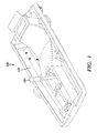
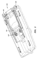
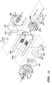
- Fig 1 and 2 illustrate the top and undercarriage, respectively, of one example of an alpine sled 100 that can be adapted to incorporate a speed restrictor constructed in accordance with one or more aspects of the present invention.
- Alpine sled 100 includes a chassis 110 for supporting a rider on a top side and a control stick 120 for controlling the acceleration and braking of the sled.
- Control stick 120 extends through chassis 110 and connects to a front axle assembly of a typical drivetrain mechanism for an alpine sled, which is connected to the undercarriage (fig 2) of chassis 110.
- Drivetrain mechanism includes an assembly of runners 130 and the front axle assembly connected to front wheels 140 used to accelerate and brake sled 100.
- Control stick 120 is utilized to control the use and contact of front wheels 140 and runners 130 with respect to the surface of the track. For example, as control stick 120 is pushed forward, runners 130 are lifted off the ground, causing alpine sled 100 to move with less friction by using front wheels 140.
- Sled 100 also includes a rear axle assembly 150 including rear wheels 152.
- Rear axle assembly 150 is mounted to the undercarriage of chassis 110.
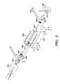
- Fig 3 illustrates one embodiment of rear axle assembly 150 including a speed restrictor 300 constructed according to the principles of the present invention.
- rear axle assembly 150 includes rear wheels 152 mounted on wheel hubs 154 engaging ends of rear axles 156, 158. The other ends of rear axles 156, 158 engage speed restrictor 300.
- a mounting assembly mounts rear axle assembly 150 to the undercarriage of chassis 110.
- Mounting assembly includes brackets 180 connected to the undercarriage of chassis 110, and through which rear axles 156, 158 pass, and a mounting plate 182 connected to housing 300 of speed restrictor.
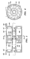
- FIG. 4 A first embodiment of speed restrictor constructed in accordance with one or more aspects of the present invention is illustrated in fig 4 through 6.
- Fig 4 and 5 illustrate a speed restrictor utilizing two rear axles 156, 158, split in the middle between rear wheels 152, and two rotors 410, 420 engaging ends of rear axles 156, 158.
- Speed restrictor includes a housing 300 (which is cut away in fig 4 to show the interior wall of housing 300) having a first side 404 and a second side 406 bolted, secured or affixed to housing 300 with an o-ring 407 to provide sealing.
- Bearings 452 for rotation of rear axles 156, 158 are provided at the locations where rear axles 156, 158 pass through first and second sides 404, 406 of housing 300.
- Housing 300 including first side 404 and second side 406, form a cavity for holding a fluid.
- First side 404 and second side 406 each have a flange 405 for attaching to mounting plate 182 (fig 3).
- the central portion of the interior wall of housing 300 between first side 404 and second side 406 includes a rough surface 402 including, for example, a plurality of ridges and valleys.
- a seal 500 is also provided at the location rear axles 156 and 158 pass through first side 404 and second side 406.
- a connector 452 is telescopically received and secured near the ends of rear axles 156, 158.
- Connectors 452 engage rotors 410 and 420 and cause rotors 410, 420 to rotate with rear axles 156, 158, respectively, and rear wheels 152.
- Rotor 410 includes a first side 412 facing a first side 422 of rotor 420 and a second side 414 facing first side 404 of housing 300.
- Rotor 420 includes a second side 424 facing second side 406 of housing 300.
- Rotor 410 also includes a center hub 416 that receives a center hub 426 of rotor 412. Center hubs 416 and 426 assist with the proper alignment of rear axles 156 and 158 but do not effect the rotation of the other axles.
- a plurality of holes 430 surround center hubs 416 and 426 of rotors 410, 420.
- a plate 418 including a plurality of holes 419 is positioned adjacent second side 414 of rotor 410 and a plate 428 also including a plurality of holes 429 is positioned adjacent second side 424 of rotor 420.
- the plurality of holes 419, 429 formed in plates 418, 429, respectively, and the plurality of holes 430 formed in hubs 416, 426 of rotors 410, 420, respectively, provide fluid communication between the middle section of housing 300 and two outer fluid compartments 502, 504 to permit circulation of fluid during operation. Without these bypass holes, the operation of the rotors would run without circulation and continue to churn the same portion of fluid without any discharge to fluid compartments 502, 504.
- second sides 414 and 424 of rotors 410, 420 include a plurality of rotor blades 702 having narrow fluid channels (e.g. 704) and wide tips.
- Various other embodiments showing a plurality of rotor blades on second sides 414 and 424 of rotors 410, 420, respectively, that may be used in the speed restrictor constructed in accordance with the principles of the present invention, are illustrated in fig 6 through 10B in which inch units are used.
- the number and angles of fluid channels and rotor blades and the profiles of the same can affect the specific performance of the sled (e.g. drag v. speed) depending on the conditions of the track and desired speed.
- rotor blades may be similar to a centrifugal pump impeller.
- Each of these rotor designs may vary in the width of the blade tips, angle of the blades, spacing of the blades, dimensions, number of blades used and other relevant characteristics known in the art.
- the performance of speed restrictor can be affected by the type of fluid used. For example, the thicker the fluid used, the more resistance provided to the operation of the rotors used in the speed restrictor. The amount of resistance depends on the fluid viscosity. Variations from very little resistance to very high resistance depend on the fluid used. The type of fluid viscosity used also depends on the pitch of the slide or track. Although petroleum fluid may be used, it has been determined that petroleum fluid does not retain its initial viscosity as the friction energy is absorbed. During testing, the drag resistance of the restrictor declined by as much as 40% with a temperature rise of less than 100 degrees Fahrenheit. This loss of resistance diminishes the desired function of the speed restrictor.
- Silicone fluid provides a more desired performance than petroleum fluid because it loses less viscosity with similar temperature rise.
- a reduction of less than 2% resistance was registered in four minutes of running time with an RPM representing a speed of 22 miles per hour and a temperature rise of about 70 degrees Fahrenheit. Therefore, silicone fluid or a fluid with similar temperature stability characteristics offer better performance results with a speed restrictor constructed in accordance with the principles of the present invention.
- the speed of the sled is limited by using a speed restrictor constructed in accordance with the principles of the present invention.
- rear wheels 152 rotate, causing rear axles 156, 158 to simultaneously rotate.
- the rotation of rear axles 156, 158 cause their respective rotors 410, 420 to also simultaneously rotate.
- the rotation of rotors 410, 420 causes fluid contained in housing 300 to circulate and forces fluid against the rough interior surface 402 of housing 300.
- rear axle assembly may utilize one axle 1202 having a speed restrictor using one rotor 1204. In other embodiments, rear axle assembly may utilize more than two rear axles (e.g. three axles) and speed restrictors using one or more rotors.
- single axle 1202 passes through housing 300 and out first and second sides 404, 406. Seals 500 and o-rings or washers 407, to prevent leakage of the fluid contained within housing 300, and bearings 452, to provide for the rotation of single axle 1202, are provided at the locations where single axle 1202 passes through first and second sides 404, 406 of housing 300.
- Single rotor 1202 includes rotor blades on the opposing sides facing plates 418, 429 that are designed as previously discussed for rotors 410, 420.
- Fig 12 illustrates another embodiment of a speed restrictor constructed in accordance with the principles of the present invention for an alpine sled.
- rear axle assembly includes a center axle 1302 connecting to wheel axles 1304, 1306 for rear wheels 152.
- Speed restrictor 1302 includes a hydraulic unit comprising a gear housing 1328 and a sealed fluid container 1314 to circulate a fluid to regulate the rotation of center axle 1302.
- Gear housing 1328 contains a first hydraulic pump gear 1320 and a second hydraulic pump gear 1322.
- First hydraulic pump gear 320 passes through and rotates with center axle 1302.
- first hydraulic pump gear 1320 meshes with and drives second hydraulic pump gear 1322.
- a pump gear shaft 1324 supports the second hydraulic pump gear 1322.
- Floating pump bearings 1326 are positioned on both sides of first and second hydraulic pump gears 1320, 1322 to permit rotation of center axle 1302 and pump shaft 1324.
- Gear pump housing 1328 and an external side 1316 of fluid container 1314 form a cavity that houses first and second hydraulic gears 1320, 1324 and floating pump bearings 1326 and is in fluid communication with fluid container 314.
- first and second hydraulic pump gears 1320, 1324 As first and second hydraulic pump gears 1320, 1324 come out of mesh, they create expanding volume on the inlet side of the gear pump. Fluid flows from fluid container 1314 through an intake 1318 formed in side 1316 of fluid container 1314 into gear pump housing 1328. The meshing of pump gears 1320, 1322 forces (e.g. under pressure) the fluid through an outlet port 1319 back into the fluid container. Flow restrictor or orifice 1312 is located in outlet port 1319 to regulate the amount of pumped fluid through outlet port 1319 to fluid container 1314 during rotation of first and second hydraulic gears 1320, 1322.
- center axle 1302 passes through gear pump housing 1328 and sealed fluid container 1314, respectively, and connect to axles 1304, 1306 for rear wheels 152.
- a seal 1340 such as for example, a double lip oil seal, is positioned at both ends of center axle 1302 exiting gear pump housing 1328 and fluid container 1314 to prevent leaking of the fluid.
- Each of rear wheels 152 connect to a wheel hub 1350 mounted on one end of a wheel shaft 304.
- the other end of wheel axle 1304 includes a one-way roller clutch 1352 engaging the end of main axle shaft 1302. Due to the clutches, the faster wheel axle controls the gear pump.
- the clutches 1352 are necessary as the wheels 152 turn at different speeds in the curves of the track.
- a bearing 1360 such as, for example, a double sealed bearing, is mounted between the two ends of the wheel shaft for mounting on chassis 200 of sled 100.
- Wheel axles 1304, 1306, either individually or with the other wheel axle, powers the gear pump as the sled moves down the track.
- rear wheels 152 cause wheel axles 1304, 1306 to rotate, which, in turn, causes center axle 1302 to rotate.
- the rotation of center axle 1302 causes first hydraulic pump gear 1320 to turn. Due to the meshing relationship, the rotation of first hydraulic pump gear 1320 causes second hydraulic gear 1322 to also turn.
- First and second hydraulic pump gears 1320, 1322 cause fluid to flow through intake 1318 from fluid container 1314 and force fluid out discharge orifice 1312 back into fluid container 1314.
- the faster wheel axle due to the one-way clutches, controls the gear pump.
- the one-way clutch allows overrunning by one of the wheel axles because the wheels turn at different speeds, for example, in the curves.
- a hydraulic speed restrictor or governor construed in accordance with the principles of the present invention makes it possible to use a gravity driven vehicle equipped with rear wheels on higher pitch slide tracks by providing a more stable and safer sled.
- the stability of the sled will also provide a more enjoyable ride down the track and avoid the chance of injury to a rider.
Landscapes
- Engineering & Computer Science (AREA)
- Transportation (AREA)
- Mechanical Engineering (AREA)
- Chemical & Material Sciences (AREA)
- Combustion & Propulsion (AREA)
- Physics & Mathematics (AREA)
- Fluid Mechanics (AREA)
- Motor Power Transmission Devices (AREA)
- Braking Arrangements (AREA)
- Automatic Cycles, And Cycles In General (AREA)
- Arrangement And Driving Of Transmission Devices (AREA)
Applications Claiming Priority (2)
| Application Number | Priority Date | Filing Date | Title |
|---|---|---|---|
| US62772304P | 2004-11-12 | 2004-11-12 | |
| US65047205P | 2005-02-07 | 2005-02-07 |
Publications (2)
| Publication Number | Publication Date |
|---|---|
| EP1657131A1 true EP1657131A1 (fr) | 2006-05-17 |
| EP1657131B1 EP1657131B1 (fr) | 2007-12-19 |
Family
ID=35770825
Family Applications (1)
| Application Number | Title | Priority Date | Filing Date |
|---|---|---|---|
| EP05110567A Not-in-force EP1657131B1 (fr) | 2004-11-12 | 2005-11-10 | Ralentisseur pour luge |
Country Status (4)
| Country | Link |
|---|---|
| US (1) | US7753182B2 (fr) |
| EP (1) | EP1657131B1 (fr) |
| AT (1) | ATE381472T1 (fr) |
| DE (1) | DE602005003910T2 (fr) |
Families Citing this family (1)
| Publication number | Priority date | Publication date | Assignee | Title |
|---|---|---|---|---|
| US20090299596A1 (en) * | 2008-05-27 | 2009-12-03 | Stig Albertsson | Collision Avoidance Methods and Systems For Gravity Propelled Vehicles |
Citations (4)
| Publication number | Priority date | Publication date | Assignee | Title |
|---|---|---|---|---|
| US2467932A (en) * | 1947-10-04 | 1949-04-19 | Foulke Miller Ross | Wheeled sled-a summer sled |
| GB1245367A (en) * | 1968-04-26 | 1971-09-08 | Guest Keen & Nettlefolds Ltd | Braking means for gravitationally moving loads |
| EP0130897A2 (fr) * | 1983-06-24 | 1985-01-09 | Les Plastiques de Bourgogne Société à Responsabilité Limitée: | Dispositif pour la remontée mécanique de petits véhicules |
| US5667229A (en) * | 1993-04-08 | 1997-09-16 | Lemiteg Lebensmittel - Und Freizeittechnik Gmbh | Toboggan with runners |
Family Cites Families (15)
| Publication number | Priority date | Publication date | Assignee | Title |
|---|---|---|---|---|
| US1584223A (en) * | 1925-06-02 | 1926-05-11 | Francis L Horspool | Rotary liquid brake |
| US2775318A (en) * | 1952-06-11 | 1956-12-25 | Ray F Smith | Hydrodynamic brake |
| US2688385A (en) * | 1952-12-29 | 1954-09-07 | Mclaughlin William | Rotary hydraulic brake machine |
| US3103260A (en) * | 1956-12-31 | 1963-09-10 | Clarence F Gaines | Handicapping device for racing sulkies |
| US3107752A (en) * | 1961-08-04 | 1963-10-22 | Lord Mfg Co | Temperature compensated viscous damper |
| FR1544130A (fr) * | 1967-09-19 | 1968-10-31 | Citroen Sa Andre | Ralentisseur hydrostatique pour véhicule routier, à commande combinée avec celle des freins mécaniques |
| US3543885A (en) * | 1968-12-06 | 1970-12-01 | Harry G Ditlow | Fluid brake device |
| GB1422151A (en) * | 1972-01-21 | 1976-01-21 | Nash A R B | Dampers |
| US3907079A (en) * | 1973-10-31 | 1975-09-23 | Hughes Aircraft Co | Viscous fluid damper |
| FR2326621A1 (fr) * | 1975-10-02 | 1977-04-29 | Durand Francois | Ralentisseur hydrostatique pour vehicule |
| US4497393A (en) * | 1981-12-04 | 1985-02-05 | Brems John Henry | Rotary retardation devices |
| US4898403A (en) * | 1989-01-27 | 1990-02-06 | Johnson Lennart B | Roller ski |
| US5301775A (en) * | 1993-06-29 | 1994-04-12 | Illinois Tool Works Inc. | Adjustable high torque damper device |
| US20030000782A1 (en) * | 2001-06-29 | 2003-01-02 | Smith Dean Evan | Retarder for exerting a braking action upon a rotating shaft |
| DE102004026043B3 (de) * | 2004-05-27 | 2005-12-15 | Zf Friedrichshafen Ag | Drehschwingungsdämpfer |
-
2005
- 2005-11-04 US US11/267,347 patent/US7753182B2/en not_active Expired - Fee Related
- 2005-11-10 EP EP05110567A patent/EP1657131B1/fr not_active Not-in-force
- 2005-11-10 DE DE602005003910T patent/DE602005003910T2/de active Active
- 2005-11-10 AT AT05110567T patent/ATE381472T1/de not_active IP Right Cessation
Patent Citations (4)
| Publication number | Priority date | Publication date | Assignee | Title |
|---|---|---|---|---|
| US2467932A (en) * | 1947-10-04 | 1949-04-19 | Foulke Miller Ross | Wheeled sled-a summer sled |
| GB1245367A (en) * | 1968-04-26 | 1971-09-08 | Guest Keen & Nettlefolds Ltd | Braking means for gravitationally moving loads |
| EP0130897A2 (fr) * | 1983-06-24 | 1985-01-09 | Les Plastiques de Bourgogne Société à Responsabilité Limitée: | Dispositif pour la remontée mécanique de petits véhicules |
| US5667229A (en) * | 1993-04-08 | 1997-09-16 | Lemiteg Lebensmittel - Und Freizeittechnik Gmbh | Toboggan with runners |
Also Published As
| Publication number | Publication date |
|---|---|
| ATE381472T1 (de) | 2008-01-15 |
| DE602005003910T2 (de) | 2008-12-04 |
| EP1657131B1 (fr) | 2007-12-19 |
| US7753182B2 (en) | 2010-07-13 |
| DE602005003910D1 (de) | 2008-01-31 |
| US20060103095A1 (en) | 2006-05-18 |
Similar Documents
| Publication | Publication Date | Title |
|---|---|---|
| US3650343A (en) | Ski slope traversing and conditioning vehicle | |
| US4140198A (en) | Brake lubrication and cooling system | |
| DE20206821U1 (de) | Fahrantrieb für Lastkraftwagen | |
| CN101122330A (zh) | 流体静力传动装置 | |
| EP1657131B1 (fr) | Ralentisseur pour luge | |
| CN110985645A (zh) | 具有无源泵润滑的驱动组件 | |
| CN204610630U (zh) | 一种液力缓速装置 | |
| US3807521A (en) | Endless track vehicles | |
| CN208565100U (zh) | 一种液压行走系统 | |
| US3405777A (en) | Dragging or pulling device especially for skiers | |
| CN205601501U (zh) | 可变车轮直径全地形车 | |
| JP3460088B2 (ja) | 雪かき投出機 | |
| RU2611290C1 (ru) | Самоблокирующийся дифференциал к автотранспортному средству | |
| CN109110029A (zh) | 可折叠全地形自行车 | |
| JPH04193698A (ja) | 航空機の降着装置及び制御システム | |
| RU2279373C1 (ru) | Снегоход | |
| US4230198A (en) | Fluid-stream driven ground vehicle | |
| CN105221617B (zh) | 液涡流车用缓速器 | |
| RU2526314C1 (ru) | Движитель для снегохода | |
| CN2483232Y (zh) | 四轮沙滩车 | |
| RU2653659C1 (ru) | Конический дифференциал с автоматической блокировкой | |
| RU2536157C1 (ru) | Способ перемещения снегохода | |
| RU2526311C1 (ru) | Движитель для снегохода | |
| RU2445226C1 (ru) | Снегоход | |
| CN209051551U (zh) | 一种全地形自行车的四轮驱动传动系统 |
Legal Events
| Date | Code | Title | Description |
|---|---|---|---|
| PUAI | Public reference made under article 153(3) epc to a published international application that has entered the european phase |
Free format text: ORIGINAL CODE: 0009012 |
|
| AK | Designated contracting states |
Kind code of ref document: A1 Designated state(s): AT BE BG CH CY CZ DE DK EE ES FI FR GB GR HU IE IS IT LI LT LU LV MC NL PL PT RO SE SI SK TR |
|
| AX | Request for extension of the european patent |
Extension state: AL BA HR MK YU |
|
| 17P | Request for examination filed |
Effective date: 20061025 |
|
| 17Q | First examination report despatched |
Effective date: 20061124 |
|
| AKX | Designation fees paid |
Designated state(s): AT BE BG CH CY CZ DE DK EE ES FI FR GB GR HU IE IS IT LI LT LU LV MC NL PL PT RO SE SI SK TR |
|
| GRAP | Despatch of communication of intention to grant a patent |
Free format text: ORIGINAL CODE: EPIDOSNIGR1 |
|
| GRAS | Grant fee paid |
Free format text: ORIGINAL CODE: EPIDOSNIGR3 |
|
| GRAA | (expected) grant |
Free format text: ORIGINAL CODE: 0009210 |
|
| AK | Designated contracting states |
Kind code of ref document: B1 Designated state(s): AT BE BG CH CY CZ DE DK EE ES FI FR GB GR HU IE IS IT LI LT LU LV MC NL PL PT RO SE SI SK TR |
|
| REG | Reference to a national code |
Ref country code: GB Ref legal event code: FG4D |
|
| REG | Reference to a national code |
Ref country code: IE Ref legal event code: FG4D |
|
| REG | Reference to a national code |
Ref country code: CH Ref legal event code: EP |
|
| REF | Corresponds to: |
Ref document number: 602005003910 Country of ref document: DE Date of ref document: 20080131 Kind code of ref document: P |
|
| PG25 | Lapsed in a contracting state [announced via postgrant information from national office to epo] |
Ref country code: SE Free format text: LAPSE BECAUSE OF FAILURE TO SUBMIT A TRANSLATION OF THE DESCRIPTION OR TO PAY THE FEE WITHIN THE PRESCRIBED TIME-LIMIT Effective date: 20080319 Ref country code: LI Free format text: LAPSE BECAUSE OF FAILURE TO SUBMIT A TRANSLATION OF THE DESCRIPTION OR TO PAY THE FEE WITHIN THE PRESCRIBED TIME-LIMIT Effective date: 20071219 Ref country code: CH Free format text: LAPSE BECAUSE OF FAILURE TO SUBMIT A TRANSLATION OF THE DESCRIPTION OR TO PAY THE FEE WITHIN THE PRESCRIBED TIME-LIMIT Effective date: 20071219 |
|
| PG25 | Lapsed in a contracting state [announced via postgrant information from national office to epo] |
Ref country code: PL Free format text: LAPSE BECAUSE OF FAILURE TO SUBMIT A TRANSLATION OF THE DESCRIPTION OR TO PAY THE FEE WITHIN THE PRESCRIBED TIME-LIMIT Effective date: 20071219 Ref country code: NL Free format text: LAPSE BECAUSE OF FAILURE TO SUBMIT A TRANSLATION OF THE DESCRIPTION OR TO PAY THE FEE WITHIN THE PRESCRIBED TIME-LIMIT Effective date: 20071219 Ref country code: LT Free format text: LAPSE BECAUSE OF FAILURE TO SUBMIT A TRANSLATION OF THE DESCRIPTION OR TO PAY THE FEE WITHIN THE PRESCRIBED TIME-LIMIT Effective date: 20071219 Ref country code: SI Free format text: LAPSE BECAUSE OF FAILURE TO SUBMIT A TRANSLATION OF THE DESCRIPTION OR TO PAY THE FEE WITHIN THE PRESCRIBED TIME-LIMIT Effective date: 20071219 Ref country code: LV Free format text: LAPSE BECAUSE OF FAILURE TO SUBMIT A TRANSLATION OF THE DESCRIPTION OR TO PAY THE FEE WITHIN THE PRESCRIBED TIME-LIMIT Effective date: 20071219 Ref country code: FI Free format text: LAPSE BECAUSE OF FAILURE TO SUBMIT A TRANSLATION OF THE DESCRIPTION OR TO PAY THE FEE WITHIN THE PRESCRIBED TIME-LIMIT Effective date: 20071219 |
|
| NLV1 | Nl: lapsed or annulled due to failure to fulfill the requirements of art. 29p and 29m of the patents act | ||
| REG | Reference to a national code |
Ref country code: CH Ref legal event code: PL |
|
| PG25 | Lapsed in a contracting state [announced via postgrant information from national office to epo] |
Ref country code: ES Free format text: LAPSE BECAUSE OF FAILURE TO SUBMIT A TRANSLATION OF THE DESCRIPTION OR TO PAY THE FEE WITHIN THE PRESCRIBED TIME-LIMIT Effective date: 20080330 Ref country code: IS Free format text: LAPSE BECAUSE OF FAILURE TO SUBMIT A TRANSLATION OF THE DESCRIPTION OR TO PAY THE FEE WITHIN THE PRESCRIBED TIME-LIMIT Effective date: 20080419 Ref country code: CZ Free format text: LAPSE BECAUSE OF FAILURE TO SUBMIT A TRANSLATION OF THE DESCRIPTION OR TO PAY THE FEE WITHIN THE PRESCRIBED TIME-LIMIT Effective date: 20071219 |
|
| PG25 | Lapsed in a contracting state [announced via postgrant information from national office to epo] |
Ref country code: SK Free format text: LAPSE BECAUSE OF FAILURE TO SUBMIT A TRANSLATION OF THE DESCRIPTION OR TO PAY THE FEE WITHIN THE PRESCRIBED TIME-LIMIT Effective date: 20071219 Ref country code: BE Free format text: LAPSE BECAUSE OF FAILURE TO SUBMIT A TRANSLATION OF THE DESCRIPTION OR TO PAY THE FEE WITHIN THE PRESCRIBED TIME-LIMIT Effective date: 20071219 Ref country code: RO Free format text: LAPSE BECAUSE OF FAILURE TO SUBMIT A TRANSLATION OF THE DESCRIPTION OR TO PAY THE FEE WITHIN THE PRESCRIBED TIME-LIMIT Effective date: 20071219 |
|
| PG25 | Lapsed in a contracting state [announced via postgrant information from national office to epo] |
Ref country code: PT Free format text: LAPSE BECAUSE OF FAILURE TO SUBMIT A TRANSLATION OF THE DESCRIPTION OR TO PAY THE FEE WITHIN THE PRESCRIBED TIME-LIMIT Effective date: 20080519 |
|
| EN | Fr: translation not filed | ||
| PLBE | No opposition filed within time limit |
Free format text: ORIGINAL CODE: 0009261 |
|
| STAA | Information on the status of an ep patent application or granted ep patent |
Free format text: STATUS: NO OPPOSITION FILED WITHIN TIME LIMIT |
|
| PG25 | Lapsed in a contracting state [announced via postgrant information from national office to epo] |
Ref country code: DK Free format text: LAPSE BECAUSE OF FAILURE TO SUBMIT A TRANSLATION OF THE DESCRIPTION OR TO PAY THE FEE WITHIN THE PRESCRIBED TIME-LIMIT Effective date: 20071219 |
|
| 26N | No opposition filed |
Effective date: 20080922 |
|
| PG25 | Lapsed in a contracting state [announced via postgrant information from national office to epo] |
Ref country code: GR Free format text: LAPSE BECAUSE OF FAILURE TO SUBMIT A TRANSLATION OF THE DESCRIPTION OR TO PAY THE FEE WITHIN THE PRESCRIBED TIME-LIMIT Effective date: 20080320 |
|
| PGFP | Annual fee paid to national office [announced via postgrant information from national office to epo] |
Ref country code: AT Payment date: 20081105 Year of fee payment: 4 |
|
| PG25 | Lapsed in a contracting state [announced via postgrant information from national office to epo] |
Ref country code: BG Free format text: LAPSE BECAUSE OF FAILURE TO SUBMIT A TRANSLATION OF THE DESCRIPTION OR TO PAY THE FEE WITHIN THE PRESCRIBED TIME-LIMIT Effective date: 20080319 Ref country code: FR Free format text: LAPSE BECAUSE OF FAILURE TO SUBMIT A TRANSLATION OF THE DESCRIPTION OR TO PAY THE FEE WITHIN THE PRESCRIBED TIME-LIMIT Effective date: 20081010 Ref country code: EE Free format text: LAPSE BECAUSE OF FAILURE TO SUBMIT A TRANSLATION OF THE DESCRIPTION OR TO PAY THE FEE WITHIN THE PRESCRIBED TIME-LIMIT Effective date: 20071219 |
|
| PG25 | Lapsed in a contracting state [announced via postgrant information from national office to epo] |
Ref country code: MC Free format text: LAPSE BECAUSE OF NON-PAYMENT OF DUE FEES Effective date: 20081130 |
|
| PG25 | Lapsed in a contracting state [announced via postgrant information from national office to epo] |
Ref country code: CY Free format text: LAPSE BECAUSE OF FAILURE TO SUBMIT A TRANSLATION OF THE DESCRIPTION OR TO PAY THE FEE WITHIN THE PRESCRIBED TIME-LIMIT Effective date: 20071219 |
|
| PG25 | Lapsed in a contracting state [announced via postgrant information from national office to epo] |
Ref country code: IE Free format text: LAPSE BECAUSE OF NON-PAYMENT OF DUE FEES Effective date: 20081110 |
|
| PGFP | Annual fee paid to national office [announced via postgrant information from national office to epo] |
Ref country code: DE Payment date: 20100106 Year of fee payment: 5 |
|
| GBPC | Gb: european patent ceased through non-payment of renewal fee |
Effective date: 20091110 |
|
| PG25 | Lapsed in a contracting state [announced via postgrant information from national office to epo] |
Ref country code: HU Free format text: LAPSE BECAUSE OF FAILURE TO SUBMIT A TRANSLATION OF THE DESCRIPTION OR TO PAY THE FEE WITHIN THE PRESCRIBED TIME-LIMIT Effective date: 20080620 Ref country code: LU Free format text: LAPSE BECAUSE OF NON-PAYMENT OF DUE FEES Effective date: 20081110 |
|
| PG25 | Lapsed in a contracting state [announced via postgrant information from national office to epo] |
Ref country code: TR Free format text: LAPSE BECAUSE OF FAILURE TO SUBMIT A TRANSLATION OF THE DESCRIPTION OR TO PAY THE FEE WITHIN THE PRESCRIBED TIME-LIMIT Effective date: 20071219 Ref country code: AT Free format text: LAPSE BECAUSE OF NON-PAYMENT OF DUE FEES Effective date: 20091110 |
|
| PG25 | Lapsed in a contracting state [announced via postgrant information from national office to epo] |
Ref country code: GB Free format text: LAPSE BECAUSE OF NON-PAYMENT OF DUE FEES Effective date: 20091110 |
|
| PG25 | Lapsed in a contracting state [announced via postgrant information from national office to epo] |
Ref country code: IT Free format text: LAPSE BECAUSE OF NON-PAYMENT OF DUE FEES Effective date: 20081130 |
|
| REG | Reference to a national code |
Ref country code: DE Ref legal event code: R119 Ref document number: 602005003910 Country of ref document: DE Effective date: 20110601 Ref country code: DE Ref legal event code: R119 Ref document number: 602005003910 Country of ref document: DE Effective date: 20110531 |
|
| PG25 | Lapsed in a contracting state [announced via postgrant information from national office to epo] |
Ref country code: DE Free format text: LAPSE BECAUSE OF NON-PAYMENT OF DUE FEES Effective date: 20110531 |