EP1656509B1 - Gegenbahngelenk für grosse beugewinkel - Google Patents
Gegenbahngelenk für grosse beugewinkel Download PDFInfo
- Publication number
- EP1656509B1 EP1656509B1 EP04736174A EP04736174A EP1656509B1 EP 1656509 B1 EP1656509 B1 EP 1656509B1 EP 04736174 A EP04736174 A EP 04736174A EP 04736174 A EP04736174 A EP 04736174A EP 1656509 B1 EP1656509 B1 EP 1656509B1
- Authority
- EP
- European Patent Office
- Prior art keywords
- tracks
- joint
- radius
- plane
- centre
- Prior art date
- Legal status (The legal status is an assumption and is not a legal conclusion. Google has not performed a legal analysis and makes no representation as to the accuracy of the status listed.)
- Expired - Lifetime
Links
Images


Classifications
-
- F—MECHANICAL ENGINEERING; LIGHTING; HEATING; WEAPONS; BLASTING
- F16—ENGINEERING ELEMENTS AND UNITS; GENERAL MEASURES FOR PRODUCING AND MAINTAINING EFFECTIVE FUNCTIONING OF MACHINES OR INSTALLATIONS; THERMAL INSULATION IN GENERAL
- F16D—COUPLINGS FOR TRANSMITTING ROTATION; CLUTCHES; BRAKES
- F16D3/00—Yielding couplings, i.e. with means permitting movement between the connected parts during the drive
- F16D3/16—Universal joints in which flexibility is produced by means of pivots or sliding or rolling connecting parts
- F16D3/20—Universal joints in which flexibility is produced by means of pivots or sliding or rolling connecting parts one coupling part entering a sleeve of the other coupling part and connected thereto by sliding or rolling members
- F16D3/22—Universal joints in which flexibility is produced by means of pivots or sliding or rolling connecting parts one coupling part entering a sleeve of the other coupling part and connected thereto by sliding or rolling members the rolling members being balls, rollers, or the like, guided in grooves or sockets in both coupling parts
- F16D3/223—Universal joints in which flexibility is produced by means of pivots or sliding or rolling connecting parts one coupling part entering a sleeve of the other coupling part and connected thereto by sliding or rolling members the rolling members being balls, rollers, or the like, guided in grooves or sockets in both coupling parts the rolling members being guided in grooves in both coupling parts
- F16D3/2233—Universal joints in which flexibility is produced by means of pivots or sliding or rolling connecting parts one coupling part entering a sleeve of the other coupling part and connected thereto by sliding or rolling members the rolling members being balls, rollers, or the like, guided in grooves or sockets in both coupling parts the rolling members being guided in grooves in both coupling parts where the track is made up of two curves with a point of inflexion in between, i.e. S-track joints
-
- F—MECHANICAL ENGINEERING; LIGHTING; HEATING; WEAPONS; BLASTING
- F16—ENGINEERING ELEMENTS AND UNITS; GENERAL MEASURES FOR PRODUCING AND MAINTAINING EFFECTIVE FUNCTIONING OF MACHINES OR INSTALLATIONS; THERMAL INSULATION IN GENERAL
- F16D—COUPLINGS FOR TRANSMITTING ROTATION; CLUTCHES; BRAKES
- F16D3/00—Yielding couplings, i.e. with means permitting movement between the connected parts during the drive
- F16D3/16—Universal joints in which flexibility is produced by means of pivots or sliding or rolling connecting parts
- F16D3/20—Universal joints in which flexibility is produced by means of pivots or sliding or rolling connecting parts one coupling part entering a sleeve of the other coupling part and connected thereto by sliding or rolling members
- F16D3/22—Universal joints in which flexibility is produced by means of pivots or sliding or rolling connecting parts one coupling part entering a sleeve of the other coupling part and connected thereto by sliding or rolling members the rolling members being balls, rollers, or the like, guided in grooves or sockets in both coupling parts
- F16D3/223—Universal joints in which flexibility is produced by means of pivots or sliding or rolling connecting parts one coupling part entering a sleeve of the other coupling part and connected thereto by sliding or rolling members the rolling members being balls, rollers, or the like, guided in grooves or sockets in both coupling parts the rolling members being guided in grooves in both coupling parts
- F16D3/2237—Universal joints in which flexibility is produced by means of pivots or sliding or rolling connecting parts one coupling part entering a sleeve of the other coupling part and connected thereto by sliding or rolling members the rolling members being balls, rollers, or the like, guided in grooves or sockets in both coupling parts the rolling members being guided in grooves in both coupling parts where the grooves are composed of radii and adjoining straight lines, i.e. undercut free [UF] type joints
-
- F—MECHANICAL ENGINEERING; LIGHTING; HEATING; WEAPONS; BLASTING
- F16—ENGINEERING ELEMENTS AND UNITS; GENERAL MEASURES FOR PRODUCING AND MAINTAINING EFFECTIVE FUNCTIONING OF MACHINES OR INSTALLATIONS; THERMAL INSULATION IN GENERAL
- F16D—COUPLINGS FOR TRANSMITTING ROTATION; CLUTCHES; BRAKES
- F16D3/00—Yielding couplings, i.e. with means permitting movement between the connected parts during the drive
- F16D3/16—Universal joints in which flexibility is produced by means of pivots or sliding or rolling connecting parts
- F16D3/20—Universal joints in which flexibility is produced by means of pivots or sliding or rolling connecting parts one coupling part entering a sleeve of the other coupling part and connected thereto by sliding or rolling members
- F16D3/22—Universal joints in which flexibility is produced by means of pivots or sliding or rolling connecting parts one coupling part entering a sleeve of the other coupling part and connected thereto by sliding or rolling members the rolling members being balls, rollers, or the like, guided in grooves or sockets in both coupling parts
- F16D3/223—Universal joints in which flexibility is produced by means of pivots or sliding or rolling connecting parts one coupling part entering a sleeve of the other coupling part and connected thereto by sliding or rolling members the rolling members being balls, rollers, or the like, guided in grooves or sockets in both coupling parts the rolling members being guided in grooves in both coupling parts
- F16D3/224—Universal joints in which flexibility is produced by means of pivots or sliding or rolling connecting parts one coupling part entering a sleeve of the other coupling part and connected thereto by sliding or rolling members the rolling members being balls, rollers, or the like, guided in grooves or sockets in both coupling parts the rolling members being guided in grooves in both coupling parts the groove centre-lines in each coupling part lying on a sphere
- F16D3/2245—Universal joints in which flexibility is produced by means of pivots or sliding or rolling connecting parts one coupling part entering a sleeve of the other coupling part and connected thereto by sliding or rolling members the rolling members being balls, rollers, or the like, guided in grooves or sockets in both coupling parts the rolling members being guided in grooves in both coupling parts the groove centre-lines in each coupling part lying on a sphere where the groove centres are offset from the joint centre
-
- F—MECHANICAL ENGINEERING; LIGHTING; HEATING; WEAPONS; BLASTING
- F16—ENGINEERING ELEMENTS AND UNITS; GENERAL MEASURES FOR PRODUCING AND MAINTAINING EFFECTIVE FUNCTIONING OF MACHINES OR INSTALLATIONS; THERMAL INSULATION IN GENERAL
- F16D—COUPLINGS FOR TRANSMITTING ROTATION; CLUTCHES; BRAKES
- F16D3/00—Yielding couplings, i.e. with means permitting movement between the connected parts during the drive
- F16D3/16—Universal joints in which flexibility is produced by means of pivots or sliding or rolling connecting parts
- F16D3/20—Universal joints in which flexibility is produced by means of pivots or sliding or rolling connecting parts one coupling part entering a sleeve of the other coupling part and connected thereto by sliding or rolling members
- F16D3/22—Universal joints in which flexibility is produced by means of pivots or sliding or rolling connecting parts one coupling part entering a sleeve of the other coupling part and connected thereto by sliding or rolling members the rolling members being balls, rollers, or the like, guided in grooves or sockets in both coupling parts
- F16D3/223—Universal joints in which flexibility is produced by means of pivots or sliding or rolling connecting parts one coupling part entering a sleeve of the other coupling part and connected thereto by sliding or rolling members the rolling members being balls, rollers, or the like, guided in grooves or sockets in both coupling parts the rolling members being guided in grooves in both coupling parts
- F16D2003/22303—Details of ball cages
-
- F—MECHANICAL ENGINEERING; LIGHTING; HEATING; WEAPONS; BLASTING
- F16—ENGINEERING ELEMENTS AND UNITS; GENERAL MEASURES FOR PRODUCING AND MAINTAINING EFFECTIVE FUNCTIONING OF MACHINES OR INSTALLATIONS; THERMAL INSULATION IN GENERAL
- F16D—COUPLINGS FOR TRANSMITTING ROTATION; CLUTCHES; BRAKES
- F16D3/00—Yielding couplings, i.e. with means permitting movement between the connected parts during the drive
- F16D3/16—Universal joints in which flexibility is produced by means of pivots or sliding or rolling connecting parts
- F16D3/20—Universal joints in which flexibility is produced by means of pivots or sliding or rolling connecting parts one coupling part entering a sleeve of the other coupling part and connected thereto by sliding or rolling members
- F16D3/22—Universal joints in which flexibility is produced by means of pivots or sliding or rolling connecting parts one coupling part entering a sleeve of the other coupling part and connected thereto by sliding or rolling members the rolling members being balls, rollers, or the like, guided in grooves or sockets in both coupling parts
- F16D3/223—Universal joints in which flexibility is produced by means of pivots or sliding or rolling connecting parts one coupling part entering a sleeve of the other coupling part and connected thereto by sliding or rolling members the rolling members being balls, rollers, or the like, guided in grooves or sockets in both coupling parts the rolling members being guided in grooves in both coupling parts
- F16D2003/22306—Universal joints in which flexibility is produced by means of pivots or sliding or rolling connecting parts one coupling part entering a sleeve of the other coupling part and connected thereto by sliding or rolling members the rolling members being balls, rollers, or the like, guided in grooves or sockets in both coupling parts the rolling members being guided in grooves in both coupling parts having counter tracks, i.e. ball track surfaces which diverge in opposite directions
-
- F—MECHANICAL ENGINEERING; LIGHTING; HEATING; WEAPONS; BLASTING
- F16—ENGINEERING ELEMENTS AND UNITS; GENERAL MEASURES FOR PRODUCING AND MAINTAINING EFFECTIVE FUNCTIONING OF MACHINES OR INSTALLATIONS; THERMAL INSULATION IN GENERAL
- F16D—COUPLINGS FOR TRANSMITTING ROTATION; CLUTCHES; BRAKES
- F16D3/00—Yielding couplings, i.e. with means permitting movement between the connected parts during the drive
- F16D3/16—Universal joints in which flexibility is produced by means of pivots or sliding or rolling connecting parts
- F16D3/20—Universal joints in which flexibility is produced by means of pivots or sliding or rolling connecting parts one coupling part entering a sleeve of the other coupling part and connected thereto by sliding or rolling members
- F16D3/22—Universal joints in which flexibility is produced by means of pivots or sliding or rolling connecting parts one coupling part entering a sleeve of the other coupling part and connected thereto by sliding or rolling members the rolling members being balls, rollers, or the like, guided in grooves or sockets in both coupling parts
- F16D3/223—Universal joints in which flexibility is produced by means of pivots or sliding or rolling connecting parts one coupling part entering a sleeve of the other coupling part and connected thereto by sliding or rolling members the rolling members being balls, rollers, or the like, guided in grooves or sockets in both coupling parts the rolling members being guided in grooves in both coupling parts
- F16D2003/22309—Details of grooves
-
- Y—GENERAL TAGGING OF NEW TECHNOLOGICAL DEVELOPMENTS; GENERAL TAGGING OF CROSS-SECTIONAL TECHNOLOGIES SPANNING OVER SEVERAL SECTIONS OF THE IPC; TECHNICAL SUBJECTS COVERED BY FORMER USPC CROSS-REFERENCE ART COLLECTIONS [XRACs] AND DIGESTS
- Y10—TECHNICAL SUBJECTS COVERED BY FORMER USPC
- Y10S—TECHNICAL SUBJECTS COVERED BY FORMER USPC CROSS-REFERENCE ART COLLECTIONS [XRACs] AND DIGESTS
- Y10S464/00—Rotary shafts, gudgeons, housings, and flexible couplings for rotary shafts
- Y10S464/904—Homokinetic coupling
- Y10S464/906—Torque transmitted via radially spaced balls
Definitions
- Counter-track joints of known design have an even number of pairs of tracks.
- the first half of this pair of tracks opens to the opening side of the outer joint part.
- the other half of this pair of tracks opens to the connection side of the outer joint part.
- the pairs of tracks of the first and second type are arranged alternately when viewed in the circumferential direction.
- the tracks are arranged on meridian planes R which have uniform pitch angles of 360 ° / n in the circumferential direction, where n represents the number of track pairs, eg. B. 6, 8, 10th
- the alternating pairs of tracks are so curved that they have in the joint center plane EM tangent angle ⁇ 1 , ⁇ 2 to the web baseline, which are equal in magnitude, but have different orientation, and the paths of the alternating pairs of tracks are mirrored with respect to the joint center plane.
- the present invention has for its object to provide counter track joints of the type mentioned with increased bending angles.
- the former feature according to which the center lines leave the reference radii inwards, can start immediately at the joint center plane or even later, whereby it can behave progressively increasingly in particular.
- the second feature according to which the center lines travel outwardly beyond the reference radius, involves an immediate outward migration from the reference radius as well as a later later crossing of the reference radius and subsequent outward migration.
- Center plane M23 of the inner ball tracks decreases in the course of the center plane EM to the opening side.
- an axially parallel straight line G3 connects to the second track pairs in the course of the center line M22 2 of the outer ball tracks to the opening side and that in the course of the center line of the inner ball tracks M23 2 following the second arc to the connection side, an axis-parallel straight line G3 'connects.
- first pairs of tracks and second pairs of tracks are preferably arranged alternately over the circumference.
- the radial planes R1 of the first pairs of tracks and the radial planes R2 of the second pairs of tracks can in this case have in the circumferential direction in particular equal pitch angles.
- the courses of the first pairs of tracks and the second pairs of tracks are not symmetrical with respect to the joint center plane EM.
- the first pairs of tracks may be formed undercut-free, as viewed in the joint pairs of UF joints, viewed from the joint opening side.
- the rolling circle radius PCR 1 of the balls of the first pair of tracks is smaller than the pitch circle radius PCR 2 of the balls of the second pairs of tracks.
- the solution proposed here differs from the former, in which the center lines of track pairs lie in radial planes through the central axes of the joint, characterized in that in the present case the center lines of pairs of two adjacent balls in two mutually parallel and symmetrical and parallel to a radial plane R arranged orbital BE, BE *, run.
- the radial plane R is defined as in the first solution by the longitudinal axes L12, L13 with the joint extended.
- the web shapes in the second solution refer to parallel axes PE, PE *, which lie in a plane lying on the radial plane R reference plane EX through the longitudinal axes L12, L13, and on reference centers ME, the lie on said parallel axes PE, PE * and at the intersection of the parallel axes with the joint center plane EM.
- the center lines of pairs of tracks each two adjacent balls in the outer part in two mutually parallel planes BE, BE run * symmetrically and parallel to a reference plane EB through the joint center, with a radial plane R in a on the on Radial plane perpendicular lying second reference plane EX lying angle ⁇ forms, and in the inner part in two mutually parallel planes BE ', BE *', which run symmetrically and parallel to a reference plane EB 'through the joint center, with a radial plane R in one on the Radial level perpendicular lying second reference plane EX lying angle ⁇ 'forms.
- the said radial plane R is defined as in the second solution by the longitudinal axes L12, L13 with the joint extended.
- the web shapes in the third solution relate to pairs parallel axes in the inner joint part and the outer joint part, which intersect in pairs and in a plane perpendicular to the radial plane R.
- second reference plane EX lie through the longitudinal axes L12, L13 and to reference centers, which lie on said parallel axes and at the intersection of the parallel axes with the joint center plane EM.
- Joints according to the second and third solutions described hereby have a number of track pairs divisible by two, if in each case only one track lies in each track plane BE, BE *, BE ', BE *'. They have a number of track pairs divisible by four, if in each of the track planes BE, BE *, BE ', BE *' there are two substantially opposite track pairs of mutually symmetrical form.
- a concrete embodiment has the features of the second pairs of tracks the track centerlines M22 2 of the outer ball tracks have a first arc of radius R1 whose center point M1 is offset in a track plane BE, BE * by a first axial offset O1a from the center plane EM of the link to the terminal side and a first radial offset O1r from a parallel axis PE, PE * offset to the outside, and then to this arc to the terminal side towards a second arc with the radius R2, whose center M2 is offset in the web plane BE, BE * by a second axial offset O2a from the median plane EM of the joint to the opening side and is offset by a second radial offset O2r, which is greater than the sum of the first radius R1 and the first radial offset O1r, outwardly of the parallel axis PE, PE *, the track centerlines M23 2 of the inner ball tracks have a first arc of radius R1 ', its center M1' in a track plane BE, BE *, BE
- an axially parallel straight line G3 connects to the second track pairs in the course of the center line M22 of the outer ball tracks to the opening side and that in the course of the center line M23 of the inner ball tracks following the second arc to the connection side an axis-parallel straight line G3 'connects.
- a hinge of the form described herein preferably comprises a number of track pairs divisible by four. In this case, it is provided in particular that in each case the balls of two adjacent web pairs lying in parallel web planes BE, BE 'are received in a common cage window of the ball cage.
- the web planes BE, BE * after the second solution can run parallel to the longitudinal axes L12, L13 and the web levels BE, BE *, BE ', BE *' after the third solution at a helix angle ⁇ , ⁇ 'to the longitudinal axes L12, L13 extend.
- the pitch angle 2 ⁇ between the pairs of tracks whose balls are accommodated in a common cage window is less than the pitch angle between adjacent track pairs, their balls are housed in different cage windows.
- one is formed as a first pair of tracks and one as a second pair of tracks.
- one is designed as a first pair of tracks and a second pair of tracks, d. H. two substantially radially opposed webs open on the one hand to the opening side and the other to the connection side.
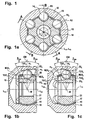
- a joint 11 comprises an outer joint part 12, an inner joint part 13, six torque-transmitting balls 14, and a ball cage 15.
- the cage has a spherical outer surface 16 which is guided in the outer joint part and a spherical inner cage surface 17 which is guided on the inner joint part, said second contact is not mandatory.
- the balls 14 are held in circumferentially distributed cage windows 18 in the ball cage 15 in a joint center plane EM.
- At the outer joint part 12 is a longitudinal axis L12
- at the inner joint part is a longitudinal axis L13.
- the intersection of the longitudinal axes L12, L13 with the joint center plane EM forms the joint center M.
- the outer joint part 12 has a bottom 19, which can for example pass into a connecting pin, and an opening 20 into which a pin connectable with the inner joint part can be inserted.
- the inner joint part 13 has an insertion opening 21.
- the position of the bottom 19 further denotes the axial direction "to the connection side”
- the position of the opening 20 further denotes the axial direction "to the opening side”.
- the ball contact angles ⁇ max / 2 are drawn in both directions for the maximum deflection angle ⁇ max of the inner joint part 13 relative to the outer joint part 12.
- the shape of the first pair of tracks 22 1 , 23 1 is taken from the section AA, the shape of the second pairs of tracks 22 2 , 22 3 the section BB.
- the first balls 14 1 have contact with first outer ball tracks 22 1 in the outer joint part and first inner ball tracks 23 1 in the inner joint part.
- the center lines M22 1 , M23 1 of these tracks are designed in the manner of UF tracks and are composed of a circular arc and a tangential connecting straight line.
- the tangents T22 1 ', T23 1 ' to the balls 14 1 in the contact points with the tracks 22 1 , 23 1 form an opening angle ⁇ 1 , which opens to the opening side.
- the second balls 14 2 are guided in outer ball tracks 22 2 in the outer joint part and inner ball tracks 23 2 in the inner joint part.
- the balls 14 2 are shown with contact in the track base of the ball tracks, which need not necessarily be given.
- the tangents T22 2 ', T23 2 ' to the balls 14 2 at the contact points with the tracks 22 2 , 23 2 form an opening angle ⁇ 2 , which opens to the connection side.
- ⁇ 2 For the description of the ball tracks 22, 23 reference is made below to the center lines M22 2 , M23 2 of the ball tracks.
- tangents T22 2 , T23 2 are drawn at the center lines, which are parallel to the aforementioned tangents T22 2 ', T23 2 '.
- the angle ⁇ 2 between said tangents T22 2 , T23 2 is between 4 and 32 °.
- each pair of tracks with its center lines M22, M23 in a radial plane R 1 , R 2 is through the joint, that these radial planes R have the same angular distance from each other and that in each case a ball 14 from a cage window 18 in the ball cage 15th is recorded.
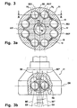
- FIGS. 2a to 2c will be described together below.
- a hinge 11 in this second embodiment comprises ball tracks 22, 23 which lie in track planes BE, BE *, which are arranged in pairs symmetrically to radial planes R through the joint.
- an angled section according to the section line AA is shown, which runs on the one hand through the web plane BE and a first pair of tracks 22 1 , 23 1 with a first ball 14 1 and the other by a radial plane between two pairs of tracks.
- a bent section is shown along the section line BB, which runs on the one hand through a web plane BE * and a second web pair with second ball tracks 22 2 , 23 2 and on the other hand through a radial plane between two web pairs.
- the circumference pairs of pairs of tracks are recognizable, each comprising a first pair of tracks 22 1 , 23 1 and a second pair of tracks 22 2 , 23 2 and which are held in a common cage window 18.
- the pitch angle of these pairs of track pairs is less than between two adjacent track pairs that do not belong to a pair of track pairs.
- First pairs of tracks and second pairs of tracks alternate in the version shown here over the circumference.
- the first balls 22 are 1 and inner tracks 23 1 14 1 performed in the first pairs of tracks from outer tracks, which are formed in the manner of webs from UF joints. That is, the center lines M22, M23 of these pairs of tracks are composed of radii and tangential straight lines connected thereto. Tangents T22 1 ', T23 1 ' to the balls in the tracks form a first opening angle ⁇ 1 , which opens to the opening side of the outer joint part.
- a second ball 14 2 can be seen , which is held in second outer ball tracks 22 2 and second inner ball tracks 23 2 .
- Tangents T22 2 ', T23 2 ' to the balls 14 2 form an opening angle ⁇ 2 with each other, which opens to the connection side of the outer joint part.
- the center lines M22 2 , M23 2 With regard to the trajectory, reference will now be made to the center lines M22 2 , M23 2 .
- tangents T22 2 , 23 2 intersect the center line M22 2 , M23 2 at the already mentioned angle ⁇ 2 .
- the track planes BE, BE * contain parallel axes PE, PE * to the longitudinal axes in smallest distance, thus forming cutting lines between the web planes and a plane perpendicular to the corresponding radial plane R1, R2 reference plane EX1, EX2.
- PE * lie track centers ME, ME * at the shortest distance to the joint center M. If four pairs of tracks symmetrically to three or four radial planes R are arranged with mutually equal pitch angle, joints with twelve or sixteen pairs of tracks 22, 23 and accordingly twelve or sixteen balls 14.
- the center ME1, ME1 * shown in the illustrations b and c is not the joint center, but the center of the path in one of the web planes BE1, BE1 *.
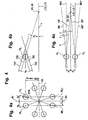
- FIG. 3a The representation a corresponds in principle to the illustration a from FIG. 2, but here a section line A-A is laid parallel to a reference plane EX1 through the balls of a pair of track pairs.
- a first reference plane EB for outer ball tracks is shown, which is perpendicular to said reference plane EX1 and contains a radial ray RS through the joint center point M.
- This reference plane EB forms with a radial plane R through the longitudinal axes L12, L13 a helix angle ⁇ .
- Parallel to the reference plane EB lie the web levels BE and BE *, in which run the center lines of the outer ball tracks of a pair of tracks.
- a first reference plane EB 'for inner ball tracks is also shown, which is also perpendicular to said reference plane EX1 and contains the radial beam RS through the joint center point M.
- This reference plane EB ' forms with the radial plane R through the longitudinal axes L12, L13 a helix angle ⁇ ' which is equal to and opposite to ⁇ .
- Parallel to the reference plane EB ' lie track planes BE', BE * 'in which the center lines of the inner ball tracks of a track pair run. The center lines of each pair of tracks intersect in the joint median plane EM.
- FIGS. 4a to 4c will be described together below.
- a is a cross section through a lying in the joint center plane ball assembly of four ball pairs 14 1 , 14 2 similar to Figure 3 shown.
- the pitch angle between the balls 14 1 , 14 2 of a ball pair and the intermediate radial plane R1 is ⁇ 0 or ⁇ 0 '.
- the ball tracks have a distance from a reference plane EX1, which corresponds to the pitch circle radius PCR multiplied by the cosine of ⁇ 0 .
- the vertical distance of the balls of a pair of balls from said radial plane R1 is denoted by a.
- the marked web levels BE 1 , BE 1 * are representative of the passage of the web levels BE, BE * of the outer ball tracks and for the passage of the web levels BE ', BE *' of the inner ball tracks through the joint center plane.
- a ball pair 14 1 , 14 2 is shown with the outer track planes EB, EB * and the inner track planes EB ', EB *'.
- the constraints D1, D2 of Brutangenten shown in illustration b are also shown.
- FIG. 5 a shows the web center line M22 of an outer ball track 22 according to one of FIGS. 1 to 3 which runs parallel to a web base line.
- the center line M22 of a web in the outer part is composed of a first radius R1 about a center M1 with the first axial offset O1a and a radial offset O1r and a second radius R2 with a second axial offset O2a and a second radial offset O2r.
- the transition is indicated by a turning point W22.
- the second radius R2 is adjoined tangentially by a straight line G3 parallel to the axis L12, PE, PE *.
- the tangent T22 is drawn on the center line M22, which intersects a longitudinal axis L12, PE, PE * at the angle ⁇ / 2.
- a perpendicular on the tangent T22 intersects the longitudinal axis L12, PE;
- Another reference radius RZ is plotted around the center of the track M, ME Left of the median plane EM towards the terminal side 19, the median line M22 extends within the radius RB and outside the radius RZ of the median plane EM towards the opening side 20, the center line M22 extends substantially outside the radius R.
- the radial ball movement of a ball on its way along the ball track with respect to the track center M, ME is denoted by e. where a safety margin is required to avoid edge bearers.
- FIG. 5b shows the web center lines M23 of the associated inner ball tracks 23, which run parallel to the web base lines, according to one of FIGS. 1 to 3.
- the center line M23 of a path 23 in the inner cell 13 is composed of a first radius R1 'around a center M1' and a second radius R2 'around a center M2'. The transition is indicated by a turning point W23.
- the second radius R2 ' is adjoined by a straight line G3' parallel to the axis L13, PE *, PE *, PE ', PE *'.
- the center M1 ' has an axial offset O1a 'and a radial offset O1r' and the center M2 'an axial offset O2a' and a radial offset O2r '.
- the tangent T23 is drawn on the center line M23, which intersects a longitudinal axis L13, PE, PE *, PE ', PE *' at the angle ⁇ / 2.
- a perpendicular on the tangent T23 intersects the longitudinal axis L13, PE; PE *, PE ', PE *' in the reference center MB ', MBE' of a reference radius RB '.
- Another reference radius RZ ' is plotted around the web center M, ME.
- the center line M23 extends within the radius RB 'and outside the radius RZ'. Left of the center plane EM to the connection side 19 toward the center line M23 extends at least predominantly outside the radius RB '.
- the radial ball movement of a ball on its way along the ball track with respect to the track center M, ME is denoted by e.
- the two center lines M22, M23 of Figures 5a, 5b intersect in the joint center plane EM at the angle ⁇ and are mirror-symmetrical to this center plane.
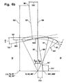
- the web centerline M22 of an outer ball track 22, which runs parallel to a web base line, is shown in a modified embodiment.
- the center line M22 of a web in the outer part consists of a first radius R1 about a center M1 with the first axial offset O1a and a radial offset O1r and a second radius R2 with a second axial offset 02a and a second radial offset O2r and a third radius R3, which is opposite to the radius R2 to the radius R1, smaller than this radius R1 and is curved in the same sense, the position of its center M3 is not measured closer together.
- the transition between the first and second radius is indicated by a turning point W22.
- the second radius R2 is adjoined tangentially by a straight line G3 parallel to the axis L12, PE, PE *.
- the tangent T22 and the center line M22 is shown, which intersects a longitudinal axis L12, PE, PE * at the angle ⁇ / 2.
- a perpendicular on the tangent T22 intersects the longitudinal axis L12, PE; PE * in the reference center MB, MBE of a reference radius RB.
- Another reference radius is plotted around the track center M, ME. Left of the median plane to the terminal side 19 towards the center line M22 extends within the radius RB and outside the radius RZ.
- the center line M22 runs predominantly outside of the radius RB.
- the radial ball movement of a ball on its way along the ball track with respect to the track center M, ME is denoted by e. This corresponds to the minimum thickness of the ball cage in the area of the cage windows, with a safety margin being required to avoid edge beams.
- FIG. 6b shows the web centerlines M23 of the associated inner ball tracks 23 running parallel to the web baselines in a modified embodiment.
- the center line M23 of a track 23 in the inner part 13 is composed of a first radius R1 'about a center M1', a second radius R2 'about a center M2' and a third radius R3 'opposite to the radius R2' at the radius R1 ', smaller than this radius R1, is curved and, in the same sense, curved together.
- the second radius R2 ' is adjoined by a straight line G3' parallel to the axis L13, PE *, PE *, PE ', PE *'.
- the center M1 ' has an axial offset O1a' and a radial offset O1r '
- the center M2' has an axial offset O2a 'and a radial offset O2r'.
- the position of the center M3 ' is not measured in detail.
- the tangent T23 is drawn on the center line M23, which intersects a longitudinal axis L13, PE, PE *, PE ', PE *' at the angle ⁇ / 2.
- a perpendicular on the tangent T23 intersects the longitudinal axis L12, PE; PE *, PE '; PE * 'in the reference center MB', MBE 'of a reference radius RB'.
- Another reference radius RZ ' is plotted around the web center M, ME.
- the center line M23 extends within the radius RB 'and outside the radius RZ'.
- the center line M23 extends predominantly outside the radius RB '.
- the radial ball movement of a ball on its way along the ball track with respect to the track center M, ME is denoted by e.
- the two center lines M22, M23 of Figures 6a, 6b intersect in the joint center plane EM at the angle ⁇ and are mirror-symmetrical to this center plane.
Landscapes
- Engineering & Computer Science (AREA)
- General Engineering & Computer Science (AREA)
- Mechanical Engineering (AREA)
- Pivots And Pivotal Connections (AREA)
- Vehicle Body Suspensions (AREA)
- Rolling Contact Bearings (AREA)
- Toys (AREA)
- Spinning Or Twisting Of Yarns (AREA)
- Steroid Compounds (AREA)
- Earth Drilling (AREA)
- Hinges (AREA)
Applications Claiming Priority (3)
| Application Number | Priority Date | Filing Date | Title |
|---|---|---|---|
| DE10338719 | 2003-08-22 | ||
| DE102004018777A DE102004018777A1 (de) | 2003-08-22 | 2004-04-19 | Gegenbahngelenk für grosse Beugewinkel |
| PCT/EP2004/006088 WO2005028895A1 (de) | 2003-08-22 | 2004-06-05 | Gegenbahngelenk für grosse beugewinkel |
Publications (2)
| Publication Number | Publication Date |
|---|---|
| EP1656509A1 EP1656509A1 (de) | 2006-05-17 |
| EP1656509B1 true EP1656509B1 (de) | 2007-10-31 |
Family
ID=34379058
Family Applications (1)
| Application Number | Title | Priority Date | Filing Date |
|---|---|---|---|
| EP04736174A Expired - Lifetime EP1656509B1 (de) | 2003-08-22 | 2004-06-05 | Gegenbahngelenk für grosse beugewinkel |
Country Status (8)
| Country | Link |
|---|---|
| US (2) | US7632189B2 (enExample) |
| EP (1) | EP1656509B1 (enExample) |
| JP (1) | JP4518424B2 (enExample) |
| AT (1) | ATE377160T1 (enExample) |
| BR (1) | BRPI0413841B1 (enExample) |
| DE (1) | DE502004005377D1 (enExample) |
| RU (1) | RU2324084C2 (enExample) |
| WO (1) | WO2005028895A1 (enExample) |
Cited By (1)
| Publication number | Priority date | Publication date | Assignee | Title |
|---|---|---|---|---|
| WO2013029655A1 (en) | 2011-08-29 | 2013-03-07 | Gkn Driveline International Gmbh | Counter track joint |
Families Citing this family (18)
| Publication number | Priority date | Publication date | Assignee | Title |
|---|---|---|---|---|
| DE202004021765U1 (de) * | 2004-11-02 | 2010-10-14 | Gkn Driveline International Gmbh | Gegenbahngelenk mit Bahnwendepunkt |
| EP1881218A4 (en) * | 2005-05-12 | 2009-03-04 | Ntn Toyo Bearing Co Ltd | UNIVERSAL JOINT WITH CONSTANT SPEED OF FIXED TYPE |
| CN101578458B (zh) * | 2006-10-10 | 2015-01-28 | Ifa技术有限责任公司 | 等速滑动接头 |
| DE102007010352A1 (de) | 2006-10-10 | 2008-04-17 | Ifa-Technologies Gmbh | Homokinetisches Verschiebegelenk |
| CN101542149B (zh) * | 2006-10-13 | 2013-10-16 | Gkn动力传动系统国际有限责任公司 | 呈相对滚道接头形式的等速球形接头 |
| JP5183930B2 (ja) * | 2007-02-02 | 2013-04-17 | Ntn株式会社 | 固定式等速自在継手 |
| US8690690B2 (en) | 2010-06-30 | 2014-04-08 | American Axle & Manufacturing, Inc. | Constant velocity joint with quick connector and method |
| KR101345903B1 (ko) | 2011-11-21 | 2013-12-30 | 현대위아 주식회사 | 차량용 슬라이드식 볼타입 등속조인트 |
| KR101378677B1 (ko) | 2012-06-18 | 2014-03-27 | 현대위아 주식회사 | 차량의 슬라이드식 볼타입 등속조인트 |
| KR101314447B1 (ko) | 2012-06-18 | 2013-10-14 | 현대위아 주식회사 | 자동차용 슬라이드식 볼타입 등속조인트 |
| DE102012110276A1 (de) * | 2012-10-26 | 2014-04-30 | Thyssenkrupp Steel Europe Ag | Leichtbaugelenk für die Übertragung von Drehbewegungen |
| KR20160102636A (ko) * | 2015-02-23 | 2016-08-31 | 이래오토모티브시스템 주식회사 | 고정형 등속 조인트 |
| KR20180071707A (ko) | 2016-12-20 | 2018-06-28 | 이래에이엠에스 주식회사 | 고정형 등속 조인트 |
| US12234864B2 (en) | 2018-06-15 | 2025-02-25 | Steering Solutions Ip Holding Corporation | Constant velocity joint with asymmetric opposed tracks |
| DE102019105195A1 (de) * | 2019-02-28 | 2020-09-03 | Neapco Intellectual Property Holdings, Llc | Gleichlaufdrehgelenk |
| CN116292659B (zh) * | 2023-02-02 | 2025-08-12 | 上海纳铁福传动系统有限公司 | 一种移动球笼万向节 |
| KR102770429B1 (ko) * | 2024-02-23 | 2025-02-20 | 이래에이엠에스 주식회사 | 등속조인트 |
| KR102770430B1 (ko) * | 2024-02-23 | 2025-02-20 | 이래에이엠에스 주식회사 | 등속조인트 |
Family Cites Families (25)
| Publication number | Priority date | Publication date | Assignee | Title |
|---|---|---|---|---|
| US3553979A (en) | 1967-12-31 | 1971-01-12 | Toyota Motor Co Ltd | Universal joint of uniform speed |
| JPS5220625B1 (enExample) | 1968-06-27 | 1977-06-04 | ||
| JPS60129519U (ja) * | 1984-02-10 | 1985-08-30 | エヌ・テ−・エヌ東洋ベアリング株式会社 | 等速自在継手 |
| DE3739867A1 (de) | 1987-11-25 | 1989-06-08 | Uni Cardan Ag | Gleichlaufdrehgelenk |
| JPH0736184Y2 (ja) * | 1987-12-21 | 1995-08-16 | 日産自動車株式会社 | 等速自在継手 |
| DE3939531C1 (enExample) * | 1989-11-30 | 1991-06-06 | Loehr & Bromkamp Gmbh, 6050 Offenbach, De | |
| US5509857A (en) * | 1993-12-17 | 1996-04-23 | General Motors Corporation | Constant velocity universal joint |
| JPH07317791A (ja) | 1994-03-30 | 1995-12-08 | Toyoda Mach Works Ltd | 等速ジョイント |
| DE4440285C1 (de) * | 1994-11-11 | 1996-04-25 | Loehr & Bromkamp Gmbh | Kugelgleichlaufdrehgelenk |
| EP0717209A1 (en) * | 1994-12-14 | 1996-06-19 | General Motors Corporation | Stroking constant velocity universal joint |
| JP3505020B2 (ja) * | 1995-12-26 | 2004-03-08 | Ntn株式会社 | 固定型等速自在継手 |
| DE19706864C1 (de) * | 1997-02-21 | 1998-06-25 | Loehr & Bromkamp Gmbh | Gleichlaufdrehgelenk |
| DE19751493C1 (de) * | 1997-11-20 | 1999-07-22 | Gkn Loebro Gmbh | Gleichlauffestgelenk mit Steuerelement |
| US6227979B1 (en) * | 1998-02-20 | 2001-05-08 | Toyota Jidosha Kabushiki Kaisha | Constant velocity universal joint |
| JP3941214B2 (ja) * | 1998-04-15 | 2007-07-04 | 日本精工株式会社 | 等速ジョイント |
| DE19831014C2 (de) * | 1998-07-10 | 2000-06-29 | Gkn Loebro Gmbh | Gleichlauffestgelenk mit zwei Sätzen von gegenläufigen Laufrillen |
| DE19905451C2 (de) | 1999-02-10 | 2001-03-08 | Gkn Loebro Gmbh | Gleichlaufgelenk |
| FR2799519A1 (fr) * | 1999-10-08 | 2001-04-13 | Pierre Guimbretiere | Joint homocinetique fixe a billes |
| DE19963617C1 (de) * | 1999-12-30 | 2001-12-13 | Gkn Automotive Gmbh | Gleichlauffestgelenke/Käfigmontage in ein Gelenkaußenteil |
| EP1264114B1 (en) * | 2000-02-16 | 2009-04-22 | Delphi Technologies, Inc. | Constant velocity joint having fixed centre and crossed grooves |
| DE10033491C2 (de) | 2000-07-10 | 2003-11-20 | Gkn Loebro Gmbh | Kugelgleichlauffestgelenk mit Kugelpaaren, deren Bahnen in symmetrischen Ebenen liegen |
| DE10060220C2 (de) * | 2000-12-04 | 2002-11-28 | Gkn Automotive Gmbh | Gleichlauffestgelenk |
| DE10148297B4 (de) | 2001-09-29 | 2008-03-27 | Gkn Driveline Deutschland Gmbh | Kugelgleichlaufdrehgelenk |
| DE10337612B4 (de) * | 2002-11-15 | 2009-11-05 | Gkn Driveline International Gmbh | Gegenbahngelenk mit Steuerwinkelumkehr |
| DE10337918B4 (de) | 2003-08-18 | 2010-01-07 | Gkn Driveline Deutschland Gmbh | Twin-Ball-Gelenk mit verbessertem Kugelkäfig |
-
2004
- 2004-06-05 EP EP04736174A patent/EP1656509B1/de not_active Expired - Lifetime
- 2004-06-05 AT AT04736174T patent/ATE377160T1/de not_active IP Right Cessation
- 2004-06-05 RU RU2006109015/11A patent/RU2324084C2/ru active
- 2004-06-05 JP JP2006524230A patent/JP4518424B2/ja not_active Expired - Fee Related
- 2004-06-05 US US10/568,896 patent/US7632189B2/en not_active Expired - Fee Related
- 2004-06-05 DE DE502004005377T patent/DE502004005377D1/de not_active Expired - Lifetime
- 2004-06-05 WO PCT/EP2004/006088 patent/WO2005028895A1/de not_active Ceased
- 2004-06-05 BR BRPI0413841-4A patent/BRPI0413841B1/pt not_active IP Right Cessation
-
2009
- 2009-10-08 US US12/575,897 patent/US7854658B2/en not_active Expired - Fee Related
Cited By (1)
| Publication number | Priority date | Publication date | Assignee | Title |
|---|---|---|---|---|
| WO2013029655A1 (en) | 2011-08-29 | 2013-03-07 | Gkn Driveline International Gmbh | Counter track joint |
Also Published As
| Publication number | Publication date |
|---|---|
| BRPI0413841A (pt) | 2006-11-21 |
| US7854658B2 (en) | 2010-12-21 |
| JP2007503555A (ja) | 2007-02-22 |
| WO2005028895A1 (de) | 2005-03-31 |
| DE502004005377D1 (de) | 2007-12-13 |
| US20100029395A1 (en) | 2010-02-04 |
| BRPI0413841B1 (pt) | 2018-01-09 |
| US20060281565A1 (en) | 2006-12-14 |
| EP1656509A1 (de) | 2006-05-17 |
| JP4518424B2 (ja) | 2010-08-04 |
| ATE377160T1 (de) | 2007-11-15 |
| RU2006109015A (ru) | 2007-10-20 |
| US7632189B2 (en) | 2009-12-15 |
| RU2324084C2 (ru) | 2008-05-10 |
Similar Documents
| Publication | Publication Date | Title |
|---|---|---|
| EP1656509B1 (de) | Gegenbahngelenk für grosse beugewinkel | |
| DE10060120B4 (de) | Kugelgleichlaufgelenk als Gegenbahngelenk | |
| DE102004018777A1 (de) | Gegenbahngelenk für grosse Beugewinkel | |
| DE10337612B4 (de) | Gegenbahngelenk mit Steuerwinkelumkehr | |
| DE19706864C1 (de) | Gleichlaufdrehgelenk | |
| EP2239477B1 (de) | Gegenbahngelenk mit Bahnwendepunkt | |
| DE10060220C2 (de) | Gleichlauffestgelenk | |
| DE19704761A1 (de) | Kugelgleichlaufdrehgelenk | |
| DE4440285C1 (de) | Kugelgleichlaufdrehgelenk | |
| DE102004006225B4 (de) | Gleichlaufgelenk mit geringer Radialbewegung der Kugeln | |
| DE10060117C2 (de) | Kugelgleichlauffestgelenk als Gegenbahngelenk | |
| DE102013103155B4 (de) | Gleichlaufgelenk in Form eines Gegenbahngelenks | |
| DE102005042909B4 (de) | Gegenbahngelenk mit begrenzter Axialverschiebung | |
| DE102012102678A1 (de) | Gleichlaufgelenk | |
| EP3818276B1 (de) | Gleichlaufgelenk | |
| DE19507859C2 (de) | Gleichlaufdrehgelenk in VL-Bauart mit gekrümmtem Bahnverlauf | |
| EP1966500B1 (de) | Kugelgleichlauffestgelenk mit grossem beugewinkel | |
| DE102004018721B4 (de) | Kugelfestgelenk mit gedrehten Bahnquerschnitten | |
| WO2003046397A1 (de) | Kugelkäfig für axial zu verbauende kugelgleichlaufdrehgelenke | |
| DE112006004069T5 (de) | Gleichlaufgelenk nach Art eines Gegenbahngelenkes | |
| DE19633216C1 (de) | Kugelgleichlaufdrehgelenke mit verbesserter Kugelsteuerung | |
| WO2005028896A1 (de) | Kugelfestgelenk mit gedrehten bahnquerschnitten | |
| WO2005028894A1 (de) | Gleichlaufgelenk mit geringer radialbewegung der kugeln | |
| DE19613462C2 (de) | Gelenkverbindung zur Drehübertragung | |
| DE424819C (de) | Bewegliche Kupplung |
Legal Events
| Date | Code | Title | Description |
|---|---|---|---|
| PUAI | Public reference made under article 153(3) epc to a published international application that has entered the european phase |
Free format text: ORIGINAL CODE: 0009012 |
|
| 17P | Request for examination filed |
Effective date: 20060218 |
|
| AK | Designated contracting states |
Kind code of ref document: A1 Designated state(s): AT BE BG CH CY CZ DE DK EE ES FI FR GB GR HU IE IT LI LU MC NL PL PT RO SE SI SK TR |
|
| DAX | Request for extension of the european patent (deleted) | ||
| GRAP | Despatch of communication of intention to grant a patent |
Free format text: ORIGINAL CODE: EPIDOSNIGR1 |
|
| GRAS | Grant fee paid |
Free format text: ORIGINAL CODE: EPIDOSNIGR3 |
|
| GRAA | (expected) grant |
Free format text: ORIGINAL CODE: 0009210 |
|
| AK | Designated contracting states |
Kind code of ref document: B1 Designated state(s): AT BE BG CH CY CZ DE DK EE ES FI FR GB GR HU IE IT LI LU MC NL PL PT RO SE SI SK TR |
|
| REG | Reference to a national code |
Ref country code: GB Ref legal event code: FG4D Free format text: NOT ENGLISH |
|
| REG | Reference to a national code |
Ref country code: IE Ref legal event code: FG4D Free format text: LANGUAGE OF EP DOCUMENT: GERMAN |
|
| REG | Reference to a national code |
Ref country code: CH Ref legal event code: EP |
|
| REF | Corresponds to: |
Ref document number: 502004005377 Country of ref document: DE Date of ref document: 20071213 Kind code of ref document: P |
|
| NLV1 | Nl: lapsed or annulled due to failure to fulfill the requirements of art. 29p and 29m of the patents act | ||
| PG25 | Lapsed in a contracting state [announced via postgrant information from national office to epo] |
Ref country code: SE Free format text: LAPSE BECAUSE OF FAILURE TO SUBMIT A TRANSLATION OF THE DESCRIPTION OR TO PAY THE FEE WITHIN THE PRESCRIBED TIME-LIMIT Effective date: 20080131 Ref country code: ES Free format text: LAPSE BECAUSE OF FAILURE TO SUBMIT A TRANSLATION OF THE DESCRIPTION OR TO PAY THE FEE WITHIN THE PRESCRIBED TIME-LIMIT Effective date: 20080211 Ref country code: NL Free format text: LAPSE BECAUSE OF FAILURE TO SUBMIT A TRANSLATION OF THE DESCRIPTION OR TO PAY THE FEE WITHIN THE PRESCRIBED TIME-LIMIT Effective date: 20071031 |
|
| GBV | Gb: ep patent (uk) treated as always having been void in accordance with gb section 77(7)/1977 [no translation filed] | ||
| PG25 | Lapsed in a contracting state [announced via postgrant information from national office to epo] |
Ref country code: PL Free format text: LAPSE BECAUSE OF FAILURE TO SUBMIT A TRANSLATION OF THE DESCRIPTION OR TO PAY THE FEE WITHIN THE PRESCRIBED TIME-LIMIT Effective date: 20071031 Ref country code: SI Free format text: LAPSE BECAUSE OF FAILURE TO SUBMIT A TRANSLATION OF THE DESCRIPTION OR TO PAY THE FEE WITHIN THE PRESCRIBED TIME-LIMIT Effective date: 20071031 Ref country code: BG Free format text: LAPSE BECAUSE OF FAILURE TO SUBMIT A TRANSLATION OF THE DESCRIPTION OR TO PAY THE FEE WITHIN THE PRESCRIBED TIME-LIMIT Effective date: 20080131 Ref country code: PT Free format text: LAPSE BECAUSE OF FAILURE TO SUBMIT A TRANSLATION OF THE DESCRIPTION OR TO PAY THE FEE WITHIN THE PRESCRIBED TIME-LIMIT Effective date: 20080331 |
|
| REG | Reference to a national code |
Ref country code: IE Ref legal event code: FD4D |
|
| ET | Fr: translation filed | ||
| PG25 | Lapsed in a contracting state [announced via postgrant information from national office to epo] |
Ref country code: CZ Free format text: LAPSE BECAUSE OF FAILURE TO SUBMIT A TRANSLATION OF THE DESCRIPTION OR TO PAY THE FEE WITHIN THE PRESCRIBED TIME-LIMIT Effective date: 20071031 Ref country code: DK Free format text: LAPSE BECAUSE OF FAILURE TO SUBMIT A TRANSLATION OF THE DESCRIPTION OR TO PAY THE FEE WITHIN THE PRESCRIBED TIME-LIMIT Effective date: 20071031 |
|
| PG25 | Lapsed in a contracting state [announced via postgrant information from national office to epo] |
Ref country code: RO Free format text: LAPSE BECAUSE OF FAILURE TO SUBMIT A TRANSLATION OF THE DESCRIPTION OR TO PAY THE FEE WITHIN THE PRESCRIBED TIME-LIMIT Effective date: 20071031 Ref country code: SK Free format text: LAPSE BECAUSE OF FAILURE TO SUBMIT A TRANSLATION OF THE DESCRIPTION OR TO PAY THE FEE WITHIN THE PRESCRIBED TIME-LIMIT Effective date: 20071031 |
|
| PLBE | No opposition filed within time limit |
Free format text: ORIGINAL CODE: 0009261 |
|
| STAA | Information on the status of an ep patent application or granted ep patent |
Free format text: STATUS: NO OPPOSITION FILED WITHIN TIME LIMIT |
|
| 26N | No opposition filed |
Effective date: 20080801 |
|
| PG25 | Lapsed in a contracting state [announced via postgrant information from national office to epo] |
Ref country code: IE Free format text: LAPSE BECAUSE OF FAILURE TO SUBMIT A TRANSLATION OF THE DESCRIPTION OR TO PAY THE FEE WITHIN THE PRESCRIBED TIME-LIMIT Effective date: 20071031 |
|
| PG25 | Lapsed in a contracting state [announced via postgrant information from national office to epo] |
Ref country code: GB Free format text: LAPSE BECAUSE OF FAILURE TO SUBMIT A TRANSLATION OF THE DESCRIPTION OR TO PAY THE FEE WITHIN THE PRESCRIBED TIME-LIMIT Effective date: 20071031 |
|
| BERE | Be: lapsed |
Owner name: GKN DRIVELINE DEUTSCHLAND G.M.B.H. Effective date: 20080630 |
|
| PG25 | Lapsed in a contracting state [announced via postgrant information from national office to epo] |
Ref country code: MC Free format text: LAPSE BECAUSE OF NON-PAYMENT OF DUE FEES Effective date: 20080630 Ref country code: GR Free format text: LAPSE BECAUSE OF FAILURE TO SUBMIT A TRANSLATION OF THE DESCRIPTION OR TO PAY THE FEE WITHIN THE PRESCRIBED TIME-LIMIT Effective date: 20080201 |
|
| REG | Reference to a national code |
Ref country code: CH Ref legal event code: PL |
|
| PG25 | Lapsed in a contracting state [announced via postgrant information from national office to epo] |
Ref country code: FI Free format text: LAPSE BECAUSE OF FAILURE TO SUBMIT A TRANSLATION OF THE DESCRIPTION OR TO PAY THE FEE WITHIN THE PRESCRIBED TIME-LIMIT Effective date: 20071031 |
|
| PG25 | Lapsed in a contracting state [announced via postgrant information from national office to epo] |
Ref country code: BE Free format text: LAPSE BECAUSE OF NON-PAYMENT OF DUE FEES Effective date: 20080630 |
|
| PG25 | Lapsed in a contracting state [announced via postgrant information from national office to epo] |
Ref country code: EE Free format text: LAPSE BECAUSE OF FAILURE TO SUBMIT A TRANSLATION OF THE DESCRIPTION OR TO PAY THE FEE WITHIN THE PRESCRIBED TIME-LIMIT Effective date: 20071031 |
|
| PG25 | Lapsed in a contracting state [announced via postgrant information from national office to epo] |
Ref country code: LI Free format text: LAPSE BECAUSE OF NON-PAYMENT OF DUE FEES Effective date: 20080630 Ref country code: CH Free format text: LAPSE BECAUSE OF NON-PAYMENT OF DUE FEES Effective date: 20080630 |
|
| PG25 | Lapsed in a contracting state [announced via postgrant information from national office to epo] |
Ref country code: CY Free format text: LAPSE BECAUSE OF FAILURE TO SUBMIT A TRANSLATION OF THE DESCRIPTION OR TO PAY THE FEE WITHIN THE PRESCRIBED TIME-LIMIT Effective date: 20071031 |
|
| PG25 | Lapsed in a contracting state [announced via postgrant information from national office to epo] |
Ref country code: AT Free format text: LAPSE BECAUSE OF NON-PAYMENT OF DUE FEES Effective date: 20080605 |
|
| PG25 | Lapsed in a contracting state [announced via postgrant information from national office to epo] |
Ref country code: HU Free format text: LAPSE BECAUSE OF FAILURE TO SUBMIT A TRANSLATION OF THE DESCRIPTION OR TO PAY THE FEE WITHIN THE PRESCRIBED TIME-LIMIT Effective date: 20080501 Ref country code: LU Free format text: LAPSE BECAUSE OF NON-PAYMENT OF DUE FEES Effective date: 20080605 |
|
| PG25 | Lapsed in a contracting state [announced via postgrant information from national office to epo] |
Ref country code: TR Free format text: LAPSE BECAUSE OF FAILURE TO SUBMIT A TRANSLATION OF THE DESCRIPTION OR TO PAY THE FEE WITHIN THE PRESCRIBED TIME-LIMIT Effective date: 20071031 |
|
| PG25 | Lapsed in a contracting state [announced via postgrant information from national office to epo] |
Ref country code: IT Free format text: LAPSE BECAUSE OF NON-PAYMENT OF DUE FEES Effective date: 20080630 |
|
| REG | Reference to a national code |
Ref country code: FR Ref legal event code: PLFP Year of fee payment: 13 |
|
| REG | Reference to a national code |
Ref country code: FR Ref legal event code: PLFP Year of fee payment: 14 |
|
| REG | Reference to a national code |
Ref country code: FR Ref legal event code: PLFP Year of fee payment: 15 |
|
| PGFP | Annual fee paid to national office [announced via postgrant information from national office to epo] |
Ref country code: FR Payment date: 20200623 Year of fee payment: 17 |
|
| PG25 | Lapsed in a contracting state [announced via postgrant information from national office to epo] |
Ref country code: FR Free format text: LAPSE BECAUSE OF NON-PAYMENT OF DUE FEES Effective date: 20210630 |
|
| PGFP | Annual fee paid to national office [announced via postgrant information from national office to epo] |
Ref country code: DE Payment date: 20230620 Year of fee payment: 20 |
|
| REG | Reference to a national code |
Ref country code: DE Ref legal event code: R071 Ref document number: 502004005377 Country of ref document: DE |