EP1656234B1 - Tete de balayage faisant partie d'un dispositif de forage et de decoupe laser - Google Patents
Tete de balayage faisant partie d'un dispositif de forage et de decoupe laser Download PDFInfo
- Publication number
- EP1656234B1 EP1656234B1 EP05783447A EP05783447A EP1656234B1 EP 1656234 B1 EP1656234 B1 EP 1656234B1 EP 05783447 A EP05783447 A EP 05783447A EP 05783447 A EP05783447 A EP 05783447A EP 1656234 B1 EP1656234 B1 EP 1656234B1
- Authority
- EP
- European Patent Office
- Prior art keywords
- unit
- scan head
- head according
- laser
- scan
- Prior art date
- Legal status (The legal status is an assumption and is not a legal conclusion. Google has not performed a legal analysis and makes no representation as to the accuracy of the status listed.)
- Active
Links
- 238000005520 cutting process Methods 0.000 title claims description 27
- 238000005553 drilling Methods 0.000 title claims description 23
- 230000003287 optical effect Effects 0.000 claims description 58
- 230000004075 alteration Effects 0.000 claims description 17
- 238000012360 testing method Methods 0.000 claims description 12
- 230000005855 radiation Effects 0.000 claims description 11
- 230000008878 coupling Effects 0.000 claims description 10
- 238000010168 coupling process Methods 0.000 claims description 10
- 238000005859 coupling reaction Methods 0.000 claims description 10
- 238000006073 displacement reaction Methods 0.000 claims description 9
- 206010010071 Coma Diseases 0.000 claims description 6
- 238000010521 absorption reaction Methods 0.000 claims description 6
- 230000015572 biosynthetic process Effects 0.000 claims description 4
- 238000012937 correction Methods 0.000 claims description 3
- 238000007689 inspection Methods 0.000 claims 4
- 230000010287 polarization Effects 0.000 description 41
- 238000012545 processing Methods 0.000 description 8
- 238000013016 damping Methods 0.000 description 7
- 230000033001 locomotion Effects 0.000 description 7
- 230000008859 change Effects 0.000 description 6
- 230000000694 effects Effects 0.000 description 6
- 238000003698 laser cutting Methods 0.000 description 6
- 239000000463 material Substances 0.000 description 6
- 238000000034 method Methods 0.000 description 6
- 230000005540 biological transmission Effects 0.000 description 5
- 230000001419 dependent effect Effects 0.000 description 4
- 238000003384 imaging method Methods 0.000 description 4
- 230000008569 process Effects 0.000 description 4
- 230000004044 response Effects 0.000 description 4
- 238000000576 coating method Methods 0.000 description 3
- 238000009826 distribution Methods 0.000 description 3
- 238000003754 machining Methods 0.000 description 3
- 230000033228 biological regulation Effects 0.000 description 2
- 239000013078 crystal Substances 0.000 description 2
- 238000013461 design Methods 0.000 description 2
- 238000011161 development Methods 0.000 description 2
- 230000018109 developmental process Effects 0.000 description 2
- 230000003993 interaction Effects 0.000 description 2
- 238000012544 monitoring process Methods 0.000 description 2
- 230000001681 protective effect Effects 0.000 description 2
- 230000000007 visual effect Effects 0.000 description 2
- 206010073261 Ovarian theca cell tumour Diseases 0.000 description 1
- 229910000831 Steel Inorganic materials 0.000 description 1
- 230000009471 action Effects 0.000 description 1
- 238000007792 addition Methods 0.000 description 1
- 239000006117 anti-reflective coating Substances 0.000 description 1
- 230000015556 catabolic process Effects 0.000 description 1
- 239000003518 caustics Substances 0.000 description 1
- 239000011248 coating agent Substances 0.000 description 1
- 239000012141 concentrate Substances 0.000 description 1
- 238000010276 construction Methods 0.000 description 1
- 238000001816 cooling Methods 0.000 description 1
- 238000001514 detection method Methods 0.000 description 1
- 238000010586 diagram Methods 0.000 description 1
- 230000005684 electric field Effects 0.000 description 1
- 238000005516 engineering process Methods 0.000 description 1
- 230000005484 gravity Effects 0.000 description 1
- 238000010438 heat treatment Methods 0.000 description 1
- 230000001771 impaired effect Effects 0.000 description 1
- 238000012886 linear function Methods 0.000 description 1
- 238000004519 manufacturing process Methods 0.000 description 1
- 239000007769 metal material Substances 0.000 description 1
- 238000012986 modification Methods 0.000 description 1
- 230000004048 modification Effects 0.000 description 1
- 239000005304 optical glass Substances 0.000 description 1
- 238000012634 optical imaging Methods 0.000 description 1
- 230000003647 oxidation Effects 0.000 description 1
- 238000007254 oxidation reaction Methods 0.000 description 1
- 230000010363 phase shift Effects 0.000 description 1
- 230000000704 physical effect Effects 0.000 description 1
- 230000006798 recombination Effects 0.000 description 1
- 238000005215 recombination Methods 0.000 description 1
- 238000002310 reflectometry Methods 0.000 description 1
- 230000001105 regulatory effect Effects 0.000 description 1
- 238000009877 rendering Methods 0.000 description 1
- 238000001228 spectrum Methods 0.000 description 1
- 239000010959 steel Substances 0.000 description 1
- 238000000859 sublimation Methods 0.000 description 1
- 230000008022 sublimation Effects 0.000 description 1
- 208000001644 thecoma Diseases 0.000 description 1
- 238000011144 upstream manufacturing Methods 0.000 description 1
Images


Classifications
-
- B—PERFORMING OPERATIONS; TRANSPORTING
- B23—MACHINE TOOLS; METAL-WORKING NOT OTHERWISE PROVIDED FOR
- B23K—SOLDERING OR UNSOLDERING; WELDING; CLADDING OR PLATING BY SOLDERING OR WELDING; CUTTING BY APPLYING HEAT LOCALLY, e.g. FLAME CUTTING; WORKING BY LASER BEAM
- B23K26/00—Working by laser beam, e.g. welding, cutting or boring
- B23K26/02—Positioning or observing the workpiece, e.g. with respect to the point of impact; Aligning, aiming or focusing the laser beam
- B23K26/03—Observing, e.g. monitoring, the workpiece
- B23K26/032—Observing, e.g. monitoring, the workpiece using optical means
-
- B—PERFORMING OPERATIONS; TRANSPORTING
- B23—MACHINE TOOLS; METAL-WORKING NOT OTHERWISE PROVIDED FOR
- B23K—SOLDERING OR UNSOLDERING; WELDING; CLADDING OR PLATING BY SOLDERING OR WELDING; CUTTING BY APPLYING HEAT LOCALLY, e.g. FLAME CUTTING; WORKING BY LASER BEAM
- B23K26/00—Working by laser beam, e.g. welding, cutting or boring
- B23K26/02—Positioning or observing the workpiece, e.g. with respect to the point of impact; Aligning, aiming or focusing the laser beam
- B23K26/06—Shaping the laser beam, e.g. by masks or multi-focusing
- B23K26/064—Shaping the laser beam, e.g. by masks or multi-focusing by means of optical elements, e.g. lenses, mirrors or prisms
- B23K26/0648—Shaping the laser beam, e.g. by masks or multi-focusing by means of optical elements, e.g. lenses, mirrors or prisms comprising lenses
-
- B—PERFORMING OPERATIONS; TRANSPORTING
- B23—MACHINE TOOLS; METAL-WORKING NOT OTHERWISE PROVIDED FOR
- B23K—SOLDERING OR UNSOLDERING; WELDING; CLADDING OR PLATING BY SOLDERING OR WELDING; CUTTING BY APPLYING HEAT LOCALLY, e.g. FLAME CUTTING; WORKING BY LASER BEAM
- B23K26/00—Working by laser beam, e.g. welding, cutting or boring
- B23K26/02—Positioning or observing the workpiece, e.g. with respect to the point of impact; Aligning, aiming or focusing the laser beam
- B23K26/06—Shaping the laser beam, e.g. by masks or multi-focusing
- B23K26/0665—Shaping the laser beam, e.g. by masks or multi-focusing by beam condensation on the workpiece, e.g. for focusing
-
- B—PERFORMING OPERATIONS; TRANSPORTING
- B23—MACHINE TOOLS; METAL-WORKING NOT OTHERWISE PROVIDED FOR
- B23K—SOLDERING OR UNSOLDERING; WELDING; CLADDING OR PLATING BY SOLDERING OR WELDING; CUTTING BY APPLYING HEAT LOCALLY, e.g. FLAME CUTTING; WORKING BY LASER BEAM
- B23K26/00—Working by laser beam, e.g. welding, cutting or boring
- B23K26/12—Working by laser beam, e.g. welding, cutting or boring in a special atmosphere, e.g. in an enclosure
- B23K26/123—Working by laser beam, e.g. welding, cutting or boring in a special atmosphere, e.g. in an enclosure in an atmosphere of particular gases
-
- B—PERFORMING OPERATIONS; TRANSPORTING
- B23—MACHINE TOOLS; METAL-WORKING NOT OTHERWISE PROVIDED FOR
- B23K—SOLDERING OR UNSOLDERING; WELDING; CLADDING OR PLATING BY SOLDERING OR WELDING; CUTTING BY APPLYING HEAT LOCALLY, e.g. FLAME CUTTING; WORKING BY LASER BEAM
- B23K26/00—Working by laser beam, e.g. welding, cutting or boring
- B23K26/36—Removing material
- B23K26/38—Removing material by boring or cutting
- B23K26/382—Removing material by boring or cutting by boring
- B23K26/389—Removing material by boring or cutting by boring of fluid openings, e.g. nozzles, jets
Definitions
- the invention relates to a scan head as part of a laser drilling and cutting device according to the preamble of claim 1 (see US-A-2004 0 017 430).
- Drilling and cutting devices in which holes or contours are cut or parts are cut out using bundled light energy in the form of a laser beam in a given sample, are known. These methods are known by the terms laser cutting, laser cutting and laser sublimation cutting. In these methods, the material of a sample is heated and melted by the concentrated energy of a laser beam. The liquefied material is then blown by a cutting gas from the burr-free kerf. Laser cutting is suitable for cutting metallic or non-metallic materials. This z. B. with steel sheets of 1 mm thickness cutting speeds of up to 10 m / s achieved.
- one of the main problems is to focus the energy contained in the laser beam as possible on the focus of the sample to influence its intensity, focus size and focus position with the highest possible accuracy and the shortest possible response time and thus optimum quality to ensure the cutting or drilling process.
- the quality of the holes or cut edges produced depends in a very sensitive manner on the angle of incidence of the laser beam in the focus of the processed area, which can be intensified by the laser drilling in particular by the Laser a trepan Schlierende, ie a circulating around the drilling center or tumbling motion performs.
- the production of such a trepanning movement in conjunction with a stepless intensity control of the laser beam is a task of high difficulty in the art of laser drilling and cutting, which can only be realized with correspondingly expensive apparatus and hence the entire scanning head of the cutting or drilling apparatus lastingly complicated.
- a scan head with means for influencing the beam as part of a laser drilling and cutting device, which has components with which both the intensity of the laser beam, as well as its focus position and focus movement the processing area of the sample can be adjusted or generated in a simple manner. These components are also intended to enable control of the power density and position of the focus in an on-line controller during operation of the drilling and cutting device.
- the scan head is characterized by a row of the following components arranged in the light path or beam path of the laser: It has an intensity-regulating beam damping unit in conjunction with a tumbling unit which regulates a parallel beam displacement, a beam expander telescope which enlarges the beam cross section of the laser Lasers leading scan block and a laser beam focusing on the sample work unit.
- the scan head forms a total of the mentioned and matched units, which regulate the beam cross section, the beam intensity, the position of the laser focus on the sample and the beam offset of the laser with respect to the optical axis of the scan head.
- the beam damping unit is designed as a sequence, arranged in the light path, of a ⁇ / 2 plate or retarder, a first Brewster window and a second Brewster window.
- the retarder and / or at least one of the two Brewster windows are rotatable about the optical axis.
- the beam attenuation unit is based on the optical laws of the light incident from the position of the plane of polarization of the incident on an optical interface dependent reflection or transmission.
- the retarder adjusts the polarization plane of the laser, while the first Brewster window in the form of a translucent plate arranged at Brewster angle allows the beam to pass with a variable transmission as a function of the polarization plane predetermined by the retarder.
- the second Brewster window corrects for the beam offset caused in the first Brewster window.
- Both the retarder and one of the two Brewster windows, in particular the first window, or both Brewster windows are in this case rotatable about the optical axis and thus allow a relative rotation of the polarization plane of the laser with respect to the optical interface of the first Brewster. window.
- a galvanometer unit which rotates the retarder about the optical axis is provided.
- the retarder can be moved as a relatively low-mass optical element easily and with a low response time.
- a rotator unit rotating the polarization direction of the laser radiation is interposed between the beam attenuation unit and the wobble unit.
- the laser light leaving the beam attenuation unit is virtually completely linearly polarized.
- the rotator unit serves to change or to influence the polarization direction of the laser light and to set it in a defined manner.
- the rotator unit has a ⁇ / 2 plate with an externally adjustable setting angle.
- the polarization vector of the laser beam after the rotator adjusted by twice this setting angle.
- the setting angle of the ⁇ / 2 plate expediently corresponds to a linear polarization direction of the laser light which is directed perpendicular with respect to a kerf edge. As a result, the quality of the kerf produced can be sustainably improved.
- the setting angle of the ⁇ / 2 plate as a function of a predetermined kerf contour changing control unit may be provided in conjunction with a mechanical adjustment.
- the control unit registers the kerf course and the current position of the focal spot and calculates a curve normal that corresponds to the polarization direction to be set.
- the mechanical setting unit then adjusts the setting angle of the ⁇ / 2 plate in response to a control signal of the control unit and thus ensures the desired polarization direction of the laser in the focal spot.
- the tumbling unit is formed in particular from an introduced into the light path arrangement of two plane-parallel windows.
- both the first plane-parallel window and the second plane-parallel window are rotatably mounted, wherein the respective axes of rotation and the propagation direction of the laser beam are oriented orthogonal to each other.
- the wobble unit regulates the parallel beam offset of the laser relative to the optical axis by using the laws of the beam path through plane-parallel plates.
- mutually orthogonal arrangement of the optical axis or the axes of rotation of the two plane-parallel window any parallel beam offset with respect to the optical axis can be achieved in space by rotations of the plane-parallel windows are executed around their respective axes of rotation in combination and coordinated.
- the beam expander telescope is designed in an advantageous embodiment as a refractive beam-expanding lens arrangement.
- Refractive lens arrangements allow a linear design without reversals of light paths and are therefore particularly advantageous for the area of use affected by the invention. Furthermore, due to the arrangement designed for transmission cooling of reflecting surfaces and the entire arrangement can therefore be made particularly simple.
- the beam expander telescope in the form of a Gallilei telescope with at least one concave lens and at least one convex Kollimationslinsenan ever proves to be particularly useful.
- the beam expander telescope has an aberration correcting lens arrangement.
- the concave lens and / or the collimating lens arrangement are displaceably mounted along the optical axis.
- the numerical aperture of the lens system can be changed in conjunction with the shape of the laser beam, although the beam collimation is impaired slightly and within certain tolerances.
- the scan block is formed in an expedient embodiment as an arrangement of two rotating individual mirrors.
- the beam is deflected by a respective mirror in a corresponding direction and thus shifted the focus on the sample.
- the individual mirrors are advantageously arranged on rotational devices for angular velocities in the range of 90 rad / s and more. As a result, the contour to be machined can be processed at a high speed.
- the working unit is expediently designed in the form of a combination of a focusing lens and a gas nozzle.
- the focusing optics focus the light energy of the laser on a narrow space area and thus enables a high power density, while the gas nozzle is used to supply a protective gas or to blow out the laser-liquefied sample components.
- the focusing optics has optical correction elements. Furthermore, the gas nozzle is equipped with a programmable pressure valve.
- a beam profile unit with components for selectively coupling the beam profile unit into the light path, various filter devices and a camera device which detects the beam profile of the laser is provided.
- This unit is used to assess the quality of the laser beam, in particular its energy distribution over the beam cross-section. If necessary, it is coupled into the beam path and enables monitoring of uniform beam properties.
- the component for selective coupling arranged in the beam profile unit is expediently formed by a closure, in particular in the form of a retractable mirror or prism.
- a first filter device in the beam profile unit is designed by a double image avoiding wedge plate in conjunction with a blind closure.
- the wedge plate serves both as a deflection mirror, as well as a intensity-attenuating element.
- a further filter device is formed by an intensity-reducing absorption filter arrangement, in particular an absorption filter cascade. This reduces the intensity of the laser light to a harmless for the camera device measure.
- a for a given operating wavelength permeable interference filter is provided.
- the properties of the laser beam can be analyzed without disturbing background radiation.
- a CCD camera is expediently provided in connection with an image processing software. This makes it possible to easily visualize a number of properties of the laser beam by processing and processing the image information digitized by the CCD camera.
- a plasma detector unit which registers the plasma formation and structure is provided as an additional test and control unit.
- the formation of the plasma in the zone of the laser focus and thus in the cutting or drilling zone of the sample can be considered and evaluated.
- the plasma detector unit has a semitransparent mirror, a coupling optics and a plasma detector.
- the semitransparent mirror in this case reflects the proportion of the visible light generated by the plasma in the region of the focus to the plasma detector and suppresses the proportion of the laser light.
- the coupling optics enables optimum light bundling of the light emitted by the plasma on the plasma detector.
- an additional testing and control unit in the form of a visual unit for visually viewing the focus is provided.
- This operating unit allows the user to precisely position the scan head over the sample and to view and evaluate the treated area of the sample during processing.
- the vision unit has a projection optics which cooperate with the focusing optics, a filter device and a camera device, in particular a CCD camera device.
- the projection optics image the treated area of the sample onto the CCD camera, with the aforementioned focusing optics acting as a lens for projection optics while the filter protects the CCD array from overloading.
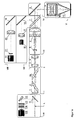
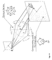
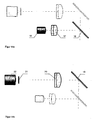
- FIG. 1a shows an exemplary overall view of all components of the scan head.
- the laser beam L generated by a laser source, not shown, and entering from the left into the optical components of the scan head first passes through a beam attenuation unit I. This serves to steplessly vary the power of the laser in an online operation during the execution of a laser drilling or laser cutting ,
- the jet then enters the tumble unit II.
- the main task of the tumble unit is to generate a beam offset parallel to the optical axis and thus to allow variable angles of incidence of the laser on the processed sample.
- the process performed in the tumble unit is also referred to as the tumbling process.
- the following beam expander unit or the beam expander telescope III essentially performs three important tasks.
- this unit increases the effective beam aperture to produce a required amount of focus.
- it increases the parallel beam offset generated by the wobble unit, thereby ensuring a required angle of incidence and controls in the form of a shift of the focal point in the Z direction, the position of the focused laser beam in the propagation direction.
- a beam splitter 7 then separates a visible radiation returning from the sample surface from the direction of propagation of the laser light and directing it into a series of testing and control units. This allows a visual observation of the drilling and cutting process and a plasma detection.
- the laser beam is deflected with a mirror arrangement in an X or Y direction, wherein the focus of the laser describes a required curve on the sample surface.
- the energy of the laser beam is focused on the sample to be processed by the working unit V with the aid of focusing optics 9 arranged therein.
- a beam profile unit VI for checking the parameters of the laser beam is inserted into the beam path in front of all other components and can optionally be connected via a shutter 11 be switched on.
- a plasma detector unit VII fed via the beam splitter 7 with essentially visible light and a viewing unit VII complete the exemplary structure shown in FIG. 1a.
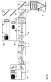
- Fig. 1b corresponds largely to the embodiment shown in Fig. 1a.
- a rotator unit Ia having a rotating ⁇ / 2 plate by means of which the polarization direction of the laser light can be adjusted.
- the beam attenuation unit I will be explained in more detail by way of example first.
- the physical background of this scanhead module is based on the reflection and polarization of light at dielectric optical interfaces, in particular on the Brewster angle phenomenon.
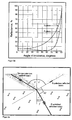
- FIGS. 2a and 2b illustrate the physical situation for this purpose.
- the reflection coefficient for incident light reflected at an interface between two dielectric media depends on the angle of incidence and the polarization direction of the light.
- the polarization state of the radiation is understood to be a superposition of two orthogonally oriented linear polarization directions. These fundamental directions are defined by their location with respect to the plane of incidence formed by the incident beam and the surface normal of the interface at the point of incidence of the incident beam.
- the polarization direction directed perpendicular to the plane of incidence is referred to as s-polarization, while the direction of polarization directed parallel to the plane of incidence bears the designation p-polarization.
- i and j denote the incidence or the refraction angle for the corresponding interface according to the known refraction law, as shown in FIG. 2b.
- i and j denote the incidence or the refraction angle for the corresponding interface according to the known refraction law, as shown in FIG. 2b.
- i and j denote the incidence or the refraction angle for the corresponding interface according to the known refraction law, as shown in FIG. 2b.
- FIG. 2a shows the reflexian coefficients r s and r p in percent as a function of the angle of incidence in °. It can be seen from Fig. 2a that r P disappears at an angle of incidence between 0 and 90 °. At this angle of incidence, no p-polarized light is reflected from the optical interface. This angle of incidence is called the Brewster angle. Because of the missing p-polarized component, the reflected beam is exclusively s-polarized.
- Fig. 2b A simple explanation for the Brewster angle can be taken from Fig. 2b.
- the beam reflected by the boundary surface and the beam refracted within the optically denser medium are perpendicular to one another, ie they enclose an angle of 90 °.
- parallel to the plane of incidence dipoles swing at the interface of the optically denser medium in the direction of the reflection angle and contribute according to their radiation characteristics no p-polarized light component to the reflected light intensity, while the s-polarized component provides a finite contribution.
- a plane-parallel plate mounted so that the incident beam is incident at the previously defined Brewster angle q B with the incident and refracted beams perpendicular to each other is referred to as the Brewster window.
- additional special coatings are applied to the interface of the Brewster window, which increase the reflectivity of the s-polarized component to a value of up to 99%. Under these conditions, the reflected light is completely s-polarized and the transmitted light has almost complete p-polarization.
- the beam attenuation unit I consists of two optical windows 2 and 2b, which are fixed in the Brewster angle, and a ⁇ / 2 plate or retarder 1.
- the second Brewster window compensates for the caused by the first Brewster window beam offset.
- the retarder 1 forms a particularly important element. It consists of a birefringent crystal or a birefringent film whose thickness is such that the phase difference between a normal and an extraordinary beam is exactly half a wavelength or ⁇ .
- an arrangement of a pair of immediately successive and identically oriented ⁇ / 4 plates may be provided instead of the retarder. This causes the same physical effect.
- An optional arrangement of a polarization crystal immediately behind the retarder forms a beam splitter for incident monochromatic linearly polarized light.
- the combination of the rotatable retarder 1 shown by way of example in FIG. 4 with the subsequent arrangement of the first Brewster window 2 and the second Brewster window 2a thus forms a continuous control possibility for the reflection and transmission of the laser light and enables continuous control or damping of the overall intensity of the beam.
- Both the retarder and the arrangement of the Brewster windows can be made rotatable.
- the retarder can be moved by a galvanometer.
- the galvanometer arrangement operating with a high setting accuracy can additionally be controlled by software in a control unit, wherein the rotation of the retarder can be adjusted on the basis of a large variability of pulse patterns and operating modes.
- controls in a step mode a linear continuous or in a non-linear continuous operation are possible, whereby the intensity of the laser is changed in a manner corresponding thereto.
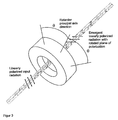
- FIG. 4 a shows its basic component, a ⁇ / 2 plate, with a sketch of the rotation of the polarization plane that can be achieved by rotation of the ⁇ / 2 plate.
- 4b illustrates the meaning of the position of the plane of polarization P with respect to a drilling or cutting edge K in a workpiece W.
- a ⁇ / 2 plate rotates the plane of polarization of linearly polarized light upon rotation of the retarder by the angle ⁇ in a new direction that deviates by the angle 2 ⁇ from the original direction of polarization. While in the mentioned beam attenuation unit I, this rotation of the polarization direction is used to regulate the intensity of the laser light, the ⁇ / 2 plate of the rotator unit is used to change the polarization direction of the emerging from the beam attenuation laser light defined.
- the polarization direction of the laser light and its linear polarization state are clearly defined by the fixed mechanical position of the Brewster windows 2 and 2a in the beam damping unit, so that the position of the ⁇ / 2 plate of the rotator Ia is always associated with a clear rotation of the plane of polarization, the external can be controlled for example by a servomotor or a Galvanometerwindung.
- FIG. 5 shows the beam propagation or the parallel beam offset of a beam incident obliquely into a plane-parallel plate
- FIG. 6 shows an exemplary embodiment of a tumbling unit according to the invention.
- the tumbling unit is composed of two plane-parallel optical glasses 3 and 4, which in turn are mounted on galvanometer arrangements. If the beam L falls through one of the two plates at a certain angle, the plate will call due to the refraction of light a beam offset parallel to its propagation direction.
- the beam offset depends on the refractive index of the disk, the thickness of the disk and the angle of incidence of the beam. Fig. 5 illustrates this with reference to a sketch.
- i is the angle of incidence of the beam
- j is the refractive angle resulting from the law of refraction at the first interface of the plate
- d is the thickness of the plate.
- the beam offset can thus be influenced and controlled.
- two such plates are provided in the embodiment shown here, which rotate about mutually orthogonal axes, or can be tilted.
- the two axes of rotation are each directed perpendicular to the propagation direction of the laser beam L.
- the beam can be offset in two mutually orthogonal directions parallel to the optical axis or to the initial propagation direction.
- different modes of rotation or tilting of the two plates can be provided. For example, tilting the two plates, which depends on a linear function, leads to a diagonal beam offset.
- the beam offset describes a circular path around the optical axis.
- the beam dislocations which can be generated practically with the described tumbling unit are in the range of a few millimeters. To obtain the desired angle of incidence in the focus of the sample, this displacement is not enough and must be strengthened.
- the beam expansion telescope III serves this purpose.
- FIGS. 7a and 7b represent essential optical principles of the beam expansion telescope III.
- refractive telescope optics are preferred for reasons of simple construction and performance.
- Typical refractive telescope optics are composed of two lenses or lens groups.
- the lens groups are arranged such that the focal length of the first lens group coincides with the focal length of the second lens group such that the two focal points of the lens groups coincide.
- the ratio M is the ratio between the focal lengths of the lens groups.
- f 1 and f 2 are the focal lengths of the lenses or lens groups and d the beam size of the beam before entering the telescope. M is thus simultaneously the magnification factor of the telescope.
- Fig. 7a shows an exemplary embodiment.
- the same magnification factor M can be achieved by a combination of two convex lenses or lens groups having positive focal lengths, i. a Kepler telescope, or by a combination of a convex and a concave lens, or a lens group with positive and a negative focal length, i. a Gallilei telescope, be realized.
- the embodiment of the Gallilei telescope i. the arrangement shown in Fig. 7a, is preferred here for reasons of shorter overall length. Furthermore, in such an embodiment, a focal point located between the lens groups and thus laser-induced heating and air breakdown are avoided.
- the beam expander telescope can be used as an amplifier unit for the beam offset generated by the wobble unit.
- the size of the focal spot tends to decrease under the influence of the diffraction effects by the finite aperture of the system, as long as the aperture is increased and as long as the optical aberrations of the system are sufficiently corrected.
- the gain of the beam offset of the laser beam does not necessarily lead to an enlargement of the focal spot itself, so that the beam is not widened, but only offset.
- the size of the focal spot can also be influenced by controlled displacements of one of the lenses or lens groups in the millimeter range along the propagation direction of the laser beam, whereby the numerical aperture of the beam is changed.
- the beam shape changes, the beam is no longer collimated in this case.
- This is accompanied by a change in the Z position of the focal spot.
- the influence of such a shift is different for each optical system.
- the displacement of the components of the telescope system can be carried out with a, depending on the optical layout, micrometer accuracy and the resulting effect can be monitored very closely.
- the jet thus offset parallel to the optical axis impinges on the scan block and is deflected by it in accordance with the contour to be generated on the sample.
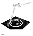
- Fig. 8 shows an exemplary mirror arrangement of a scan block.
- This unit is composed of two mirrors mounted on galvanometer units.
- a beam deflection is possible, which results in that the desired curve of the focal spot is drawn on the surface of the sample.
- this curve is a simple circle in most cases. This movement during drilling is called trephining and is done at very high speeds or rotations per minute.
- Each of the mirrors of the scan block is moved at an angular velocity of 90 ° / s for small aperture systems. This angular velocity corresponds to about 830 rpm.
- the optical beam deflection reaches, for example, a maximum of 50 °, and depending on the focusing optics used, the beam can be moved at a linear velocity of a few kilometers per second.
- the mirrors do not perform a complete circular motion during the scanning process. They are stopped at a certain tilt angle and continue their movement in the opposite direction.
- the positioning accuracy is in the range of a few micrometers, provided the mirrors are sufficient plan and hung with high accuracy in their centers of gravity and are thus balanced.
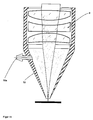
- FIG. 9 shows an exemplary spherical aberration for a more detailed explanation of the focusing optics 9 from the working unit V from FIG. 1a.
- the focusing optics are further shown enlarged in Fig. 11.
- the focusing optics serve to concentrate the laser power on the sample to be treated.
- the laser beam size may be in the range of one to ten millimeters in diameter.
- the resulting power density is not sufficient for the treatment of the sample and is increased by the focusing optics.
- the focusing optics for the correction of a number of aberrations in particular a spherical aberration or a coma aberration is designed.
- Spherical aberration occurs with an increasing beam aperture of the optical system.
- the rays removed from the optical axis are more strongly refracted at the lenses than the rays closer to the axis. Both beam types thus have a different focus.
- the caustic effect that occurs in this case leads to an undesired increase in the size of the focal spot and to a change in the intensity and energy distribution I across the beam cross section as a function of the position on the optical axis, as can be seen from the diagrams in the figure. This effect is undesirable and is suppressed by the focusing optics.
- the focusing optics must be designed to correct the coma aberration. This type of aberration occurs when the beam hits the lens at an angle to the optical axis or the object is out of the optical axis.
- different portions of the lens surface have different magnification factors. As can be seen from Fig. 10, each concentric zone of the lens forms an annular image called a coma circle. An object point outside the optical axis is then no longer a sharp corner or edge, but appears as surrounded by a comet-like tail.
- the units shown above each form separate modules of the scan head, each module being connected to a control device.
- This control device forms an interface that handles a data exchange between the device components of the scan head and a control software, such as InScript.
- FIG. 11 shows, in addition to the already mentioned focusing optics 9, a gas nozzle 10 with a gas feed 10a.
- This device serves to supply an auxiliary gas to the processed area.
- the gas may be the function of a protective gas to prevent oxidation.
- the gas nozzle is equipped with a pressure valve which is controlled by software of a control device.
- the gas pressure can be controlled during the material processing, wherein the result of the machining process can be influenced with a wide bandwidth.
- the entire module can be designed for a pressure resistance of up to 10 bar.
- Fig. 12 shows an exemplary beam profile unit VI.
- this test and control unit can be connected upstream of the entire device of the scan head.
- the exemplary embodiment consists of a mechanical shutter 11, additional optical elements for beam attenuation and deflection and a CCD camera 15 for observing the laser beam.
- This is equipped with an interference filter 14 and a series of absorption filters 13.
- With a closed shutter 11, the beam enters the beam profile unit.
- the shutter When the shutter is open, it enters the previously described units of the scan head.
- For deflecting the laser within the beam profile unit VI serves a wedge plate 12. The wedge shape prevents this ghost from the back of the plate on the CCD array of the camera.
- the interference filter 14 is permeable only to the operating wavelength of the laser and reduces the background radiation to a minimum.
- the blind closure BDS on the Rear side of the wedge plate 12 absorbs the radiation passing through the wedge plate and exiting at its rear side. If appropriate, it can be cooled, in particular at high power densities of the laser.
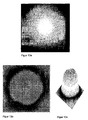
- the radiation registered on the CCD array of the camera 15 can subsequently be evaluated in detail with respect to a plurality of features, in particular intensity, beam strength, symmetry, using evaluation software.
- Figures 13a to 13c show examples thereof. 13a represents the raw image generated by the laser on the CCD array, while FIGS. 13b and 13c show different forms of representation of the energy distributions of the laser registered by the camera over the beam cross section in the form of a planar image or a simulated spatial representation.
- Fig. 14a shows an exemplary plasma sensor unit VII.
- the object of this module is to provide information about the plasma formation and structure.
- the plasma usually forms during material processing with laser radiation.
- information about the manner of a suitable and optimized material processing can be obtained.
- the main element of this module is the plasma sensor 18, which can be designed as a commercially available OEM device complete with the necessary optics and filter devices.
- a beam splitter 7, a semitransparent mirror 16, and a coupling optics 17 are shown in FIGS. 1 a and 1 b.
- the beam splitter 7 has on both sides a highly antireflective coating for the operating wavelength and thus enables a low-loss transmission of the laser light.
- the directed to the treated sample side of the beam splitter has a reflective coating for the visible wavelength spectrum.
- the laser light thus penetrates the beam splitter 7 essentially unhindered, while the visible light originating from the sample surface and from the plasma is reflected and thus directed in the direction of the plasma sensor unit and the viewing unit.
- the semitransparent mirror 16 directs this light to the viewing unit and redirects a portion to the plasma sensor 18.
- the coupling optics 17 focuses this light and aligns it with the plasma sensor 18.
- a photodiode which is arranged on the other side of the workpiece.
- the photodiode detects the laser radiation and thus signals a successful and complete completion of the machining process, i. a completely drilled hole or a completely separated part of the workpiece.
- the signal provided by the photodiode may be coupled to the control software of the scan head and responsive to an adjustment mechanics or adjustment optics of the scan head to jump to a next drilling or cutting position and begin a new machining operation thereon.
- no additional information about the interaction of the laser with the processed material can be obtained.
- Figure 14b shows an exemplary vision unit VIII which serves to precisely set up the scan head and view the machined area during processing.
- This module is designed for image rendering of the work surface on a CCD camera.
- the module according to FIG. 14b consists in particular of the following parts: a CCD camera 22, an imaging lens 20, a filter 21 and a beam splitter 19.
- the lens 20 forms a projection unit in conjunction with the focusing optics 9 of the scan head.
- the lenses and their additional coatings are typically optimized not for optical imaging in the visible wavelength range, but for guiding and focusing a higher power laser.
- Fig. 15 is used.
- FIG. 15 shows a simplified schematic lens arrangement of two lens units L1 and L2.
- M t f 1 ⁇ f 2 s 1 - f 1 ⁇ d - f 2 - s 1 ⁇ f 1 / s 1 - f 1 ,
- the focal length of the second element is assumed to be 200mm as a compromise between the length and magnification of the system.
- the tip of the gas nozzle described above can be assumed, which has a diameter of about 1mm.
- the distance between the first lens and the object is slightly larger than the focal length and can be assumed to be about s 1 ⁇ 121mm.
Claims (28)
- Tête de balayage en tant que partie d'un dispositif de perçage et de découpe à laser, comprenant :une série, agencée dans le trajet lumineux du laser, formée des composants suivants :une unité d'amortissement de rayonnement (I) assurant la régulation d'intensité ; un télescope (III) qui agrandit la section du rayonnement laser, un bloc de balayage (IV) qui mène le foyer du rayonnement laser, etune unité de travail (V) qui focalise le rayon laser sur un échantillon, ainsi que des unités de vérification et de contrôle additionnelles susceptible d'être couplées en option dans le trajet lumineux, caractérisée en ce qu'il est prévu, en liaison avec l'unité d'amortissement de rayonnement, une unité (II) oscillante qui assure la régulation d'un décalage parallèle du rayonnement.
- Tête de balayage selon la revendication 1, caractérisée en ce que l'unité d'amortissement de rayonnement (I) comprend une succession, agencée dans le trajet lumineux, formé d'une plaquette à □/2 ou d'un retardateur (1), d'une première fenêtre de Brewster (2) et d'une seconde fenêtre de Brewster (2a), dans laquelle le retardateur et/ou l'une au moins des deux fenêtres de Brewster est réalisé rotatif autour de l'axe optique.
- Tête de balayage selon la revendication 2, caractérisé en ce qu'il est prévu une unité galvanométrique qui fait tourner le retardateur (1) autour de l'axe optique.
- Tête de balayage selon l'une des revendications précédentes, caractérisée en ce que, dans un mode de réalisation, une unité rotative (Ia) qui fait tourner la direction de polarisation du rayonnement laser est introduite entre l'unité d'amortissement de rayonnement (I) et l'unité oscillante (II).
- Tête de balayage selon la revendication 4, caractérisée en ce que l'unité rotative (Ia) comprend une plaquette à □/2 (2b) avec angle de réglage réglable depuis l'extérieur.
- Tête de balayage selon l'une des revendications 4 au 5, caractérisée en ce que l'angle de réglage de la plaquette à □/2 correspond à une direction de polarisation linéaire du rayonnement laser dirigé sensiblement perpendiculairement localement par rapport à un flanc d'une jointure de coupe.
- Tête de balayage selon l'une des revendications 4 à 6, caractérisée par une unité de commande qui modifie l'angle de réglage de la plaquette à □/2 en fonction d'un contour prédéterminé de la jointure de coupe, en association avec une unité de réglage mécanique.
- Tête de balayage selon l'une des revendications précédentes, caractérisée en ce que l'unité oscillante (II) est réalisée par un agencement, introduit dans le trajet lumineux, constitué de deux fenêtres (3, 4) à plans parallèles, dans lesquelles l'axe de rotation de la première fenêtre (3) à plan parallèle, l'axe de rotation de la seconde fenêtre (4) à plan parallèle, et le sens de propagation du rayonnement laser sont orthogonaux les uns aux autres.
- Tête de balayage selon la revendication 8, caractérisée en ce que les fenêtres (3, 4) à plans parallèles sont des unités galvanométriques tournant autour de leurs axes de rotation respectifs.
- Tête de balayage selon l'une des revendications précédentes, caractérisée en ce que le télescope (III) est réalisé sous forme d'un agencement à lentille élargissant le rayonnement par réfraction.
- Tête de balayage selon la revendication 10, caractérisée en ce que le télescope (III) est réalisé sous forme de télescope de Galilée avec au moins une lentille concave (5) est au moins un agencement à lentille de collimation convexe (6).
- Tête de balayage selon la revendication 11, caractérisée en ce que l'agencement optique du télescope (III) comprend un agencement à lentille additionnel corrigeant les aberrations.
- Tête de balayage selon l'une des revendications 10 à 12, caractérisée en ce que la lentille concave (5) et/ou l'agencement de lentille de collimation (6) est monté en translation le long de l'axe optique.
- Tête de balayage selon l'une des revendications précédentes, caractérisée en ce que le bloc de balayage (IV) est réalisé sous forme d'un agencement de deux miroirs individuels (8, 8a) en rotation.
- Tête de balayage selon la revendication 14, caractérisée en ce que les miroirs individuels (8, 8a) sont agencés sur des moyens de rotation pour des vitesses angulaires dans la plage de 90 radians/seconde et plus.
- Tête de balayage selon l'une des revendications précédentes, caractérisée en ce que l'unité de travail (V) est réalisée sous forme d'une combinaison d'une optique de focalisation (9) et d'une buse à gaz (10).
- Tête de balayage selon la revendication 16, caractérisée en ce que l'optique de focalisation (9) comprend des éléments de correction optique au moins pour compenser une aberration sphérique et/ou une aberration de Coma.
- Tête de balayage selon l'une des revendications 16 ou 17, caractérisée en ce que la buse à gaz (10) comprend une amenée de gaz avec une valve de pression commandée par programme.
- Tête de balayage selon la revendication 1, caractérisée en ce qu'il est prévu à titre d'unité additionnelle de vérification et de contrôle une unité de profilage de rayonnement (VI) avec des composantes pour un couplage sélectif de l'unité de profilage de rayonnement dans le trajet lumineux, divers dispositif de filtration, et un dispositif à caméra détectant le profilage de rayonnement.
- Tête de balayage selon la revendication 19, caractérisée en ce que les composantes pour le couplage sélectif sont réalisées par un obturateur mécanique (11), en particulier sous la forme d'un miroir ou d'un prisme rabattable.
- Tête de balayage selon l'une des revendications 19 ou 20, caractérisée en ce qu'un premier dispositif de filtration dans l'unité de profilage de rayonnement (VI) est réalisée par une plaque en coin (12), évitant une image double, en association avec un obturateur borgne (BDS).
- Tête de balayage selon l'une des revendications 19 à 21, caractérisée en ce qu'un autre dispositif de filtration dans l'unité de profilage de rayonnement (VI) est réalisé par un agencement de filtrage par absorption réduisant l'intensité, en particulier une cascade de filtres par absorption (13).
- Tête de balayage selon l'une des revendications 19 à 22, caractérisée en ce qu'il est prévu un autre dispositif de filtration sous la forme d'un filtre à interférence (14) transparent pour une longueur d'onde de travail donnée.
- Tête de balayage selon l'une des revendications 19 à 23, caractérisée en ce que le dispositif à caméra est réalisé par une caméra à CCD (15) en association avec un logiciel de traitement d'images.
- Tête de balayage selon la revendication 19, caractérisée en ce qu'il est prévu à titre d'unité additionnelle de vérification et de contrôle une unité de détecteur à plasma (VII) qui enregistre une formation et une structure de plasma.
- Tête de balayage selon la revendication 25, caractérisée en ce que l'unité de détecteur à plasma (VII) comprend un miroir semi-transparent (16), une optique de couplage (17) et un détecteur de plasma (18).
- Tête de balayage selon la revendication 19, caractérisée en ce qu'il est prévu à titre d'unité additionnelle de vérification et de contrôle une unité de visualisation (VIII) pour l'observation visuelle du foyer.
- Tête de balayage selon la revendication 27, caractérisée en ce que l'unité de visualisation (VIII) comprend une optique de projection coopérant avec l'optique de focalisation (9), un dispositif de filtrage (21) et un dispositif à caméra, en particulier un dispositif à caméra CCD (22).
Applications Claiming Priority (3)
| Application Number | Priority Date | Filing Date | Title |
|---|---|---|---|
| DE102004041389 | 2004-08-26 | ||
| DE102004053298A DE102004053298B4 (de) | 2004-08-26 | 2004-11-04 | Scankopf als Teil einer Laser Bohr- und Schneideinrichtung |
| PCT/EP2005/009196 WO2006021442A1 (fr) | 2004-08-26 | 2005-08-25 | Tete de balayage faisant partie d'un dispositif de forage et de decoupe laser |
Publications (2)
| Publication Number | Publication Date |
|---|---|
| EP1656234A1 EP1656234A1 (fr) | 2006-05-17 |
| EP1656234B1 true EP1656234B1 (fr) | 2007-01-17 |
Family
ID=35295347
Family Applications (1)
| Application Number | Title | Priority Date | Filing Date |
|---|---|---|---|
| EP05783447A Active EP1656234B1 (fr) | 2004-08-26 | 2005-08-25 | Tete de balayage faisant partie d'un dispositif de forage et de decoupe laser |
Country Status (3)
| Country | Link |
|---|---|
| EP (1) | EP1656234B1 (fr) |
| DE (2) | DE102004053298B4 (fr) |
| WO (1) | WO2006021442A1 (fr) |
Cited By (1)
| Publication number | Priority date | Publication date | Assignee | Title |
|---|---|---|---|---|
| DE102014108259A1 (de) | 2014-06-12 | 2015-12-17 | Scanlab Ag | Vorrichtung zur Lasermaterialbearbeitung |
Families Citing this family (16)
| Publication number | Priority date | Publication date | Assignee | Title |
|---|---|---|---|---|
| JP4386137B2 (ja) * | 2008-02-29 | 2009-12-16 | トヨタ自動車株式会社 | レーザ加工装置及びレーザ加工方法 |
| CN101966623A (zh) * | 2010-11-05 | 2011-02-09 | 山东理工大学 | 用激光切割圆形、弧形的装置 |
| EE05696B1 (et) * | 2011-01-20 | 2013-12-16 | Visiometric Oü | Liinilaseril p?hinevate skannerite töö parandamise tehniline lahendus ja meetod selle teostamiseks |
| KR101346296B1 (ko) * | 2012-01-20 | 2014-01-02 | 참엔지니어링(주) | 레이저 가공 장치 및 방법 |
| CN102653030B (zh) * | 2012-04-20 | 2015-05-20 | 华中科技大学 | 一种多功能激光加工头 |
| DE102012212278B4 (de) * | 2012-07-13 | 2016-12-15 | Arges Gmbh | Anordnung zum Erzeugen von Bohrungen oder Schweißnähten |
| CN103317233B (zh) * | 2013-06-07 | 2015-02-18 | 张立国 | 一种用于激光加工的光束运动轨迹控制装置 |
| DE102013222834A1 (de) * | 2013-11-11 | 2015-05-13 | Robert Bosch Gmbh | Vorrichtung und Verfahren zur Führung eines Laserstrahls |
| EP2962802B1 (fr) * | 2014-07-04 | 2017-03-01 | Ideko, S. Coop | Tête d'inspection et d'usinage laser |
| CN104849859B (zh) * | 2015-05-19 | 2017-10-31 | 中国人民解放军63655部队 | 一种激光传输光束抖动效应的数值模拟方法 |
| DE102015109984A1 (de) | 2015-06-22 | 2016-12-22 | Scanlab Ag | Scannerkopf mit integriertem Strahllagesensor sowie Justageanordnung zur Offline-Justage |
| CN107138862B (zh) * | 2017-06-20 | 2023-10-20 | 深圳市韵腾激光科技有限公司 | 一种激光旋转切割装置及方法 |
| GB201712639D0 (en) * | 2017-08-07 | 2017-09-20 | Univ Oxford Innovation Ltd | Method for laser machining inside materials |
| US10705327B2 (en) | 2018-01-02 | 2020-07-07 | Industrial Technology Research Institute | Light emitting method and light emitting device |
| DE102021122662A1 (de) | 2021-09-01 | 2023-03-02 | Scanlab Gmbh | Optikeinheit für eine Laserbearbeitungsvorrichtung |
| JP2023161992A (ja) | 2022-04-26 | 2023-11-08 | キヤノン株式会社 | 加工装置及び物品の製造方法 |
Family Cites Families (3)
| Publication number | Priority date | Publication date | Assignee | Title |
|---|---|---|---|---|
| US6300590B1 (en) * | 1998-12-16 | 2001-10-09 | General Scanning, Inc. | Laser processing |
| DE10054853A1 (de) * | 2000-11-06 | 2002-08-01 | Bosch Gmbh Robert | Verfahren zum Einbringen eines Mikrolochs in ein vorzugsweise metallisches Werkstück und Vorrichtung hierzu |
| US20040017430A1 (en) * | 2002-07-23 | 2004-01-29 | Yosuke Mizuyama | Laser processing method and laser processing apparatus |
-
2004
- 2004-11-04 DE DE102004053298A patent/DE102004053298B4/de not_active Expired - Fee Related
-
2005
- 2005-08-25 DE DE502005000324T patent/DE502005000324D1/de active Active
- 2005-08-25 WO PCT/EP2005/009196 patent/WO2006021442A1/fr active IP Right Grant
- 2005-08-25 EP EP05783447A patent/EP1656234B1/fr active Active
Cited By (5)
| Publication number | Priority date | Publication date | Assignee | Title |
|---|---|---|---|---|
| DE102014108259A1 (de) | 2014-06-12 | 2015-12-17 | Scanlab Ag | Vorrichtung zur Lasermaterialbearbeitung |
| WO2015189241A1 (fr) | 2014-06-12 | 2015-12-17 | Scanlab Ag | Dispositif d'usinage de matériaux par laser à unité à déplacement parallèle |
| KR20170015369A (ko) | 2014-06-12 | 2017-02-08 | 슈칸랍 게엠베하 옵티쉐 테히놀로기엔 | 평행-오프셋 유닛을 포함하는 레이저 재료 가공 장치 |
| US10272521B2 (en) | 2014-06-12 | 2019-04-30 | Scanlab Gmbh | Laser machining apparatus comprising a parallel displacement unit |
| EP3932609A1 (fr) | 2014-06-12 | 2022-01-05 | Scanlab GmbH | Dispositif d'usinage laser des matériaux avec deux unitées de décalage parallèle du faisceau laser |
Also Published As
| Publication number | Publication date |
|---|---|
| DE102004053298A1 (de) | 2006-03-30 |
| EP1656234A1 (fr) | 2006-05-17 |
| DE102004053298B4 (de) | 2008-10-09 |
| WO2006021442A1 (fr) | 2006-03-02 |
| DE502005000324D1 (de) | 2007-03-08 |
Similar Documents
| Publication | Publication Date | Title |
|---|---|---|
| EP1656234B1 (fr) | Tete de balayage faisant partie d'un dispositif de forage et de decoupe laser | |
| EP3140609B1 (fr) | Dispositif de mesure de la profondeur d'un cordon de soudure en temps réel | |
| EP0168351B1 (fr) | Générateur laser de motifs et procédé pour son emploi | |
| DE69933224T2 (de) | Steuerung der laserpolarisation | |
| DE102013015656B4 (de) | Verfahren zum Messen der Eindringtiefe eines Laserstrahls in ein Werkstück, Verfahren zum Bearbeiten eines Werkstücks sowie Laserbearbeitungsvorrichtung | |
| EP2150372B1 (fr) | Procédé d'enlèvement de matière et dispositif pour réaliser ce procédé | |
| EP1465747B1 (fr) | Dispositif d'usinage par laser | |
| DE102011054941B3 (de) | Vorrichtung und Verfahren zur Korrektur der thermischen Verschiebung der Fokuslage von über Optiken geführten Laserstrahlen | |
| EP3583390B1 (fr) | Procédé et dispositif de détection d'une position focale d'un faisceau laser | |
| DE102009007769A1 (de) | Laserbearbeitungskopf mit integrierter Sensoreinrichtung zur Fokuslagenüberwachung | |
| DE4009089A1 (de) | Mehrfasernhalter fuer ausgangskuppler und verfahren zu dessen anwendung | |
| WO2013113479A1 (fr) | Procédé permettant de réguler un processus de coupe au laser et machine de coupe au laser | |
| DE19933825B4 (de) | Laserbearbeitungsvorrichtung | |
| EP3917716B1 (fr) | Dispositif et procédé pour former un faisceau laser | |
| WO2015189241A1 (fr) | Dispositif d'usinage de matériaux par laser à unité à déplacement parallèle | |
| EP3942656A1 (fr) | Procédé d'ajustement d'un faisceau laser, dispositif de fourniture d'un faisceau laser ajusté et agencement optique | |
| DE102015115270A1 (de) | Verfahren zur Herstellung einer Schweißverbindung in einem Fügespalt und Prozessbeobachtungsvorrichtung | |
| EP0791818A2 (fr) | Méthode et appareil pour l'examen photothermique d'une pièce à usiner | |
| DE2505774C3 (de) | Justiervorrichtung für eine Laseranordnung aus einem Leistungslaser und einem Justierlaser | |
| DE102021101658B4 (de) | Laserbearbeitungskopf mit chromatischer Kompensationsvorrichtung | |
| DE102006055595A1 (de) | Vorrichtung und Verfahren zur Regelung der Leistung eines Laserstrahls | |
| EP1742307B1 (fr) | Dispositif pour le contrôle de la polarisation d'un faisceau laser | |
| DE102007062825A1 (de) | Gitterspiegel zur Online-Überwachung eines Laserstrahls und Überwachungsvorrichtung damit | |
| EP1415756B1 (fr) | Méthode et dispositif de contrôle de l'énergie d'un faisceau laser à l'aide d'une paire d'élément Brewster tournant dans des directions opposées | |
| EP3928913A1 (fr) | Tête d'usinage et procédé d'usinage laser |
Legal Events
| Date | Code | Title | Description |
|---|---|---|---|
| PUAI | Public reference made under article 153(3) epc to a published international application that has entered the european phase |
Free format text: ORIGINAL CODE: 0009012 |
|
| 17P | Request for examination filed |
Effective date: 20060220 |
|
| AK | Designated contracting states |
Kind code of ref document: A1 Designated state(s): AT BE BG CH CY CZ DE DK EE ES FI FR GB GR HU IE IS IT LI LT LU LV MC NL PL PT RO SE SI SK TR |
|
| AX | Request for extension of the european patent |
Extension state: AL BA HR MK YU |
|
| GRAP | Despatch of communication of intention to grant a patent |
Free format text: ORIGINAL CODE: EPIDOSNIGR1 |
|
| GRAS | Grant fee paid |
Free format text: ORIGINAL CODE: EPIDOSNIGR3 |
|
| GRAA | (expected) grant |
Free format text: ORIGINAL CODE: 0009210 |
|
| AK | Designated contracting states |
Kind code of ref document: B1 Designated state(s): AT BE BG CH CY CZ DE DK EE ES FI FR GB GR HU IE IS IT LI LT LU LV MC NL PL PT RO SE SI SK TR |
|
| DAX | Request for extension of the european patent (deleted) | ||
| PG25 | Lapsed in a contracting state [announced via postgrant information from national office to epo] |
Ref country code: FI Free format text: LAPSE BECAUSE OF FAILURE TO SUBMIT A TRANSLATION OF THE DESCRIPTION OR TO PAY THE FEE WITHIN THE PRESCRIBED TIME-LIMIT Effective date: 20070117 Ref country code: DK Free format text: LAPSE BECAUSE OF FAILURE TO SUBMIT A TRANSLATION OF THE DESCRIPTION OR TO PAY THE FEE WITHIN THE PRESCRIBED TIME-LIMIT Effective date: 20070117 Ref country code: SI Free format text: LAPSE BECAUSE OF FAILURE TO SUBMIT A TRANSLATION OF THE DESCRIPTION OR TO PAY THE FEE WITHIN THE PRESCRIBED TIME-LIMIT Effective date: 20070117 Ref country code: IE Free format text: LAPSE BECAUSE OF FAILURE TO SUBMIT A TRANSLATION OF THE DESCRIPTION OR TO PAY THE FEE WITHIN THE PRESCRIBED TIME-LIMIT Effective date: 20070117 Ref country code: PL Free format text: LAPSE BECAUSE OF FAILURE TO SUBMIT A TRANSLATION OF THE DESCRIPTION OR TO PAY THE FEE WITHIN THE PRESCRIBED TIME-LIMIT Effective date: 20070117 Ref country code: NL Free format text: LAPSE BECAUSE OF FAILURE TO SUBMIT A TRANSLATION OF THE DESCRIPTION OR TO PAY THE FEE WITHIN THE PRESCRIBED TIME-LIMIT Effective date: 20070117 |
|
| REG | Reference to a national code |
Ref country code: GB Ref legal event code: FG4D Free format text: NOT ENGLISH |
|
| REG | Reference to a national code |
Ref country code: CH Ref legal event code: EP |
|
| REG | Reference to a national code |
Ref country code: IE Ref legal event code: FG4D Free format text: LANGUAGE OF EP DOCUMENT: GERMAN |
|
| REF | Corresponds to: |
Ref document number: 502005000324 Country of ref document: DE Date of ref document: 20070308 Kind code of ref document: P |
|
| PG25 | Lapsed in a contracting state [announced via postgrant information from national office to epo] |
Ref country code: SE Free format text: LAPSE BECAUSE OF FAILURE TO SUBMIT A TRANSLATION OF THE DESCRIPTION OR TO PAY THE FEE WITHIN THE PRESCRIBED TIME-LIMIT Effective date: 20070417 Ref country code: BG Free format text: LAPSE BECAUSE OF FAILURE TO SUBMIT A TRANSLATION OF THE DESCRIPTION OR TO PAY THE FEE WITHIN THE PRESCRIBED TIME-LIMIT Effective date: 20070417 |
|
| PG25 | Lapsed in a contracting state [announced via postgrant information from national office to epo] |
Ref country code: ES Free format text: LAPSE BECAUSE OF FAILURE TO SUBMIT A TRANSLATION OF THE DESCRIPTION OR TO PAY THE FEE WITHIN THE PRESCRIBED TIME-LIMIT Effective date: 20070428 |
|
| PG25 | Lapsed in a contracting state [announced via postgrant information from national office to epo] |
Ref country code: IS Free format text: LAPSE BECAUSE OF FAILURE TO SUBMIT A TRANSLATION OF THE DESCRIPTION OR TO PAY THE FEE WITHIN THE PRESCRIBED TIME-LIMIT Effective date: 20070517 |
|
| RIN2 | Information on inventor provided after grant (corrected) |
Inventor name: BADYUKOV, DMITRY Inventor name: GUGGENMOS, MARKUS Inventor name: HARTMANN, MARTIN |
|
| PG25 | Lapsed in a contracting state [announced via postgrant information from national office to epo] |
Ref country code: PT Free format text: LAPSE BECAUSE OF FAILURE TO SUBMIT A TRANSLATION OF THE DESCRIPTION OR TO PAY THE FEE WITHIN THE PRESCRIBED TIME-LIMIT Effective date: 20070618 |
|
| NLV1 | Nl: lapsed or annulled due to failure to fulfill the requirements of art. 29p and 29m of the patents act | ||
| GBV | Gb: ep patent (uk) treated as always having been void in accordance with gb section 77(7)/1977 [no translation filed] |
Effective date: 20070117 |
|
| REG | Reference to a national code |
Ref country code: IE Ref legal event code: FD4D |
|
| PLBE | No opposition filed within time limit |
Free format text: ORIGINAL CODE: 0009261 |
|
| STAA | Information on the status of an ep patent application or granted ep patent |
Free format text: STATUS: NO OPPOSITION FILED WITHIN TIME LIMIT |
|
| PG25 | Lapsed in a contracting state [announced via postgrant information from national office to epo] |
Ref country code: SK Free format text: LAPSE BECAUSE OF FAILURE TO SUBMIT A TRANSLATION OF THE DESCRIPTION OR TO PAY THE FEE WITHIN THE PRESCRIBED TIME-LIMIT Effective date: 20070117 Ref country code: GB Free format text: LAPSE BECAUSE OF FAILURE TO SUBMIT A TRANSLATION OF THE DESCRIPTION OR TO PAY THE FEE WITHIN THE PRESCRIBED TIME-LIMIT Effective date: 20070117 |
|
| 26N | No opposition filed |
Effective date: 20071018 |
|
| PG25 | Lapsed in a contracting state [announced via postgrant information from national office to epo] |
Ref country code: RO Free format text: LAPSE BECAUSE OF FAILURE TO SUBMIT A TRANSLATION OF THE DESCRIPTION OR TO PAY THE FEE WITHIN THE PRESCRIBED TIME-LIMIT Effective date: 20070117 Ref country code: CZ Free format text: LAPSE BECAUSE OF FAILURE TO SUBMIT A TRANSLATION OF THE DESCRIPTION OR TO PAY THE FEE WITHIN THE PRESCRIBED TIME-LIMIT Effective date: 20070117 |
|
| PG25 | Lapsed in a contracting state [announced via postgrant information from national office to epo] |
Ref country code: LV Free format text: LAPSE BECAUSE OF FAILURE TO SUBMIT A TRANSLATION OF THE DESCRIPTION OR TO PAY THE FEE WITHIN THE PRESCRIBED TIME-LIMIT Effective date: 20070117 |
|
| BERE | Be: lapsed |
Owner name: ARGES G.- FUR INDUSTRIEPLANUNG UND LASERTECHNIK M Effective date: 20070831 |
|
| PG25 | Lapsed in a contracting state [announced via postgrant information from national office to epo] |
Ref country code: LT Free format text: LAPSE BECAUSE OF FAILURE TO SUBMIT A TRANSLATION OF THE DESCRIPTION OR TO PAY THE FEE WITHIN THE PRESCRIBED TIME-LIMIT Effective date: 20070117 |
|
| PG25 | Lapsed in a contracting state [announced via postgrant information from national office to epo] |
Ref country code: IT Free format text: LAPSE BECAUSE OF FAILURE TO SUBMIT A TRANSLATION OF THE DESCRIPTION OR TO PAY THE FEE WITHIN THE PRESCRIBED TIME-LIMIT Effective date: 20070117 Ref country code: MC Free format text: LAPSE BECAUSE OF NON-PAYMENT OF DUE FEES Effective date: 20070831 Ref country code: FR Free format text: LAPSE BECAUSE OF FAILURE TO SUBMIT A TRANSLATION OF THE DESCRIPTION OR TO PAY THE FEE WITHIN THE PRESCRIBED TIME-LIMIT Effective date: 20070907 Ref country code: GR Free format text: LAPSE BECAUSE OF FAILURE TO SUBMIT A TRANSLATION OF THE DESCRIPTION OR TO PAY THE FEE WITHIN THE PRESCRIBED TIME-LIMIT Effective date: 20070418 |
|
| PG25 | Lapsed in a contracting state [announced via postgrant information from national office to epo] |
Ref country code: BE Free format text: LAPSE BECAUSE OF NON-PAYMENT OF DUE FEES Effective date: 20070831 |
|
| PG25 | Lapsed in a contracting state [announced via postgrant information from national office to epo] |
Ref country code: FR Free format text: LAPSE BECAUSE OF FAILURE TO SUBMIT A TRANSLATION OF THE DESCRIPTION OR TO PAY THE FEE WITHIN THE PRESCRIBED TIME-LIMIT Effective date: 20070117 Ref country code: AT Free format text: LAPSE BECAUSE OF NON-PAYMENT OF DUE FEES Effective date: 20070825 |
|
| PG25 | Lapsed in a contracting state [announced via postgrant information from national office to epo] |
Ref country code: EE Free format text: LAPSE BECAUSE OF FAILURE TO SUBMIT A TRANSLATION OF THE DESCRIPTION OR TO PAY THE FEE WITHIN THE PRESCRIBED TIME-LIMIT Effective date: 20070117 |
|
| PG25 | Lapsed in a contracting state [announced via postgrant information from national office to epo] |
Ref country code: CY Free format text: LAPSE BECAUSE OF FAILURE TO SUBMIT A TRANSLATION OF THE DESCRIPTION OR TO PAY THE FEE WITHIN THE PRESCRIBED TIME-LIMIT Effective date: 20070117 |
|
| PG25 | Lapsed in a contracting state [announced via postgrant information from national office to epo] |
Ref country code: LU Free format text: LAPSE BECAUSE OF NON-PAYMENT OF DUE FEES Effective date: 20070825 |
|
| PG25 | Lapsed in a contracting state [announced via postgrant information from national office to epo] |
Ref country code: TR Free format text: LAPSE BECAUSE OF FAILURE TO SUBMIT A TRANSLATION OF THE DESCRIPTION OR TO PAY THE FEE WITHIN THE PRESCRIBED TIME-LIMIT Effective date: 20070117 Ref country code: HU Free format text: LAPSE BECAUSE OF FAILURE TO SUBMIT A TRANSLATION OF THE DESCRIPTION OR TO PAY THE FEE WITHIN THE PRESCRIBED TIME-LIMIT Effective date: 20070718 |
|
| REG | Reference to a national code |
Ref country code: CH Ref legal event code: PL |
|
| PG25 | Lapsed in a contracting state [announced via postgrant information from national office to epo] |
Ref country code: LI Free format text: LAPSE BECAUSE OF NON-PAYMENT OF DUE FEES Effective date: 20090831 Ref country code: CH Free format text: LAPSE BECAUSE OF NON-PAYMENT OF DUE FEES Effective date: 20090831 |
|
| REG | Reference to a national code |
Ref country code: DE Ref legal event code: R082 Ref document number: 502005000324 Country of ref document: DE Representative=s name: MEISSNER BOLTE PATENTANWAELTE RECHTSANWAELTE P, DE Ref country code: DE Ref legal event code: R081 Ref document number: 502005000324 Country of ref document: DE Owner name: NOVANTA EUROPE GMBH, DE Free format text: FORMER OWNER: ARGES GESELLSCHAFT FUER INDUSTRIEPLANUNG UND LASERTECHNIK M.B.H., 92507 NABBURG, DE |
|
| P01 | Opt-out of the competence of the unified patent court (upc) registered |
Effective date: 20230706 |
|
| PGFP | Annual fee paid to national office [announced via postgrant information from national office to epo] |
Ref country code: DE Payment date: 20230831 Year of fee payment: 19 |