EP1655183B1 - Knee-protecting airbag device - Google Patents
Knee-protecting airbag device Download PDFInfo
- Publication number
- EP1655183B1 EP1655183B1 EP05024007A EP05024007A EP1655183B1 EP 1655183 B1 EP1655183 B1 EP 1655183B1 EP 05024007 A EP05024007 A EP 05024007A EP 05024007 A EP05024007 A EP 05024007A EP 1655183 B1 EP1655183 B1 EP 1655183B1
- Authority
- EP
- European Patent Office
- Prior art keywords
- airbag
- protecting
- tether
- knee
- area
- Prior art date
- Legal status (The legal status is an assumption and is not a legal conclusion. Google has not performed a legal analysis and makes no representation as to the accuracy of the status listed.)
- Ceased
Links
Images


Classifications
-
- B—PERFORMING OPERATIONS; TRANSPORTING
- B60—VEHICLES IN GENERAL
- B60R—VEHICLES, VEHICLE FITTINGS, OR VEHICLE PARTS, NOT OTHERWISE PROVIDED FOR
- B60R21/00—Arrangements or fittings on vehicles for protecting or preventing injuries to occupants or pedestrians in case of accidents or other traffic risks
- B60R21/02—Occupant safety arrangements or fittings, e.g. crash pads
- B60R21/16—Inflatable occupant restraints or confinements designed to inflate upon impact or impending impact, e.g. air bags
- B60R21/23—Inflatable members
- B60R21/231—Inflatable members characterised by their shape, construction or spatial configuration
- B60R21/233—Inflatable members characterised by their shape, construction or spatial configuration comprising a plurality of individual compartments; comprising two or more bag-like members, one within the other
-
- B—PERFORMING OPERATIONS; TRANSPORTING
- B60—VEHICLES IN GENERAL
- B60R—VEHICLES, VEHICLE FITTINGS, OR VEHICLE PARTS, NOT OTHERWISE PROVIDED FOR
- B60R21/00—Arrangements or fittings on vehicles for protecting or preventing injuries to occupants or pedestrians in case of accidents or other traffic risks
- B60R21/02—Occupant safety arrangements or fittings, e.g. crash pads
- B60R21/16—Inflatable occupant restraints or confinements designed to inflate upon impact or impending impact, e.g. air bags
- B60R21/20—Arrangements for storing inflatable members in their non-use or deflated condition; Arrangement or mounting of air bag modules or components
- B60R21/205—Arrangements for storing inflatable members in their non-use or deflated condition; Arrangement or mounting of air bag modules or components in dashboards
- B60R21/206—Arrangements for storing inflatable members in their non-use or deflated condition; Arrangement or mounting of air bag modules or components in dashboards in the lower part of dashboards, e.g. for protecting the knees
-
- B—PERFORMING OPERATIONS; TRANSPORTING
- B60—VEHICLES IN GENERAL
- B60R—VEHICLES, VEHICLE FITTINGS, OR VEHICLE PARTS, NOT OTHERWISE PROVIDED FOR
- B60R21/00—Arrangements or fittings on vehicles for protecting or preventing injuries to occupants or pedestrians in case of accidents or other traffic risks
- B60R2021/003—Arrangements or fittings on vehicles for protecting or preventing injuries to occupants or pedestrians in case of accidents or other traffic risks characterised by occupant or pedestian
- B60R2021/0039—Body parts of the occupant or pedestrian affected by the accident
- B60R2021/0053—Legs
-
- B—PERFORMING OPERATIONS; TRANSPORTING
- B60—VEHICLES IN GENERAL
- B60R—VEHICLES, VEHICLE FITTINGS, OR VEHICLE PARTS, NOT OTHERWISE PROVIDED FOR
- B60R21/00—Arrangements or fittings on vehicles for protecting or preventing injuries to occupants or pedestrians in case of accidents or other traffic risks
- B60R21/02—Occupant safety arrangements or fittings, e.g. crash pads
- B60R21/16—Inflatable occupant restraints or confinements designed to inflate upon impact or impending impact, e.g. air bags
- B60R21/23—Inflatable members
- B60R21/231—Inflatable members characterised by their shape, construction or spatial configuration
- B60R2021/23169—Inflatable members characterised by their shape, construction or spatial configuration specially adapted for knee protection
-
- B—PERFORMING OPERATIONS; TRANSPORTING
- B60—VEHICLES IN GENERAL
- B60R—VEHICLES, VEHICLE FITTINGS, OR VEHICLE PARTS, NOT OTHERWISE PROVIDED FOR
- B60R21/00—Arrangements or fittings on vehicles for protecting or preventing injuries to occupants or pedestrians in case of accidents or other traffic risks
- B60R21/02—Occupant safety arrangements or fittings, e.g. crash pads
- B60R21/16—Inflatable occupant restraints or confinements designed to inflate upon impact or impending impact, e.g. air bags
- B60R21/23—Inflatable members
- B60R21/231—Inflatable members characterised by their shape, construction or spatial configuration
- B60R21/233—Inflatable members characterised by their shape, construction or spatial configuration comprising a plurality of individual compartments; comprising two or more bag-like members, one within the other
- B60R2021/23324—Inner walls crating separate compartments, e.g. communicating with vents
-
- B—PERFORMING OPERATIONS; TRANSPORTING
- B60—VEHICLES IN GENERAL
- B60R—VEHICLES, VEHICLE FITTINGS, OR VEHICLE PARTS, NOT OTHERWISE PROVIDED FOR
- B60R21/00—Arrangements or fittings on vehicles for protecting or preventing injuries to occupants or pedestrians in case of accidents or other traffic risks
- B60R21/02—Occupant safety arrangements or fittings, e.g. crash pads
- B60R21/16—Inflatable occupant restraints or confinements designed to inflate upon impact or impending impact, e.g. air bags
- B60R21/20—Arrangements for storing inflatable members in their non-use or deflated condition; Arrangement or mounting of air bag modules or components
- B60R21/205—Arrangements for storing inflatable members in their non-use or deflated condition; Arrangement or mounting of air bag modules or components in dashboards
-
- B—PERFORMING OPERATIONS; TRANSPORTING
- B60—VEHICLES IN GENERAL
- B60R—VEHICLES, VEHICLE FITTINGS, OR VEHICLE PARTS, NOT OTHERWISE PROVIDED FOR
- B60R21/00—Arrangements or fittings on vehicles for protecting or preventing injuries to occupants or pedestrians in case of accidents or other traffic risks
- B60R21/02—Occupant safety arrangements or fittings, e.g. crash pads
- B60R21/16—Inflatable occupant restraints or confinements designed to inflate upon impact or impending impact, e.g. air bags
- B60R21/20—Arrangements for storing inflatable members in their non-use or deflated condition; Arrangement or mounting of air bag modules or components
- B60R21/215—Arrangements for storing inflatable members in their non-use or deflated condition; Arrangement or mounting of air bag modules or components characterised by the covers for the inflatable member
- B60R21/2165—Arrangements for storing inflatable members in their non-use or deflated condition; Arrangement or mounting of air bag modules or components characterised by the covers for the inflatable member characterised by a tear line for defining a deployment opening
Definitions
- the present invention relates to a knee-protecting airbag device equipped with an airbag which, when fed with inflation gas, protrudes rearward of vehicle from a housing, and deploys upward for protecting knees of an occupant.
- JP 2002-337649 discloses a knee-protecting airbag device equipped with an airbag which includes an airbag body constructed of an occupant side wall and vehicle body side wall, and a tether located within the airbag body.
- the tether joins the occupant side wall and the vehicle body side wall together for regulating a thickness of the airbag body when inflated, so that the airbag is prevented from pressing occupant's knees unduly.
- a downstream part of the airbag which is located in downstream side of inflation gas and serves to protect an area from shins to knees of an occupant upon airbag inflation, is constructed to complete inflation generally concurrently with an upstream part located in upstream side of inflation gas in the airbag.
- EP 1 466 791 A discloses a knee-protecting airbag device according to the preamble of claim 1.
- the present invention aims to provide a knee-protecting airbag device which is capable of protecting shins of an occupant softly in the event that legs of the occupant are disposed proximate to the vehicle body.
- the object of the present invention is achieved by the knee-protecting airbag device constructed as follows:
- the time lag between the peak times of internal pressures of the shin-protecting area and the upstream part is less than 5 ms, the time lag is so small that the shin-protecting area may press shins of the occupant during inflation. On the contrary, the time lag surpassing 15 ms may delay inflation of the downstream part, and hinder a knee-protecting area for protecting occupant's knees from securing enough internal pressure, so that occupant's knees may not be protected properly.
- the airbag includes an airbag body including an occupant side wall located toward the occupant and a vehicle body side wall located toward the vehicle body, respectively when the airbag is completely deployed, and a regulating tether located within the airbag body, the regulating tether joining the occupant side wall and the vehicle body side wall for regulating thickness of the airbag body as completely inflated, the tether being arranged generally along transverse direction of the airbag body in such a manner as to partition the upstream part and the shin-protecting area, and that a sectional area of flow path of inflation gas flowing toward the shin-protecting area from the upstream part in the regulating tether is controlled, such that there arises the time lag between the peak times of internal pressures of the shin-protecting area and of the upstream part.
- the regulating tether is joined to all over inner circumference of the airbag body, and includes a gas communication hole that allows the inflation gas to pass therethrough.
- the upstream part and the shin-protecting area is partitioned by the regulating tether, and inflation gas fed to the upstream part then flows into the shin-protecting area in the downstream part via the communication hole in the regulating tether. Accordingly, in the initial stage of airbag inflation, inflation gas comes to enter into the shin-protecting area in a phase the upstream part has completed inflation partway, and thus, the peak time of internal pressure of the shin-protecting area is securely delayed than the peak time of internal pressure of the upstream part.
- the upstream part expands widely in transverse direction in the initial stage of airbag inflation. Accordingly, expansion of the downstream part thereafter goes smoothly.
- the airbag includes more than one tether located within the airbag body and arranged in a row in vertical direction, each of the tethers joining the occupant side wall and the vehicle body side wall for regulating thickness of the airbag body as completely inflated, and each of the tethers extending generally along transverse direction of the airbag body; that one of the tethers is the regulating tether, and one of the rest of the tethers constitutes a partitioning tether for partitioning the shin-protecting area for protecting shins and a knee-protecting area for protecting knees, in the downstream part; and that a sectional area of flow path of inflation gas flowing toward the shin-protecting area from the upstream part in the regulating tether is set smaller than a sectional area of flow path of inflation gas flowing upward in each of locations of the tethers except the regulating tether.
- the downstream part is provided with the partitioning tether partitioning the shin-protecting area and the knee-protecting area, thickness of the downstream part is controlled by the partitioning tether during airbag inflation, and the shin-protecting area is prevented from inflating thickly in such a manner as to press occupant's shins.
- the sectional area of flow path of inflation gas in the location of the regulating tether is set smaller than the sectional area of flow path of inflation gas in each of the locations of other tethers, the peak time of internal pressure of the shin-protecting area is securely delayed.
- each of the regulating tether and the partitioning tether is joined to all over inner circumference of the airbag body, and includes a gas communication hole that allows the inflation gas to pass therethrough.
- a flow path of inflation gas is constituted by the gas communication holes formed in each of the tethers. Accordingly, the sectional area of flow path of inflation gas can be adjusted by merely changing an opening area of each of the gas communication holes, and setting of the sectional area of flow path is facilitated in comparison with a case in which, for example, a tether is joined to part of an airbag body, not to all over inner circumference thereof , such that a gas flow path is provided between a base cloth forming the airbag body and the tether.
- each of the regulating tether and the partitioning tether includes more than one gas communication hole disposed side by side along transverse direction, and that the gas communication holes of the regulating tether and the gas communication holes of the partitioning tether are in series configuration with one another in vertical direction.
- gas communication holes of the regulating tether and the gas communication holes of the partitioning tether may be arranged in such a manner as dislocated from one another in transverse direction, as viewed from above.
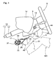
- the knee-protecting airbag device S is located below the steering column 9 and in front of a driver MD as an occupant for protecting knees K (KL and KR) of the driver MD.
- Up-down, left-right, and front-rear in this specification correspond to up-down, left-right, and front-rear of the vehicle with the airbag device mounted thereon.
- the steering column 9 includes a column body 10 connected to the steering wheel 8 and a column cover 13 covering the column body 10 below the steering wheel 8.
- the column body 10 includes a main shaft 11 and a column tube 12 covering the main shaft 11.
- the column cover 13 is made from synthetic resin into a generally square tubular shape, and is so located along the axial direction of the column body 10 as to cover the column body 10.
- a rear side 13a of the column cover 13 protruded from an instrument panel (as will be called “dashboard” herein below) 14 is formed into a generally curved rectangular plate shape ascending upward as it goes backward.
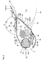
- the knee-protecting airbag device S includes a folded airbag 44, an inflator 37 for supplying the airbag 44 with inflation gas, a housing 17 opened rearward for housing the folded airbag 44 and the inflator 37, and an airbag cover 26 for covering rearward of an opening 18a of the housing 17.
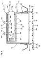
- the housing 17 is made of sheet metal. Referring to Figs. 2 to 4 , the housing 17 is located below the steering column 9, and includes a box-shaped main body 18 and a panel portion 23 extending outwardly from the main body 18.
- the main body 18 includes a generally square tubular circumferential wall portion 19, a bottom wall 21 for closing front side of the circumferential wall portion 19, and a generally rectangular opening 18a located at rear side.
- the circumferential wall portion 19 is provided, on outer surfaces of its walls 19a and 19b confronting each other in the vertical direction, with a plurality of retaining pawls 20 for attaching later-described upper and lower joint walls 29 and 30 of the airbag cover 26 to the housing 17.
- the retaining pawls 20 are formed as part of the panel portion 23, and are separate from the main body 18.
- Each of the retaining pawls 20 has a generally L-shaped section, and is adapted to be inserted into a retaining hole 29a or 30a in the joint wall 29 or 30 of the airbag cover 26, and retains a periphery of the retaining hole 29a or 30a.
- the circumferential wall portion 19 is further provided on one of its lateral side walls 19c with an insert hole 19d for inserting a later-described main body 38 of the inflator 37 therethrough.
- the bottom wall 21 is provided with two insert holes 21a for inserting bolts 39c of the inflator 37 thereinto.
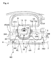
- the panel portion 23 is formed separately from the main body 18, and arranged to encircle the opening 18a of the housing 17. As shown in Fig. 4 , the panel portion 23 includes joint portions 24 for securing the housing 17 to the vehicle body 1. In the illustrated embodiment, the joint portions 24 are located in five positions of the panel portion 23: in two positions above the main body 18, in a position proximate to a left lower corner, and in positions proximate to upper and lower ends of right side.
- the vehicle body 1 includes brackets 4, 5, 6 and 7 for receiving the respective joint portions 24.
- the brackets 4 and 5 to which the joint portions 24A and 24B located in the upper side are joined extend from dashboard reinforcement 2 as part of the vehicle body 1.
- the brackets 6 and 7 to which the joint portions 24C and 24D located in the lower side are joined respectively extend from unillustrated center brace and front body pillar or the like as part of the vehicle body 1, respectively.
- the panel portion 23 further includes a slit 23a for inserting an upper side wall 29 of the airbag cover 26 thereinto, as shown in Fig. 2 .
- the airbag cover 26 is formed of thermo-plastic elastomer of olefin or the like, and is so attached to the housing 17 as to cover the rearward of the housing 17.
- the airbag cover 26 is located in part of a lower panel 14b of the dashboard 14 which is composed of an upper panel 14a and the lower panel 14b, and includes a door area 28 located in the vicinity of the opening 18a of the case 17, and a cover portion 27 located around the door area 28 for covering rearward of the panel portion 23.
- the door area 28 includes a pair of doors 35, and each one upper, lower, left and right side wall 29, 30, 31, and 32 that are located in a periphery of the doors 35.
- the pair of doors 35 is formed into a generally rectangular plate shape slightly larger than the opening 18a of the housing 17 , and covers the opening 18a.
- the doors 35 open in the vertical direction.
- Each of the doors 35 is provided at the upper or lower end with a hinge line 34 for the door to open around, and is provided, in a generally H-shaped portion in a circumference thereof as viewed from rearward, with a thinned breakable portion 33.
- the upper side wall 29, the lower side wall 30, the left side wall 31 and the right side wall 32 protrude forward to neighbor the circumferential wall portion 19 of the housing main body 18 from outside.
- the upper side wall 29 located close to the upper wall 19a of the circumferential wall portion 19 and the lower side wall 30 located close to the lower wall 19b serve as joint walls for attaching the airbag cover 26 to the housing 17.
- Each of the upper wall 29 and the lower wall 30 is provided with retaining holes 29a or 30a for retaining the retaining pawls 20.
- the inflator 37 is formed into a cylindrical shape which locates its axial direction along the vehicle's transverse direction.
- the inflator 37 includes a generally columnar body 38 and a diffuser 39.
- the inflator body 38 is provided at its one end (in a left end, in the illustrated embodiment) with a plurality of gas discharge ports 38a.
- the other end, or right end, is connected with a connector 41 from which a lead wire 42 for inputting actuating signals extends.
- the diffuser 39 includes a generally tubular holding tube 39a of sheet metal covering the inflator body 38, and a plurality of (two, in the illustrated embodiment) bolts 39c protruded from the holding tube 39a.
- the holding tube 39a is provided in its rear side face as mounted on the vehicle with a plurality of gas outlet ports 39b for emitting inflation gas discharged from the gas discharge ports 38a.
- the inflator 37 is actuated by an actuating signal inputted through the lead wire 42 when an airbag actuating circuit mounted on the vehicle detects a frontal collision of the vehicle. At this time, an unillustrated airbag device mounted on the steering wheel 8 is actuated simultaneously.
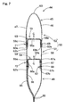
- the airbag 44 is formed of flexible woven fabric of polyester, polyamide or the like, and includes an airbag body 45 and two tethers 54 and 55 located inside the airbag body 45 for regulating a thickness of the airbag body 45 completely inflated.
- the airbag body 45 is formed into a generally rectangular plate shape when deployed completely, as shown in Figs. 5 and 6 , and includes an upstream part 49 which is located toward a lower end of the airbag body 45 as completely inflated, and a downstream part 50 which is located toward an upper end of the airbag body 45 as completely inflated.
- the upstream part 49 is located upstream, while the downstream part 50 is located downstream, in a stream of inflation gas.
- the downstream part 50 is adapted to protect an area from shins L to knees K of the driver MD as an occupant, when the airbag 44 is completely inflated, and has a lateral width capable of protecting the knees KL and KR of the driver MD (refer to Fig. 4 ).
- the airbag body 45 is a plane airbag constructed of an occupant side wall 46 deployed toward the occupant MD, and a vehicle body side wall 47 deployed toward the column cover 13, each upon airbag deployment.
- Each of the walls 46 and 47 has generally the same outer contour like a combination of a rectangle and a trapezoid.
- the upstream part 49 is held by the housing body 18 by means of the inflator 37, and its major part remains inside the housing body 18 when the airbag 44 is completely deployed.
- the insert holes 49a are for inserting the individual bolts 39c of the inflator 37 therethrough, whereas the slit 49b is for inserting the inflator body 38 therethrough.
- the airbag 44 is attached to the housing body 18 by that peripheries of the individual insert holes 49a are clamped between the holding tube 39a and the bottom wall 21 of the housing body 18 while the inflator body 38 is protruded from the slit 49b. As shown in Fig. 11 , an upper part 49d of the upstream part 49 protruded from the housing body 18 upon airbag deployment does not contact with legs or shins L of the occupant MD.
- the downstream part 50 protrudes, upon airbag inflation, rearward from the housing opening 18a, and is deployed between the occupant MD and the column cover 13 to protect an area from shins L to knees K of the occupant MD.
- the downstream part 50 includes a shin-protecting area 51 located immediately above the upstream part 49 for protecting shins L of the occupant MD, and a knee-protecting area 52 located above the shin-protecting area 51 or in upper end part of the airbag body 45 for protecting knees K of the occupant MD.
- the shin-protecting area 51 and the knee-protecting area 52 are partitioned by a tether (or partitioning tether) 55.
- the shin-protecting area 51 and the upstream part 49 are partitioned by a tether (regulating tether) 54.
- the tethers 54 and 55 are adapted to control the thickness of the airbag body 45 upon airbag inflation by joining the occupant side wall 46 and the vehicle body side wall 47 of the airbag body 45, and are arranged one above the other. As shown in Figs. 6 to 9 , each of the tethers 54 and 55 is sewn to all over inner circumference of the airbag body 45, and thus joined to the airbag body 45, along the transverse direction, in such a manner as to partition an inner space of the airbag body 45 in vertical direction. Each of the tethers 54 and 55 has a band shape, or a generally rectangular plate shape, elongated in transverse direction.
- the tether 54 serves as a regulating tether to partition the upstream part 49 and the shin-protecting area 51.
- the tether 54 is provided with gas communication holes 54a each serving as gas flow path that supply inflation gas G, which has flown into the upstream part 49, to the shin-protecting area 51.
- the gas communication holes 54a are located in two positions along transverse orientation in the vicinity of transverse center of the tether 54.
- a total of opening areas A1, or a sectional area of flow path, of the gas communication holes 54a (refer to Fig.
- the total of opening areas A1 of the gas communication holes 54a is so predetermined that an internal pressure of the shin-protecting area 51 peaks 5 to 15 ms (more desirably, 6 to 10 ms) later than the peak time of internal pressure of the upstream part 49.
- the time lag between the peak times of internal pressures of the shin-protecting area 51 and the upstream part 49 is less than 5 ms, the time lag is so small that the inflating shin-protecting area 51 may press shins L of an occupant MD. On the contrary, the time lag surpassing 15 ms may delay inflation of the downstream part 50, and hinder the knee-protecting area 52 from securing enough internal pressure, so that knees K of the occupant MD may not be protected properly.
- the tether 55 serves as a partitioning tether to partition the shin-protecting area 51 and the knee-protecting area 52 in a region of the downstream part 50.
- the tether 55 is provided with gas communication holes 55a each serving as gas flow path that supply inflation gas G, which has flown into the shin-protecting area 51, to the knee-protecting area 52.
- the gas communication holes 55a are located in three positions along transverse orientation. As viewed from above, one of the holes 55a is located between the gas communication holes 54a provided in the tether 54, and each of remaining two holes 55a is located in left and right side of each of the gas communication holes 54a (refer to Fig. 8 ).
- the gas communication holes 54a of the tether 54 and the gas communication holes 55a of the tether 55 are arranged in such a manner as dislocated from one another in transverse direction, as viewed from above.
- a total of opening areas A2 , or a sectional area of flow path, of the gas communication holes 55a (refer to Fig. 8 ) is predetermined greater than the total of opening areas A1 of the gas communication holes 54a in the tether 54. More specifically, a ratio of the total of opening areas A1 of the gas communication holes 54a to the total of opening areas A2 of the gas communication holes 55a is predetermined within a range of 0.1 to 0.4 (more desirably, 0.2 to 0.3).
- a capacity of the airbag body 45 is set for 15 to 20 liter, whereas an output of the inflator body 38 is set for 200 to 250 kPa/ft 3 (5.66 to 7.08 kPa/m 3 ).
- a capacity of the upstream part 49 is set for 5 to 8 liter, whereas a capacity of the downstream part 50 is set for 10 to 14 liter.
- a capacity of the shin-protecting area 51 is set for 3 to 6 liter, whereas a capacity of the knee-protecting area 52 is set for 7 to 10 liter.
- the total of opening areas A1 of the gas communication holes 54a in the tether 54 is set for 15 to 25 cm 2
- the total of opening areas A2 of the gas communication holes 55a in the tether 55 is set for 60 to 100 cm 2 .
- the airbag 44 completes inflation in a shorter time period than 30 ms, which is an usual time period from actuation of the inflator body 38 to contact of advancing knees K of occupant MD against a completely inflated airbag 44. Accordingly, the internal pressure of the knee-protecting area 52 is set to peak 22 to 26 ms after actuation of the inflator body 38.
- a vertical length L1 of the airbag body 45 is set for 450 to 470 mm
- a distance L2 from a lower edge of the upstream part 49 to the regulating tether 54 is set for 170 to 200 mm
- a distance L3 from the lower edge of the upstream part 49 to the partitioning tether 55 is set for 260 to 300 mm.
- a distance L4 between the lower edge of the upstream part 49 and an intersection P of an oblique side being an edge of the upstream part 49 and an edge of the downstream part 50 (or the knee-protecting area 52) is set for 215 to 235 mm.
- a transverse width W1 of the knee-protecting area 52 is set for 550 to 600 mm, whereas a transverse width W2 of lower edge part of the upstream part 49 is set for 275 to 305 mm.
- a width W3 of the regulating tether 54 is set for 50 to 60 mm, whereas a width W4 of the partitioning tether 55 is set for 50 to 80 mm, as shown in Fig. 10 .
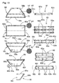
- the airbag 44 is formed by sewing up three bag body base cloths 58, 59 and 60, two tether base cloths 62 and 63, and three reinforcing cloths 65, 66 and 67 with sewing yarn 69, as shown in Fig. 10 .
- the bag body base cloths 58, 59 and 60, and the reinforcing cloth 66 is made of fabric coated by coating agent such as silicone, whereas the tether base cloths 62 and 63 and remaining reinforcing cloths 65 and 67 are made of fabric not coated by coating agent.
- the bag body base cloths 58 and 59 are to constitute the upstream part 49 and the shin-protecting area 51 of the downstream part 50, and have generally the same trapezoidal contour.
- the base cloth 58 is to constitute the occupant side wall 46 in the upstream part 49 and the shin-protecting area 51. Cutting of the base cloth 58 is made such that its warps VT and wefts HT intersect with vertical direction at an angle of 45°, respectively.
- the base cloth 59 is to constitute the vehicle body side wall 47 in the upstream part 49 and the shin-protecting area 51, and is provided with openings 59a and a slit 59b which are to serve as the insert holes 49a and the slit 49b, respectively.
- Cutting of the base cloth 59 is made such that its warps VT extend generally along vertical direction, whereas its wefts HT intersect with vertical direction at 90° .
- the base cloth 60 constitutes the occupant side wall 46 and the vehicle body side wall 47 in the knee-protecting area 52 of the downstream part 50, and has a generally rectangular shape. Cutting of the base cloth 60 is made such that its yarn direction intersects with yarn directions of each of the base cloths 58 and 59. Specifically, warps VT of the base cloth 60 intersect with vertical direction at an angle of 22.5°.
- the tether base cloth 62 is to constitute the regulating tether 54, and has a generally rectangular shape.
- the base cloth 62 is folded into two in the center vicinity of its width direction, on a fold extending along its longitudinal direction, and then sewn to the bag body base cloths 58 and 59 at edges in the twofold state, thereby forming the tether 54.
- the base cloth 62 is provided with four corresponding openings 62a to form the gas communication holes 54a. Each of the openings 62a has a generally circular shape.
- the tether base cloth 63 is to constitute the partitioning tether 55, and has a generally rectangular shape. As the base cloth 62, the base cloth 63 is folded into two in the center vicinity of its width direction, on a fold extending along its longitudinal direction, and then sewn to the bag body base cloths 58, 59 and 60 at edges in the twofold state, thereby forming the tether 55.
- the base cloth 63 is provided with six corresponding openings 63a to form the gas communication holes 55a. Each of the openings 63a has a generally oval shape.
- the reinforcing cloth 65 is to be arranged in inner side of lower part of the bag body base cloth 59, and is formed into a generally trapezoidal shape.
- the reinforcing cloth 65 is provided with openings 65b and a slit 65c each to constitute the insert holes 49a and the slit 49b.
- the cloth 65 also includes a projection 65a for reinforcing periphery of the slit 49b.
- the projection 65a is also provided with a slit 65d to constitute the slit 49b.
- the reinforcing cloth 66 is to be arranged in inner side of the reinforcing cloth 65, to cover a leading end part of, or a left half portion when mounted on vehicle, of, the inflator 37.
- the reinforcing cloth 66 is made of heat-resistant coated fabric so as to reduce damages caused by heat of inflation gas discharged from the gas discharge ports 38a of the inflator 37.
- the cloth 66 is provided with an opening 66c to constitute the insert hole 49a.
- the reinforcing cloth 67 is adapted to reinforce a joint of the tether 54 and the occupant side wall 46, and is formed into a band shape extending along transverse direction.
- the tether base cloth 63 is firstly folded back on a fold extending along its longitudinal direction, in the center vicinity of its width direction. Then edges in the width direction, or lower edges 60a and 60b of the bag body base cloth 60 are sewn to upper edges 58a and 59c of the bag body base cloths 58 and 59, respectively, with sewing yarn 69. Concurrently, the tether base cloth 63 in a twofold state is arranged in inner sides of the bag body base cloths 58 and 59, and then sewn to the base cloths 58 and 59 at edges 63b in the width direction. The lower edges 60a and 60b of the bag body base cloth 60 are disposed outsides of the upper edges 58a and 59c of the bag body base cloths 58 and 59, when the cloth 60 is sewn to the cloths 58 and 59.
- the reinforcing cloth 67 and the tether base cloth 62 which has been folded back on a fold extending along its longitudinal direction in the center vicinity of its width direction, are arranged in inner side of the body base cloth 58, and an upper edge 67a of the reinforcing cloth 67 is sewn to the base cloth 58 with sewing yarn 69, together with the tether base cloth 62. Subsequently, a lower edge 67b of the reinforcing cloth 67 is sewn to the base cloth 58 together with one edge 62b of the tether base cloth 62 in the width direction.
- the reinforcing cloth 65 is arranged in inner side of the bag body base cloth 59, and an upper edge 65e of the reinforcing cloth 65 is sewn to the base cloth 59 with sewing yarn 69 , together with the tether base cloth 62.
- the reinforcing cloth 66 is so located that its upper edge 66a is disposed between the reinforcing cloth 65 and the tether base cloth 62, and another edge 62b of the tether base cloth 62 in the width direction is sewn to the bag body base cloth 59 with sewing yarn 69, together with the upper edge 66a of the reinforcing cloth 66 and the reinforcing cloth 65.
- the projection 65a of the reinforcing cloth 65 is folded back inward, and an area around the slit 49b in the bag body base cloth 59, the reinforcing cloth 65 and the projection 65a, which are overlapped, is stitched up in a generally oval shape, thereby providing a reinforced area 49c.
- edges 60b in the longitudinal direction of the bag body base cloth 60, and remaining edges 58b and 59d of the base cloths 58 and 59 are sewn up with sewing yarn 69 together with edges 62b, 63b, 67c in the longitudinal direction of the tether base cloths 62, 63, and the reinforcing cloth 67, and remaining edges 65f and 66b of the reinforcing cloths 65 and 66, and thus the airbag 44 is completed.
- the openings 59a, 65b, 66a and the slits 59b, 65c and 65d to constitute the insert holes 49a and the slit 49b may be formed in the respective base cloths 59, 65 and 66 in advance. Alternatively, those openings may be formed by punching work or the like at a time, after joining the reinforcing cloths 65 and 66 to the bag body base cloth 59.
- the inflator 37 is housed within the airbag 44 with the bolts 39c projected from the insert holes 49a and the end of the inflator body 38 projected from the slit 49b. Then the airbag 44 is folded up, and an unillustrated breakable wrapping member is wrapped around the folded-up airbag 44 for keeping the folded-up configuration. At this time, the bolts 39c of the inflator 37 and the end of the inflator body 38 protruded from the insert holes 49a and the slit 49b are taken out from the wrapping member.
- the inflator 37 is housed in the housing body 18 together with the folded-up airbag 44 so that the individual bolts 39c of the inflator 37 are protruded from the insert holes 21a and nuts 40 fixed while the end of the inflator body 38 is protruded from the insert hole 19d.
- the airbag cover 26 is attached to the housing 17. More specifically, the upper side wall 29 is inserted into the slit 23a of the panel portion 23, and the airbag cover 26 is moved toward the housing 17. Then the individual retaining pawls 20 are so inserted into the retaining holes 29a and 30a of the upper side wall 29 and the lower side wall 30 as to be retained by peripheries of the retaining holes 29a and 30a. Thus the airbag cover 26 is attached to the housing 17.
- the individual joint portions 24 of the housing 17 are secured to the vehicle body 1 utilizing the brackets 4, 5, 6 and 7, whereas the connector 41 having the lead wire 42 joined thereto is connected to the inflator body 38. If the dashboard 14 and an under cover 12, as shown in Figs. 1 and 2 , are then attached, the airbag device S is mounted on the vehicle.
- the airbag device S After the airbag device S is mounted on the vehicle, if an actuating signal is inputted to the inflator body 38 via the lead wire 42, inflation gas is discharged from the gas discharge ports 38a of the inflator 37, and the gas then flows into the airbag 44 via the gas outlet ports 39b of the diffuser 39. Then the airbag 44 inflates and breaks the wrapping member, pushes the doors 35 of the airbag cover 26, and breaks the breakable portion 33 to open the doors 35 vertically around the hinge lines 34, and thus the airbag 44 deploys as indicated by double-dotted lines in Figs. 1 and 4 , and solid lines in Fig. 11 .
- the shin-protecting area 51 which is adapted to protect shins L of an occupant MD when completely inflated, peaks 5 to 15 ms later than the peak time of internal pressure of the upstream part 49. This means that the internal pressure in the downstream part 50 rises gradually in the course of inflation. Accordingly, even when the airbag 44 inflates in a condition that legs (especially, shins L) of the occupant MD are located proximate to the column cover 13 , the shin-protecting area 51 of the downstream part 50 does not press the shins L unduly during inflation, so that the shins L of the occupant MD are protected softly.
- the time lag between the peak times of internal pressures of the shin-protecting area 51 and the upstream part 49 is less than 5 ms, the time lag is so small that the inflating shin-protecting area 51 may press shins L of the occupant MD. On the contrary, the time lag surpassing 15 ms may delay inflation of the downstream part 50, and hinder the knee-protecting area 52 from securing enough internal pressure, so that knees K of the occupant MD may not be protected properly.
- Fig. 12A shows a graph of measurements of internal pressure of the airbag 44 used in the knee-protecting airbag device S of the foregoing embodiment, in inflation.
- each length L1-L4 of individual part is set for: L1: 470 mm, L2: 200mm, L3: 300mm, and L4: 235 mm.
- Each width W1-W4 of individual part is set for: W1 : 600 mm, W2: 305mm, W3: 50mm, and W4: 80 mm.
- the capacity of the airbag body 45 is set for 18 liter (the downstream part 50: 13 liter, the shin-protecting area 51: 3 liter, and the knee-protecting area 52: 10 liter), whereas a total of opening areas A1 of the gas communication holes 54a in the regulating tether 54 is set for 19.2 cm 2 , and a total of opening areas A2 of the gas communication holes 55a in the partitioning tether 55 is set for 93.2 cm 2 .
- This graph shows that internal pressure of the upstream part 49 rises steeply at first when inflation gas is discharged from the inflator 37 in the airbag 44 of the airbag device S according to the foregoing embodiment.
- internal pressure of the shin-protecting area 51 is in a gradual rise.
- Internal pressure of the shin-protecting area 51 peaks at around 21 ms when the internal pressure of the upstream part 49 turns to steep decline, and about 8 ms passed from peak time of the internal pressure of the upstream part 49 , and then the internal pressure of the knee-protecting area 52 peaks at around 25 ms.
- the shin-protecting area 51 of the downstream part 50 does not press the shins L unduly during inflation, so that the shins L of the occupant MD are protected softly.
- the internal pressure of the upstream part 49 rises steeply in the initial stage of inflation, major part of the upstream part 49 remains inside the housing body 18 when the airbag 44 is completely inflated, as shown in Fig. 11 .
- an upper part 49d of the upstream part 49 protruded from the housing body 18 does not contact with legs of the occupant MD, also as shown in Fig. 11 . Therefore, the shins L of the occupant MD are smoothly protected even if the internal pressure of the upstream part 49 rises.
- FIG. 12B shows measurement results of internal pressure of a comparative example.
- An airbag body 45' used as a comparative example is set to have the same capacity as the airbag body 45 in the airbag 44.
- the airbag body 45' is provided with a regulating tether 54' and a partitioning tether 55' disposed one above the other.
- Each of the tethers 54' and 55' is arranged in such a manner as to leave a gap between itself and left or right edge of the airbag body 45', and the regulating tether 54' disposed in lower side is provided, in its center vicinity, with a gas communication hole 54a' for sending inflation gas toward a shin-protecting area from a upstream part.
- a gas communication hole 54a' for sending inflation gas toward a shin-protecting area from a upstream part.
- the time lag between the peak times of internal pressures of the upstream part 49 and the shin-protecting area 51 is caused by the opening area A1 (or sectional area of flow path) of the gas communication holes 54a that are formed in the regulating tether 54 located between the upstream part 49 and the downstream part 50.
- This construction is easily made merely by a design change of a tether of airbag which has been conventionally used in a knee-protecting airbag device, which contributes to reduce manufacturing cost and number of parts.
- the time lag between the peak times of internal pressures of the upstream part and the shin-protecting area may be adjusted by, for example, adjusting output of inflator which discharges inflation gas.
- the regulating tether 54 is joined to all over inner circumference of the airbag body 45, and includes the gas communication holes 54a through which inflation gas passes. That is, the upstream part 49 and the shin-protecting area 51 is partitioned by the regulating tether 54, and inflation gas G fed to the upstream part 49 then flows into the shin-protecting area 51 in the downstream part 50 via the communication holes 54a in the regulating tether 54.
- inflation gas G comes to enter into the shin-protecting area 51 in a phase the upstream part 49 has completed inflation partway, and thus the peak time of internal pressure of the shin-protecting area 51 is securely delayed than the peak time of internal pressure of the upstream part 49.
- the upstream part 49 expands widely in transverse direction in the initial stage of airbag inflation. Accordingly, expansion of the downstream part 50 thereafter goes smoothly.
- the downstream part 50 includes the partitioning tether 55 partitioning the shin-protecting area 51 and the knee-protecting area 52
- thickness of the downstream part 50 during airbag inflation is controlled by the partitioning tether 55, and the shin-protecting area 51 is prevented from inflating thickly in such a manner as to press shins L of an occupant MD.
- the total of opening areas A1 of the gas communication holes 54a in the regulating tether 54 is set smaller than the total of opening areas A2 of the gas communication holes 55a in the partitioning tether 55, the peak time of internal pressure of the shin-protecting area 51 is securely delayed.
- the regulating tether 54 and the partitioning tether 55 are respectively joined to all over inner circumference of the airbag body 45, and include the gas communication holes 54a/55a through which inflation gas passes. That is, flow path of inflation gas is constituted by the gas communication holes 54a and 55a formed in the tethers 54 and 55.
- sectional area of gas flow path can be adjusted by merely changing opening area of each of the gas communication holes 54a and 55a, and setting of the sectional area of flow path is facilitated in comparison with a case in which, for example, a tether is joined to part of an airbag body, not to all over inner circumference thereof , such that a gas flow path is provided between a base cloth forming the airbag body and the tether.
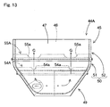
- each of gas communication holes 54a in a regulating tether 54A and each of gas communication holes 55a in a partitioning tether 55A are arranged in series with each other in vertical direction, as in an airbag 44A shown in Fig. 13 .
- inflation gas G flown into a shin-protecting area 51 from an upstream part 49 via the communication holes 54a directly reaches upper end of a knee-protecting area 52, via the communication holes 55a arranged in series with the communication holes 54a, and therefore, the knee-protecting area 52 inflates swiftly.
- the airbag body in the foregoing embodiment includes two tethers 54 and 55
- the number of tethers should not be limited thereby, but more than one tether may be disposed in an area of the downstream part 50.
- shape of the tethers should not be limited thereby.
- a base cloth having such a contour as the tether base cloth 62 or 63 is split up in the vicinity of its fold line (i.e., the same contour as the tether) may be used in two-ply state as the tether.
- the present invention may naturally be applied to a knee-protecting airbag device for front passenger's seat located in front of front passenger's seat for protecting knees of a passenger seated in front passenger's seat.
Landscapes
- Engineering & Computer Science (AREA)
- Mechanical Engineering (AREA)
- Air Bags (AREA)
Applications Claiming Priority (1)
| Application Number | Priority Date | Filing Date | Title |
|---|---|---|---|
| JP2004325238A JP4345645B2 (ja) | 2004-11-09 | 2004-11-09 | 膝保護用エアバッグ装置 |
Publications (2)
| Publication Number | Publication Date |
|---|---|
| EP1655183A1 EP1655183A1 (en) | 2006-05-10 |
| EP1655183B1 true EP1655183B1 (en) | 2010-02-24 |
Family
ID=35677313
Family Applications (1)
| Application Number | Title | Priority Date | Filing Date |
|---|---|---|---|
| EP05024007A Ceased EP1655183B1 (en) | 2004-11-09 | 2005-11-03 | Knee-protecting airbag device |
Country Status (5)
| Country | Link |
|---|---|
| US (1) | US7434837B2 (enExample) |
| EP (1) | EP1655183B1 (enExample) |
| JP (1) | JP4345645B2 (enExample) |
| CN (2) | CN100425480C (enExample) |
| DE (1) | DE602005019516D1 (enExample) |
Families Citing this family (64)
| Publication number | Priority date | Publication date | Assignee | Title |
|---|---|---|---|---|
| JP4345645B2 (ja) * | 2004-11-09 | 2009-10-14 | 豊田合成株式会社 | 膝保護用エアバッグ装置 |
| JP5053520B2 (ja) * | 2005-04-20 | 2012-10-17 | 日本プラスト株式会社 | エアバッグ |
| JP5219060B2 (ja) * | 2005-11-02 | 2013-06-26 | タカタ株式会社 | エアバッグ装置 |
| JP4911492B2 (ja) * | 2006-01-18 | 2012-04-04 | タカタ株式会社 | エアバッグ及びエアバッグ装置 |
| FR2900111B1 (fr) * | 2006-04-24 | 2011-02-11 | Trw Automotive Gmbh | Dispositif de retenue d'occupant de vehicule avec coussin a gaz. |
| JP4793104B2 (ja) * | 2006-06-01 | 2011-10-12 | 豊田合成株式会社 | サイドエアバッグ装置 |
| JP4235221B2 (ja) * | 2006-11-02 | 2009-03-11 | トヨタ自動車株式会社 | コラム付けニーエアバッグ装置 |
| US20080116669A1 (en) * | 2006-11-14 | 2008-05-22 | Toyoda Gosei Co., Ltd. | Knee-protecting airbag device |
| JP2008149965A (ja) * | 2006-12-19 | 2008-07-03 | Toyoda Gosei Co Ltd | エアバッグ装置 |
| JP2009083550A (ja) * | 2007-09-27 | 2009-04-23 | Toyoda Gosei Co Ltd | 膝保護エアバッグ |
| EP2042387B1 (en) | 2007-09-27 | 2012-02-01 | Toyoda Gosei Co., Ltd. | Airbag for knee protection |
| JP4530018B2 (ja) * | 2007-09-27 | 2010-08-25 | 豊田合成株式会社 | 膝保護エアバッグ |
| JP5196530B2 (ja) * | 2007-10-22 | 2013-05-15 | 芦森工業株式会社 | 膝保護用エアバッグ装置 |
| US8096578B2 (en) * | 2007-11-02 | 2012-01-17 | Tk Holdings Inc. | Knee airbag |
| US8231137B2 (en) * | 2007-11-09 | 2012-07-31 | Toyota Motor Engineering & Manufacturing North America, Inc. | Knee airbag housing assembly |
| JP4975598B2 (ja) * | 2007-12-10 | 2012-07-11 | 日本プラスト株式会社 | ニーエアバッグ装置 |
| EP2072348B1 (en) * | 2007-12-18 | 2016-10-05 | Autoliv Development AB | Knee airbag and method of folding the same |
| KR100947997B1 (ko) * | 2007-12-18 | 2010-03-18 | 델파이코리아 유한회사 | 자동차용 에어백 접는 방법 |
| US8444177B2 (en) * | 2008-02-25 | 2013-05-21 | Autoliv Development Ab | Assembly with an instrument panel for a motor vehicle and a knee airbag |
| JP4877280B2 (ja) * | 2008-06-09 | 2012-02-15 | 豊田合成株式会社 | 膝保護エアバッグ |
| JP4591574B2 (ja) * | 2008-08-06 | 2010-12-01 | トヨタ自動車株式会社 | 車両用ニーエアバッグ装置 |
| JP4952694B2 (ja) * | 2008-09-25 | 2012-06-13 | 豊田合成株式会社 | エアバッグ |
| JP5201090B2 (ja) * | 2008-09-30 | 2013-06-05 | 豊田合成株式会社 | エアバッグ |
| US8777262B2 (en) | 2009-04-27 | 2014-07-15 | Autoliv Asp, Inc. | Airbag assemblies with stabilizer straps |
| US8500157B2 (en) | 2009-04-27 | 2013-08-06 | Autoliv Asp, Inc. | Knee airbag assemblies and related methods |
| US8118325B2 (en) * | 2009-04-27 | 2012-02-21 | Autoliv Asp, Inc. | Inflatable knee airbags and internal tethers produced from single panels of material |
| US8083254B2 (en) | 2009-04-27 | 2011-12-27 | Autoliv Asp, Inc. | Knee airbag assemblies configured for inflator insertion and inflator-mediated coupling to an airbag housing |
| US20100270782A1 (en) * | 2009-04-27 | 2010-10-28 | Autoliv Asp, Inc. | Inflatable knee airbag assemblies with bag straps for wrapping the airbags and optimizing deployment |
| JP2009208772A (ja) * | 2009-05-22 | 2009-09-17 | Toyoda Gosei Co Ltd | 膝保護用エアバッグ装置 |
| US8297649B2 (en) | 2009-07-16 | 2012-10-30 | Autoliv Asp, Inc. | Inflatable knee airbag having two chambers separated by an internal tether |
| US8505969B2 (en) * | 2009-10-27 | 2013-08-13 | Tk Holdings Inc. | Knee airbag module |
| US8272667B2 (en) * | 2009-11-03 | 2012-09-25 | Autoliv Asp, Inc. | Low-mount inflatable knee airbags having serial chambers |
| EP2499029B1 (en) | 2009-11-10 | 2014-01-08 | Toyoda Gosei Co., Ltd. | Wrap-around airbag device |
| US8500155B2 (en) | 2009-12-22 | 2013-08-06 | Autoliv Asp, Inc. | Inflatable airbag assembly with an integral cover |
| US8651513B2 (en) * | 2010-02-17 | 2014-02-18 | Autoliv Development Ab | Airbag |
| US8500161B2 (en) * | 2010-03-31 | 2013-08-06 | Tk Holdings Inc. | Knee airbag |
| DE102010018180B4 (de) * | 2010-04-22 | 2016-12-08 | Autoliv Development Ab | Gassack mit einer ersten Seitenwand und einer zweiten Seitenwand und wenigstens einem Fangband |
| US8360464B2 (en) | 2010-08-31 | 2013-01-29 | Autoliv Asp, Inc. | Covers for inflatable knee airbag housings |
| US8297650B2 (en) | 2010-08-31 | 2012-10-30 | Autoliv Asp, Inc. | Inflatable knee airbag assemblies with articulating housings |
| KR101169570B1 (ko) | 2010-09-30 | 2012-07-31 | 에스앤티모티브 주식회사 | 무릎 에어백장치 |
| CN102275560B (zh) * | 2010-11-15 | 2012-12-19 | 芜湖金安世腾汽车安全系统有限公司 | 一种车辆用乘员腿部保护装置 |
| US8540276B2 (en) | 2011-11-07 | 2013-09-24 | Autoliv Asp, Inc. | Inflatable knee airbag assemblies with cushion fold pattern |
| US8505963B1 (en) | 2012-02-24 | 2013-08-13 | Autoliv Asp, Inc. | Airbag assemblies with strap clamps |
| KR101520850B1 (ko) * | 2012-03-05 | 2015-05-20 | 아우토리브 디벨롭먼트 아베 | 무릎 에어백 쿠션의 제조 방법 |
| JP5915481B2 (ja) * | 2012-09-27 | 2016-05-11 | 豊田合成株式会社 | エアバッグ装置 |
| DE102013003239B4 (de) | 2013-02-27 | 2019-03-21 | Autoliv Development Ab | Knieairbag |
| US9010804B2 (en) | 2013-03-15 | 2015-04-21 | Autoliv Asp, Inc. | Airbag assemblies with constrained stabilizer straps |
| CN103496351A (zh) * | 2013-09-17 | 2014-01-08 | 锦州锦恒汽车安全系统有限公司 | 汽车膝部气囊气袋 |
| CN104742849B (zh) * | 2015-03-18 | 2017-08-25 | 延锋百利得(上海)汽车安全系统有限公司 | 一种膝部安全气囊装置 |
| JP6507797B2 (ja) * | 2015-03-31 | 2019-05-08 | 豊田合成株式会社 | 膝保護用エアバッグ装置 |
| JP6507798B2 (ja) * | 2015-03-31 | 2019-05-08 | 豊田合成株式会社 | 膝保護用エアバッグ装置 |
| JP6413934B2 (ja) | 2015-06-03 | 2018-10-31 | マツダ株式会社 | 乗員保護装置の配設構造 |
| KR102440403B1 (ko) * | 2015-09-09 | 2022-09-05 | 현대모비스 주식회사 | 무릎 에어백 장치 및 무릎 에어백 장치의 제조방법 |
| JP6442775B2 (ja) * | 2016-05-12 | 2018-12-26 | 本田技研工業株式会社 | 乗員保護装置 |
| US10960845B2 (en) * | 2016-10-10 | 2021-03-30 | Key Safety Systems, Inc. | Curved airbag and method of manufacturing |
| JP6740947B2 (ja) * | 2017-03-30 | 2020-08-19 | 豊田合成株式会社 | エアバッグ装置 |
| JP6962737B2 (ja) * | 2017-08-21 | 2021-11-05 | 豊田合成株式会社 | エアバッグ装置 |
| US10696266B2 (en) | 2017-11-10 | 2020-06-30 | Autoliv Asp, Inc. | Inflatable knee airbag assemblies |
| JP7087814B2 (ja) * | 2018-08-10 | 2022-06-21 | トヨタ自動車株式会社 | 車室前部構造 |
| DE102018124104B4 (de) * | 2018-09-28 | 2020-12-10 | Autoliv Development Ab | Gassack mit einem Klemmbereich und Verfahren zum Formen eines Gassackpaketes |
| DE102019208417A1 (de) * | 2019-06-11 | 2020-12-17 | Audi Ag | Beinschutzvorrichtung für ein Insassenschutzsystem eines Fahrzeugs |
| US11685328B2 (en) | 2021-04-29 | 2023-06-27 | Ford Global Technologies, Llc | Airbag having multiple inflation chambers supported on a dash |
| JP2025056943A (ja) * | 2023-09-27 | 2025-04-09 | 豊田合成株式会社 | エアバッグ装置用ヒータ |
| US12257971B1 (en) * | 2023-10-17 | 2025-03-25 | Autoliv Asp, Inc. | Knee airbag for a vehicle |
Family Cites Families (27)
| Publication number | Priority date | Publication date | Assignee | Title |
|---|---|---|---|---|
| US4262931A (en) * | 1979-09-18 | 1981-04-21 | Ford Motor Company | Air bag restraint system |
| DE4443027A1 (de) * | 1994-12-02 | 1996-06-05 | Trw Repa Gmbh | Seitenaufprall-Gassack |
| DE19538657A1 (de) * | 1995-10-17 | 1997-04-24 | Trw Repa Gmbh | Gassack-Seitenaufprall-Schutzeinrichtung |
| US5697641A (en) * | 1996-05-14 | 1997-12-16 | Trw Vehicle Safety Systems Inc. | Inflatable vehicle occupant protection device and method of inflating the device |
| US5853191A (en) * | 1997-02-06 | 1998-12-29 | Alliedsignal Inc. | Vehicle restraint system with inflation control |
| US5845935A (en) * | 1997-03-07 | 1998-12-08 | Morton International, Inc. | Side airbag module |
| DE19946477B4 (de) * | 1999-09-28 | 2010-09-02 | Takata-Petri Ag | Airbag-Anordnung |
| EP1122134B1 (en) * | 2000-02-01 | 2005-02-16 | Delphi Automotive Systems Sungwoo Co., Ltd. | Side airbag system and method for manufacturing the same |
| US6450529B1 (en) * | 2000-06-23 | 2002-09-17 | Breed Automotive Technologies, Inc. | Inflatable side air bag curtain module with chamber separators |
| JP3868226B2 (ja) | 2001-05-21 | 2007-01-17 | 豊田合成株式会社 | 膝保護用エアバッグ装置 |
| US6945557B2 (en) * | 2001-11-09 | 2005-09-20 | Toyoda Gosei Co., Ltd. | Knee protecting airbag device |
| JP3912144B2 (ja) * | 2001-05-21 | 2007-05-09 | タカタ株式会社 | 助手席用乗員脚部保護装置 |
| US6752417B2 (en) * | 2001-05-21 | 2004-06-22 | Toyoda Gosei Co., Ltd. | Knee protecting airbag device |
| US6715789B2 (en) * | 2001-05-21 | 2004-04-06 | Toyoda Gosei Co., Ltd. | Knee protecting airbag device |
| EP1852317A1 (en) * | 2001-07-03 | 2007-11-07 | Delphi Korea Corporation | Side airbag for automobile and method of folding the same |
| JP3687602B2 (ja) * | 2001-12-10 | 2005-08-24 | トヨタ自動車株式会社 | 車両用乗員膝部保護装置 |
| JP3948332B2 (ja) * | 2002-04-15 | 2007-07-25 | タカタ株式会社 | 乗員脚部保護装置 |
| JP2004284416A (ja) * | 2003-03-19 | 2004-10-14 | Toyoda Gosei Co Ltd | 膝保護用エアバッグ装置 |
| US6854759B2 (en) * | 2003-04-09 | 2005-02-15 | Trw Vehicle Safety Systems Inc. | Apparatus including an inflatable knee bag |
| US7350801B2 (en) * | 2003-07-11 | 2008-04-01 | Toyoda Gosei Co., Ltd. | Knee-protecting airbag |
| JP2005178607A (ja) * | 2003-12-19 | 2005-07-07 | Takata Corp | ニーバッグ及び乗員脚部保護装置 |
| US20050151351A1 (en) * | 2004-01-12 | 2005-07-14 | Enders Mark L. | Fabric knee airbag for high internal pressures |
| JP4534525B2 (ja) * | 2004-02-27 | 2010-09-01 | タカタ株式会社 | ニーバッグ及び乗員脚部保護装置 |
| JP4424048B2 (ja) * | 2004-04-20 | 2010-03-03 | タカタ株式会社 | ニーバッグモジュール |
| JP4345645B2 (ja) * | 2004-11-09 | 2009-10-14 | 豊田合成株式会社 | 膝保護用エアバッグ装置 |
| JP4665669B2 (ja) * | 2005-08-30 | 2011-04-06 | タカタ株式会社 | 乗員脚部拘束装置 |
| JP4793910B2 (ja) * | 2005-10-24 | 2011-10-12 | タカタ株式会社 | 乗員脚部拘束装置 |
-
2004
- 2004-11-09 JP JP2004325238A patent/JP4345645B2/ja not_active Expired - Fee Related
-
2005
- 2005-11-03 EP EP05024007A patent/EP1655183B1/en not_active Ceased
- 2005-11-03 DE DE602005019516T patent/DE602005019516D1/de not_active Expired - Lifetime
- 2005-11-03 US US11/265,501 patent/US7434837B2/en active Active
- 2005-11-09 CN CNB2005101156605A patent/CN100425480C/zh not_active Expired - Fee Related
- 2005-11-09 CN CN2008100981026A patent/CN101269647B/zh not_active Expired - Fee Related
Also Published As
| Publication number | Publication date |
|---|---|
| JP4345645B2 (ja) | 2009-10-14 |
| JP2006131186A (ja) | 2006-05-25 |
| CN1772536A (zh) | 2006-05-17 |
| CN100425480C (zh) | 2008-10-15 |
| DE602005019516D1 (de) | 2010-04-08 |
| CN101269647B (zh) | 2011-02-16 |
| US7434837B2 (en) | 2008-10-14 |
| US20060108780A1 (en) | 2006-05-25 |
| CN101269647A (zh) | 2008-09-24 |
| EP1655183A1 (en) | 2006-05-10 |
Similar Documents
| Publication | Publication Date | Title |
|---|---|---|
| EP1655183B1 (en) | Knee-protecting airbag device | |
| US7232149B2 (en) | Knee protection airbag apparatus | |
| JP3782793B2 (ja) | 改良型のカーテンエアバッグ組立体 | |
| US8696020B2 (en) | Airbag apparatus | |
| US8006999B2 (en) | Head protection airbag | |
| US7891700B2 (en) | Airbag for knee protection | |
| US7083189B2 (en) | Airbag for head protection | |
| US7530597B2 (en) | Airbag device for front passenger's seat | |
| US7163233B2 (en) | Head-protecting airbag | |
| US7350801B2 (en) | Knee-protecting airbag | |
| JP2007331402A (ja) | 側突用エアバッグ、側突用エアバッグ装置、車両用シート | |
| JP5232422B2 (ja) | 側突用エアバッグ、側突用エアバッグ装置、車両用シート | |
| JP4140494B2 (ja) | 膝保護用エアバッグ装置 | |
| US7748730B2 (en) | Airbag system | |
| JP2005096625A (ja) | 膝保護用エアバッグ装置 | |
| WO2007083422A1 (ja) | エアバッグ及びエアバッグ装置 | |
| JP4063168B2 (ja) | 膝保護用エアバッグ | |
| US7614649B2 (en) | Airbag system | |
| JP2020026254A (ja) | エアバッグ | |
| JP2009208772A (ja) | 膝保護用エアバッグ装置 | |
| JP2007045173A (ja) | 頭部保護エアバッグ | |
| EP1777122B1 (en) | Airbag system | |
| JP5918754B2 (ja) | エアバッグ装置 | |
| JP2007261505A (ja) | 助手席用エアバッグ |
Legal Events
| Date | Code | Title | Description |
|---|---|---|---|
| PUAI | Public reference made under article 153(3) epc to a published international application that has entered the european phase |
Free format text: ORIGINAL CODE: 0009012 |
|
| 17P | Request for examination filed |
Effective date: 20051103 |
|
| AK | Designated contracting states |
Kind code of ref document: A1 Designated state(s): AT BE BG CH CY CZ DE DK EE ES FI FR GB GR HU IE IS IT LI LT LU LV MC NL PL PT RO SE SI SK TR |
|
| AX | Request for extension of the european patent |
Extension state: AL BA HR MK YU |
|
| AKX | Designation fees paid |
Designated state(s): DE FR GB |
|
| 17Q | First examination report despatched |
Effective date: 20061221 |
|
| 17Q | First examination report despatched |
Effective date: 20061221 |
|
| GRAP | Despatch of communication of intention to grant a patent |
Free format text: ORIGINAL CODE: EPIDOSNIGR1 |
|
| GRAS | Grant fee paid |
Free format text: ORIGINAL CODE: EPIDOSNIGR3 |
|
| GRAA | (expected) grant |
Free format text: ORIGINAL CODE: 0009210 |
|
| AK | Designated contracting states |
Kind code of ref document: B1 Designated state(s): DE FR GB |
|
| REG | Reference to a national code |
Ref country code: GB Ref legal event code: FG4D |
|
| REF | Corresponds to: |
Ref document number: 602005019516 Country of ref document: DE Date of ref document: 20100408 Kind code of ref document: P |
|
| PLBE | No opposition filed within time limit |
Free format text: ORIGINAL CODE: 0009261 |
|
| STAA | Information on the status of an ep patent application or granted ep patent |
Free format text: STATUS: NO OPPOSITION FILED WITHIN TIME LIMIT |
|
| 26N | No opposition filed |
Effective date: 20101125 |
|
| REG | Reference to a national code |
Ref country code: GB Ref legal event code: 746 Effective date: 20130920 |
|
| REG | Reference to a national code |
Ref country code: DE Ref legal event code: R084 Ref document number: 602005019516 Country of ref document: DE Effective date: 20130919 |
|
| REG | Reference to a national code |
Ref country code: FR Ref legal event code: PLFP Year of fee payment: 11 |
|
| REG | Reference to a national code |
Ref country code: FR Ref legal event code: PLFP Year of fee payment: 12 |
|
| REG | Reference to a national code |
Ref country code: FR Ref legal event code: PLFP Year of fee payment: 13 |
|
| REG | Reference to a national code |
Ref country code: FR Ref legal event code: PLFP Year of fee payment: 14 |
|
| PGFP | Annual fee paid to national office [announced via postgrant information from national office to epo] |
Ref country code: GB Payment date: 20230928 Year of fee payment: 19 |
|
| PGFP | Annual fee paid to national office [announced via postgrant information from national office to epo] |
Ref country code: FR Payment date: 20230929 Year of fee payment: 19 |
|
| PGFP | Annual fee paid to national office [announced via postgrant information from national office to epo] |
Ref country code: DE Payment date: 20230929 Year of fee payment: 19 |
|
| REG | Reference to a national code |
Ref country code: DE Ref legal event code: R119 Ref document number: 602005019516 Country of ref document: DE |
|
| GBPC | Gb: european patent ceased through non-payment of renewal fee |
Effective date: 20241103 |
|
| PG25 | Lapsed in a contracting state [announced via postgrant information from national office to epo] |
Ref country code: DE Free format text: LAPSE BECAUSE OF NON-PAYMENT OF DUE FEES Effective date: 20250603 |
|
| PG25 | Lapsed in a contracting state [announced via postgrant information from national office to epo] |
Ref country code: GB Free format text: LAPSE BECAUSE OF NON-PAYMENT OF DUE FEES Effective date: 20241103 |
|
| PG25 | Lapsed in a contracting state [announced via postgrant information from national office to epo] |
Ref country code: FR Free format text: LAPSE BECAUSE OF NON-PAYMENT OF DUE FEES Effective date: 20241130 |