EP1655177A1 - Befestigungsvorrichtung für einen Monitor an einem Fahrzeugsitz - Google Patents
Befestigungsvorrichtung für einen Monitor an einem Fahrzeugsitz Download PDFInfo
- Publication number
- EP1655177A1 EP1655177A1 EP05021550A EP05021550A EP1655177A1 EP 1655177 A1 EP1655177 A1 EP 1655177A1 EP 05021550 A EP05021550 A EP 05021550A EP 05021550 A EP05021550 A EP 05021550A EP 1655177 A1 EP1655177 A1 EP 1655177A1
- Authority
- EP
- European Patent Office
- Prior art keywords
- monitor
- fastening device
- seat
- leg
- seat back
- Prior art date
- Legal status (The legal status is an assumption and is not a legal conclusion. Google has not performed a legal analysis and makes no representation as to the accuracy of the status listed.)
- Granted
Links
Images


Classifications
-
- B—PERFORMING OPERATIONS; TRANSPORTING
- B60—VEHICLES IN GENERAL
- B60R—VEHICLES, VEHICLE FITTINGS, OR VEHICLE PARTS, NOT OTHERWISE PROVIDED FOR
- B60R11/00—Arrangements for holding or mounting articles, not otherwise provided for
- B60R11/02—Arrangements for holding or mounting articles, not otherwise provided for for radio sets, television sets, telephones, or the like; Arrangement of controls thereof
- B60R11/0229—Arrangements for holding or mounting articles, not otherwise provided for for radio sets, television sets, telephones, or the like; Arrangement of controls thereof for displays, e.g. cathodic tubes
- B60R11/0235—Arrangements for holding or mounting articles, not otherwise provided for for radio sets, television sets, telephones, or the like; Arrangement of controls thereof for displays, e.g. cathodic tubes of flat type, e.g. LCD
-
- B—PERFORMING OPERATIONS; TRANSPORTING
- B60—VEHICLES IN GENERAL
- B60R—VEHICLES, VEHICLE FITTINGS, OR VEHICLE PARTS, NOT OTHERWISE PROVIDED FOR
- B60R11/00—Arrangements for holding or mounting articles, not otherwise provided for
- B60R2011/0001—Arrangements for holding or mounting articles, not otherwise provided for characterised by position
- B60R2011/0003—Arrangements for holding or mounting articles, not otherwise provided for characterised by position inside the vehicle
- B60R2011/0012—Seats or parts thereof
- B60R2011/0015—Back-rests
-
- B—PERFORMING OPERATIONS; TRANSPORTING
- B60—VEHICLES IN GENERAL
- B60R—VEHICLES, VEHICLE FITTINGS, OR VEHICLE PARTS, NOT OTHERWISE PROVIDED FOR
- B60R11/00—Arrangements for holding or mounting articles, not otherwise provided for
- B60R2011/0001—Arrangements for holding or mounting articles, not otherwise provided for characterised by position
- B60R2011/0003—Arrangements for holding or mounting articles, not otherwise provided for characterised by position inside the vehicle
- B60R2011/0012—Seats or parts thereof
- B60R2011/0017—Head-rests
-
- B—PERFORMING OPERATIONS; TRANSPORTING
- B60—VEHICLES IN GENERAL
- B60R—VEHICLES, VEHICLE FITTINGS, OR VEHICLE PARTS, NOT OTHERWISE PROVIDED FOR
- B60R11/00—Arrangements for holding or mounting articles, not otherwise provided for
- B60R2011/0042—Arrangements for holding or mounting articles, not otherwise provided for characterised by mounting means
- B60R2011/0049—Arrangements for holding or mounting articles, not otherwise provided for characterised by mounting means for non integrated articles
- B60R2011/005—Connection with the vehicle part
- B60R2011/0052—Connection with the vehicle part using screws, bolts, rivets or the like
-
- B—PERFORMING OPERATIONS; TRANSPORTING
- B60—VEHICLES IN GENERAL
- B60R—VEHICLES, VEHICLE FITTINGS, OR VEHICLE PARTS, NOT OTHERWISE PROVIDED FOR
- B60R11/00—Arrangements for holding or mounting articles, not otherwise provided for
- B60R2011/0042—Arrangements for holding or mounting articles, not otherwise provided for characterised by mounting means
- B60R2011/0049—Arrangements for holding or mounting articles, not otherwise provided for characterised by mounting means for non integrated articles
- B60R2011/005—Connection with the vehicle part
- B60R2011/0059—Connection with the vehicle part using clips, clamps, straps or the like
-
- B—PERFORMING OPERATIONS; TRANSPORTING
- B60—VEHICLES IN GENERAL
- B60R—VEHICLES, VEHICLE FITTINGS, OR VEHICLE PARTS, NOT OTHERWISE PROVIDED FOR
- B60R11/00—Arrangements for holding or mounting articles, not otherwise provided for
- B60R11/02—Arrangements for holding or mounting articles, not otherwise provided for for radio sets, television sets, telephones, or the like; Arrangement of controls thereof
- B60R2011/0276—Arrangements for holding or mounting articles, not otherwise provided for for radio sets, television sets, telephones, or the like; Arrangement of controls thereof for rear passenger use
Definitions
- the invention relates to a fastening device for a monitor on a vehicle seat according to the preamble of claim 1.
- a mounting bracket for a screen device in the rear of a motor vehicle to a vehicle seat which comprises a clamping element, which surrounds the headrest support and can be fixed thereto. With the clamping element is connected to a plate on which a screen stand, the display device is held.
- the object of the invention is to provide an improved fastening device for a monitor on a vehicle seat, on the monitor in a simple manner reliable on the backrest of the front seat can be fastened.
- the monitor is held by two spaced apart fasteners on the seat back and thus a stable storage on the front seat can be produced.
- the monitor is connected to a holding plate arranged upright on the seat, which on the one hand comprises a support console for the seat back and on the other hand a fastening part which can be connected to a frame structure part of the seat back.
- the connection of the retaining plate with the seat back on the Abstützkonsole and on the frame structure part results in an attachment to stable parts of the seat and allows a fixed positioning of the monitor on the front seat.
- the Abstützkonsole the retaining plate is formed as a parked leg, the recesses for enclosing support rods of a Has seat headrest and the parked leg lies flat on a frontal seat back surface supporting.
- the support rods of the headrest ensures that the support plate for the monitor in the transverse direction is additionally fixable.
- connection of the holding plate further with the frame of the seat back or the frame structure by means of an angle member connected to the holding plate, which has a parked holding leg, is achieved that an attachment to the frame structure part is possible and the leg spaced in height to the parked leg of Arranging support console is.
- This further fixed connection with the frame structure of the seat back ensures an additional firm connection to the vehicle seat.
- the monitor is adjustable for the viewer, this is connected via a pivot bearing with the support plate, wherein on both sides of the monitor pivot bearings are provided and these form a horizontal pivot axis. Due to this swivel mounting, the monitor can be adjusted in small degrees to the viewer.
- a comprehensive cover shell For covering the fixed to the plate monitor a comprehensive cover shell is provided, which is fastened via screw on the support plate.
- This cover shell has an inner frame and an outer frame having between dome frame parts of the frame dome for screw means for attachment to the retaining plate.
- the outer and inner frame of the backrest contour is adapted such that an edge profile corresponding to the backrest contour is ensured.
- the fastening device for a monitor 1 on a seat back 2 of a seat 3 of a motor vehicle comprises a holding plate 4, which has a support bracket 5 and a fastening part 6. With the support plate 4, a monitor 1 is pivotally supported via a pivot bearing S with pivot bearings 7, 8. A translated covering shell 9 surrounds the monitor 9 at the edge together with the holding plate. 4
- the support bracket 5 is preferably made in one piece with the support plate 4 and extends as a parked leg 10 approximately at right angles to the support plate 4 and has in the side edges locking recesses 11, 12. These encompass detent retaining rods 13, 14 of a seat headrest 25, wherein the leg 10 is supported flat on the seat back surface 2a.
- the fastening part 6 consists of an attached to the support plate 4 and the parked leg 10 angle element and has a parked holding leg 15, which is fixedly connected via fastening means with a frame structure part 16 of the seat back 2.
- the pivot bearings 7, 8 on the support plate 4 for the monitor 1 are provided on both sides of the monitor and form a horizontal pivot axis X-X.
- the monitor 1 can be pivoted by a few degrees, for example, from 5 to 10 degrees in both directions.
- the holding plate 4 and the monitor 1 are surrounded by a cover shell 9, which terminates in a form-fitting manner with the outer surface of the backrest or the front seat back surface 2a in a corresponding system.
- This cover shell 9 essentially comprises an inner frame 20 and an outer frame 21 between which dome 22 are formed laterally, which serve for fastening to the holding plate 4.
- the corresponding screw means 23 are shown in Fig. 1 in more detail.
Landscapes
- Engineering & Computer Science (AREA)
- Mechanical Engineering (AREA)
- Chair Legs, Seat Parts, And Backrests (AREA)
- Fittings On The Vehicle Exterior For Carrying Loads, And Devices For Holding Or Mounting Articles (AREA)
- Seats For Vehicles (AREA)
Abstract
Description
- Die Erfindung bezieht sich auf eine Befestigungsvorrichtung für einen Monitor an einem Fahrzeugsitz nach dem Oberbegriff des Anspruchs 1.
- Aus der DE 199 43 696 A1 ist eine Befestigungskonsole für ein Bildschirmgerät im Fond eines Kraftfahrzeugs an einem Fahrzeugsitz bekannt geworden, die ein Klemmelement umfasst, welches Kopfstützhalter umgreift und an diesen festsetzbar ist. Mit dem Klemmelement ist eine Platte verbunden, auf der über einen Bildschirmständer das Bildschirmgerät gehalten wird.
- Aufgabe der Erfindung ist es, eine verbesserte Befestigungsvorrichtung für einen Monitor an einem Fahrzeugsitz zu schaffen, über die in einfacher Weise der Monitor betriebssicher an der Rückenlehne des Vordersitzes befestigbar ist.
- Diese Aufgabe wird erfindungsgemäß durch die kennzeichnenden Merkmale des Patentanspruchs 1 gelöst. Weitere vorteilhafte Merkmale beinhalten die Unteransprüche.
- Die mit der Erfindung hauptsächlich erzielten Vorteile bestehen darin, dass der Monitor über zwei zueinander beabstandete Befestigungen an der Sitzlehne gehalten wird und somit eine stabile Lagerung am Vordersitz herstellbar ist. Der Monitor ist mit einer aufrecht am Sitz angeordneten Halteplatte verbunden, die einerseits eine Abstützkonsole zur Sitzlehne und andererseits ein Befestigungsteil umfasst, das mit einem Rahmenstrukturteil der Sitzlehne verbindbar ist. Die Verbindung der Halteplatte mit der Sitzlehne über die Abstützkonsole sowie über das Rahmenstrukturteil ergibt eine Befestigung an stabilen Teilen des Sitzes und ermöglicht eine feste Positionierung des Monitors am Vordersitz.
- Insbesondere ist die Abstützkonsole der Halteplatte als abgestellter Schenkel ausgebildet, die Rastausnehmungen zur Umfassung von Haltestangen einer Sitzkopfstütze aufweist und der abgestellte Schenkel liegt flächig auf einer stirnseitigen Sitzlehnenfläche abstützend auf. Durch diese Verbindung mit den Haltestangen der Kopfstütze wird erreicht, dass die Halteplatte für den Monitor in Querrichtung zusätzlich fixierbar ist.
- Die Verbindung der Halteplatte des Weiteren mit dem Rahmen der Sitzlehne bzw. der Rahmenstruktur mittels einer mit der Halteplatte verbundenen Winkelelements, das einen abgestellten Halteschenkel aufweist, wird erreicht, dass eine Befestigung am Rahmenstrukturteil möglich wird und der Schenkel in der Höhe beabstandet zum abgestellten Schenkel der Abstützkonsole anzuordnen ist. Diese weitere feste Verbindung mit der Rahmenstruktur der Sitzlehne gewährleistet eine zusätzliche feste Anbindung am Fahrzeugsitz.
- Damit der Monitor für den Betrachter einstellbar ist, wird dieser über eine Schwenklagerung mit der Halteplatte verbunden, wobei zu beiden Seiten des Monitors Schwenklager vorgesehen sind und diese bilden eine horizontale Schwenkachse. Durch diese Schwenklagerung kann der Monitor in kleinen Winkelgraden zum Betrachter eingestellt werden.
- Zur Verkleidung des an der Halteplatte festgelegten Monitors ist eine umfassende Abdeckschale vorgesehen, die über Schraubmittel an der Halteplatte befestigbar ist. Diese Abdeckschale weist einen inneren Rahmen sowie einen äußeren Rahmen auf, der zwischen seitlichen Rahmenteilen der Rahmen Dome für Schraubmittel zur Befestigung mit der Halteplatte besitzt. Damit ein dichter Abschluss zwischen Sitzlehne bzw. stirnseitiger Sitzlehnenfläche und Abdeckschale sichergestellt wird, ist der äußere und innere Rahmen der Lehnenkontur derart angepasst, dass ein zur Lehnenkontur korrespondierender Kantenverlauf gewährleistet ist.
- Ein Ausführungsbeispiel der Erfindung ist in den Zeichnungen dargestellt und wird im Folgenden näher beschrieben.
-
- Fig. 1
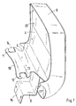
- eine schaubildliche Darstellung einer Halteplatte für einen Monitor mit Abstützkonsole, Befestigungsteilen und Abdeckschale,
- Fig. 2
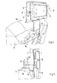
- eine schaubildliche Darstellung des montierten Monitors am Vordersitz,
- Fig. 3
- eine schaubildliche Darstellung der Halteplatte,
- Fig. 4
- eine schaubildliche Darstellung der an der Vordersitzlehne befestigten Halteplatte,
- Fig. 5
- eine schaubildliche Darstellung der an den Haltestangen der Kopfstütze befestigten Halteplatte,
- Fig. 6
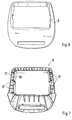
- eine Vorderansicht auf die Abdeckschale und
- Fig. 7
- eine Rückansicht auf die Abdeckschale.
- Die Befestigungsvorrichtung für einen Monitor 1 an einer Sitzlehne 2 eines Sitzes 3 eines Kraftfahrzeugs umfasst eine Halteplatte 4, welche eine Abstützkonsole 5 und ein Befestigungsteil 6 aufweist. Mit der Halteplatte 4 ist über eine Schwenklagerung S mit Schwenklagern 7, 8 ein Monitor 1 schwenkbeweglich gehalten. Eine übergesetzte Abdeckschale 9 umgibt den Monitor 9 randseitig mit samt der Halteplatte 4.
- Die Abstützkonsole 5 ist vorzugsweise einstückig mit der Halteplatte 4 ausgeführt und erstreckt sich als abgestellter Schenkel 10 etwa rechtwinkelig zur Halteplatte 4 und weist in den Seitenkanten Rastausnehmungen 11, 12 auf. Diese umgreifen rastend Haltestangen 13, 14 einer Sitzkopfstütze 25, wobei sich der Schenkel 10 auf der Sitzlehnenfläche 2a flächig abstützt.
- Das Befestigungsteil 6 besteht aus einem an der Halteplatte 4 bzw. an dem abgestellten Schenkel 10 befestigten Winkelelement und weist einen abgestellten Halteschenkel 15 auf, welcher über Befestigungsmittel mit einem Rahmenstrukturteil 16 der Sitzlehne 2 fest verbunden ist.
- Die Schwenklager 7, 8 an der Halteplatte 4 für den Monitor 1 sind zu beiden Seiten des Monitors vorgesehen und bilden eine horizontale Schwenkachse X-X. Um diese Schwenkachse X-X kann der Monitor 1 um wenige Winkelgrade beispielsweise von 5 bis 10 Grad in beiden Richtungen verschwenkt werden.
- Die Halteplatte 4 sowie der Monitor 1 sind von einer Abdeckschale 9 umgeben, die formgenau mit der Außenfläche der Rückenlehne bzw. der stirnseitigen Sitzlehnenfläche 2a in korrespondierender Anlage abschließt. Diese Abdeckschale 9 umfasst im Wesentlichen einen inneren Rahmen 20 und einen äußeren Rahmen 21 zwischen denen seitlich Dome 22 angeformt sind, die zur Befestigung mit der Halteplatte 4 dienen. Die entsprechenden Schraubmittel 23 sind in Fig. 1 näher dargestellt.
Claims (7)
- Befestigungsvorrichtung für einen Monitor an einem Fahrzeugsitz, insbesondere an einem Vordersitz eines Kraftfahrzeugs, wobei die Vorrichtung mit einer Sitzlehne verbunden ist, dadurch gekennzeichnet, dass der Monitor (1) mit einer aufrecht am Sitz (3) angeordneten Halteplatte (4) verbunden ist, die einerseits eine Abstützkonsole (5) zur Sitzlehne (2) und andererseits ein Befestigungsteil (6) umfasst, das mit einem Rahmenstrukturteil (16) der Sitzlehne (2) verbindbar ist.
- Befestigungsvorrichtung nach Anspruch 1, dadurch gekennzeichnet, dass die Abstützkonsole (5) der Halteplatte (4) aus einem abgestellten Schenkel (10) besteht, der Rastausnehmungen (11, 12) zur Umfassung von Haltestangen (13, 14) einer Sitzkopfstütze (25) aufweist und der Schenkel (10) flächig auf einer stirnseitigen Sitzlehnenfläche (2a) abstützend aufliegt.
- Befestigungsvorrichtung nach den Ansprüchen 1 oder 2, dadurch gekennzeichnet, dass das Befestigungsteil (6) aus einem Winkelelement mit einem abgestellten Halteschenkel (15) besteht, der am Rahmenstrukturteil (16) befestigt ist und der Halte-Schenkel (15) in der Höhe beabstandet zum abgestellten Schenkel (10) der Abstützkonsole (5) angeordnet ist.
- Befestigungsvorrichtung nach den Ansprüchen 1, 2 oder 3, dadurch gekennzeichnet, dass der Monitor (1) über eine Schwenklagerung (5) mit der Halteplatte (4) verbunden ist, die zu beiden Seiten des Monitors (1) vorgesehen ist und die einzelnen Schwenklager (7, 8) eine horizontale Schwenkachse (X-X) bilden.
- Befestigungsvorrichtung nach den Ansprüchen 1, 2, 3 oder 4, dadurch gekennzeichnet, dass die Halteplatte (4) mit einer den Monitor (1) umfassenden Abdeckschale (9) verbunden ist, die über Schraubmittel (23) an der Halteplatte (4) befestigbar ist.
- Befestigungsvorrichtung nach einem der vorhergehenden Ansprüche, dadurch gekennzeichnet, dass die Abdeckschale (9) einen inneren Rahmen (20) und einen äußeren Rahmen (21) umfasst, wobei zwischen den seitlichen Rahmenteilen der Rahmen (20, 21) Dome (22) für die Schraubmittel (23) vorgesehen sind.
- Befestigungsvorrichtung nach Anspruch 6, dadurch gekennzeichnet, dass der äußere und innere Rahmen (20, 21) der Abdeckschale (9) einen mit der Lehnenkontur im Bereich der stirnseitigen Sitzlehnenfläche (2a) korrespondierenden Kantenverlauf aufweist und die Abdeckschale (9) mit der Halteplatte (4) in etwa abschließt.
Applications Claiming Priority (1)
| Application Number | Priority Date | Filing Date | Title |
|---|---|---|---|
| DE102004053452A DE102004053452B3 (de) | 2004-11-05 | 2004-11-05 | Befestigungsvorrichtung für einen Monitor an einem Fahrzeugsitz |
Publications (2)
| Publication Number | Publication Date |
|---|---|
| EP1655177A1 true EP1655177A1 (de) | 2006-05-10 |
| EP1655177B1 EP1655177B1 (de) | 2007-07-25 |
Family
ID=35717659
Family Applications (1)
| Application Number | Title | Priority Date | Filing Date |
|---|---|---|---|
| EP05021550A Expired - Lifetime EP1655177B1 (de) | 2004-11-05 | 2005-10-01 | Befestigungsvorrichtung für einen Monitor an einem Fahrzeugsitz |
Country Status (4)
| Country | Link |
|---|---|
| EP (1) | EP1655177B1 (de) |
| AT (1) | ATE367951T1 (de) |
| DE (2) | DE102004053452B3 (de) |
| ES (1) | ES2287853T3 (de) |
Cited By (5)
| Publication number | Priority date | Publication date | Assignee | Title |
|---|---|---|---|---|
| WO2007075461A3 (en) * | 2005-12-22 | 2008-07-17 | Johnson Controls Tech Co | Seatback entertainment display system |
| WO2008086202A2 (en) | 2007-01-05 | 2008-07-17 | Audiovox Corporation | Rear seat entertainment system for a vehicle having an active headrest |
| EP2058169A1 (de) * | 2007-11-08 | 2009-05-13 | Ford Global Technologies, LLC | Montageanordnung |
| DE102010047442A1 (de) | 2010-10-04 | 2012-04-05 | Audi Ag | Vorrichtung zum Befestigen zumindest eines Halters für ein Funktionselement an einer Rückenlehne |
| US11225202B1 (en) | 2020-09-21 | 2022-01-18 | Ford Global Technologies, Llc | Vehicle seat display assembly |
Families Citing this family (3)
| Publication number | Priority date | Publication date | Assignee | Title |
|---|---|---|---|---|
| DE102011120876A1 (de) | 2011-12-09 | 2013-06-13 | Volkswagen Aktiengesellschaft | Haltevorrichtung für ein tragbares elektronisches Gerät mit einem Bildschirm |
| DE102013010067A1 (de) * | 2013-06-11 | 2014-12-11 | Sertan Gürbüz | Gerät für die Wiedergabe elektronischer Medien |
| DE102014009821B4 (de) | 2014-07-02 | 2017-01-12 | Robert Virant | Mehradriger elektrischer Federkontaktstift-Verbinder |
Citations (5)
| Publication number | Priority date | Publication date | Assignee | Title |
|---|---|---|---|---|
| DE19943696A1 (de) | 1999-09-07 | 2001-03-08 | Igor Zaitsev | Handliche Befestigungskonsole für schnelle und sichere Montage von mobilen Bildschirmgeräten im Fond des Autos |
| JP2002036968A (ja) * | 2000-07-25 | 2002-02-06 | Kenwood Corp | 後部座席用車載モニター |
| US6418010B1 (en) * | 2000-08-11 | 2002-07-09 | Gateway, Inc. | Convertible flat panel display hanging support |
| DE202004008205U1 (de) * | 2004-05-18 | 2004-08-26 | Techcom Carcommunikation Ag | DVD-Unterhaltungseinrichtung für ein Kraftfahrzeug |
| DE202004008944U1 (de) * | 2004-06-04 | 2004-09-09 | Techcom Carcommunikation Ag | DVD-Unterhaltungseinrichtung für ein Kraftfahrzeug |
Family Cites Families (1)
| Publication number | Priority date | Publication date | Assignee | Title |
|---|---|---|---|---|
| DE10258306B4 (de) * | 2002-12-13 | 2007-01-11 | Daimlerchrysler Ag | Fahrersitzintegrierter Monitor für Fondinsassen |
-
2004
- 2004-11-05 DE DE102004053452A patent/DE102004053452B3/de not_active Expired - Fee Related
-
2005
- 2005-10-01 DE DE502005001090T patent/DE502005001090D1/de not_active Expired - Lifetime
- 2005-10-01 EP EP05021550A patent/EP1655177B1/de not_active Expired - Lifetime
- 2005-10-01 AT AT05021550T patent/ATE367951T1/de not_active IP Right Cessation
- 2005-10-01 ES ES05021550T patent/ES2287853T3/es not_active Expired - Lifetime
Patent Citations (5)
| Publication number | Priority date | Publication date | Assignee | Title |
|---|---|---|---|---|
| DE19943696A1 (de) | 1999-09-07 | 2001-03-08 | Igor Zaitsev | Handliche Befestigungskonsole für schnelle und sichere Montage von mobilen Bildschirmgeräten im Fond des Autos |
| JP2002036968A (ja) * | 2000-07-25 | 2002-02-06 | Kenwood Corp | 後部座席用車載モニター |
| US6418010B1 (en) * | 2000-08-11 | 2002-07-09 | Gateway, Inc. | Convertible flat panel display hanging support |
| DE202004008205U1 (de) * | 2004-05-18 | 2004-08-26 | Techcom Carcommunikation Ag | DVD-Unterhaltungseinrichtung für ein Kraftfahrzeug |
| DE202004008944U1 (de) * | 2004-06-04 | 2004-09-09 | Techcom Carcommunikation Ag | DVD-Unterhaltungseinrichtung für ein Kraftfahrzeug |
Non-Patent Citations (1)
| Title |
|---|
| PATENT ABSTRACTS OF JAPAN vol. 2002, no. 06 4 June 2002 (2002-06-04) * |
Cited By (7)
| Publication number | Priority date | Publication date | Assignee | Title |
|---|---|---|---|---|
| WO2007075461A3 (en) * | 2005-12-22 | 2008-07-17 | Johnson Controls Tech Co | Seatback entertainment display system |
| WO2008086202A2 (en) | 2007-01-05 | 2008-07-17 | Audiovox Corporation | Rear seat entertainment system for a vehicle having an active headrest |
| EP2112979A4 (de) * | 2007-01-05 | 2011-03-23 | Audiovox Corp | Rücksitzunterhaltungssystem für ein fahrzeug mit aktiver kopfstütze |
| US8730413B2 (en) | 2007-01-05 | 2014-05-20 | Voxx International Corporation | Rear seat entertainment system for a vehicle having an active headrest |
| EP2058169A1 (de) * | 2007-11-08 | 2009-05-13 | Ford Global Technologies, LLC | Montageanordnung |
| DE102010047442A1 (de) | 2010-10-04 | 2012-04-05 | Audi Ag | Vorrichtung zum Befestigen zumindest eines Halters für ein Funktionselement an einer Rückenlehne |
| US11225202B1 (en) | 2020-09-21 | 2022-01-18 | Ford Global Technologies, Llc | Vehicle seat display assembly |
Also Published As
| Publication number | Publication date |
|---|---|
| ES2287853T3 (es) | 2007-12-16 |
| DE102004053452B3 (de) | 2006-08-03 |
| DE502005001090D1 (de) | 2007-09-06 |
| EP1655177B1 (de) | 2007-07-25 |
| ATE367951T1 (de) | 2007-08-15 |
Similar Documents
| Publication | Publication Date | Title |
|---|---|---|
| EP1153823B1 (de) | Fahrzeugaufbau für einen Vorderwagen eines Kraftfahrzeugs | |
| EP1892514A2 (de) | Vorrichtung zur Halterung eines Fahrroboters | |
| EP1128981A1 (de) | Fahrzeugsitz mit schnellmontageverbindung | |
| DE19613870C2 (de) | Fangvorrichtung für ein Antriebsaggregat | |
| EP1243477A2 (de) | Aufnahme- und Verbindungsvorrichtung für eine Bug/Heckschürze eines Kraftfahrzeugs | |
| EP1655177B1 (de) | Befestigungsvorrichtung für einen Monitor an einem Fahrzeugsitz | |
| DE10119114A1 (de) | Frontmodul mit Montageträger für ein Kraftfahrzeug | |
| DE102007049067B3 (de) | Fahrzeugsitz, insbesondere Kraftfahrzeugsitz | |
| DE69106076T2 (de) | Gefüge für die Herstellung von Sitzreihen und mit diesem Gefüge hergestellter Sitz. | |
| DE102013218096A1 (de) | Lehnensitzrahmen für einen Sitz, insbesondere einen Fahrzeugsitz und Fahrzeugsitz | |
| DE19746463C1 (de) | Kraftfahrzeugrückenlehne mit Lehnenrahmen und Kopfstütze | |
| DE4333463A1 (de) | Wohnwagen mit einer Befestigungsvorrichtung für Sicherheitsgurte | |
| DE102012007978A1 (de) | Fahrzeugsitz für ein Kraftfahrzeug | |
| DE10031157C1 (de) | Aufnahmevorrichtung für Pedale eines Kraftfahrzeugs | |
| DE8315396U1 (de) | Kuehlerbefestigung fuer kraftfahrzeuge | |
| DE9308942U1 (de) | Sitzbank für Kraftfahrzeuge, insbesondere Wohnmobile | |
| DE102004004376B3 (de) | Befestigungsvorrichtung für einen Kindersitz | |
| DE10149003A1 (de) | Vorrichtung zum Fixieren von Karosserieteilen | |
| DE19906669C2 (de) | Vorrichtung zur Befestigung eines Fahrzeugsitzes | |
| EP1775173A2 (de) | Vorrichtung zur Befestigung eines Sensors | |
| DE102023117500B4 (de) | Fahrrad mit einem Radschützer sowie Radschützer | |
| DE4028254C1 (en) | Adjustable seat in vehicle - uses flat plates with flexures securing back and seat cushions | |
| DE8634436U1 (de) | Befestigungsvorrichtung | |
| WO2017216138A1 (de) | Verfahren zur herstellung einer lehnenstruktur für einen fahrzeugsitz, sowie lehnenstruktur für einen fahrzeugsitz | |
| DE102012012490B4 (de) | Befestigungsanordnung |
Legal Events
| Date | Code | Title | Description |
|---|---|---|---|
| PUAI | Public reference made under article 153(3) epc to a published international application that has entered the european phase |
Free format text: ORIGINAL CODE: 0009012 |
|
| AK | Designated contracting states |
Kind code of ref document: A1 Designated state(s): AT BE BG CH CY CZ DE DK EE ES FI FR GB GR HU IE IS IT LI LT LU LV MC NL PL PT RO SE SI SK TR |
|
| AX | Request for extension of the european patent |
Extension state: AL BA HR MK YU |
|
| 17P | Request for examination filed |
Effective date: 20061110 |
|
| AKX | Designation fees paid |
Designated state(s): AT BE BG CH CY CZ DE DK EE ES FI FR GB GR HU IE IS IT LI LT LU LV MC NL PL PT RO SE SI SK TR |
|
| GRAP | Despatch of communication of intention to grant a patent |
Free format text: ORIGINAL CODE: EPIDOSNIGR1 |
|
| GRAS | Grant fee paid |
Free format text: ORIGINAL CODE: EPIDOSNIGR3 |
|
| GRAA | (expected) grant |
Free format text: ORIGINAL CODE: 0009210 |
|
| AK | Designated contracting states |
Kind code of ref document: B1 Designated state(s): AT BE BG CH CY CZ DE DK EE ES FI FR GB GR HU IE IS IT LI LT LU LV MC NL PL PT RO SE SI SK TR |
|
| REG | Reference to a national code |
Ref country code: GB Ref legal event code: FG4D Free format text: NOT ENGLISH |
|
| REG | Reference to a national code |
Ref country code: CH Ref legal event code: EP |
|
| REG | Reference to a national code |
Ref country code: IE Ref legal event code: FG4D Free format text: LANGUAGE OF EP DOCUMENT: GERMAN |
|
| REF | Corresponds to: |
Ref document number: 502005001090 Country of ref document: DE Date of ref document: 20070906 Kind code of ref document: P |
|
| GBT | Gb: translation of ep patent filed (gb section 77(6)(a)/1977) |
Effective date: 20070917 |
|
| REG | Reference to a national code |
Ref country code: SE Ref legal event code: TRGR |
|
| REG | Reference to a national code |
Ref country code: ES Ref legal event code: FG2A Ref document number: 2287853 Country of ref document: ES Kind code of ref document: T3 |
|
| ET | Fr: translation filed | ||
| PG25 | Lapsed in a contracting state [announced via postgrant information from national office to epo] |
Ref country code: FI Free format text: LAPSE BECAUSE OF FAILURE TO SUBMIT A TRANSLATION OF THE DESCRIPTION OR TO PAY THE FEE WITHIN THE PRESCRIBED TIME-LIMIT Effective date: 20070725 Ref country code: BG Free format text: LAPSE BECAUSE OF FAILURE TO SUBMIT A TRANSLATION OF THE DESCRIPTION OR TO PAY THE FEE WITHIN THE PRESCRIBED TIME-LIMIT Effective date: 20071025 Ref country code: LT Free format text: LAPSE BECAUSE OF FAILURE TO SUBMIT A TRANSLATION OF THE DESCRIPTION OR TO PAY THE FEE WITHIN THE PRESCRIBED TIME-LIMIT Effective date: 20070725 Ref country code: PT Free format text: LAPSE BECAUSE OF FAILURE TO SUBMIT A TRANSLATION OF THE DESCRIPTION OR TO PAY THE FEE WITHIN THE PRESCRIBED TIME-LIMIT Effective date: 20071226 Ref country code: IS Free format text: LAPSE BECAUSE OF FAILURE TO SUBMIT A TRANSLATION OF THE DESCRIPTION OR TO PAY THE FEE WITHIN THE PRESCRIBED TIME-LIMIT Effective date: 20071125 |
|
| PGFP | Annual fee paid to national office [announced via postgrant information from national office to epo] |
Ref country code: ES Payment date: 20071030 Year of fee payment: 3 |
|
| PG25 | Lapsed in a contracting state [announced via postgrant information from national office to epo] |
Ref country code: PL Free format text: LAPSE BECAUSE OF FAILURE TO SUBMIT A TRANSLATION OF THE DESCRIPTION OR TO PAY THE FEE WITHIN THE PRESCRIBED TIME-LIMIT Effective date: 20070725 |
|
| REG | Reference to a national code |
Ref country code: IE Ref legal event code: FD4D |
|
| PG25 | Lapsed in a contracting state [announced via postgrant information from national office to epo] |
Ref country code: LV Free format text: LAPSE BECAUSE OF FAILURE TO SUBMIT A TRANSLATION OF THE DESCRIPTION OR TO PAY THE FEE WITHIN THE PRESCRIBED TIME-LIMIT Effective date: 20070725 |
|
| PGFP | Annual fee paid to national office [announced via postgrant information from national office to epo] |
Ref country code: SE Payment date: 20071012 Year of fee payment: 3 |
|
| BERE | Be: lapsed |
Owner name: DR. ING. H.C. F. PORSCHE A.G. Effective date: 20071031 |
|
| PG25 | Lapsed in a contracting state [announced via postgrant information from national office to epo] |
Ref country code: DK Free format text: LAPSE BECAUSE OF FAILURE TO SUBMIT A TRANSLATION OF THE DESCRIPTION OR TO PAY THE FEE WITHIN THE PRESCRIBED TIME-LIMIT Effective date: 20070725 Ref country code: GR Free format text: LAPSE BECAUSE OF FAILURE TO SUBMIT A TRANSLATION OF THE DESCRIPTION OR TO PAY THE FEE WITHIN THE PRESCRIBED TIME-LIMIT Effective date: 20071026 |
|
| PG25 | Lapsed in a contracting state [announced via postgrant information from national office to epo] |
Ref country code: IE Free format text: LAPSE BECAUSE OF FAILURE TO SUBMIT A TRANSLATION OF THE DESCRIPTION OR TO PAY THE FEE WITHIN THE PRESCRIBED TIME-LIMIT Effective date: 20070725 Ref country code: MC Free format text: LAPSE BECAUSE OF NON-PAYMENT OF DUE FEES Effective date: 20071031 Ref country code: SK Free format text: LAPSE BECAUSE OF FAILURE TO SUBMIT A TRANSLATION OF THE DESCRIPTION OR TO PAY THE FEE WITHIN THE PRESCRIBED TIME-LIMIT Effective date: 20070725 Ref country code: CZ Free format text: LAPSE BECAUSE OF FAILURE TO SUBMIT A TRANSLATION OF THE DESCRIPTION OR TO PAY THE FEE WITHIN THE PRESCRIBED TIME-LIMIT Effective date: 20070725 |
|
| PLBE | No opposition filed within time limit |
Free format text: ORIGINAL CODE: 0009261 |
|
| STAA | Information on the status of an ep patent application or granted ep patent |
Free format text: STATUS: NO OPPOSITION FILED WITHIN TIME LIMIT |
|
| PG25 | Lapsed in a contracting state [announced via postgrant information from national office to epo] |
Ref country code: RO Free format text: LAPSE BECAUSE OF FAILURE TO SUBMIT A TRANSLATION OF THE DESCRIPTION OR TO PAY THE FEE WITHIN THE PRESCRIBED TIME-LIMIT Effective date: 20070725 |
|
| 26N | No opposition filed |
Effective date: 20080428 |
|
| PG25 | Lapsed in a contracting state [announced via postgrant information from national office to epo] |
Ref country code: BE Free format text: LAPSE BECAUSE OF NON-PAYMENT OF DUE FEES Effective date: 20071031 |
|
| PGFP | Annual fee paid to national office [announced via postgrant information from national office to epo] |
Ref country code: NL Payment date: 20081015 Year of fee payment: 4 |
|
| PG25 | Lapsed in a contracting state [announced via postgrant information from national office to epo] |
Ref country code: EE Free format text: LAPSE BECAUSE OF FAILURE TO SUBMIT A TRANSLATION OF THE DESCRIPTION OR TO PAY THE FEE WITHIN THE PRESCRIBED TIME-LIMIT Effective date: 20070725 |
|
| PG25 | Lapsed in a contracting state [announced via postgrant information from national office to epo] |
Ref country code: AT Free format text: LAPSE BECAUSE OF NON-PAYMENT OF DUE FEES Effective date: 20071001 |
|
| EUG | Se: european patent has lapsed | ||
| PG25 | Lapsed in a contracting state [announced via postgrant information from national office to epo] |
Ref country code: SI Free format text: LAPSE BECAUSE OF FAILURE TO SUBMIT A TRANSLATION OF THE DESCRIPTION OR TO PAY THE FEE WITHIN THE PRESCRIBED TIME-LIMIT Effective date: 20070725 |
|
| REG | Reference to a national code |
Ref country code: FR Ref legal event code: TP |
|
| PG25 | Lapsed in a contracting state [announced via postgrant information from national office to epo] |
Ref country code: CY Free format text: LAPSE BECAUSE OF FAILURE TO SUBMIT A TRANSLATION OF THE DESCRIPTION OR TO PAY THE FEE WITHIN THE PRESCRIBED TIME-LIMIT Effective date: 20070725 |
|
| PG25 | Lapsed in a contracting state [announced via postgrant information from national office to epo] |
Ref country code: LU Free format text: LAPSE BECAUSE OF NON-PAYMENT OF DUE FEES Effective date: 20071001 |
|
| PG25 | Lapsed in a contracting state [announced via postgrant information from national office to epo] |
Ref country code: HU Free format text: LAPSE BECAUSE OF FAILURE TO SUBMIT A TRANSLATION OF THE DESCRIPTION OR TO PAY THE FEE WITHIN THE PRESCRIBED TIME-LIMIT Effective date: 20080126 Ref country code: TR Free format text: LAPSE BECAUSE OF FAILURE TO SUBMIT A TRANSLATION OF THE DESCRIPTION OR TO PAY THE FEE WITHIN THE PRESCRIBED TIME-LIMIT Effective date: 20070725 |
|
| REG | Reference to a national code |
Ref country code: FR Ref legal event code: CD |
|
| REG | Reference to a national code |
Ref country code: ES Ref legal event code: FD2A Effective date: 20081002 |
|
| PG25 | Lapsed in a contracting state [announced via postgrant information from national office to epo] |
Ref country code: ES Free format text: LAPSE BECAUSE OF NON-PAYMENT OF DUE FEES Effective date: 20081002 |
|
| REG | Reference to a national code |
Ref country code: NL Ref legal event code: V1 Effective date: 20100501 |
|
| REG | Reference to a national code |
Ref country code: CH Ref legal event code: PL |
|
| PG25 | Lapsed in a contracting state [announced via postgrant information from national office to epo] |
Ref country code: SE Free format text: LAPSE BECAUSE OF NON-PAYMENT OF DUE FEES Effective date: 20081002 Ref country code: NL Free format text: LAPSE BECAUSE OF NON-PAYMENT OF DUE FEES Effective date: 20100501 |
|
| PG25 | Lapsed in a contracting state [announced via postgrant information from national office to epo] |
Ref country code: GB Free format text: LAPSE BECAUSE OF NON-PAYMENT OF DUE FEES Effective date: 20070725 |
|
| PG25 | Lapsed in a contracting state [announced via postgrant information from national office to epo] |
Ref country code: CH Free format text: LAPSE BECAUSE OF NON-PAYMENT OF DUE FEES Effective date: 20091031 Ref country code: LI Free format text: LAPSE BECAUSE OF NON-PAYMENT OF DUE FEES Effective date: 20091031 |
|
| PGFP | Annual fee paid to national office [announced via postgrant information from national office to epo] |
Ref country code: FR Payment date: 20101104 Year of fee payment: 6 |
|
| REG | Reference to a national code |
Ref country code: FR Ref legal event code: TP |
|
| PGFP | Annual fee paid to national office [announced via postgrant information from national office to epo] |
Ref country code: IT Payment date: 20081031 Year of fee payment: 4 |
|
| REG | Reference to a national code |
Ref country code: FR Ref legal event code: ST Effective date: 20120629 |
|
| PG25 | Lapsed in a contracting state [announced via postgrant information from national office to epo] |
Ref country code: FR Free format text: LAPSE BECAUSE OF NON-PAYMENT OF DUE FEES Effective date: 20111102 |
|
| PGFP | Annual fee paid to national office [announced via postgrant information from national office to epo] |
Ref country code: DE Payment date: 20181016 Year of fee payment: 14 |
|
| REG | Reference to a national code |
Ref country code: DE Ref legal event code: R119 Ref document number: 502005001090 Country of ref document: DE |
|
| PG25 | Lapsed in a contracting state [announced via postgrant information from national office to epo] |
Ref country code: DE Free format text: LAPSE BECAUSE OF NON-PAYMENT OF DUE FEES Effective date: 20200501 |