EP1654950A1 - Bracelet fastener - Google Patents
Bracelet fastener Download PDFInfo
- Publication number
- EP1654950A1 EP1654950A1 EP04405673A EP04405673A EP1654950A1 EP 1654950 A1 EP1654950 A1 EP 1654950A1 EP 04405673 A EP04405673 A EP 04405673A EP 04405673 A EP04405673 A EP 04405673A EP 1654950 A1 EP1654950 A1 EP 1654950A1
- Authority
- EP
- European Patent Office
- Prior art keywords
- lever
- branches
- hook
- cover
- axis
- Prior art date
- Legal status (The legal status is an assumption and is not a legal conclusion. Google has not performed a legal analysis and makes no representation as to the accuracy of the status listed.)
- Granted
Links
- 230000000694 effects Effects 0.000 claims 1
- 238000007373 indentation Methods 0.000 claims 1
- 230000008878 coupling Effects 0.000 abstract 1
- 238000010168 coupling process Methods 0.000 abstract 1
- 238000005859 coupling reaction Methods 0.000 abstract 1
- 230000008901 benefit Effects 0.000 description 3
- 230000007547 defect Effects 0.000 description 2
- 229910000831 Steel Inorganic materials 0.000 description 1
- 238000005452 bending Methods 0.000 description 1
- 230000000903 blocking effect Effects 0.000 description 1
- 230000000295 complement effect Effects 0.000 description 1
- 230000001419 dependent effect Effects 0.000 description 1
- PCHJSUWPFVWCPO-UHFFFAOYSA-N gold Chemical compound [Au] PCHJSUWPFVWCPO-UHFFFAOYSA-N 0.000 description 1
- 239000010931 gold Substances 0.000 description 1
- 229910052737 gold Inorganic materials 0.000 description 1
- 230000037431 insertion Effects 0.000 description 1
- 238000003780 insertion Methods 0.000 description 1
- 239000000463 material Substances 0.000 description 1
- 239000010959 steel Substances 0.000 description 1
Images


Classifications
-
- A—HUMAN NECESSITIES
- A44—HABERDASHERY; JEWELLERY
- A44C—PERSONAL ADORNMENTS, e.g. JEWELLERY; COINS
- A44C5/00—Bracelets; Wrist-watch straps; Fastenings for bracelets or wrist-watch straps
- A44C5/18—Fasteners for straps, chains or the like
- A44C5/20—Fasteners for straps, chains or the like for open straps, chains or the like
- A44C5/2042—Fasteners provided with a turnable clamping lever
-
- A—HUMAN NECESSITIES
- A44—HABERDASHERY; JEWELLERY
- A44C—PERSONAL ADORNMENTS, e.g. JEWELLERY; COINS
- A44C5/00—Bracelets; Wrist-watch straps; Fastenings for bracelets or wrist-watch straps
- A44C5/18—Fasteners for straps, chains or the like
- A44C5/22—Fasteners for straps, chains or the like for closed straps
- A44C5/24—Fasteners for straps, chains or the like for closed straps with folding devices
-
- Y—GENERAL TAGGING OF NEW TECHNOLOGICAL DEVELOPMENTS; GENERAL TAGGING OF CROSS-SECTIONAL TECHNOLOGIES SPANNING OVER SEVERAL SECTIONS OF THE IPC; TECHNICAL SUBJECTS COVERED BY FORMER USPC CROSS-REFERENCE ART COLLECTIONS [XRACs] AND DIGESTS
- Y10—TECHNICAL SUBJECTS COVERED BY FORMER USPC
- Y10T—TECHNICAL SUBJECTS COVERED BY FORMER US CLASSIFICATION
- Y10T24/00—Buckles, buttons, clasps, etc.
- Y10T24/21—Strap tighteners
- Y10T24/2143—Strap-attached folding lever
- Y10T24/2155—Jewelry-watch straps
-
- Y—GENERAL TAGGING OF NEW TECHNOLOGICAL DEVELOPMENTS; GENERAL TAGGING OF CROSS-SECTIONAL TECHNOLOGIES SPANNING OVER SEVERAL SECTIONS OF THE IPC; TECHNICAL SUBJECTS COVERED BY FORMER USPC CROSS-REFERENCE ART COLLECTIONS [XRACs] AND DIGESTS
- Y10—TECHNICAL SUBJECTS COVERED BY FORMER USPC
- Y10T—TECHNICAL SUBJECTS COVERED BY FORMER US CLASSIFICATION
- Y10T24/00—Buckles, buttons, clasps, etc.
- Y10T24/47—Strap-end-attaching devices
- Y10T24/4736—Buckle connected
-
- Y—GENERAL TAGGING OF NEW TECHNOLOGICAL DEVELOPMENTS; GENERAL TAGGING OF CROSS-SECTIONAL TECHNOLOGIES SPANNING OVER SEVERAL SECTIONS OF THE IPC; TECHNICAL SUBJECTS COVERED BY FORMER USPC CROSS-REFERENCE ART COLLECTIONS [XRACs] AND DIGESTS
- Y10—TECHNICAL SUBJECTS COVERED BY FORMER USPC
- Y10T—TECHNICAL SUBJECTS COVERED BY FORMER US CLASSIFICATION
- Y10T24/00—Buckles, buttons, clasps, etc.
- Y10T24/47—Strap-end-attaching devices
- Y10T24/4745—End clasp
-
- Y—GENERAL TAGGING OF NEW TECHNOLOGICAL DEVELOPMENTS; GENERAL TAGGING OF CROSS-SECTIONAL TECHNOLOGIES SPANNING OVER SEVERAL SECTIONS OF THE IPC; TECHNICAL SUBJECTS COVERED BY FORMER USPC CROSS-REFERENCE ART COLLECTIONS [XRACs] AND DIGESTS
- Y10—TECHNICAL SUBJECTS COVERED BY FORMER USPC
- Y10T—TECHNICAL SUBJECTS COVERED BY FORMER US CLASSIFICATION
- Y10T24/00—Buckles, buttons, clasps, etc.
- Y10T24/47—Strap-end-attaching devices
- Y10T24/4782—Watch strap
Definitions
- the present invention relates to a bracelet clasp having at least two arms articulated to one another by one of their respective ends, a locking device for holding the free ends of these two branches in the folded position and means for link between their free ends and the respective ends of a bracelet.
- This type of clasp is well known particularly in the field of clasps for watch straps.
- the folding branches of the clasp can increase very significantly the length of the bracelet in the open position of the clasp, which allows to pass the wristwatch around the hand without the need to separate the bracelet.
- the object of the present invention is to overcome, at least in part, the aforementioned drawbacks.
- this invention relates to a bracelet clasp according to the definition given by claim 1.
- the lever of the clasp according to the invention acts well on the elastic return means as a lever, which makes it allows to obtain a reduction of the force exerted on it to bend the elastic return means. With this reduction of the manual force exerted on the lever to open the clasp, it can increase the strength of the elastic return means and thus increase the force exerted on the locking hook. This force continues to be exercised in the closed position, keeping the branches tight against each other, thus catching up the play between the branches of the clasp.
- the clasp illustrated in Figures 1 to 4 comprises two branches 1, 2 articulated by one of their ends around an axis 3 ( Figure 4).
- the free end of the branch 1 has a fastening element 4 which, in this embodiment, is in the form of a transverse element, parallel to the hinge axis 3.
- This fastening element 4 is located in a portion 1a of the free end of the branch 1, curved outwards.
- a space is provided between this fastening element 4 and the bottom of this curved portion la to allow insertion of a fastening member between the fastening element 4 and the bottom of the curved portion 1a as will be explained. thereafter.
- This same free end is still integral with two axes of joints 5, 6, parallel to the hinge axis 3 of the branches 1, 2.
- One of these axes serves to the articulation of a locking cover 7, while the other serves to articulate an end of one of the strands of the bracelet (not shown).
- the free end of the branch 2 is thicker than the rest of this branch, to receive a hinge pin 8. This extra thickness is obtained by bending the face of this branch 2 facing the branch 1, so that closed position, this curved face of the branch 2 substantially matches the shape of the beginning of the curved portion la because it is shorter than the branch 1, as can be seen in Figure 3.
- a connecting member 9 is articulated to the free end of the branch 2 about the hinge axis 8 to allow it to free articulation of at least 180 ° to facilitate the deployment of this branch 2 for the free passage of the hand in the open position.
- This connecting member 9 comprises two other axes 10 and 11.
- the axis 10 serves for the articulation of a locking lever 12 and the axis 11 serves to connect a cover 13.
- This has two side walls parallel in which is formed a plurality of pairs of positioning elements formed of circular impressions 14 on their opposite internal faces, for fixing a bar (not shown) in one or the other pair of fingerprints, following the desired length for the bracelet.
- the connecting member 9 has a surface 9a adjacent to the inner face of the upper wall of the cover 13. This surface 9a serves to block the pivoting of the cover 13 about the axis 11.
- a spring 15 bears on a rod 16 secured to the connecting member 9, passes around the hinge axis 10 between this connecting member 9 and the locking lever 12 and the other end of this spring 15 bears against the inner face of the upper wall of the locking lever 12.
- this spring creates a torque on the locking lever 12 which tends to do so turn counterclockwise in Figures 1-4.
- two springs 15 are arranged along the pivot axis 10, on either side of the connecting member 9 which is at the center of the pivot axis 10.
- the locking lever 12 carries a locking hook 17 shaped to be able to engage between the locking element 4 integral with the free end of the branch 1 and the bottom of the curved portion 1a of this branch 1, in which position it is held by the torque applied to it by the springs 15.
- the rear end of the locking lever 12, situated under the front end of the cover 13 transmits a torque to the latter via the the link member 9.
- This pair makes it possible to keep the lid 13 very close, or even to apply it against the bracelet strand, the end of which is fixed in one of the pairs of positioning elements formed of impressions 14 and prevents it from departing. This avoids the cover 13 the risk of clinging during movements made by the person wearing a bracelet with the clasp according to the invention.
- a clasp whose cover can move freely from the bracelet due to its play, affects the appearance of this clasp and is a factor of depreciation.
- the locking cover 7 is provided as additional security. It is intended to cover the locking lever 12 by tilting, once the locking hook 17 has been hooked to the locking element 4. This locking cover 7 can be held in the folded position by two fingerprints 7a provided on the internal faces of its side walls which can engage on the opposite ends of the pivot axis 10 of the lever 12 which then project from the side faces of the lever 12 and can retract against the pressure a coil spring disposed in the pivot axis 10, like a well-known piston bar for attaching a bracelet to the horns of a wristwatch box.
- the second embodiment differs essentially from the first embodiment because of the absence of the second locking cover 7. Another difference lies in the fact that an axis 20 serves for the articulation of the lever 22 on the connecting member 19, and to connect the lid 23 to this connecting member 19.
- the lever 22 is covered with a cover 28 which increases the length of the lever arm.
- This lever 22 carries a hook 27 intended to hook to the locking element 4 of the branch 1 exactly as in the first embodiment.
- the third embodiment illustrated in FIG. 5 is intended to integrate the clasp into a bracelet to articulated links formed of at least three longitudinal rows of links, in which the links of a row are offset longitudinally by half a step from those of the adjacent row, the pitch corresponding to the longitudinal distance between two adjacent links of the same row.
- the free end of the branch 1 is integral with at least one link 29, several similar links can be aligned transversely to the link 29 according to the number of rows of links that includes the bracelet to be connected to the clasp.
- This or these links 29 comprise a transverse locking rod 34 and a screw shaft 35 to make the connection with the bracelet (not shown).
- the connecting member 30 which is articulated about an articulation axis 31, at the free end of the branch 2, comprises a second hinge axis 32 which is articulated the locking lever 33 which is present in the external form of a link 33a which is fixed a gripping element 33b.
- the lower face front portion of the locking lever 33 is recessed to form a hook 33c.
- a housing 33d is provided in the rear portion of the underside of the link lever 33a for housing a cylinder 36 which encloses a coil spring and a piston 37, pressed outwardly by the coil spring.
- This piston 37 is limited by its rear portion of larger diameter, so that it stops at the end of the stroke, against the front face of the cylinder 36 through an opening which passes the visible outer portion, of smaller diameter of the piston 37.
- the outer end of the piston 37 rests against the upper face of the branch 2 of the clasp and applies to the lever 33 a torque around the axis of articulation 32 years the opposite direction to that needles of the watch.
- the hinge axis 32 of the connecting member is also used for the articulation of two connecting links 38, located transversely on either side of the locking lever 33 in the form of a link 33a.
- These connecting links 38 comprise a hinge pin 39 to allow the attachment of an end of a strand of the bracelet (not shown).
- the hooking of the locking hook 33c on the locking rod 34 is effected by raising the lever 33 or by rotating it clockwise about the hinge axis 32 against the force of the return spring exerted via the piston 37.
Abstract
Description
La présente invention se rapporte à un fermoir de bracelet comportant au moins deux branches articulées l'une à l'autre par une de leurs extrémités respectives, un dispositif de verrouillage pour maintenir les extrémités libres de ces deux branches en position repliée et des moyens de liaison entre leurs extrémités libres et les extrémités respectives d'un bracelet.The present invention relates to a bracelet clasp having at least two arms articulated to one another by one of their respective ends, a locking device for holding the free ends of these two branches in the folded position and means for link between their free ends and the respective ends of a bracelet.
Ce type de fermoir est bien connu en particulier dans le domaine des fermoirs pour bracelets de montres. Les branches dépliantes du fermoir permettent d'augmenter très sensiblement la longueur du bracelet en position d'ouverture du fermoir, ce qui permet de faire passer la montre-bracelet autour de la main sans avoir besoin de séparer le bracelet.This type of clasp is well known particularly in the field of clasps for watch straps. The folding branches of the clasp can increase very significantly the length of the bracelet in the open position of the clasp, which allows to pass the wristwatch around the hand without the need to separate the bracelet.
Il existe un grand nombre de systèmes d'accrochage ou de verrouillage pour ce type de fermoir. La plupart d'entre eux utilisent l'élasticité des branches dépliantes du fermoir. Les propriétés élastiques de tels fermoirs sont donc tributaires du matériau et des dimensions des branches du fermoir. Un même fermoir n'aura donc pas les mêmes caractéristiques si il est en acier ou en or par exemple, si les lames sont usinées dans la masse ou si elles sont en tôle emboutie.There is a large number of locking or locking systems for this type of clasp. Most of them use the elasticity of the folding branches of the clasp. The elastic properties of such clasps are therefore dependent on the material and the dimensions of the branches of the clasp. The same clasp will not have the same characteristics if it is steel or gold, for example, if the blades are machined in the mass or if they are stamped sheet.
On a déjà proposé dans le EP 1 279 349 un fermoir à branches dépliantes comprenant un ou deux leviers articulés autour d'axes perpendiculaire à une des branches du bracelet et rappelés en position de verrouillage par un ressort disposé transversalement aux lames du fermoir, de sorte que ces leviers sont accessibles sur les deux faces latérales opposées du fermoir sur lesquelles ils font saillie. Ces leviers présentent chacun un rebord interne qui s'étend dans un plan perpendiculaire aux axes de pivotement respectifs des leviers et qui sont destinés à s'engager sur des rebords complémentaires d'un organe de verrouillage solidaire d'une extrémité d'une autre branche du fermoir. En écartant les rebords des leviers par des pressions exercées sur eux à l'encontre de la force exercée par le ressort, l'organe de verrouillage peut pénétrer entre les leviers et est emprisonné lorsqu'on relâche la pression sur les leviers qui sont ramenés dans leur position de verrouillage par la pression du ressort.It has already been proposed in
Si cette solution permet de rendre le verrouillage indépendant des propriétés élastiques des lames ou branches du fermoir, elle présente un certain nombre de défauts. L'un de ceux-ci est relatif à la sécurité. L'actionnement des leviers pour commander l'ouverture du fermoir résulte d'une simple pression sur des poussoirs qui font saillie latéralement du fermoir. De ce fait l'ouverture du fermoir peut être accidentelle ou involontaire suite à une pression machinale sur les poussoirs. Ce risque est bien évidemment inadmissible, en particulier pour une montre de prix.If this solution makes the locking independent of the elastic properties of the blades or branches of the clasp, it has a number of defects. One of these is related to security. The operation of the levers to control the opening of the clasp results from a simple pressure on pushers that project laterally from the clasp. Therefore the opening of the clasp can be accidental or involuntary following mechanical pressure on the pushers. This risk is obviously inadmissible, especially for a price watch.
On a proposé de remédier à cet inconvénient dans le EP 1 374 716, dans lequel le dispositif d'accrochage des deux branches du bracelet est associé à un système de verrouillage qui comporte un organe de blocage du poussoir empêchant son actionnement intempestif.It has been proposed to overcome this drawback in
Un autre inconvénient que présentent les deux dispositifs susmentionnés vient du fait que la force que le ressort de rappel exerce sur les leviers ne s'exerce pas sur les branches du fermoir, en sorte qu'il peut subsister un jeu entre celles-ci lorsqu'elles sont en position de fermeture, ce qui est perçu comme un défaut par le porteur de la montre-bracelet et n'est donc pas acceptable pour un produit de qualité.Another disadvantage presented by the two aforementioned devices comes from the fact that the force that the return spring exerts on the levers is not exerted on the branches of the clasp, so that there can remain a clearance between them when they are in the closed position, which is perceived as a defect by the wearer of the wristwatch and is therefore not acceptable for a quality product.
Le but de la présente invention est de remédier, au moins en partie, aux inconvénients susmentionnés.The object of the present invention is to overcome, at least in part, the aforementioned drawbacks.
A cet effet, cette invention a pour objet un fermoir de bracelet conforme à la définition donnée par la revendication 1.To this end, this invention relates to a bracelet clasp according to the definition given by
Contrairement à la solution susmentionnée dans laquelle on a de simples poussoirs sur lesquels la force du ressort de rappel agit directement, on pourra constater que le levier du fermoir selon l'invention agit bien sur les moyens de rappel élastiques comme un levier, ce qui lui permet d'obtenir une démultiplication de la force exercée sur lui pour faire fléchir les moyens de rappel élastique. Grâce à cette démultiplication de la force manuelle exercée sur le levier pour ouvrir le fermoir, on peut augmenter la force des moyens de rappel élastique et donc augmenter la force qui s'exerce sur le crochet de verrouillage. Cette force continue de s'exercer en position de fermeture, maintenant les branches serrées l'une contre l'autre, rattrapant ainsi les jeux entre les branches du fermoir.Unlike the aforementioned solution in which there are simple pushers on which the force of the return spring acts directly, it can be seen that the lever of the clasp according to the invention acts well on the elastic return means as a lever, which makes it allows to obtain a reduction of the force exerted on it to bend the elastic return means. With this reduction of the manual force exerted on the lever to open the clasp, it can increase the strength of the elastic return means and thus increase the force exerted on the locking hook. This force continues to be exercised in the closed position, keeping the branches tight against each other, thus catching up the play between the branches of the clasp.
Il existe plusieurs autres avantages que l'on découvrira à la lecture de la description qui suit faite à l'aide des dessins annexés qui illustrent, schématiquement et à titre d'exemple, trois formes d'exécution du fermoir objet de la présente invention.
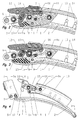
- La figure 1 est une vue éclatée d'une première forme d'exécution;
- la figure 2 est une première vue en coupe longitudinale selon un premier plan de coupe, en position fermée d'une première forme d'exécution;
- la figure 3 est une seconde vue en coupe longitudinale selon un second plan de coupe, en position fermée de cette même forme d'exécution;
- la figure 4 est une vue en coupe longitudinale du fermoir selon cette forme d'exécution, en position ouverte;
- la figure 5 est une vue en coupe d'une deuxième forme d'exécution, en position ouverte du fermoir;
- la figure 6 est une vue en coupe longitudinale d'une troisième forme d'exécution.
- Figure 1 is an exploded view of a first embodiment;
- Figure 2 is a first longitudinal sectional view along a first section plane, in the closed position of a first embodiment;
- Figure 3 is a second longitudinal sectional view along a second section plane, in the closed position of the same embodiment;
- Figure 4 is a longitudinal sectional view of the clasp according to this embodiment, in the open position;
- Figure 5 is a sectional view of a second embodiment, in the open position of the clasp;
- Figure 6 is a longitudinal sectional view of a third embodiment.
Le fermoir illustré par les figures 1 à 4 comporte deux branches 1, 2 articulées par une de leurs extrémités autour d'un axe 3 (figure 4). L'extrémité libre de la branche 1 présente un élément d'accrochage 4 qui, dans cette forme d'exécution, se présente sous la forme d'un élément transversal, parallèle à l'axe d'articulation 3. Cet élément d'accrochage 4 se situe dans une partie 1a de l'extrémité libre de la branche 1, incurvée vers l'extérieur. Un espace est ménagé entre cet élément d'accrochage 4 et le fond de cette partie incurvée la pour permettre d'insérer un organe d'accrochage entre l'élément d'accrochage 4 et le fond de la partie incurvée 1a comme on l'expliquera par la suite. Cette même extrémité libre est encore solidaire de deux axes d'articulations 5, 6, parallèles à l'axe d'articulation 3 des branches 1, 2. L'un 5 de ces axes sert à l'articulation d'un couvercle de verrouillage 7, tandis que l'autre sert à l'articulation d'une extrémité d'un des brins du bracelet (non représenté).The clasp illustrated in Figures 1 to 4 comprises two
L'extrémité libre de la branche 2 est plus épaisse que le reste de cette branche, pour recevoir un axe d'articulation 8. Cette surépaisseur est obtenue en incurvant la face de cette branche 2 tournée vers la branche 1, en sorte qu'en position fermée, cette face incurvée de la branche 2 épouse sensiblement la forme du début de la partie incurvée la du fait qu'elle est plus courte que la branche 1, comme on peut le constater sur la figure 3.The free end of the
Un organe de liaison 9 est articulé à l'extrémité libre de la branche 2 autour de l'axe d'articulation 8 pour lui permettre une libre articulation d'au moins 180° afin de faciliter le déploiement de cette branche 2 pour le libre passage de la main en position d'ouverture. Cet organe de liaison 9 comporte deux autres axes 10 et 11. L'axe 10 sert à l'articulation d'un levier de verrouillage 12 et l'axe 11 sert à relier d'un couvercle 13. Celui-ci présente deux parois latérales parallèles dans lesquelles est ménagée une pluralité de paires d'éléments de positionnement formés d'empreintes circulaires 14 sur leurs faces internes opposées, pour la fixation d'une barrette (non représentée) dans l'une ou l'autre paire d'empreintes, suivant la longueur désirée pour le bracelet.A connecting
L'organe de liaison 9 présente une surface 9a adjacente à la face interne de la paroi supérieure du couvercle 13. Cette surface 9a sert à bloquer le pivotement du couvercle 13 autour de l'axe 11. L'extrémité de ce couvercle 13, située du côté de l'extrémité libre de la branche 2, recouvre l'extrémité arrière du levier de verrouillage 12.The connecting
Comme on le voit en particulier sur la figure 3, une extrémité d'un ressort 15 prend appui sur une tige 16 solidaire de l'organe de liaison 9, passe autour de l'axe d'articulation 10 entre cet organe de liaison 9 et le levier de verrouillage 12 et l'autre extrémité de ce ressort 15 prend appui contre la face interne de la paroi supérieure du levier de verrouillage 12. De ce fait, ce ressort crée un couple sur le levier de verrouillage 12 qui tend à le faire tourner dans le sens inverse de celui des aiguilles d'une montre sur les figures 1-4. En réalité, de préférence, deux ressorts 15 sont disposés le long de l'axe de pivotement 10, de part et d'autre de l'organe de liaison 9 qui lui, est au centre de l'axe de pivotement 10.As can be seen in particular in FIG. 3, one end of a
Le levier de verrouillage 12 porte un crochet de verrouillage 17 conformé pour pouvoir s'engager entre l'élément de verrouillage 4 solidaire de l'extrémité libre de la branche 1 et le fond de la partie incurvée 1a de cette branche 1, position dans laquelle il est maintenu par le couple que lui applique les ressorts 15. Dans cette position de verrouillage, l'extrémité arrière du levier de verrouillage 12, située sous l'extrémité avant du couvercle 13, transmet un couple à ce dernier par l'intermédiaire de l'organe de liaison 9. Ce couple permet de maintenir le couvercle 13 très proche, voire de l'appliquer contre le brin de bracelet dont l'extrémité est fixée dans une des paires d'éléments de positionnement formés d'empreintes 14 et l'empêche de s'en écarter. Ceci évite au couvercle 13 le risque de s'accrocher lors des mouvements faits par la personne qui porte un bracelet muni du fermoir selon l'invention. En outre, un fermoir dont le couvercle peut s'écarter librement du bracelet en raison de son jeu, nuit à l'aspect de ce fermoir et en constitue un facteur de dépréciation.The
On a indiqué en traits mixtes sur la figure 4 les trajectoires respectives de la branche 2 autour de son axe d'articulation 3 et du crochet de verrouillage 17 autour de son axe de pivotement 10. On peut constater que les deux trajectoires se coupent sous un angle supérieur à 60°. Grâce à cette disposition, en position de verrouillage, toute force exercée sur les branches 1, 2 pour tendre à les séparer engendre une force tangente au cercle de la trajectoire de ces branches passant par le point de contact entre le crochet de verrouillage 17 et l'élément de verrouillage 4, alors que la réaction du crochet 17 sera une perpendiculaire à la tangente à sa trajectoire autour de l'axe de pivotement 10 passant par ce même point de contact. Cette perpendiculaire passe par l'axe de pivotement 10 et ne crée donc aucun couple qui serait susceptible de favoriser l'ouverture du fermoir et ceci, quelle que soit la grandeur de la force appliquée pour séparer les branches 1 et 2. Il s'agit donc bien d'un dispositif de verrouillage.4 shows the respective trajectories of the
Seul le soulèvement de la partie avant du levier 12 pour le faire pivoter dans le sens des aiguilles de la montre, à l'encontre du couple des ressorts 15 peut provoquer l'ouverture du fermoir. Théoriquement, il serait aussi possible d'exercer une pression sur la partie du levier 12 située à droite de son axe d'articulation 10 en se référant aux figures 1-4. Toutefois, compte tenu du fait que l'extrémité arrière de cette partie du levier 12 est située sous le couvercle 13, la place disponible pour exercer manuellement cette pression est insuffisante. En outre, il faudrait agir directement à l'encontre de la force des ressorts 15, alors qu'en soulevant le levier 12 par son extrémité avant, on bénéficie du bras de levier qui réduit l'effort nécessaire pour vaincre la force des ressorts.Only lifting the front portion of the
Il est donc pratiquement exclu que l'on puisse ouvrir le fermoir involontairement en n'exerçant qu'une pression sur la partie droite (en se référant aux figures 1-4) du levier 12, du fait que l'on n'a qu'un accès difficile à la partie la plus proche de l'axe et que plus on est proche de l'axe plus la force nécessaire à son pivotement est importante, d'autant plus que l'on agit alors directement à l'endroit où s'exerce la force des ressorts 15 sur le levier 12. Au contraire, le soulèvement du levier 12 permet de bénéficier du bras de levier, en sorte que la pression des ressorts 15 peut être choisie relativement élevée puisque l'effort nécessaire au basculement du levier 12 pour l'ouverture est réduit grâce au bras de levier. L'ouverture accidentelle ou par inadvertance de ce fermoir est donc pratiquement exclue.It is therefore practically impossible for the clasp to be opened involuntarily by exerting only a pressure on the right part (referring to FIGS. 1-4) of the
Le couvercle de verrouillage 7 est prévu à titre de sécurité complémentaire. Il est destiné à recouvrir le levier de verrouillage 12 par basculement, une fois que le crochet de verrouillage 17 a été accroché à l'élément de verrouillage 4. Ce couvercle de verrouillage 7 peut être maintenu en position rabattue grâce à deux empreintes 7a ménagées sur les faces internes de ses parois latérales qui peuvent venir s'encliqueter sur les extrémités opposées de l'axe de pivotement 10 du levier 12 qui font alors saillie des faces latérales de ce levier 12 et peuvent s'escamoter à l'encontre de la pression d'un ressort à boudin disposé dans l'axe de pivotement 10, à l'instar d'une barrette à piston bien connue pour fixer un bracelet aux cornes d'une boîte de montre-bracelet.The locking
La deuxième forme d'exécution (figure 5) diffère essentiellement de la première forme d'exécution en raison de l'absence du second couvercle de verrouillage 7. Une autre différence réside dans le fait qu'un axe 20 sert à l'articulation du levier 22 sur l'organe de liaison 19, ainsi qu'à relier le couvercle 23 à cet organe de liaison 19. Le levier 22 est recouvert d'un capot 28 qui augmente la longueur du bras de levier. Ce levier 22 porte un crochet 27 destiné à s'accrocher à l'élément de verrouillage 4 de la branche 1 exactement comme dans la première forme d'exécution.The second embodiment (FIG. 5) differs essentially from the first embodiment because of the absence of the
Dans ce cas, le ou les ressorts de rappel 25 prennent appui sur une cheville 26 solidaire du levier 22 à une de leurs extrémités et contre la face interne de la paroi supérieure de l'organe de liaison 19 à leurs autres extrémités, appliquant ainsi au levier 22 un couple autour de l'axe d'articulation 20 dirigé dans le sens contraire à celui des aiguilles de la montre.In this case, or the return springs 25 are supported on a
La troisième forme d'exécution illustrée par la figure 5 est destinée à intégrer le fermoir dans un bracelet à maillons articulés formé d'au moins trois rangées longitudinales de maillons, dans lequel les maillons d'une rangée sont décalés longitudinalement d'un demi pas par rapport à ceux de la rangée adjacente, le pas correspondant à la distance longitudinale entre deux maillons adjacents de la même rangée.The third embodiment illustrated in FIG. 5 is intended to integrate the clasp into a bracelet to articulated links formed of at least three longitudinal rows of links, in which the links of a row are offset longitudinally by half a step from those of the adjacent row, the pitch corresponding to the longitudinal distance between two adjacent links of the same row.
L'extrémité libre de la branche 1 est solidaire d'au moins un maillon 29, plusieurs maillons semblables pouvant être alignés transversalement au maillon 29 en fonction du nombre de rangées de maillons que comporte le bracelet qui doit être relié au fermoir. Ce ou ces maillons 29 comportent une tige transversale de verrouillage 34 et un axe à vis 35 pour effectuer la liaison avec le bracelet (non représenté).The free end of the
De même, l'organe de liaison 30 qui est articulé autour d'un axe d'articulation 31, à l'extrémité libre de la branche 2, comporte un second axe d'articulation 32 auquel est articulé le levier de verrouillage 33 qui se présente sous la forme externe d'un maillon 33a auquel est fixé un élément de préhension 33b. La partie avant de face inférieure du levier de verrouillage 33 est évidée pour former un crochet 33c. Un logement 33d est ménagé dans la partie arrière de la face inférieure du levier en forme de maillon 33a pour loger un cylindre 36 qui renferme un ressort à boudin et un piston 37, pressé vers l'extérieur par le ressort à boudin. La course de ce piston 37 est limitée par sa partie arrière de plus grand diamètre, de sorte que celle-ci bute, en fin de course, contre la face avant du cylindre 36 à travers une ouverture de laquelle passe la portion externe visible, de plus petit diamètre du piston 37. L'extrémité externe de ce piston 37 s'appuie contre la face supérieure de la branche 2 du fermoir et applique au levier 33 un couple autour de l'axe d'articulation 32 ans le sens contraire à celui des aiguilles de la montre.Similarly, the connecting
L'axe d'articulation 32 de l'organe de liaison sert encore à l'articulation de deux maillons de liaison 38, situés transversalement de part et d'autre du levier de verrouillage 33 en forme de maillon 33a. Ces maillons de liaison 38 comportent un axe d'articulation à vis 39 pour permettre la fixation d'une extrémité d'un brin du bracelet (non représenté). L'accrochage du crochet de verrouillage 33c sur la tige de verrouillage 34 s'effectue en soulevant le levier 33 ou en le faisant pivoter dans le sens des aiguilles de la montre autour de l'axe d'articulation 32 à l'encontre de la force du ressort de rappel exercée par l'intermédiaire du piston 37.The
Claims (10)
Priority Applications (7)
| Application Number | Priority Date | Filing Date | Title |
|---|---|---|---|
| DE04405673T DE04405673T1 (en) | 2004-11-03 | 2004-11-03 | strap closure |
| DE602004011525T DE602004011525T2 (en) | 2004-11-03 | 2004-11-03 | strap closure |
| EP04405673A EP1654950B1 (en) | 2004-11-03 | 2004-11-03 | Bracelet fastener |
| US11/248,904 US7124478B2 (en) | 2004-11-03 | 2005-10-11 | Bracelet clasp |
| JP2005312791A JP4768395B2 (en) | 2004-11-03 | 2005-10-27 | Bracelet clasp |
| CN2005101186600A CN1768637B (en) | 2004-11-03 | 2005-11-01 | Bracelet clasp |
| HK06106144A HK1084839A1 (en) | 2004-11-03 | 2006-05-26 | Bracelet fastener |
Applications Claiming Priority (1)
| Application Number | Priority Date | Filing Date | Title |
|---|---|---|---|
| EP04405673A EP1654950B1 (en) | 2004-11-03 | 2004-11-03 | Bracelet fastener |
Publications (2)
| Publication Number | Publication Date |
|---|---|
| EP1654950A1 true EP1654950A1 (en) | 2006-05-10 |
| EP1654950B1 EP1654950B1 (en) | 2008-01-23 |
Family
ID=34932342
Family Applications (1)
| Application Number | Title | Priority Date | Filing Date |
|---|---|---|---|
| EP04405673A Active EP1654950B1 (en) | 2004-11-03 | 2004-11-03 | Bracelet fastener |
Country Status (6)
| Country | Link |
|---|---|
| US (1) | US7124478B2 (en) |
| EP (1) | EP1654950B1 (en) |
| JP (1) | JP4768395B2 (en) |
| CN (1) | CN1768637B (en) |
| DE (2) | DE04405673T1 (en) |
| HK (1) | HK1084839A1 (en) |
Cited By (11)
| Publication number | Priority date | Publication date | Assignee | Title |
|---|---|---|---|---|
| WO2008064931A1 (en) * | 2006-12-01 | 2008-06-05 | Tag Heuer Sa | Bracelet clasp with length adjustment device |
| EP2502516A1 (en) | 2011-03-21 | 2012-09-26 | Omega SA | Bracelet clasp |
| RU2465793C1 (en) * | 2011-07-15 | 2012-11-10 | Общество с ограниченной ответственностью "Константин Чайкин" | Clasp of watch bracelet, watch bracelet with clasp and watch with bracelet with clasp |
| EP2644050A1 (en) | 2012-03-27 | 2013-10-02 | Rolex S.A. | Opening clasp for bracelet |
| EP2721943A1 (en) | 2012-10-16 | 2014-04-23 | Rolex Sa | Resilient joint for clockwork assembly |
| EP2875747A1 (en) * | 2013-11-25 | 2015-05-27 | Dexel S.A. | Bracelet clasp comprising a device for adjusting the useful length of the bracelet |
| CN103767256B (en) * | 2012-10-16 | 2016-11-30 | 劳力士有限公司 | The elastic hinge joint of clock and watch assembly |
| EP3420839A1 (en) | 2017-06-26 | 2019-01-02 | Rolex Sa | Clasp for wristwatch |
| EP3777599A1 (en) | 2019-08-16 | 2021-02-17 | Rolex Sa | Resilient joint for clockwork assembly |
| EP3928652A1 (en) | 2020-06-23 | 2021-12-29 | Rolex Sa | Locking device for a bracelet clasp |
| US11627785B2 (en) | 2018-12-10 | 2023-04-18 | Patek Philippe Sa Geneve | Device for finely adjusting the length of a bracelet and a bracelet comprising at least one such device |
Families Citing this family (8)
| Publication number | Priority date | Publication date | Assignee | Title |
|---|---|---|---|---|
| DE06405427T1 (en) * | 2006-10-06 | 2008-10-09 | Rolex Sa | strap closure |
| EP2502515B1 (en) * | 2011-03-21 | 2013-09-04 | The Swatch Group Management Services AG | Bracelet clasp |
| EP2630887A1 (en) * | 2012-02-23 | 2013-08-28 | CK Montres & Bijoux Co., S.A. | Wristwatch provided with a clasp |
| TWD168277S (en) * | 2014-01-30 | 2015-06-11 | 葛拉夏特鐘錶企業有限公司 | Watch case |
| US10130131B2 (en) * | 2015-01-08 | 2018-11-20 | Yang-Seog Ryou | Controller, band, and band adjusting device including the controller and the band |
| EP3329796B1 (en) | 2016-12-05 | 2019-07-10 | Rolex Sa | Device for adjusting the comfort of the length of a bracelet |
| EP3329797B1 (en) * | 2016-12-05 | 2020-07-01 | Rolex Sa | Device for adjusting the length of a bracelet |
| EP3769640B1 (en) * | 2019-07-26 | 2022-03-30 | Omega SA | Watch strap clasp |
Citations (3)
| Publication number | Priority date | Publication date | Assignee | Title |
|---|---|---|---|---|
| GB632119A (en) * | 1946-01-11 | 1949-11-16 | Bedri Hussein Gostkowski | Improvements in or relating to clasps, for a band, more particularly but not exclusively for a bracelet of a wrist watch |
| US5689861A (en) * | 1994-03-22 | 1997-11-25 | Etablissements Sarran S.A. | Strap clasp |
| CH689931A5 (en) * | 1995-12-18 | 2000-02-15 | Renato Poli | Clasp for watch bracelet |
Family Cites Families (5)
| Publication number | Priority date | Publication date | Assignee | Title |
|---|---|---|---|---|
| CH690116A5 (en) * | 1996-07-17 | 2000-05-15 | Rolex Montres | Device for adjusting the length of a wristband with a clasp with unfolding blades. |
| FR2751516B1 (en) * | 1996-07-25 | 1998-09-04 | Smh Management Services Ag | DEPLOYMENT BUCKLE CLASP |
| EP0865742B1 (en) * | 1997-03-22 | 2003-06-11 | Rolex Sa | Foldable fastener for a bracelet |
| US6324735B1 (en) * | 2000-01-21 | 2001-12-04 | Chin-Tsug Chen | Buckle device for skate boots |
| DE1201149T1 (en) * | 2000-10-26 | 2003-01-09 | Rolex Montres | strap closure |
-
2004
- 2004-11-03 DE DE04405673T patent/DE04405673T1/en active Pending
- 2004-11-03 EP EP04405673A patent/EP1654950B1/en active Active
- 2004-11-03 DE DE602004011525T patent/DE602004011525T2/en active Active
-
2005
- 2005-10-11 US US11/248,904 patent/US7124478B2/en active Active
- 2005-10-27 JP JP2005312791A patent/JP4768395B2/en active Active
- 2005-11-01 CN CN2005101186600A patent/CN1768637B/en active Active
-
2006
- 2006-05-26 HK HK06106144A patent/HK1084839A1/en unknown
Patent Citations (3)
| Publication number | Priority date | Publication date | Assignee | Title |
|---|---|---|---|---|
| GB632119A (en) * | 1946-01-11 | 1949-11-16 | Bedri Hussein Gostkowski | Improvements in or relating to clasps, for a band, more particularly but not exclusively for a bracelet of a wrist watch |
| US5689861A (en) * | 1994-03-22 | 1997-11-25 | Etablissements Sarran S.A. | Strap clasp |
| CH689931A5 (en) * | 1995-12-18 | 2000-02-15 | Renato Poli | Clasp for watch bracelet |
Cited By (20)
| Publication number | Priority date | Publication date | Assignee | Title |
|---|---|---|---|---|
| US7926150B2 (en) | 2006-12-01 | 2011-04-19 | Lvmh Swiss Manufactures Sa | Bracelet clasp with length-adjustment device |
| WO2008064931A1 (en) * | 2006-12-01 | 2008-06-05 | Tag Heuer Sa | Bracelet clasp with length adjustment device |
| US8561263B2 (en) | 2011-03-21 | 2013-10-22 | Omega Sa | Bracelet clasp |
| EP2502516A1 (en) | 2011-03-21 | 2012-09-26 | Omega SA | Bracelet clasp |
| RU2465793C1 (en) * | 2011-07-15 | 2012-11-10 | Общество с ограниченной ответственностью "Константин Чайкин" | Clasp of watch bracelet, watch bracelet with clasp and watch with bracelet with clasp |
| US9282792B2 (en) | 2012-03-27 | 2016-03-15 | Rolex Sa | Fold-over clasp for a bracelet |
| EP2644050A1 (en) | 2012-03-27 | 2013-10-02 | Rolex S.A. | Opening clasp for bracelet |
| CN103767256B (en) * | 2012-10-16 | 2016-11-30 | 劳力士有限公司 | The elastic hinge joint of clock and watch assembly |
| CN103767256A (en) * | 2012-10-16 | 2014-05-07 | 劳力士有限公司 | Elastic articulation for horological assembly |
| US9635911B2 (en) | 2012-10-16 | 2017-05-02 | Rolex Sa | Elastic articulation for horological assembly |
| EP2721943A1 (en) | 2012-10-16 | 2014-04-23 | Rolex Sa | Resilient joint for clockwork assembly |
| WO2015075253A1 (en) * | 2013-11-25 | 2015-05-28 | Dexel S.A. | Bracelet clasp comprising a device for fine adjustment of the useful length of the bracelet |
| EP2875747A1 (en) * | 2013-11-25 | 2015-05-27 | Dexel S.A. | Bracelet clasp comprising a device for adjusting the useful length of the bracelet |
| EP3420839A1 (en) | 2017-06-26 | 2019-01-02 | Rolex Sa | Clasp for wristwatch |
| US10791806B2 (en) | 2017-06-26 | 2020-10-06 | Rolex Sa | Clasp for wristwatch |
| US11627785B2 (en) | 2018-12-10 | 2023-04-18 | Patek Philippe Sa Geneve | Device for finely adjusting the length of a bracelet and a bracelet comprising at least one such device |
| EP3777599A1 (en) | 2019-08-16 | 2021-02-17 | Rolex Sa | Resilient joint for clockwork assembly |
| US11707118B2 (en) | 2019-08-16 | 2023-07-25 | Rolex Sa | Elastic articulation for a watch assembly |
| EP3928652A1 (en) | 2020-06-23 | 2021-12-29 | Rolex Sa | Locking device for a bracelet clasp |
| US11963589B2 (en) | 2020-06-23 | 2024-04-23 | Rolex Sa | Locking device for a wristlet clasp |
Also Published As
| Publication number | Publication date |
|---|---|
| DE602004011525D1 (en) | 2008-03-13 |
| JP2006130312A (en) | 2006-05-25 |
| DE04405673T1 (en) | 2006-11-16 |
| HK1084839A1 (en) | 2006-08-11 |
| CN1768637A (en) | 2006-05-10 |
| US20060090305A1 (en) | 2006-05-04 |
| EP1654950B1 (en) | 2008-01-23 |
| DE602004011525T2 (en) | 2008-07-31 |
| CN1768637B (en) | 2010-12-29 |
| JP4768395B2 (en) | 2011-09-07 |
| US7124478B2 (en) | 2006-10-24 |
Similar Documents
| Publication | Publication Date | Title |
|---|---|---|
| EP1654950B1 (en) | Bracelet fastener | |
| EP1790247B1 (en) | Device for adjusting the length of a wristband, wristband having such a device, and watch provided with such a wristband | |
| EP1908366B1 (en) | Bracelet fastener | |
| EP2606762B1 (en) | Clasp with different bracelet length settings | |
| FR2563978A1 (en) | SAFETY CLOSING DEVICE ESPECIALLY FOR SKI BOOTS | |
| EP1816923A1 (en) | Bracelet fastener with gliding buckle | |
| EP0134595B1 (en) | Ski boot | |
| EP3266335A1 (en) | Wristwatch | |
| FR3021128A1 (en) | BRACELET WATCH WITH CORNES AND BRACELET EXCHANGEABLE | |
| EP1428451A1 (en) | Bracelet with articulated links | |
| EP0865742B1 (en) | Foldable fastener for a bracelet | |
| CH698981B1 (en) | Bracelet clasp i.e. folding arm type clasp, length adjusting device for e.g. diving watch, has frame carrying control unit that is movable in transversal direction, acts on locking unit when control unit is activated, and displaces support | |
| WO1994028754A1 (en) | Unfolding buckle-type clasp for a bracelet | |
| WO2020121191A1 (en) | Device for finely adjusting the length of a band and band comprising at least one device of this type | |
| FR3002726A1 (en) | Removable connection unit i.e. articulated clasp, for connecting e.g. case and strand, of wristwatch, has ball joint comprising spherical ball connected to element and engaged in seat arranged in another element so as to be retained | |
| WO2004006710A1 (en) | Automatic clasp for wristwatch strap | |
| EP3941300B1 (en) | Clasp for a watchstrap or bracelet | |
| CH704197A2 (en) | Clasp for e.g. watch strap, has fixing unit for fixing position of sliding part to variable position in structure, and control unit formed of cover, toothed wheels, axles, ratchet wheel and rack and allowing movement of sliding part | |
| EP3292784B1 (en) | Watch strap clasp | |
| EP1374716B1 (en) | Buckle for bracelet | |
| EP3957205A1 (en) | Timepiece component provided with a cover | |
| EP0784251B1 (en) | Device for connecting a band to a watch case | |
| EP0867132B1 (en) | Automatic closing device for watch bands | |
| WO2023170128A1 (en) | Clasp with folding buckle | |
| FR2710503A1 (en) | Adjustable clamping device for watch bracelets (straps) |
Legal Events
| Date | Code | Title | Description |
|---|---|---|---|
| PUAI | Public reference made under article 153(3) epc to a published international application that has entered the european phase |
Free format text: ORIGINAL CODE: 0009012 |
|
| AK | Designated contracting states |
Kind code of ref document: A1 Designated state(s): AT BE BG CH CY CZ DE DK EE ES FI FR GB GR HU IE IS IT LI LU MC NL PL PT RO SE SI SK TR |
|
| AX | Request for extension of the european patent |
Extension state: AL HR LT LV MK YU |
|
| GBC | Gb: translation of claims filed (gb section 78(7)/1977) | ||
| REG | Reference to a national code |
Ref country code: HK Ref legal event code: DE Ref document number: 1084839 Country of ref document: HK |
|
| 17P | Request for examination filed |
Effective date: 20060710 |
|
| GRAP | Despatch of communication of intention to grant a patent |
Free format text: ORIGINAL CODE: EPIDOSNIGR1 |
|
| DET | De: translation of patent claims | ||
| GRAS | Grant fee paid |
Free format text: ORIGINAL CODE: EPIDOSNIGR3 |
|
| AKX | Designation fees paid |
Designated state(s): CH DE FR GB LI |
|
| GRAA | (expected) grant |
Free format text: ORIGINAL CODE: 0009210 |
|
| AK | Designated contracting states |
Kind code of ref document: B1 Designated state(s): CH DE FR GB LI |
|
| REG | Reference to a national code |
Ref country code: GB Ref legal event code: FG4D Free format text: NOT ENGLISH |
|
| REG | Reference to a national code |
Ref country code: CH Ref legal event code: EP Ref country code: CH Ref legal event code: NV Representative=s name: MOINAS & SAVOYE SA |
|
| REF | Corresponds to: |
Ref document number: 602004011525 Country of ref document: DE Date of ref document: 20080313 Kind code of ref document: P |
|
| GBT | Gb: translation of ep patent filed (gb section 77(6)(a)/1977) |
Effective date: 20080303 |
|
| REG | Reference to a national code |
Ref country code: HK Ref legal event code: GR Ref document number: 1084839 Country of ref document: HK |
|
| PLBE | No opposition filed within time limit |
Free format text: ORIGINAL CODE: 0009261 |
|
| STAA | Information on the status of an ep patent application or granted ep patent |
Free format text: STATUS: NO OPPOSITION FILED WITHIN TIME LIMIT |
|
| 26N | No opposition filed |
Effective date: 20081024 |
|
| REG | Reference to a national code |
Ref country code: FR Ref legal event code: PLFP Year of fee payment: 12 |
|
| REG | Reference to a national code |
Ref country code: FR Ref legal event code: PLFP Year of fee payment: 13 |
|
| REG | Reference to a national code |
Ref country code: CH Ref legal event code: PFA Owner name: ROLEX S.A., CH Free format text: FORMER OWNER: ROLEX S.A., CH |
|
| REG | Reference to a national code |
Ref country code: FR Ref legal event code: PLFP Year of fee payment: 14 |
|
| P01 | Opt-out of the competence of the unified patent court (upc) registered |
Effective date: 20230528 |
|
| PGFP | Annual fee paid to national office [announced via postgrant information from national office to epo] |
Ref country code: GB Payment date: 20231120 Year of fee payment: 20 |
|
| PGFP | Annual fee paid to national office [announced via postgrant information from national office to epo] |
Ref country code: FR Payment date: 20231124 Year of fee payment: 20 Ref country code: DE Payment date: 20231107 Year of fee payment: 20 Ref country code: CH Payment date: 20231201 Year of fee payment: 20 |