EP1652465B1 - Dispositif de detection d'image endoscopique - Google Patents
Dispositif de detection d'image endoscopique Download PDFInfo
- Publication number
- EP1652465B1 EP1652465B1 EP04717269.7A EP04717269A EP1652465B1 EP 1652465 B1 EP1652465 B1 EP 1652465B1 EP 04717269 A EP04717269 A EP 04717269A EP 1652465 B1 EP1652465 B1 EP 1652465B1
- Authority
- EP
- European Patent Office
- Prior art keywords
- image
- block
- detecting
- pick
- average value
- Prior art date
- Legal status (The legal status is an assumption and is not a legal conclusion. Google has not performed a legal analysis and makes no representation as to the accuracy of the status listed.)
- Expired - Fee Related
Links
Images


Classifications
-
- A—HUMAN NECESSITIES
- A61—MEDICAL OR VETERINARY SCIENCE; HYGIENE
- A61B—DIAGNOSIS; SURGERY; IDENTIFICATION
- A61B1/00—Instruments for performing medical examinations of the interior of cavities or tubes of the body by visual or photographical inspection, e.g. endoscopes; Illuminating arrangements therefor
- A61B1/00002—Operational features of endoscopes
- A61B1/00025—Operational features of endoscopes characterised by power management
- A61B1/00036—Means for power saving, e.g. sleeping mode
-
- A—HUMAN NECESSITIES
- A61—MEDICAL OR VETERINARY SCIENCE; HYGIENE
- A61B—DIAGNOSIS; SURGERY; IDENTIFICATION
- A61B1/00—Instruments for performing medical examinations of the interior of cavities or tubes of the body by visual or photographical inspection, e.g. endoscopes; Illuminating arrangements therefor
- A61B1/00002—Operational features of endoscopes
- A61B1/00004—Operational features of endoscopes characterised by electronic signal processing
- A61B1/00009—Operational features of endoscopes characterised by electronic signal processing of image signals during a use of endoscope
- A61B1/000095—Operational features of endoscopes characterised by electronic signal processing of image signals during a use of endoscope for image enhancement
-
- A—HUMAN NECESSITIES
- A61—MEDICAL OR VETERINARY SCIENCE; HYGIENE
- A61B—DIAGNOSIS; SURGERY; IDENTIFICATION
- A61B1/00—Instruments for performing medical examinations of the interior of cavities or tubes of the body by visual or photographical inspection, e.g. endoscopes; Illuminating arrangements therefor
- A61B1/04—Instruments for performing medical examinations of the interior of cavities or tubes of the body by visual or photographical inspection, e.g. endoscopes; Illuminating arrangements therefor combined with photographic or television appliances
- A61B1/041—Capsule endoscopes for imaging
-
- H—ELECTRICITY
- H04—ELECTRIC COMMUNICATION TECHNIQUE
- H04N—PICTORIAL COMMUNICATION, e.g. TELEVISION
- H04N23/00—Cameras or camera modules comprising electronic image sensors; Control thereof
- H04N23/50—Constructional details
- H04N23/555—Constructional details for picking-up images in sites, inaccessible due to their dimensions or hazardous conditions, e.g. endoscopes or borescopes
-
- H—ELECTRICITY
- H04—ELECTRIC COMMUNICATION TECHNIQUE
- H04N—PICTORIAL COMMUNICATION, e.g. TELEVISION
- H04N23/00—Cameras or camera modules comprising electronic image sensors; Control thereof
- H04N23/60—Control of cameras or camera modules
-
- A—HUMAN NECESSITIES
- A61—MEDICAL OR VETERINARY SCIENCE; HYGIENE
- A61B—DIAGNOSIS; SURGERY; IDENTIFICATION
- A61B1/00—Instruments for performing medical examinations of the interior of cavities or tubes of the body by visual or photographical inspection, e.g. endoscopes; Illuminating arrangements therefor
- A61B1/00002—Operational features of endoscopes
- A61B1/00011—Operational features of endoscopes characterised by signal transmission
- A61B1/00016—Operational features of endoscopes characterised by signal transmission using wireless means
-
- A—HUMAN NECESSITIES
- A61—MEDICAL OR VETERINARY SCIENCE; HYGIENE
- A61B—DIAGNOSIS; SURGERY; IDENTIFICATION
- A61B2560/00—Constructional details of operational features of apparatus; Accessories for medical measuring apparatus
- A61B2560/02—Operational features
- A61B2560/0204—Operational features of power management
- A61B2560/0209—Operational features of power management adapted for power saving
-
- A—HUMAN NECESSITIES
- A61—MEDICAL OR VETERINARY SCIENCE; HYGIENE
- A61B—DIAGNOSIS; SURGERY; IDENTIFICATION
- A61B5/00—Measuring for diagnostic purposes; Identification of persons
- A61B5/72—Signal processing specially adapted for physiological signals or for diagnostic purposes
- A61B5/7232—Signal processing specially adapted for physiological signals or for diagnostic purposes involving compression of the physiological signal, e.g. to extend the signal recording period
-
- H—ELECTRICITY
- H04—ELECTRIC COMMUNICATION TECHNIQUE
- H04N—PICTORIAL COMMUNICATION, e.g. TELEVISION
- H04N5/00—Details of television systems
- H04N5/76—Television signal recording
- H04N5/765—Interface circuits between an apparatus for recording and another apparatus
- H04N5/77—Interface circuits between an apparatus for recording and another apparatus between a recording apparatus and a television camera
-
- H—ELECTRICITY
- H04—ELECTRIC COMMUNICATION TECHNIQUE
- H04N—PICTORIAL COMMUNICATION, e.g. TELEVISION
- H04N9/00—Details of colour television systems
- H04N9/79—Processing of colour television signals in connection with recording
- H04N9/80—Transformation of the television signal for recording, e.g. modulation, frequency changing; Inverse transformation for playback
- H04N9/804—Transformation of the television signal for recording, e.g. modulation, frequency changing; Inverse transformation for playback involving pulse code modulation of the colour picture signal components
- H04N9/8042—Transformation of the television signal for recording, e.g. modulation, frequency changing; Inverse transformation for playback involving pulse code modulation of the colour picture signal components involving data reduction
Definitions
- the present invention relates to an endoscope image pick-up apparatus in which an image in the body is picked up by an image pick-up unit and the resultant image is transmitted by radio to an extra-corporeal unit.
- Japanese Unexamined Patent Application Publication No. 2002-508201 discloses, as a conventional art, an endoscope image pick-up apparatus in which an image in the body is picked up by an image pick-up unit and the resultant image is transmitted by radio to an extra-corporeal unit.
- the image pick-up unit which is inserted in the body, incorporates an acceleration sensor as a movement detector in the axial direction.
- the acceleration sensor detects the movement in the axial direction, when the acceleration in the axial direction is lower than the preset threshold value, and a power source is shut off.
- the collection of redundant images is prevented and the consumption energy of the image pick-up unit is minimized.
- the amount of images transmitted to the extra-corporeal unit from the image pick-up unit may be properly adjusted so as to transmit the amount of images in a target portion or an interest region without reducing the amount of images and to reduce the amount of images other than the target portion.
- the object of the present invention is to provide an endoscope image pick-up unit which is capable of properly controlling the amount of images transmitted to the extra-corporeal unit without incorporating a sensor, e.g., the acceleration sensor in the image pick-up unit.
- United States Patent No. 5,387,928 describes an endoscope system having an endoscope with an elongate insertion portion including a light guide for illuminating the object in the patient to be photographed. The system determines whether an image generated is a still image or a moving image.
- United States Patent Application Publication No. 2002/198439 describes a capsule-type endoscope which transmits image information from the patient by radio.
- EP 1 492 352 A2 prior art under Article 54(3) EPC, thus not relevant for considering inventive step discloses an in-vivo imaging system comprising a device which may be implemented in a swalloable capsule and which includes an imager, an illumination source and a transmitter.
- An image receiver, a storage unit, a data processor and a display unit are provided outside a patient's body.
- the transmitter may operate using radio waves and is adapted to transmit image data at a variable rate and/or using a variable format.
- image data captured by the imager is analyzed so as to determine whether the currently captured image is substantially similar and/or identical to a previously transmitted image. If it is determined, that the currently captured image is similar and/or identical to a previously transmitted image, the currently captured image is not transmitted.
- the present invention provides an endoscope image pick-up apparatus as defined in claim 1. Preferred features of the invention are recited in the dependent claims.
- an endoscope image pick-up apparatus for picking up an image in the body by an image pick-up unit inserted in the body and for transmitting the image by radio to an extra-corporeal unit which is arranged outside the body
- the image pick-up unit comprises: image pick-up means for capturing an image; data transmitting means for transmitting the image obtained by the image pick-up means to the extra-corporeal unit at a plurality of transmitting rates; characteristic amount detecting means for detecting a predetermined amount of characteristics based on the image; and determining means for determining a valid image based on an output from the characteristic amount detecting means, and the data transmitting means controls the data transmitting rate in accordance with the determining result of the determining means. It is possible to control the amount of images transmitted to the extra-corporeal unit to the proper value without arranging the sensor in the image pick-up unit.
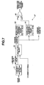
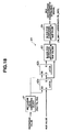
- the first embodiment of the present invention will be described with reference to Figs. 1 to 19B .
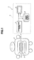
- an endoscope image pick-up apparatus or endoscope image pick-up system 1 comprises: an image pick-up unit 3 which is inserted in a body 2, then picks up an image of the body 2, and transmits image data thereof by radio; and an extra-corporeal unit 4 which receives the image data that is transmitted by radio from the image pick-up unit 3 and which stores and displays the image data.
- the image pick-up unit 3 comprises a capsule sealed container 5 which includes: blocks having an image pick-up block 13, which will be described later with reference to Fig. 2 ; and a battery 21.
- the image pick-up unit 3 supplies electric energy from the battery 21 to the image pick-up block 13 or the like, and transmits by radio, to the extra-corporeal unit 4 arranged outside the body, the image picked-up by the image pick-up block 13.
- the extra-corporeal unit 4 receives and demodulates the image data which is modulated and transmitted by radio from the image pick-up unit 3 from a communication block 7.
- the extra-corporeal unit 4 stores the demodulated image data to an image storing block 8, transmits the image data to a monitor 9, and displays the picked-up image onto a display surface of the monitor 9.
- the extra-corporeal unit 4 transmits the image data stored in the image storing block 8 to the monitor 9 side and displays the image.
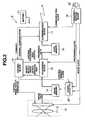
- the image pick-up unit 3 comprises: the image pick-up block 13 comprising an objective optical system 11 for forming an optical image of an examination target part in the body cavity into which the image pick-up unit 3 is inserted and a (solid-state) image pick-up device 12 such as a CCD or CMOS sensor; an image memory 14 which temporarily stores, via an A/D converter (not shown), digital image data picked-up by the image pick-up device 12; a processing block 15 which performs various processing of the image data stored in the image memory 14; and a data memory 16 which temporarily stores the data processed by the processing block 15.
- the image pick-up block 13 comprising an objective optical system 11 for forming an optical image of an examination target part in the body cavity into which the image pick-up unit 3 is inserted and a (solid-state) image pick-up device 12 such as a CCD or CMOS sensor
- an image memory 14 which temporarily stores, via an A/D converter (not shown), digital image data picked-up by the image pick-up device 12
- the image pick-up unit 3 comprises: a communication block 17 which reads the processed data from the data memory 16, transmits the read data to the extra-corporeal unit 4, and receives a command for controlling the image pick-up unit 3 from the extra-corporeal unit 4; and a frequency-dividing block 18 which generates clocks necessary for the blocks.
- the image pick-up unit 3 further comprises: a control block 19 which outputs a control signal to the blocks; a clock selector 20 which changes the processing speed of the image data; the battery 21 which supplies power for driving the blocks and electric devices such as the image pick-up device 12; and an illuminating block having a white LED (not shown) for illuminating the examination target part picked-up by the image pick-up block 13.
- the control block 19 outputs an image pick-up control signal for controlling the image pick-up operation, a processing control signal for controlling the processing, a communication control signal for controlling the communication, and a memory clock control signal for switching the frequency of an image clock for reading and writing data in the image memory 14, to the image pick-up device 12, the processing block 15, the communication block 17, and the clock selector 20, respectively.
- the processing block 15 detects a predetermined characteristic amount of the image from the image memory 14, which will be described later. Upon determining that the image is a valid portion, e.g., an affected part (or target image) based on the output of the characteristic amount, the processing block 15 outputs an affected part detecting signal to the control block 19. Upon determining that the image is invalid, the processing block 15 outputs an invalid image detecting signal to the control block 19. When a command is received from the extra-corporeal unit 4, the communication block 17 supplies the command to the control block 19.
- clocks generated by a single crystal oscillator 22 are frequency-divided by the frequency diving block 18, and a communication clock supplied to the communication block 17, a processing clock supplied to the processing block 15, an image clock supplied to the image pick-up device 12 and image memory 14 are generated, respectively.
- a user transmits the command from the extra-corporeal unit 4 to the control block 19 and thus the control block 19 transmits, to the processing block 15, a user control signal as a control signal transmitted by the user. Then, the processing operation of the processing block 15 is controlled.
- Fig. 3 shows a timing chart for the operation of the image pick-up unit 3.
- An image pick-up start pulse is generated from a CPU (not shown) forming a controller of the control block 19 in order to transmit the image for a predetermined period.
- the image pick-up block 13 starts the image pick-up operation by the image pick-up start pulses and the picked-up image data is stored in the image memory 14 (this processing is shown by S1 in Fig. 3 and, similarly, the subsequent processing is shown by S2 and the like).
- the processing block 15 After storing the image data corresponding to one screen, the processing block 15 reads the image data from the image memory 14 (S2), performs the processing such as compression and characteristic detection, and stores the processing result thereof in the data memory 16 (S3). After ending the processing, the data stored in the data memory 16 is transmitted to the communication block 17, is modulated by the communication block 17, and is transmitted extra-corporeal unit 4 (S4).
- the blocks have the sequence for preventing the simultaneous operation and thus the peak value of the consumption power from the battery 21 is reduced. That is, as shown by the bottom stage in Fig. 3 , the sequence includes the sequential processing for time-dividing the image pick-up processing for picking up the image and storing the picked-up image, the imaging processing for reading the stored image, imaging the data, and storing the resultant data to the data memory 16, and the transmitting processing for reading the imaged data and transmitting the data.
- the image clock is supplied to the image memory 14 and the like.
- the image signal needs a high-speed clock to some extent under the restriction of a frame rate.
- the processing block 15 is operated at the processing clock speed lower than the image clock speed.
- the communication block 17 is operated at the communication clock speed lower than the image clock speed.
- the power consumption of the image memory 14 is reduced by using the clock selector 20 for switching the high-speed and low-speed clocks upon picking up and processing the image signal. That is, the control block 19 controls the clock selector 20 by a memory clock control signal, with shifting so as to supply a high speed image clock upon the picking up the image or a low speed processing clock upon processing the data to the image memory 14.
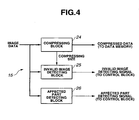
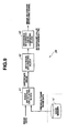
- Fig. 4 shows the structure of the processing block 15 according to the first embodiment.
- the image data inputted to the processing block is inputted to a compressing block 24 for compressing the image data, and an invalid image detecting block 25 and an affected part detecting block 26 forming characteristic amount detecting means for detecting the characteristic amount based on the image data and determining means for determining the validity.
- the compressing block 24 forms compressed data which is obtained by reducing the data amount by compressing the image data. Then, the compressing block 24 stores the compressed data to the data memory 16.
- the invalid image detecting block 25 detects the characteristic amount for the invalidity such as the white compression and black compression in the image and no change in image, and further determines whether or not the image is invalid. If it is detected that the image is invalid, the invalid image detecting block 25 outputs an image invalid detecting signal.
- the affected part detecting block 26 detects the characteristic amount for the affected part or the present or absence of the similar matter in the image data, and determines based on the detecting result whether or not the image is a target image. If it is detected that the image is the target image, the affected part detecting block 26 outputs an affected part detecting signal.
- the invalid image detecting signal and affected part detecting signal are inputted to the control block 19.
- the control block 19 controls the next image pick-up timing and the transmission of the image data based on the invalid image detecting signal and the affected part detecting signal.
- Fig. 5 shows a timing chart of the processing block 15.
- the processing block 15 does not transmit the image data and delays the next image pick-up period.
- the image which is determined as invalid and unnecessary is not subjected to the processing and the transmission (in this case, the status of the image pick-up unit 3 is referred to as an image invalid (status)).
- the image pick-up block 13 picks up the image for a predetermined period.
- the processing block 15 transmits the picked-up image as a normal-part image to the extra-corporeal unit 4 (in this case, the status of the image pick-up unit 3 is referred to as a normal-part image (status)).
- the processing block 15 reduces the image pick-up and transmitting periods so as to improve the diagnosis capacity, obtains a large amount of images around the affected part, and transmits the obtained image to the extra-corporeal unit 4 (in this case, the status of the image pick-up unit 3 is referred to as an affected-part image (status)).
- the processing block 15 detects the characteristic amount of the picked-up image, determines whether or not the image is valid, that is, whether the characteristic amount includes an invalid portion or valid portion, and controls a transmitting rate of the image data transmitted to the extra-corporeal unit 4 from the communication block 17 in accordance with the determining result.
- the processing block 15 controls the transmitting rate to be stopped. If it is determined that the image is the normal image, the processing block 15 controls the transmitting rate to the normal transmitting rate. Further, if it is determined that the image includes the valid portion such as the affected part, the processing block 15 controls the transmitting rate to be increased.
- the power of the battery 21 is consumed to transmit the image data with the large amount of information.
- the power consumption of the battery 21 is automatically adjusted in the proper state by increasing the transmitting rate of the valid image necessary for the user and then by reducing the transmitting rate of another image.
- control block 19 controls the image pick-up and transmitting periods by receiving the command from the extra-corporeal unit 4. Further, the control block 19 invalidates the control of the image pick-up and transmitting periods in the image pick-up unit 3 by receiving another command. The control operation based on the command from the extra-corporeal unit 4 is prior and the image pick-up and transmitting periods are controlled.
- the determining result is transmitted to the image pick-up unit 3 by the command, and the image pick-up and transmitting rates of the image pick-up unit 3 is controlled by the command.
- Fig. 6 shows the structure of the invalid image detecting block 25 shown in Fig. 4 .
- the invalid image detecting block 25 comprises: a luminance range detecting block 27; an image change detecting block 28; an image compressing size comparing block 29; and an OR circuit 30 to which the outputs signals therefrom are inputted.
- the luminance range detecting block 27 detects the average value of the luminance value, and outputs, to the OR circuit 30, an beyond-luminance-range detecting signal when it is extremely bright or extremely dark.
- the image change detecting block 28 detects that the image does not change, that is, whether the image pick-up unit 3 does not move or moves in the body based on the image data, average luminance value, and (image) compressing size, and outputs an image non-change detecting signal to the OR circuit 30.
- the image compressing size comparing block 29 compares the compressing size of image with a threshold value (Th_size). If it is determined that the compressing size of image is the threshold value (Th_size) or less, e.g., when the image is not focused with blur, the image compressing size comparing block 29 outputs, to the OR circuit 30, a signal for detecting the beyond-compressing-size of image. When any one of the beyond-luminance-range detecting signal, image non-change detecting signal and signal for detecting the beyond-compressing-size of image is detected, the invalid image detecting signal is outputted to the control block 19 via the OR circuit 30.
- symbols () denotes the operation for comparing the compressing size of image with the threshold value Th_size or less by the image compressing size comparing block 29 on the bottom.
- the foregoing comparing operation is similarly applied to another drawings.
- Fig. 7 shows the structure of the luminance range detecting block 27 shown in Fig. 6 .
- the luminance range detecting block 27 comprises: a luminance value integrating block 31 for integrating the luminance values of all the pixels of the inputted pixel signals; and a multiplying block 32 for calculating an average luminance value Yav of the image signal by dividing the integrated value of luminance values from the luminance value integrating block 31 by the number of pixels or multiplying it by 1/(number of pixels).
- the luminance range detecting block 27 further comprises: a black level threshold value comparing block 33 for comparing whether or not the average luminance value Yav outputted from the multiplying block 32 is lower than a threshold value (Th_Black) of the black level; a white level threshold value comparing block 34 for comparing whether or not it is higher than a threshold value (Th_White) of the white level; and an OR circuit 35 into which output signals from the black level threshold value comparing block 33 and white level threshold value comparing block 34 are inputted.
- a black level threshold value comparing block 33 for comparing whether or not the average luminance value Yav outputted from the multiplying block 32 is lower than a threshold value (Th_Black) of the black level
- a white level threshold value comparing block 34 for comparing whether or not it is higher than a threshold value (Th_White) of the white level
- an OR circuit 35 into which output signals from the black level threshold value comparing block 33 and white level threshold value comparing block 34 are inputted.
- the luminance range detecting block 27 outputs, from the OR circuit 35, a beyond-luminance-range signal indicating the determining result whether or not the image is extremely dark or extremely bright.
- Fig. 8 shows an example of the image change detecting block 28 shown in Fig. 6 .
- the image change detecting block 28 detects the image change based on the average luminance value Yav and the compressing size outputted from the compressing block 24.
- the average luminance value Yav and the compressing size are held in a previous-frame average luminance value holding block 36 and a previous-frame compressing size holding block 37 holding the average luminance value Yav and the compressing size of the frame before one frame.
- the average luminance value Yav before one frame and the average luminance value Yav of the current frame are inputted to an average luminance value comparing block 38.
- the compressing size before one frame and the compressing size of the current frame are inputted to a compressing size comparing block 39.
- the average luminance value comparing block 38 and compressing size comparing block 39 calculate the difference in average luminance values between the previous frame and the current frame and the difference in compressing sizes therebetween, respectively. If the absolutes of the difference are within a predetermined range, it is determined that the image does not change. Each non-change detecting signal of the average luminance value and compressing size is outputted to an AND circuit 40.
- the AND circuit 40 outputs the image non-change detecting signal by the AND operation of the two non-change detecting signals of the average luminance value and compressing size.
- Fig. 9 shows the image change detecting block 28 according to a modification.
- the image change detecting block 28 reads the image of the current frame from the image memory 14 shown in Fig. 2 , and the image of the previous frame and both the images are inputted to an image difference calculating block 41.
- the image difference calculating block 41 calculates the difference between the current frame and the previous frame every pixel, and inputs the resultant difference image to a difference integrating block 42, thus to calculate the integrated value.
- the integrated value is inputted to a difference integrated value comparing block 43.
- the difference integrated value comparing block 43 compares the integrated value of one frame with a predetermined threshold value (e.g., Th). If it is determined that the integrated value is lower than the threshold value, the difference integrated value comparing block 43 determines that the image does not change and outputs the image non-change detecting signal.
- a predetermined threshold value e.g., Th
- the difference integrated value comparing block 43 does not transmit the image data. Thus, the power consumption of the battery 21 is reduced.
- Fig. 10 shows the structure of the affected part detecting block 26 shown in Fig. 4 .
- the affected part detecting block 26 detects the affected part which color-changes from the normal part (ulcer, tumor, hemorrhage, etc.), and comprises: a specific color detecting block 46 and a color distribution characteristic detecting block 47 for receiving image data (R, G, and B); a specific-color change detecting block 48 for detecting the change in specific color based on the number of pixels of the specific color from the specific color detecting block 46; and an OR circuit 49 for receiving the output signals from the three blocks 46 to 48.
- a specific color detecting block 46 and a color distribution characteristic detecting block 47 for receiving image data (R, G, and B)
- a specific-color change detecting block 48 for detecting the change in specific color based on the number of pixels of the specific color from the specific color detecting block 46
- an OR circuit 49 for receiving the output signals from the three blocks 46 to 48.
- the specific color detecting block 46 for receiving the image data (R, G, and B) detects the affected part by determining whether or not the affected part has a predetermined number of pixels in the stated or specific color space. In this case, the specific color detecting block 46 outputs a specific-color detecting signal to the OR circuit 49.
- the specific-color change detecting block 48 detects the affected part in the case that number of pixels in the stated color space peculiar to the affected part, namely number of pixels in the specific color has changed. In this case, the specific-color change detecting block 48 outputs a specific-color change detecting signal to the OR circuit 49.
- the color distribution characteristic detecting block 47 calculates the hue and saturation of the inputted image data, detects the affected part based on the characteristics and outputs a color distribution characteristic detecting signal to the OR circuit 49 in this case.
- the change of specific color and the color distribution are detected in parallel therewith and thus the color-changed affected part having some individual difference can accurately be detected.
- the affected part detecting signal is outputted to the control block 19 via the OR circuit 49.
- Fig. 11 shows the structure of the specific color detecting block 46.
- the specific color detecting block 46 compares the values of the image signals (R, G, and B shown in Fig. 10 according to the first embodiment) with the threshold value, that is, detects whether or not they are within a predetermined range by an image data comparing block 51.
- the image data comparing block 51 compares the values of the image signals (R, G, and B) with Th_Min ⁇ R ⁇ Th_Max, Th_Min ⁇ G ⁇ Th_Max, and Th_Min ⁇ B ⁇ Th_Max. Further, image data comparing block 51 outputs the resultant data to the AND circuit and obtains the result of the logical product from the AND circuit.
- the image data comparing block 51 When all the image signals (R, G, and B) are within the predetermined range, the image data comparing block 51 outputs the resultant data as the specific-color pixel to a specific-color pixel number counting block 52 at the next stage. Further, the specific-color pixel number counting block 52 counts the number of pixels.
- the specific-color pixel number counting block 52 detects the value (number of specific-color pixels) shared by the specific-color pixel in the image.
- the number of specific-color pixels is inputted to the specific-color change detecting block 48 shown in Fig. 10 and are inputted to a specific-color pixel number comparing block 53 shown in Fig. 11 .
- the specific-color pixel number comparing block 53 compares the number of specific-color pixels with a predetermined threshold value Th_Num, and determines the detection of the specific color of the affected part if it is determined that the number of specific-color colors is Th_Num or more.
- the (value of) the number of specific-color pixels is outputted to the specific color detecting block 46.
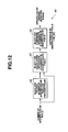
- Fig. 12 shows the structure of the specific-color change detecting block 48 shown in Fig. 10 .
- a block 56 for holding the number of specific-color pixels in the previous frame and a block 57 for calculating the difference in number of specific-color pixels form the specific-color change detecting block 48.
- the number of specific-color pixels are inputted to the block 56 for holding the number of specific-color pixels in the previous frame and block 57 for calculating the difference in number of specific-color pixels from the specific color detecting block 46.
- the block 56 for holding the number of specific-color pixels in the previous frame holds the number of specific-color pixels of the previous frame.
- the block 57 for calculating the difference in number of specific-color pixels calculates the difference in number of specific-color pixels between the previous frame and the current frame, and inputs the calculating result to a block 58 for comparing the difference in number of specific-color pixels.
- the block 58 for comparing the difference in number of specific-color pixels compares the difference with a threshold value Th_Dif, that is, determines whether or not the difference is a predetermined value or more. If it is determined that the difference is the threshold value Th_Dif or more, the change in specific color is detected and a specific-color change detecting signal is outputted.
- Fig. 13 shows the structure of the color distribution characteristic detecting block 47 shown in Fig. 10 .
- the color distribution characteristic detecting block 47 converts the inputted R-, G-, and B-images into the hue and saturation by a color space converting block 61.
- a hue histogram calculating block 62 and a saturation histogram calculating block 63 detect the histograms (frequency distributions) of hue and saturation.
- (Data of) the hue histogram and saturation histogram are inputted to a hue distribution characteristic detecting block 64 and a saturation distribution characteristic detecting block 65.
- the hue distribution characteristic detecting block 64 and saturation distribution characteristic detecting block 65 detect whether or not the histograms have predetermined characteristics, which will be described later. If it is determined that the histograms have the predetermined characteristics, the hue distribution characteristic detecting block 64 and saturation distribution characteristic detecting block 65 output, to an OR circuit 66, a signal for detecting the characteristic of the hue distribution and a signal for detecting the characteristic of the saturation distribution.
- a signal for detecting the characteristic of the color distribution is outputted via the OR circuit 66.
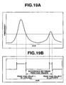
- Fig. 14 shows examples of the characteristics of the color distribution of the hue and saturation of the affected part.
- Figs. 14A and 14B show the example of characteristics of the hue and saturation at the normal part. Since the internal organ photographed at the normal part is uniform, the hue and saturation have the peak at one place.
- Figs. 14C and 14D show examples of the characteristics of the hue and saturation in the case of photographing the color-changed part in which the changed color is generated by the ulcer or tumor. Since the hue at a part of the image is different, another peak is generated in addition to the peak of the normal part.
- Figs. 14E and 14F show example of the characteristics of the hue and saturation in the case of photographing a part in which the color change is caused by the hemorrhage or the like. Although the hue is not changed in this case, the hue at the normal part is different from that of the hemorrhage. Therefore, the hue has another peak in addition to the peak which is generated at the normal part.
- the histograms of hue and saturation have a plurality of peaks at a predetermined distance.
- Fig. 15 shows one example of the color space converting block 61 shown in Fig. 13 .
- the color space converting block 61 converts the image data inputted in the RGB space into the hue (H) and saturation (S).
- the image data is inputted to a Max value detecting block 71 and a Min value detecting block 72.
- the Max value detecting block 71 and the Min value detecting block 72 compare the R-, G-, and B-values of the pixels in the inputted image data, select the maximum value and the minimum value, and output the selected values as a Max value and a Min value to a saturation calculating block 73 and a hue calculating block 74.
- the Max value detecting block 71 outputs, to the hue calculating block 74, a Max_RGB signal indicating that the Max value is any of R, G, and B.
- the image data is inputted to the hue calculating block 74.
- the saturation calculating block 73 calculates the following saturation S.
- Saturation S Max value - Min value / Max value The saturation is calculated based on the above-mentioned Max value and Min value.
- the hue calculating block 74 calculates the hue value by the following calculation based on a Max_RGB signal indicating the Max value is any of R, G, and B.
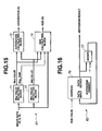
- Fig. 16 shows the structure of the hue histogram calculating block 62 shown in Fig. 13 .
- the hue histogram calculating block 62 comprises a histogram memory 76 and an adder 77 for adding one.
- the hue value is inputted to the address of the histogram memory 76. After inputting the hue value, the value stored in the address is incremented by 1.
- Figs. 17A and 17B show the operation of the histogram memory 76.
- Fig. 17A shows the case of inputting a hue value.
- Data N stored in the address A is incremented by 1 and data (N + 1) is stored.
- Fig. 17B shows the case of inputting a hue value.
- Data M stored in the address B is incremented by 1, and data (M + 1) is added.
- the saturation histogram calculating block 63 shown in Fig. 13 has the above-mentioned structure. Thus, the structure and operation of the saturation histogram calculating block 63 are not described here.
- Fig. 18 shows the structure of hue distribution characteristic detecting block 64 in Fig. 13 .
- the hue distribution characteristic detecting block 64 comprises: a histogram value comparing block 81 for comparing a histogram value Hist with a predetermined threshold value Th_Hist; latch circuits 82a and 82b for latching the corresponding hue values when the comparison result is the threshold value Th_Hist or more; and a block 83 for calculating the difference in hue values for calculating the difference between the latched hue values; and a block 84 for comparing the difference in hue values for comparing whether or not the difference is within a predetermined range.
- Fig. 19A shows the histogram of the inputted hue values.
- Fig. 19B shows an explanatory diagram of the operation for comparing the histogram value of the hue value with the threshold value and for detecting the distance between the hue values.
- the histogram value comparing block 81 compares the histogram value of the hue value with the threshold value, thereby outputting the pulses near the position of the peak value of the histogram.
- the latch circuits 82a and 82b shown in Fig. 18 latch the corresponding hue values by the pulses.
- the block 83 for calculating the difference in hue values at the next stage calculates the distance between the hue values by using the latched hue values.
- the distance between the peak hue values is obtained.
- the image has a portion with the hue different from that of the normal image and the block 84 for comparing the difference in hue values outputs a signal for detecting the characteristic of the hue distribution.
- the saturation distribution characteristic detecting block 65 shown in Fig. 13 has the similar structure.
- the predetermined characteristic amount such as the number of pixels having the specific color in the image is detected based on the picked-up image. It is determined whether or not the detecting result is valid.
- the rate for transmitting the picked-up image to the extra-corporeal unit 4 is controlled and it is possible to set, to the proper state, the power consumption for transmitting the image with the large load by the battery 21.
- the first embodiment it is possible to efficiently obtain the necessary image on the extra-corporeal unit 4 side. It is advantageous to eliminate or extremely reduce the troublesome operation for extracting the necessary image from the unneeded images according to the conventional art.
- the detailed image for diagnosis can be transmitted to the extra-corporeal unit 4 without suppressing the image transmitting rate upon picking up the valid image. Further, the electric energy of the battery 21 can effectively be used and the image for diagnosis can effectively be collected.
- the affected part such as changed color and hemorrhage is accurately detected without transmitting the unnecessary image.
- the detailed image for diagnosis is transmitted and the image diagnostic environment of the operator can be improved.
- Fig. 20 shows the structure of the processing block 15 according to the second embodiment.
- the image data inputted to the processing block 15 is inputted to an image size reducing block 85, the invalid image detecting block 25, and the affected part detecting block 26.
- the image size reducing block 85 controls the reduction of image size under the control of the invalid image detecting block 25 and the affected part detecting block 26.
- the image size reducing block 85 reduces the image size by the invalid image detecting signal from the invalid image detecting block 25 and suppresses the reduction of image size upon inputting the affected part detecting signal from the affected part detecting block 26.
- the output image from the image size reducing block 85 is inputted to a compressing block 86.
- the compressing block 86 changes the compressing ratio by a control signal from the affected part detecting block 26 and outputs the compressed image to the communication block 17 shown in Fig. 2 .
- the compressing block 86 reduces the compressing ratio of the image data and transmits, to the communication block 17, the compressed data which is compressed by the low compressing ratio upon inputting the affected part detecting signal from the affected part detecting block 26.
- the communication block 17 transmits the compressed data to the extra-corporeal unit 4.
- the invalid image detecting block 25 detects the invalid image (white compression, black compression, and non-change of obtained image). Further, the affected part detecting block 26 detects the absence or presence of the affected part or its similar part based on the image data.
- the reducing ratio of image size and the compressing ratio are controlled by a user control signal outputted from the control block 19 based on a command received from the extra-corporeal unit 4. Further, The on/off operation of the control is performed by the invalid image signal and the affected part detecting signal. As mentioned above, the compressing ratio of the image size is controlled by inputting the command from the user.
- Fig. 21 shows a timing cart of the processing block 15.
- the image size is minimized and the compressing ratio is maximized.
- the amount of transmitted data is suppressed to the minimum level. Because, mainly, information at the minimum level is transmitted to monitor the state of image pick-up unit 3.
- the image size and the compressing ratio are set to the middle level. Because the image at-the normal part for reference is transmitted to the extra-corporeal unit 4.
- the image size is not reduced because of increasing the amount of information of the affected-part image. Further, compressing ratio is reduced and the image is externally outputted with the highest quality.
- the affected part detecting block 26 and the invalid image detecting block 25 shown in Fig. 20 have the same structures as those according to the first embodiment and therefore a description thereof is omitted.
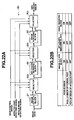
- Fig. 22A shows the structure of the image size reducing block 85 according to the second embodiment.
- the image size reducing block 85 comprises: an image cut-out block 87; a Bit-length reducing block 88; an image reducing block 89; and selectors 90a, 90b, and 90c for selecting the image from the blocks.
- the image size reducing block 85 controls the operation such as the size reduction from the original image based on the affected part detecting signal, invalid image signal, and user control signal.
- the determining result of the invalid image signal and affected part detecting signal specifically, depending on the cases of the invalid image, picking up the normal part, and detecting the affected part, the image whose size is reduced from the original image is outputted via the selectors 90a to 90c.
- the image cut-out block 87 reduces the number of pixels by decreasing an angle of view (pixel size of the image) by cutting out the image.
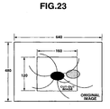
- Fig. 23 shows an example of cutting out the image by the image cut-out block 87.
- only the center of the original image having (640 x 480) pixels is cut out.
- the center specifically, the image having (160 x 120) pixels is outputted.
- the cut-out image is outputted to the latter-stage side.
- the invalid image signal does not detect that the image is invalid, the original image from which the image is not cut out is outputted to the latter-stage side.
- the bit-length reducing block 88 shown in Fig. 22A reduces the image size by decreasing the bit length of the image.
- the gradation of 8 bits is reduced to that of 4 bits, thereby reducing the bit length of the image.
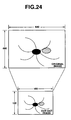
- the image reducing block 89 thins out the pixels, and this example is shown in Fig. 24 .
- the image having (640 x 480) pixels shown on the top side is reduced to the image having the (160 x 120) pixels by the thinning out the pixels as shown on the bottom side in Fig. 24 . Since the simple thinning-out operation of pixels normally causes the problem on the image quality, the processing with the interpolation using the algorithm such as bi-linear and bi-cubic is performed.
- the image when it is determined that the image is invalid, the image is transmitted at the level for determining the state of the image pick-up unit 3, namely, the occurrence of white compression, black compression or stop.
- the image cut-out block cuts out the image of one part of the angle of view, and the Bit length is 4 bits by the Bit length reduction, thus to reduce the image.
- any image size is not reduced because of using the image for diagnosis with the highest image quality.
- the compressing block 86 compresses the image data whose image size is reduced if necessary.
- the image compression uses JPEG.
- the compressing ratio can arbitrarily be changed by a table of compressing parameters.
- Fig. 25 shows the schematic structure of the compressing block 86 shown in Fig. 20 .
- the compressing block 86 comprises: a high-compressing table 91, a middle-compressing table 92, and a low-compressing table 93 which compress the data by high, middle, and low compressing ratios, respectively; a selector 94 for selecting one of the high-, middle-, and low-compressing tables 91 to 93; and a JPEG block 95 for JPEG-compressing the data by the selecting compressing table.
- the compressing table Upon inputting the invalid image detecting signal, the compressing table is switched to that with the high compressing ratio. Upon inputting the affected part detecting signal, the compressing table is switched to that with the low compressing ratio. Upon detecting neither the invalid image detecting signal nor the affected part detecting signal, the compressing table with middle compressing ratio is used.
- the image size and the compressed data size are switched depending on the determining result of the image importance (validity) and the compression and communication time is reduced.
- the consumption power is reduced and the image with high quality necessary for diagnosis can be transmitted.
- the above control suppresses the power consumption of the battery 21 in the case of the unnecessary image and further enables the long use.
- the present invention can variously be modified. According to the first and second embodiments, the transmitting interval of the image data and the size of transmitted data are independently controlled. However, the combination of the above two control operations can be used.
- the endoscope image pick-up apparatus of the present invention picks up the image in the body by the image pick-up unit inserted in the body and transmits the image by radio to the extra-corporeal unit which is arranged outside the body.
- the amount of images transmitted to the extra-corporeal unit side is properly controlled, thereby obtaining the image suitable to the endoscopic examination.
Claims (8)
- Appareil (1) de capture d'image d'endoscope pour capturer une image d'un corps (2) par une unité (3) de capture d'image insérée dans le corps et pour transmettre l'image par radio jusqu'à une unité (4) extracorporelle qui est agencée à l'extérieur du corps (2),
dans lequel l'unité (3) de capture d'image comprend :un moyen (13) de capture d'image adapté à capturer une image ;des moyens (17, 19) de transmission de données adaptés à transmettre l'image obtenue par le moyen (13) de capture d'image jusqu'à l'unité (4) extracorporelle à une pluralité de débits de transmission ;des moyens (25, 26) de détection de quantité de caractéristiques adaptés à détecter une quantité prédéterminée de caractéristiques sur la base de l'image ; etdes moyens (25, 26) de détermination adaptés à déterminer une image valide sur la base d'une sortie des moyens de détection de quantité de caractéristiques dans lequel les moyens (25, 26) de détermination comprennent :un moyen (25) de détermination d'invalidité adapté à déterminer si l'image est invalide ou valide ; et
un moyen (26) de détermination d'image cible adapté à déterminer si l'image est ou non une image cible, l'image cible étant une image d'une région d'intérêt du corps, dans lequel
les moyens (17, 19) de transmission de données sont adaptés à contrôler le débit de transmission de données en fonction d'un résultat de détermination des moyens (25, 26) de détermination, dans lequel le débit de transmission de données est augmenté si l'image est une image cible, et stoppé si l'image n'est pas une image cible, et
dans lequel l'unité (3) de capture d'image comprend des moyens (17, 19) de réception de commandes adaptés à recevoir une pluralité de types de commandes de l'unité (4) extracorporelle, et
les moyens (17, 19) de transmission de données sont adaptés à contrôler un débit de transmission de données sur la base de la commande reçue par les moyens (17, 19) de réception de commandes, et à invalider le contrôle du débit de transmission de données par les moyens (25, 26) de détermination sur la base d'une autre commande reçue par les moyens (17, 19) de réception de commandes. - Appareil (1) de capture d'image d'endoscope selon la revendication 1, dans lequel les moyens (25, 26) de détermination sont adaptés à déterminer la validité d'image à une pluralité de niveaux sur la base de la combinaison des résultats de détermination, et à délivrer en sortie le résultat de détermination.
- Appareil (1) de capture d'image d'endoscope selon la revendication 1, dans lequel les moyens (25, 26) de détection de quantité de caractéristiques comprennent un moyen (46) de détection de nombre de pixels adapté à détecter le nombre de pixels ayant une couleur spécifique dans l'image comme la quantité de caractéristiques, et
les moyens (25, 26) de détermination sont adaptés à déterminer que l'image est valide lorsque le nombre de pixels de couleur spécifique est une valeur de seuil prédéterminée ou plus. - Appareil (1) de capture d'image d'endoscope selon la revendication 1, dans lequel les moyens (25, 26) de détection de quantité de caractéristiques comprennent :un moyen (46) de détection de nombre de pixels adapté à détecter le nombre de pixels ayant une couleur spécifique dans l'image ;un moyen (56) de stockage de nombre de pixels adapté à stocker le nombre détecté de pixels ; etdes moyens (57, 58) de comparaison et de calcul de nombre de pixels adaptés à comparer et calculer le nombre passé de pixels stockés dans le moyen (56) de stockage de nombre de pixels et le nombre courant de pixels et à délivrer en sortie la quantité de changement du nombre de pixels comme la quantité de caractéristiques, etles moyens (25, 26) de détermination sont adaptés à déterminer que l'image est valide lorsque la quantité de changement du nombre de pixels est une valeur de seuil prédéterminée ou plus.
- Appareil (1) de capture d'image d'endoscope selon la revendication 1, dans lequel les moyens (25, 26) de détection de quantité de caractéristiques comprennent :un moyen (47) de détection de distribution de couleur adapté à détecter la caractéristique de distribution de couleur dans l'image ; etdes moyens (64, 65) de comparaison et de calcul de distribution de couleur adaptés à comparer et calculer la distribution de couleur détectée et une distribution de couleur prédéterminée et à délivrer en sortie une erreur de la distribution de couleur comme la quantité de caractéristiques, etles moyens (25, 26) de détermination sont adaptés à déterminer que l'image est valide lorsque l'erreur de la distribution de couleur est une valeur de seuil prédéterminée ou moins.
- Appareil (1) de capture d'image d'endoscope selon la revendication 1, dans lequel les moyens (25, 26) de détection de quantité de caractéristiques comprennent un moyen (27) de calcul de valeur moyenne de luminance adapté à détecter une valeur moyenne de valeurs de luminance dans l'image comme la quantité de caractéristiques, et
les moyens (25, 26) de détermination sont adaptés à déterminer que l'image est valide lorsque la valeur moyenne de luminance est à l'intérieur d'une plage prédéterminée. - Appareil (1) de capture d'image d'endoscope selon la revendication 1, dans lequel les moyens (25, 26) de détection de quantité de caractéristiques comprennent :un moyen (27) de calcul de valeur moyenne de luminance adapté à détecter une valeur moyenne de valeurs de luminance dans l'image ;un moyen (36) de stockage de valeur moyenne de luminance adapté à stocker la valeur moyenne de luminance ; etun moyen (38) de comparaison et de calcul de valeurs moyennes de luminance adapté à comparer et calculer la valeur moyenne de luminance passée stockée dans le moyen (36) de stockage de valeur moyenne de luminance et la valeur moyenne de luminance courante et à délivrer en sortie la quantité de changement de la valeur moyenne de luminance comme la quantité de caractéristiques, etles moyens (25, 26) de détermination sont adaptés à déterminer que l'image est valide lorsque la quantité de changement de la valeur moyenne de luminance est une valeur de seuil prédéterminée ou plus.
- Appareil (1) de capture d'image d'endoscope selon la revendication 1, dans lequel les moyens (25, 26) de détection de quantité de caractéristiques comprennent :un moyen (37) de stockage d'image adapté à stocker l'image capturée ; etun moyen (38) de calcul de différence de données d'image adapté à calculer la différence entre les données d'image passées stockées dans le moyen de stockage d'image et les données d'image courantes et à délivrer en sortie la différence calculée comme la quantité de caractéristiques, etles moyens (25, 26) de détermination sont adaptés à déterminer que l'image est valide lorsque la différence est une valeur prédéterminée ou plus.
Priority Applications (1)
| Application Number | Priority Date | Filing Date | Title |
|---|---|---|---|
| EP07015701.1A EP1897484B1 (fr) | 2004-03-04 | 2004-03-04 | Dispositif endoscopique de capture d'image |
Applications Claiming Priority (1)
| Application Number | Priority Date | Filing Date | Title |
|---|---|---|---|
| PCT/JP2004/002701 WO2005084520A1 (fr) | 2004-03-04 | 2004-03-04 | Dispositif de detection d’image endoscopique |
Related Child Applications (2)
| Application Number | Title | Priority Date | Filing Date |
|---|---|---|---|
| EP07015701.1A Division EP1897484B1 (fr) | 2004-03-04 | 2004-03-04 | Dispositif endoscopique de capture d'image |
| EP07015701.1A Division-Into EP1897484B1 (fr) | 2004-03-04 | 2004-03-04 | Dispositif endoscopique de capture d'image |
Publications (3)
| Publication Number | Publication Date |
|---|---|
| EP1652465A1 EP1652465A1 (fr) | 2006-05-03 |
| EP1652465A4 EP1652465A4 (fr) | 2006-09-27 |
| EP1652465B1 true EP1652465B1 (fr) | 2014-06-25 |
Family
ID=34917820
Family Applications (2)
| Application Number | Title | Priority Date | Filing Date |
|---|---|---|---|
| EP07015701.1A Expired - Fee Related EP1897484B1 (fr) | 2004-03-04 | 2004-03-04 | Dispositif endoscopique de capture d'image |
| EP04717269.7A Expired - Fee Related EP1652465B1 (fr) | 2004-03-04 | 2004-03-04 | Dispositif de detection d'image endoscopique |
Family Applications Before (1)
| Application Number | Title | Priority Date | Filing Date |
|---|---|---|---|
| EP07015701.1A Expired - Fee Related EP1897484B1 (fr) | 2004-03-04 | 2004-03-04 | Dispositif endoscopique de capture d'image |
Country Status (3)
| Country | Link |
|---|---|
| EP (2) | EP1897484B1 (fr) |
| CN (1) | CN100438815C (fr) |
| WO (1) | WO2005084520A1 (fr) |
Families Citing this family (7)
| Publication number | Priority date | Publication date | Assignee | Title |
|---|---|---|---|---|
| JP5242381B2 (ja) * | 2006-03-16 | 2013-07-24 | オリンパスメディカルシステムズ株式会社 | 医療用画像処理装置及び医療用画像処理方法 |
| CN100382743C (zh) * | 2006-05-23 | 2008-04-23 | 重庆大学 | 基于jpeg2000的按需式无线内窥镜胶囊 |
| JP2007319442A (ja) * | 2006-06-01 | 2007-12-13 | Fujifilm Corp | カプセル内視鏡システム、および画像処理装置 |
| JP5078486B2 (ja) * | 2007-07-26 | 2012-11-21 | オリンパスメディカルシステムズ株式会社 | 医療用画像処理装置及び医療用画像処理装置の作動方法 |
| JP2009226066A (ja) * | 2008-03-24 | 2009-10-08 | Olympus Corp | カプセル型医療装置 |
| DE102008047213A1 (de) * | 2008-09-15 | 2010-04-15 | Siemens Aktiengesellschaft | Blasenfüllstandssensor |
| CN112274115A (zh) * | 2020-07-03 | 2021-01-29 | 母宗军 | 集成化胃部环境探测平台及方法 |
Citations (1)
| Publication number | Priority date | Publication date | Assignee | Title |
|---|---|---|---|---|
| EP1492352A2 (fr) * | 2003-06-26 | 2004-12-29 | Given Imaging Ltd. | Dispositf, méthode und système pour la transmission réduite d'images |
Family Cites Families (13)
| Publication number | Priority date | Publication date | Assignee | Title |
|---|---|---|---|---|
| US5387928A (en) | 1990-05-29 | 1995-02-07 | Fuji Photo Optical Co., Ltd. | Electronic endoscope system having both still and moving images |
| JP3785520B2 (ja) * | 1997-03-19 | 2006-06-14 | コニカミノルタホールディングス株式会社 | 電子カメラ |
| IL122602A0 (en) * | 1997-12-15 | 1998-08-16 | Tally Eitan Zeev Pearl And Co | Energy management of a video capsule |
| JP2000350085A (ja) * | 1999-06-01 | 2000-12-15 | Olympus Optical Co Ltd | 電子的撮像装置 |
| JP4697500B2 (ja) * | 1999-08-09 | 2011-06-08 | ソニー株式会社 | 送信装置および送信方法、受信装置および受信方法、並びに記録媒体 |
| JP2002118756A (ja) * | 2000-10-10 | 2002-04-19 | Ricoh Co Ltd | データ転送方法とデータ転送装置と画像処理装置及び画像形成装置 |
| US6939292B2 (en) | 2001-06-20 | 2005-09-06 | Olympus Corporation | Capsule type endoscope |
| JP2003023637A (ja) * | 2001-07-06 | 2003-01-24 | Sony Corp | 画像符号化方法および画像符号化装置 |
| JP2003037768A (ja) * | 2001-07-24 | 2003-02-07 | Nikon Corp | 電子カメラ |
| US20030043263A1 (en) * | 2001-07-26 | 2003-03-06 | Arkady Glukhovsky | Diagnostic device using data compression |
| JP3974769B2 (ja) * | 2001-11-06 | 2007-09-12 | オリンパス株式会社 | カプセル型医療装置 |
| JP2004023656A (ja) * | 2002-06-19 | 2004-01-22 | Canon Inc | 画像処理装置、画像処理方法、及び、プログラム |
| CN100341459C (zh) * | 2002-08-05 | 2007-10-10 | 中国人民解放军总医院 | 医用无线电胶囊 |
-
2004
- 2004-03-04 EP EP07015701.1A patent/EP1897484B1/fr not_active Expired - Fee Related
- 2004-03-04 EP EP04717269.7A patent/EP1652465B1/fr not_active Expired - Fee Related
- 2004-03-04 WO PCT/JP2004/002701 patent/WO2005084520A1/fr not_active Application Discontinuation
- 2004-03-04 CN CNB2004800316719A patent/CN100438815C/zh not_active Expired - Fee Related
Patent Citations (1)
| Publication number | Priority date | Publication date | Assignee | Title |
|---|---|---|---|---|
| EP1492352A2 (fr) * | 2003-06-26 | 2004-12-29 | Given Imaging Ltd. | Dispositf, méthode und système pour la transmission réduite d'images |
Also Published As
| Publication number | Publication date |
|---|---|
| EP1652465A4 (fr) | 2006-09-27 |
| EP1897484A2 (fr) | 2008-03-12 |
| CN1874713A (zh) | 2006-12-06 |
| EP1652465A1 (fr) | 2006-05-03 |
| EP1897484A3 (fr) | 2009-05-06 |
| CN100438815C (zh) | 2008-12-03 |
| EP1897484B1 (fr) | 2015-12-30 |
| WO2005084520A1 (fr) | 2005-09-15 |
Similar Documents
| Publication | Publication Date | Title |
|---|---|---|
| US7195588B2 (en) | Endoscope image pick-up apparatus | |
| JP4583704B2 (ja) | 内視鏡撮像装置 | |
| US11006817B2 (en) | Endoscope system for endoscope image processing and image transmission | |
| EP1806091A1 (fr) | Procede de traitement d images et dispositif d endoscope a capsule | |
| US9560956B2 (en) | Device, system and method of displaying in-vivo images at variable rate | |
| CN101370423B (zh) | 接收装置 | |
| US6441845B1 (en) | Image pickup apparatus enlarging a dynamic range of an image pickup signal | |
| EP1618833A1 (fr) | Dispositif et système de prise de vue in vivo | |
| JP3887453B2 (ja) | 内視鏡装置 | |
| US20090167908A1 (en) | Image pickup apparatus, image display apparatus, and image display system | |
| EP1652465B1 (fr) | Dispositif de detection d'image endoscopique | |
| CN109008909B (zh) | 一种低功耗胶囊内窥镜图像采集及三维重建系统 | |
| KR20070116636A (ko) | 화상 표시 장치 | |
| EP1681009A1 (fr) | Dispositif de traitement d'images, procede de traitement d'images et programme de traitement d'images | |
| US11595621B2 (en) | Endoscope apparatus, endoscope, and image generation method | |
| JP7052022B2 (ja) | 内視鏡装置、内視鏡およびプロセッサならびに内視鏡装置の作動方法 | |
| CN110381806B (zh) | 电子内窥镜系统 | |
| KR100777518B1 (ko) | 내시경 촬상 장치 | |
| US20220000336A1 (en) | Video processor, endoscope system, endoscope, and image processing method | |
| JP7237095B2 (ja) | ビデオプロセッサ、内視鏡システムおよび内視鏡装置の画像処理装置の作動方法 | |
| US20220000335A1 (en) | Video processor, image processing method, endoscope, and endoscope system | |
| US11877070B2 (en) | Surgical camera system with high dynamic range and fluorescent imaging | |
| WO2023003981A1 (fr) | Système de caméra chirurgicale à plage dynamique élevée |
Legal Events
| Date | Code | Title | Description |
|---|---|---|---|
| PUAI | Public reference made under article 153(3) epc to a published international application that has entered the european phase |
Free format text: ORIGINAL CODE: 0009012 |
|
| 17P | Request for examination filed |
Effective date: 20060124 |
|
| AK | Designated contracting states |
Kind code of ref document: A1 Designated state(s): DE FR GB |
|
| A4 | Supplementary search report drawn up and despatched |
Effective date: 20060828 |
|
| RIC1 | Information provided on ipc code assigned before grant |
Ipc: A61B 1/04 20060101AFI20060822BHEP |
|
| RIN1 | Information on inventor provided before grant (corrected) |
Inventor name: HOMAN, MASATOSHI Inventor name: KOTODA, KAORUC/O OLYMPUS INTEL. PTY SCES CO.,LTD Inventor name: AZUMA, MOTOO |
|
| 17Q | First examination report despatched |
Effective date: 20070426 |
|
| DAX | Request for extension of the european patent (deleted) | ||
| RBV | Designated contracting states (corrected) |
Designated state(s): DE FR GB |
|
| REG | Reference to a national code |
Ref country code: DE Ref legal event code: R079 Ref document number: 602004045347 Country of ref document: DE Free format text: PREVIOUS MAIN CLASS: A61B0001040000 Ipc: A61B0001000000 |
|
| GRAP | Despatch of communication of intention to grant a patent |
Free format text: ORIGINAL CODE: EPIDOSNIGR1 |
|
| RIC1 | Information provided on ipc code assigned before grant |
Ipc: H04N 5/77 20060101ALI20140117BHEP Ipc: A61B 1/00 20060101AFI20140117BHEP Ipc: A61B 5/00 20060101ALI20140117BHEP Ipc: H04N 5/232 20060101ALI20140117BHEP Ipc: A61B 1/04 20060101ALI20140117BHEP Ipc: H04N 9/804 20060101ALI20140117BHEP Ipc: H04N 5/225 20060101ALI20140117BHEP Ipc: A61B 5/07 20060101ALI20140117BHEP |
|
| INTG | Intention to grant announced |
Effective date: 20140207 |
|
| GRAS | Grant fee paid |
Free format text: ORIGINAL CODE: EPIDOSNIGR3 |
|
| GRAA | (expected) grant |
Free format text: ORIGINAL CODE: 0009210 |
|
| RIN1 | Information on inventor provided before grant (corrected) |
Inventor name: HOMAN, MASATOSHI Inventor name: KOTOUDA, KAORU C/O OLYMPUS INTEL. PTY SCES CO.,LTD Inventor name: AZUMA, MOTOO |
|
| AK | Designated contracting states |
Kind code of ref document: B1 Designated state(s): DE FR GB |
|
| REG | Reference to a national code |
Ref country code: GB Ref legal event code: FG4D |
|
| REG | Reference to a national code |
Ref country code: DE Ref legal event code: R096 Ref document number: 602004045347 Country of ref document: DE Effective date: 20140807 |
|
| REG | Reference to a national code |
Ref country code: DE Ref legal event code: R097 Ref document number: 602004045347 Country of ref document: DE |
|
| PLBE | No opposition filed within time limit |
Free format text: ORIGINAL CODE: 0009261 |
|
| STAA | Information on the status of an ep patent application or granted ep patent |
Free format text: STATUS: NO OPPOSITION FILED WITHIN TIME LIMIT |
|
| 26N | No opposition filed |
Effective date: 20150326 |
|
| GBPC | Gb: european patent ceased through non-payment of renewal fee |
Effective date: 20150304 |
|
| REG | Reference to a national code |
Ref country code: FR Ref legal event code: ST Effective date: 20151130 |
|
| PG25 | Lapsed in a contracting state [announced via postgrant information from national office to epo] |
Ref country code: GB Free format text: LAPSE BECAUSE OF NON-PAYMENT OF DUE FEES Effective date: 20150304 |
|
| PG25 | Lapsed in a contracting state [announced via postgrant information from national office to epo] |
Ref country code: FR Free format text: LAPSE BECAUSE OF NON-PAYMENT OF DUE FEES Effective date: 20150331 |
|
| PGFP | Annual fee paid to national office [announced via postgrant information from national office to epo] |
Ref country code: DE Payment date: 20170228 Year of fee payment: 14 |
|
| REG | Reference to a national code |
Ref country code: DE Ref legal event code: R119 Ref document number: 602004045347 Country of ref document: DE |
|
| PG25 | Lapsed in a contracting state [announced via postgrant information from national office to epo] |
Ref country code: DE Free format text: LAPSE BECAUSE OF NON-PAYMENT OF DUE FEES Effective date: 20181002 |