EP1651335B1 - Mischsystem - Google Patents
Mischsystem Download PDFInfo
- Publication number
- EP1651335B1 EP1651335B1 EP04739561A EP04739561A EP1651335B1 EP 1651335 B1 EP1651335 B1 EP 1651335B1 EP 04739561 A EP04739561 A EP 04739561A EP 04739561 A EP04739561 A EP 04739561A EP 1651335 B1 EP1651335 B1 EP 1651335B1
- Authority
- EP
- European Patent Office
- Prior art keywords
- mixing
- mixing system
- flow
- medium
- vanes
- Prior art date
- Legal status (The legal status is an assumption and is not a legal conclusion. Google has not performed a legal analysis and makes no representation as to the accuracy of the status listed.)
- Expired - Lifetime
Links
- 238000002156 mixing Methods 0.000 title claims abstract description 193
- 238000002347 injection Methods 0.000 claims abstract description 41
- 239000007924 injection Substances 0.000 claims abstract description 41
- 239000012429 reaction media Substances 0.000 claims abstract description 31
- 238000011144 upstream manufacturing Methods 0.000 claims abstract description 6
- QGZKDVFQNNGYKY-UHFFFAOYSA-N Ammonia Chemical compound N QGZKDVFQNNGYKY-UHFFFAOYSA-N 0.000 claims description 16
- 239000003546 flue gas Substances 0.000 claims description 10
- 239000000126 substance Substances 0.000 claims description 10
- UGFAIRIUMAVXCW-UHFFFAOYSA-N Carbon monoxide Chemical compound [O+]#[C-] UGFAIRIUMAVXCW-UHFFFAOYSA-N 0.000 claims description 8
- 229910021529 ammonia Inorganic materials 0.000 claims description 8
- 239000007789 gas Substances 0.000 claims description 8
- 239000000203 mixture Substances 0.000 claims description 4
- 238000000034 method Methods 0.000 claims description 3
- 230000008569 process Effects 0.000 claims description 3
- 230000001965 increasing effect Effects 0.000 abstract description 4
- 238000009826 distribution Methods 0.000 description 6
- MWUXSHHQAYIFBG-UHFFFAOYSA-N nitrogen oxide Inorganic materials O=[N] MWUXSHHQAYIFBG-UHFFFAOYSA-N 0.000 description 6
- 230000000694 effects Effects 0.000 description 5
- 238000010531 catalytic reduction reaction Methods 0.000 description 4
- 239000003054 catalyst Substances 0.000 description 3
- 239000003638 chemical reducing agent Substances 0.000 description 3
- 230000008901 benefit Effects 0.000 description 2
- 239000007788 liquid Substances 0.000 description 2
- 239000002912 waste gas Substances 0.000 description 2
- 230000006978 adaptation Effects 0.000 description 1
- 238000000889 atomisation Methods 0.000 description 1
- 238000006555 catalytic reaction Methods 0.000 description 1
- 230000008859 change Effects 0.000 description 1
- 238000006243 chemical reaction Methods 0.000 description 1
- 230000003111 delayed effect Effects 0.000 description 1
- 238000000265 homogenisation Methods 0.000 description 1
- 230000006872 improvement Effects 0.000 description 1
- 238000004519 manufacturing process Methods 0.000 description 1
- 230000002265 prevention Effects 0.000 description 1
- 238000009827 uniform distribution Methods 0.000 description 1
Images


Classifications
-
- B—PERFORMING OPERATIONS; TRANSPORTING
- B01—PHYSICAL OR CHEMICAL PROCESSES OR APPARATUS IN GENERAL
- B01D—SEPARATION
- B01D53/00—Separation of gases or vapours; Recovering vapours of volatile solvents from gases; Chemical or biological purification of waste gases, e.g. engine exhaust gases, smoke, fumes, flue gases, aerosols
- B01D53/34—Chemical or biological purification of waste gases
- B01D53/46—Removing components of defined structure
- B01D53/54—Nitrogen compounds
- B01D53/56—Nitrogen oxides
-
- B—PERFORMING OPERATIONS; TRANSPORTING
- B01—PHYSICAL OR CHEMICAL PROCESSES OR APPARATUS IN GENERAL
- B01D—SEPARATION
- B01D53/00—Separation of gases or vapours; Recovering vapours of volatile solvents from gases; Chemical or biological purification of waste gases, e.g. engine exhaust gases, smoke, fumes, flue gases, aerosols
- B01D53/34—Chemical or biological purification of waste gases
- B01D53/74—General processes for purification of waste gases; Apparatus or devices specially adapted therefor
- B01D53/86—Catalytic processes
- B01D53/8621—Removing nitrogen compounds
- B01D53/8625—Nitrogen oxides
- B01D53/8631—Processes characterised by a specific device
-
- B—PERFORMING OPERATIONS; TRANSPORTING
- B01—PHYSICAL OR CHEMICAL PROCESSES OR APPARATUS IN GENERAL
- B01F—MIXING, e.g. DISSOLVING, EMULSIFYING OR DISPERSING
- B01F23/00—Mixing according to the phases to be mixed, e.g. dispersing or emulsifying
- B01F23/20—Mixing gases with liquids
- B01F23/23—Mixing gases with liquids by introducing gases into liquid media, e.g. for producing aerated liquids
- B01F23/232—Mixing gases with liquids by introducing gases into liquid media, e.g. for producing aerated liquids using flow-mixing means for introducing the gases, e.g. baffles
-
- B—PERFORMING OPERATIONS; TRANSPORTING
- B01—PHYSICAL OR CHEMICAL PROCESSES OR APPARATUS IN GENERAL
- B01F—MIXING, e.g. DISSOLVING, EMULSIFYING OR DISPERSING
- B01F25/00—Flow mixers; Mixers for falling materials, e.g. solid particles
- B01F25/30—Injector mixers
- B01F25/31—Injector mixers in conduits or tubes through which the main component flows
- B01F25/313—Injector mixers in conduits or tubes through which the main component flows wherein additional components are introduced in the centre of the conduit
- B01F25/3131—Injector mixers in conduits or tubes through which the main component flows wherein additional components are introduced in the centre of the conduit with additional mixing means other than injector mixers, e.g. screens, baffles or rotating elements
-
- B—PERFORMING OPERATIONS; TRANSPORTING
- B01—PHYSICAL OR CHEMICAL PROCESSES OR APPARATUS IN GENERAL
- B01F—MIXING, e.g. DISSOLVING, EMULSIFYING OR DISPERSING
- B01F25/00—Flow mixers; Mixers for falling materials, e.g. solid particles
- B01F25/30—Injector mixers
- B01F25/31—Injector mixers in conduits or tubes through which the main component flows
- B01F25/313—Injector mixers in conduits or tubes through which the main component flows wherein additional components are introduced in the centre of the conduit
- B01F25/3132—Injector mixers in conduits or tubes through which the main component flows wherein additional components are introduced in the centre of the conduit by using two or more injector devices
- B01F25/31322—Injector mixers in conduits or tubes through which the main component flows wherein additional components are introduced in the centre of the conduit by using two or more injector devices used simultaneously
-
- B—PERFORMING OPERATIONS; TRANSPORTING
- B01—PHYSICAL OR CHEMICAL PROCESSES OR APPARATUS IN GENERAL
- B01F—MIXING, e.g. DISSOLVING, EMULSIFYING OR DISPERSING
- B01F25/00—Flow mixers; Mixers for falling materials, e.g. solid particles
- B01F25/40—Static mixers
- B01F25/42—Static mixers in which the mixing is affected by moving the components jointly in changing directions, e.g. in tubes provided with baffles or obstructions
- B01F25/43—Mixing tubes, e.g. wherein the material is moved in a radial or partly reversed direction
- B01F25/431—Straight mixing tubes with baffles or obstructions that do not cause substantial pressure drop; Baffles therefor
- B01F25/4315—Straight mixing tubes with baffles or obstructions that do not cause substantial pressure drop; Baffles therefor the baffles being deformed flat pieces of material
- B01F25/43151—Straight mixing tubes with baffles or obstructions that do not cause substantial pressure drop; Baffles therefor the baffles being deformed flat pieces of material composed of consecutive sections of deformed flat pieces of material
-
- B—PERFORMING OPERATIONS; TRANSPORTING
- B01—PHYSICAL OR CHEMICAL PROCESSES OR APPARATUS IN GENERAL
- B01F—MIXING, e.g. DISSOLVING, EMULSIFYING OR DISPERSING
- B01F2215/00—Auxiliary or complementary information in relation with mixing
- B01F2215/04—Technical information in relation with mixing
- B01F2215/0409—Relationships between different variables defining features or parameters of the apparatus or process
-
- B—PERFORMING OPERATIONS; TRANSPORTING
- B01—PHYSICAL OR CHEMICAL PROCESSES OR APPARATUS IN GENERAL
- B01F—MIXING, e.g. DISSOLVING, EMULSIFYING OR DISPERSING
- B01F2215/00—Auxiliary or complementary information in relation with mixing
- B01F2215/04—Technical information in relation with mixing
- B01F2215/0413—Numerical information
- B01F2215/0418—Geometrical information
- B01F2215/0427—Numerical distance values, e.g. separation, position
Definitions
- the invention relates to a mixing system comprising a number of arranged in a flow channel mixing elements with a number of arranged around a respective central axis mixing blades, wherein adjacent mixing blades of the mixing elements in their projection plane to the normal plane of the central axis each have an overlap, and wherein some or all of the mixing elements in a flow channel at least one injection point for feeding a reaction medium is connected upstream.
- the mixing vanes distribute the reaction medium flowing in via the injection points evenly.
- the injection point may for example be designed as a piece of pipe with a nozzle as a final piece, through which the supplied reaction medium is atomized and thereby can distribute faster and as homogeneously as possible in a flow medium.
- different previously introduced gases can be mixed together.
- Such mixing systems can also be used for the mixing of liquid or dusty substances in a gas stream. Their use is also possible in liquids.
- Such a mixing of substances in a flow channel is used, for example, in a wide variety of catalysts.
- a reducing agent in gaseous form to the exhaust gas or flue gas stream to be de-nitrogened is required, in front of the catalyst.
- a reducing agent is usually an ammonia-containing gas, in particular ammonia-containing air or ammonia-containing recirculated flue gas, injected into the flue gas, for a reliable catalytic reaction, a homogeneous fine distribution of the injected reducing agent as much as possible in the entire flue gas flow.
- Known mixing systems comprise one or two deflection elements, which are usually triangular and are anchored more or less obliquely in the flow channel. These deflectors create vortices which, downstream, result in an intensive mixing of the flow medium and all added components.
- mixing systems which initially divide the flow channel into a multiplicity of subchannels by means of a grid-shaped insert.
- these deflecting elements form.
- These deflection elements are alternating in tilted in different directions, so that the flow of adjacent sub-channels is deflected in the opposite direction. This results in a turbulence and mixing of the substances to be mixed from adjacent sub-channels, but by the resulting turbulence with the flow of the remaining sub-channels.
- a disadvantage of such a mixing system is that the pressure drop caused by the mixing system is relatively high due to the strong turbulence of the flow rate of the individual outflow channels.
- the invention is therefore based on the object to provide a mixing system of the type mentioned above, which is particularly suitable for a homogeneous mixing for a low pressure drop and a particularly short mixing distance of the mixing system.
- a mixing system of the type mentioned above in which the injection point for feeding a reaction medium is in each case dimensioned such that the reaction medium at its exit from the injection point has an increased by an excess factor over the flow medium in the flow channel exit velocity, and at the mixing elements are dimensioned such that the quotient of the degree of overlap of adjacent mixing blades (in percent) and the excess factor of 0.1 to 5, in particular 0.5 to 2, is.
- the normal plane of the central axis is, according to the usual definition, the plane to which the central axis is orthogonal. If the flow medium is guided essentially in the direction of the central axis, adjacent mixing blades thus also overlap with respect to the flow cross section for the flow medium.
- the invention is based on the consideration that the design goals pursued for the mixing system, namely on the one hand an optimized mixing intensity, which ensures a homogeneous concentration of the substances to be mixed even after a short mixing distance, and on the other hand, a pressure loss as low as possible for the medium flowing through each other contrary are.
- a mixing element in a mixing system produces a larger pressure loss at a higher mixing rate, which can be achieved by a steeper angle of attack of the mixing elements to the flow medium, in principle due to the higher resistance.
- the vortices produced by them also have an increasing effect on the pressure loss.
- a particularly targeted guidance of the flow medium in the region of the mixing element is provided.
- an overlap or overlap of adjacent mixing vanes is provided, which triggers a mixing effect or vortex generation for mixing additionally in the region of the overlap when flowing through the flow medium.
- a mixing of the reaction medium which is adapted to the degree of overlapping of adjacent mixing blades and aimed at a targeted fine distribution of the reaction medium into the flow medium, is provided.
- the injection points upstream of the mixing elements are specifically dimensioned.
- the injection sites are each dimensioned such that the reaction medium has an exit velocity increased by an excess factor compared to a flow medium at its exit from the injection point.
- the mutual coordination of the dimensions of mixing elements and injection points can be mathematically described by the quotient of the degree of overlapping of adjacent mixing blades (in percent) and the excess factor 0.1 to 5, in particular 0.5 to 2, is.
- the degree of overlapping of two adjacent mixing blades is preferably 5% to 100% in the axial direction of the flow channel.
- the excess factor is advantageously 1 to 15, in particular 1.5 to 5.
- the distance between the outlet of the injection point and the mixing element is preferably 0.05 m to 2 m, in particular 0.2 m to 0.5 m.
- the supply lines to the injection points are advantageously arranged one behind the other as seen in the flow direction of the flow medium.
- at least some of the supply lines come to lie behind the upstream lines in such a way that they do not further restrict the free flow cross section and thus do not contribute significantly to the flow resistance independently.
- a valve is preferably arranged on each supply line of the associated injection point, with which the volume flow of the reaction medium can be adjusted.
- each supply line is preferably dimensioned such that the media speed in the supply lines is 0.3 to 1 times the exit velocity at the outlet of the injection point in a further or alternative embodiment.
- the number of mixing vanes may preferably be varied.
- the mixing system can be adapted to different operating conditions and requirements of the surrounding technical system by the mixing system is adapted for example to the speed and composition of the flow medium in the flow channel or a corresponding adjustment to the specification of the mixing quality and the exit velocity for the further processing of the flow medium is present ,
- the number of mixing blades for a possible conversion of the system can be changed.
- each mixing element preferably has three to eight mixing blades.
- Particularly homogeneous flow conditions can be achieved in that the mixing vanes are advantageously arranged rotationally symmetrically about the central axis, so that adjacent mixing vanes have a uniform angular offset from one another.
- the inclination of the mixing vanes to the normal plane of the central axis and thus also to the cross-sectional plane of the flow channel can advantageously already be changed during its production.
- the parameters of the mixing quality can also be adjusted to one another at a defined distance from the mixing system and the pressure loss generated by the mixing system.
- the mixing vanes are expediently inclined at a predetermined angle of inclination to the normal plane of the central axis and thus also to the cross-sectional plane of the flow channel.
- the flow medium flowing axially through the flow channel is deflected in the region of each mixing blade in the circumferential direction of the flow channel, so that it is mixed by the resulting vortex immediately after the mixing system.
- the angle of inclination of the mixing blades is advantageously 15 ° to 90 ° and in a particularly advantageous embodiment 30 ° to 60 ° to the cross-sectional plane of the flow channel.
- the mixing blades of all mixing elements cover in their projection on the normal plane and thus in the cross-sectional direction of the flow channel expediently together a predetermined nominal portion of the surface of the cross section of the flow channel.
- This nominal proportion is preferably 50% to 100%.
- the mixing system can thus be designed to the edge of the flow channel, so that the mixing vanes with the wall of the Complete the flow channel. This can be achieved both in circular flow channels as well as flow channels with a different cross-section through a corresponding design of the mixing blades.
- the mixing system can also be designed for a higher throughput of the flow medium in the region of the mixing system and thus for a lower pressure drop by the mixing blades do not reach to the wall of the respective flow channel or sub-channel. The mixing effect and mixing quality of such a mixing system is reduced in comparison to the embodiment described above with larger mixing blades.
- At least one injection point is provided in the case of round and square cross sections of the flow channel. In other geometric cross sections preferably at least two injection points are provided.
- a particularly homogeneous and uniform distribution of the supplied reaction medium can be achieved by each injection point is advantageously arranged in each case on the central axis of the associated mixing element.
- Such a mixing of substances in a flow channel finds application, for example, in a wide variety of catalysts.
- a mixing system as described above is used for the catalytic reduction of nitrogen oxides contained in waste or flue gases by the selective catalytic reduction (SCR) process.
- the reaction medium used is preferably an ammonia-containing gas, in particular ammonia-containing air or ammonia-containing recirculated flue gas, and injected into the flue gas as the flow medium.
- the advantages of the invention are in particular in the short mixing distance with a low pressure drop of the mixing system described above, which can be achieved in particular by the overlapping of the mixing blades and the exit velocity of the reaction medium.
- the overlap of adjacent mixing vanes can be reduced to a range that corresponds approximately to the flow channel cross section.
- Another advantage of the mixing system is the high flexibility and the possibilities of adaptation. Thus, a precise adjustment of the distribution of the reaction medium to be admixed and thus of the mixing quality, the mixing length and the pressure loss caused can be set via the combination of mixing blade number, the degree of overlapping of adjacent mixing blades, the mixing blade inclination and the exit velocity of the reaction medium.
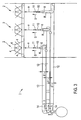
- the mixing system 1 shown in FIGS. 1 to 3 comprises a plurality of lattice-like mixing elements 2 arranged in a loading plane, of which only one mixing element 2 is shown in FIG. 1 and three mixing elements 2 are shown in FIG.
- the mixing element 2 is composed of four inclined mixing blades 4, which are arranged around a central axis 6 of the mixing element 2 around.
- the mixing vanes 4 are used to generate vortices of a flow medium S guided in a flow channel 6 arranged upstream of the mixing element 2.
- the vortices are produced by a deflection of the flow channel 6 shown in FIG. 2 in the axial direction and parallel to the flow channel Central axis 8 flowing flow medium S in the circumferential direction of the flow channel 6 and homogenize this.
- the mixing vanes 4 are arranged at a uniform angular offset from one another. In the exemplary embodiment, the angular offset is 90 °.
- the mixing vanes 4 may be inclined in particular at an angle of 15 ° to 90 °, preferably 30 ° to 60 °, to the cross-sectional plane of the flow channel 6. About this tendency, the mixing quality at a predetermined distance in the flow direction behind the mixing system 1 against the pressure loss of the flow medium S can be adjusted.
- FIG. 1 shows particularly clearly that adjacent mixing vanes 4 each have an overlap in their projection onto the normal plane of the central axis 8.
- the degree of overlap also contributes to the generation of swirl, so that the inclination of the mixing vanes 4 can be kept comparatively low, and thus the pressure loss through the mixing system 1 can be minimized even with a high mixing effect.
- the mixing vanes 4 of all mixing elements 2 can cover in their projection on the normal plane of the central axis 8 a nominal proportion of 50% to 100% of the cross-sectional area of the flow channel 6, so that a vote of the flow rate compared to the mixing quality can be made.
- an injection point 10 for a reaction medium R is arranged on the central axis 8 in the exemplary embodiment before each mixing element 2.
- the injection point 10 is designed for extensive atomization of the reaction medium R and its fine distribution in the flow medium S.
- the turbulence caused by this results in a homogenization of the entire media flow, so that a particularly intimate and uniform mixing of the flow medium S and the reaction medium R is ensured.
- the dimensions of the mixing elements 2 and the injection points 10 are mutually coordinated such that the quotient of the degree of overlapping of two adjacent mixing blades 4 (in percent) and the excess factor by which the exit velocity of the reaction medium R from the injection point 10 exceeds the velocity of the flow medium S in the flow channel 6, 0.1 to 5, in particular 0.5 to 2 , is.
- the distance a between the outlet 11 of the injection point 10 and the mixing element 2 is preferably 0.05 m to 2 m, in particular 0.2 m to 0.5 m.
- each injection point 10 is associated with a supply line 12.
- Several supply lines 12 are, as shown particularly in Fig. 3, arranged one behind the other in the flow direction. As a result, the pressure loss in the flow channel 6 is kept particularly low.
- a valve 14 is disposed on each supply line 12 of the relevant injection point 10.
- the volume flow of the reaction medium R can be metered and adjusted individually, so that the distribution profile of the reaction medium R in the flow medium S can be influenced particularly quickly and effectively.
- each supply line 12 is dimensioned such that the media speed in the supply lines 12 is 0.3 to 1 times the exit velocity at the outlet 11 of the injection point 10 in the embodiment.
Landscapes
- Chemical & Material Sciences (AREA)
- Chemical Kinetics & Catalysis (AREA)
- Engineering & Computer Science (AREA)
- Environmental & Geological Engineering (AREA)
- Health & Medical Sciences (AREA)
- Biomedical Technology (AREA)
- Analytical Chemistry (AREA)
- General Chemical & Material Sciences (AREA)
- Oil, Petroleum & Natural Gas (AREA)
- Dispersion Chemistry (AREA)
- Physical Or Chemical Processes And Apparatus (AREA)
- Mixers Of The Rotary Stirring Type (AREA)
Priority Applications (1)
| Application Number | Priority Date | Filing Date | Title |
|---|---|---|---|
| PL04739561T PL1651335T3 (pl) | 2003-07-28 | 2004-06-03 | Układ do mieszania |
Applications Claiming Priority (2)
| Application Number | Priority Date | Filing Date | Title |
|---|---|---|---|
| DE10334593A DE10334593B3 (de) | 2003-07-28 | 2003-07-28 | Mischsystem |
| PCT/EP2004/005994 WO2005021144A1 (de) | 2003-07-28 | 2004-06-03 | Mischsystem |
Publications (2)
| Publication Number | Publication Date |
|---|---|
| EP1651335A1 EP1651335A1 (de) | 2006-05-03 |
| EP1651335B1 true EP1651335B1 (de) | 2006-11-29 |
Family
ID=34258144
Family Applications (1)
| Application Number | Title | Priority Date | Filing Date |
|---|---|---|---|
| EP04739561A Expired - Lifetime EP1651335B1 (de) | 2003-07-28 | 2004-06-03 | Mischsystem |
Country Status (7)
| Country | Link |
|---|---|
| US (1) | US7665884B2 (zh) |
| EP (1) | EP1651335B1 (zh) |
| CN (1) | CN100400146C (zh) |
| AT (1) | ATE346681T1 (zh) |
| DE (2) | DE10334593B3 (zh) |
| PL (1) | PL1651335T3 (zh) |
| WO (1) | WO2005021144A1 (zh) |
Families Citing this family (13)
| Publication number | Priority date | Publication date | Assignee | Title |
|---|---|---|---|---|
| JP4770312B2 (ja) * | 2005-07-26 | 2011-09-14 | トヨタ自動車株式会社 | ガスの希釈器 |
| CN102389727B (zh) * | 2011-10-13 | 2013-10-09 | 东南大学 | 一种scr脱硝四角切圆式氨气-烟气均混装置 |
| EP2620208B1 (en) | 2012-01-25 | 2017-01-04 | General Electric Technology GmbH | Gas mixing arrangement |
| EP2623181B1 (en) * | 2012-02-03 | 2016-04-13 | Alstom Technology Ltd | Arrangement for injecting a reducing agent into a flue gas |
| CN102626585B (zh) * | 2012-04-16 | 2014-11-05 | 浙江大学 | 一种用于scr烟气脱硝装置的v型喷氨混合系统 |
| US9649604B2 (en) | 2012-05-10 | 2017-05-16 | General Electric Technology Gmbh | Injector grid with two stage mixer |
| CN103007701B (zh) * | 2012-10-16 | 2015-05-27 | 西安热工研究院有限公司 | 一种局部涡流和整体旋流相结合的花瓣型喷氨格栅 |
| CN103055734A (zh) * | 2013-01-05 | 2013-04-24 | 中国计量学院 | 半柔性柳叶型叶片scr静态混合器 |
| CN103990395B (zh) * | 2014-05-16 | 2016-04-13 | 北京博智伟德环保科技有限公司 | 一种氨气/空气混合器 |
| CN104689735B (zh) * | 2015-03-19 | 2016-08-31 | 西安西热锅炉环保工程有限公司 | 一种适用于烟道式脱硝反应器的一体式氨注射混合器 |
| EP3627051A1 (en) | 2018-09-18 | 2020-03-25 | Yara International ASA | Nox abatement system for a stationary burning system |
| CN114765964A (zh) | 2019-11-04 | 2022-07-19 | 帕克-汉尼芬公司 | 管线混合器装置、混合方法及制作管线混合器装置的方法 |
| CN111420541A (zh) * | 2020-04-29 | 2020-07-17 | 华能国际电力股份有限公司 | 一种适用于煤粉锅炉高温烟气sncr脱硝的新型混合器结构 |
Family Cites Families (16)
| Publication number | Priority date | Publication date | Assignee | Title |
|---|---|---|---|---|
| US1218250A (en) * | 1915-07-03 | 1917-03-06 | John Fox | Grain-pickler. |
| FR1372655A (fr) * | 1963-08-09 | 1964-09-18 | Synthese Et D Oxydation Synoxy | Procédé et dispositif de mélange et d'homogénéisation de fluides |
| US4068830A (en) * | 1974-01-04 | 1978-01-17 | E. I. Du Pont De Nemours And Company | Mixing method and system |
| DE3043239C2 (de) * | 1980-11-15 | 1985-11-28 | Balcke-Dürr AG, 4030 Ratingen | Verfahren und Vorrichtung zum Vermischen mindestens zweier fluider Teilströme |
| DE59206987D1 (de) * | 1991-07-30 | 1996-10-02 | Sulzer Chemtech Ag | Einmischvorrichtung |
| DE59204320D1 (de) * | 1991-07-30 | 1995-12-21 | Sulzer Chemtech Ag | Einmischvorrichtung kleiner Fluidmengen. |
| US5380008A (en) | 1993-12-03 | 1995-01-10 | Spintek International | Electronic gaming apparatus |
| DE19731926C1 (de) * | 1997-07-24 | 1999-01-21 | Siemens Ag | Abgasreinigungsanlage für einen Dieselmotor |
| US5863128A (en) * | 1997-12-04 | 1999-01-26 | Mazzei; Angelo L. | Mixer-injectors with twisting and straightening vanes |
| ATE299392T1 (de) * | 1999-04-19 | 2005-07-15 | Sulzer Chemtech Ag | Statischer wirbelmischer und methode zur verwendung desselben |
| DE19934413A1 (de) * | 1999-07-22 | 2001-01-25 | Siemens Ag | Vorrichtung zum Einbringen eines Zuschlagstoffes in ein Abgas |
| US6331317B1 (en) * | 1999-11-12 | 2001-12-18 | Alkermes Controlled Therapeutics Ii Inc. | Apparatus and method for preparing microparticles |
| DE10005457A1 (de) * | 2000-02-08 | 2001-08-09 | Bayer Ag | Statischer Mischer |
| ATE402908T1 (de) * | 2000-06-06 | 2008-08-15 | Trojan Techn Inc | Mischvorrichtung für fluide |
| US6886973B2 (en) * | 2001-01-03 | 2005-05-03 | Basic Resources, Inc. | Gas stream vortex mixing system |
| US7503686B2 (en) * | 2006-07-11 | 2009-03-17 | Paradox Holding Company, Llc | Apparatus and method for mixing fluids at the surface for subterranean treatments |
-
2003
- 2003-07-28 DE DE10334593A patent/DE10334593B3/de not_active Expired - Fee Related
-
2004
- 2004-06-03 WO PCT/EP2004/005994 patent/WO2005021144A1/de active IP Right Grant
- 2004-06-03 CN CNB2004800217516A patent/CN100400146C/zh not_active Expired - Lifetime
- 2004-06-03 DE DE502004002205T patent/DE502004002205D1/de not_active Expired - Lifetime
- 2004-06-03 PL PL04739561T patent/PL1651335T3/pl unknown
- 2004-06-03 AT AT04739561T patent/ATE346681T1/de active
- 2004-06-03 EP EP04739561A patent/EP1651335B1/de not_active Expired - Lifetime
-
2006
- 2006-01-30 US US11/343,153 patent/US7665884B2/en not_active Expired - Fee Related
Also Published As
| Publication number | Publication date |
|---|---|
| EP1651335A1 (de) | 2006-05-03 |
| US7665884B2 (en) | 2010-02-23 |
| CN100400146C (zh) | 2008-07-09 |
| ATE346681T1 (de) | 2006-12-15 |
| WO2005021144A1 (de) | 2005-03-10 |
| DE10334593B3 (de) | 2005-04-21 |
| US20060176764A1 (en) | 2006-08-10 |
| CN1829565A (zh) | 2006-09-06 |
| PL1651335T3 (pl) | 2007-06-29 |
| DE502004002205D1 (de) | 2007-01-11 |
Similar Documents
| Publication | Publication Date | Title |
|---|---|---|
| EP0526393B1 (de) | Einmischvorrichtung | |
| EP0637726B1 (de) | Vorrichtung zum Kühlen von Gasen und ggf. Trocknen von dem Gas zugegebenen Feststoffteilchen | |
| EP1651335B1 (de) | Mischsystem | |
| EP1681090B1 (de) | Vorrichtung und Verfahren zum Mischen eines Fluidstroms in einem Strömungskanal | |
| DE102020124106A1 (de) | Kraftfahrzeugabgasnachbehandlungssystem | |
| DE102010021438B4 (de) | Abgasnachbehandlungsvorrichtung | |
| DE102006058715B3 (de) | Statischer Mischer für eine Abgasanlage eines brennkraftmaschinenbetriebenen Fahrzeugs, insbesondere Kraftfahrzeugs | |
| EP2985434B1 (de) | Abgasreinigungsvorrichtung für ein fahrzeug, insbesondere für ein nutzfahrzeug | |
| EP1166861B1 (de) | Mischer für die Mischung mindestens zweier Gasströme oder anderer Newtonscher Flüssigkeiten | |
| DE112017007996T5 (de) | Einspritzdüsenkegel nach Art einer Venturidüse | |
| EP2687697A2 (de) | Mischvorrichtung zur Nachbehandlung von Abgasen | |
| EP0526392A1 (de) | Einmischvorrichtung kleiner Fluidmengen | |
| EP2570178B1 (de) | Mischeinrichtung | |
| DE202021104734U1 (de) | Mischer und Abgassystem mit solchem Mischer | |
| DE102022112337A1 (de) | Mischerbaugruppe für ein fahrzeugabgassystem | |
| DE102008053669A1 (de) | Abgasanlage für ein Fahrzeug | |
| EP0751820B1 (de) | Kombinierte einbring- und mischvorrichtung | |
| WO2017137032A1 (de) | Mischer zum durchmischen eines abgasstroms einer brennkraftmaschine und abgasanlage | |
| DE112017005323T5 (de) | Substratform, Geometrie, Positionierung und/oder Zelldichte zur Verbesserung der Nachbehandlungsleistung | |
| DE102006059761A1 (de) | Abgasrohr für eine Abgasanlage einer Verbrennungskraftmaschine | |
| DE102022121551A1 (de) | Mischer, Mischerbaugruppe und Mischverfahren | |
| EP3050615A1 (de) | Strömungseinheit, Abgasreinigungsanlage und Verfahren für eine Abgasreinigungsanlage | |
| DE10324886B4 (de) | Mischelement und statischer Mischer mit einer Anzahl derartiger Mischelemente | |
| EP3645149B1 (de) | Verteiler für ein fluid | |
| WO2015185297A1 (de) | Einspritzmodul und abgasstrang mit einspritzmodul |
Legal Events
| Date | Code | Title | Description |
|---|---|---|---|
| PUAI | Public reference made under article 153(3) epc to a published international application that has entered the european phase |
Free format text: ORIGINAL CODE: 0009012 |
|
| 17P | Request for examination filed |
Effective date: 20060228 |
|
| AK | Designated contracting states |
Kind code of ref document: A1 Designated state(s): AT BE BG CH CY CZ DE DK EE ES FI FR GB GR HU IE IT LI LU MC NL PL PT RO SE SI SK TR |
|
| GRAP | Despatch of communication of intention to grant a patent |
Free format text: ORIGINAL CODE: EPIDOSNIGR1 |
|
| RIN1 | Information on inventor provided before grant (corrected) |
Inventor name: WALTER, DIRK Inventor name: WEIGL, KLAUS Inventor name: BUDIN, RICHARD Inventor name: GANZMANN, INGO |
|
| GRAS | Grant fee paid |
Free format text: ORIGINAL CODE: EPIDOSNIGR3 |
|
| GRAA | (expected) grant |
Free format text: ORIGINAL CODE: 0009210 |
|
| DAX | Request for extension of the european patent (deleted) | ||
| AK | Designated contracting states |
Kind code of ref document: B1 Designated state(s): AT BE BG CH CY CZ DE DK EE ES FI FR GB GR HU IE IT LI LU MC NL PL PT RO SE SI SK TR |
|
| PG25 | Lapsed in a contracting state [announced via postgrant information from national office to epo] |
Ref country code: FI Free format text: LAPSE BECAUSE OF FAILURE TO SUBMIT A TRANSLATION OF THE DESCRIPTION OR TO PAY THE FEE WITHIN THE PRESCRIBED TIME-LIMIT Effective date: 20061129 Ref country code: IE Free format text: LAPSE BECAUSE OF FAILURE TO SUBMIT A TRANSLATION OF THE DESCRIPTION OR TO PAY THE FEE WITHIN THE PRESCRIBED TIME-LIMIT Effective date: 20061129 Ref country code: SI Free format text: LAPSE BECAUSE OF FAILURE TO SUBMIT A TRANSLATION OF THE DESCRIPTION OR TO PAY THE FEE WITHIN THE PRESCRIBED TIME-LIMIT Effective date: 20061129 Ref country code: RO Free format text: LAPSE BECAUSE OF FAILURE TO SUBMIT A TRANSLATION OF THE DESCRIPTION OR TO PAY THE FEE WITHIN THE PRESCRIBED TIME-LIMIT Effective date: 20061129 |
|
| REG | Reference to a national code |
Ref country code: GB Ref legal event code: FG4D Free format text: NOT ENGLISH |
|
| REG | Reference to a national code |
Ref country code: CH Ref legal event code: EP |
|
| REG | Reference to a national code |
Ref country code: IE Ref legal event code: FG4D Free format text: LANGUAGE OF EP DOCUMENT: GERMAN |
|
| REF | Corresponds to: |
Ref document number: 502004002205 Country of ref document: DE Date of ref document: 20070111 Kind code of ref document: P |
|
| PG25 | Lapsed in a contracting state [announced via postgrant information from national office to epo] |
Ref country code: SE Free format text: LAPSE BECAUSE OF FAILURE TO SUBMIT A TRANSLATION OF THE DESCRIPTION OR TO PAY THE FEE WITHIN THE PRESCRIBED TIME-LIMIT Effective date: 20070228 Ref country code: DK Free format text: LAPSE BECAUSE OF FAILURE TO SUBMIT A TRANSLATION OF THE DESCRIPTION OR TO PAY THE FEE WITHIN THE PRESCRIBED TIME-LIMIT Effective date: 20070228 Ref country code: BG Free format text: LAPSE BECAUSE OF FAILURE TO SUBMIT A TRANSLATION OF THE DESCRIPTION OR TO PAY THE FEE WITHIN THE PRESCRIBED TIME-LIMIT Effective date: 20070228 |
|
| PG25 | Lapsed in a contracting state [announced via postgrant information from national office to epo] |
Ref country code: ES Free format text: LAPSE BECAUSE OF FAILURE TO SUBMIT A TRANSLATION OF THE DESCRIPTION OR TO PAY THE FEE WITHIN THE PRESCRIBED TIME-LIMIT Effective date: 20070312 |
|
| PG25 | Lapsed in a contracting state [announced via postgrant information from national office to epo] |
Ref country code: PT Free format text: LAPSE BECAUSE OF FAILURE TO SUBMIT A TRANSLATION OF THE DESCRIPTION OR TO PAY THE FEE WITHIN THE PRESCRIBED TIME-LIMIT Effective date: 20070430 |
|
| ET | Fr: translation filed | ||
| GBV | Gb: ep patent (uk) treated as always having been void in accordance with gb section 77(7)/1977 [no translation filed] |
Effective date: 20061129 |
|
| REG | Reference to a national code |
Ref country code: IE Ref legal event code: FD4D |
|
| REG | Reference to a national code |
Ref country code: PL Ref legal event code: T3 |
|
| PLBE | No opposition filed within time limit |
Free format text: ORIGINAL CODE: 0009261 |
|
| STAA | Information on the status of an ep patent application or granted ep patent |
Free format text: STATUS: NO OPPOSITION FILED WITHIN TIME LIMIT |
|
| 26N | No opposition filed |
Effective date: 20070830 |
|
| PG25 | Lapsed in a contracting state [announced via postgrant information from national office to epo] |
Ref country code: GB Free format text: LAPSE BECAUSE OF FAILURE TO SUBMIT A TRANSLATION OF THE DESCRIPTION OR TO PAY THE FEE WITHIN THE PRESCRIBED TIME-LIMIT Effective date: 20061129 |
|
| PG25 | Lapsed in a contracting state [announced via postgrant information from national office to epo] |
Ref country code: MC Free format text: LAPSE BECAUSE OF NON-PAYMENT OF DUE FEES Effective date: 20070630 |
|
| PG25 | Lapsed in a contracting state [announced via postgrant information from national office to epo] |
Ref country code: GR Free format text: LAPSE BECAUSE OF FAILURE TO SUBMIT A TRANSLATION OF THE DESCRIPTION OR TO PAY THE FEE WITHIN THE PRESCRIBED TIME-LIMIT Effective date: 20070301 |
|
| NLT1 | Nl: modifications of names registered in virtue of documents presented to the patent office pursuant to art. 16 a, paragraph 1 |
Owner name: ENVIRGY ENVIRONMENT ENERGY ENGINEERING CONSTRUCTIO Owner name: AREVA NP GMBH |
|
| PG25 | Lapsed in a contracting state [announced via postgrant information from national office to epo] |
Ref country code: EE Free format text: LAPSE BECAUSE OF FAILURE TO SUBMIT A TRANSLATION OF THE DESCRIPTION OR TO PAY THE FEE WITHIN THE PRESCRIBED TIME-LIMIT Effective date: 20061129 |
|
| REG | Reference to a national code |
Ref country code: CH Ref legal event code: PL |
|
| PG25 | Lapsed in a contracting state [announced via postgrant information from national office to epo] |
Ref country code: LI Free format text: LAPSE BECAUSE OF NON-PAYMENT OF DUE FEES Effective date: 20080630 Ref country code: CH Free format text: LAPSE BECAUSE OF NON-PAYMENT OF DUE FEES Effective date: 20080630 |
|
| PG25 | Lapsed in a contracting state [announced via postgrant information from national office to epo] |
Ref country code: LU Free format text: LAPSE BECAUSE OF NON-PAYMENT OF DUE FEES Effective date: 20070603 Ref country code: CY Free format text: LAPSE BECAUSE OF FAILURE TO SUBMIT A TRANSLATION OF THE DESCRIPTION OR TO PAY THE FEE WITHIN THE PRESCRIBED TIME-LIMIT Effective date: 20061129 |
|
| PG25 | Lapsed in a contracting state [announced via postgrant information from national office to epo] |
Ref country code: HU Free format text: LAPSE BECAUSE OF FAILURE TO SUBMIT A TRANSLATION OF THE DESCRIPTION OR TO PAY THE FEE WITHIN THE PRESCRIBED TIME-LIMIT Effective date: 20070530 Ref country code: TR Free format text: LAPSE BECAUSE OF FAILURE TO SUBMIT A TRANSLATION OF THE DESCRIPTION OR TO PAY THE FEE WITHIN THE PRESCRIBED TIME-LIMIT Effective date: 20061129 |
|
| BECA | Be: change of holder's address |
Owner name: PAUL-GOSSEN-STRASSE 100, D-91058 ERLANGEN (DE) Effective date: 20091127 Owner name: AREVA NP G.M.B.H.WIENERBERGSTRASSE 11/A8, AT-1100 Effective date: 20091127 Owner name: STRABAG A.G., ENVIRONMENTAL TECHNILOGY, BUSINESS U Effective date: 20091127 |
|
| BECH | Be: change of holder |
Owner name: AREVA NP G.M.B.H. Effective date: 20091127 Owner name: STRABAG A.G., ENVIRONMENTAL TECHNILOGY, BUSINESS U Effective date: 20091127 |
|
| REG | Reference to a national code |
Ref country code: FR Ref legal event code: TQ |
|
| NLS | Nl: assignments of ep-patents |
Owner name: STARBAG AG, ENVIROMENTAL TECHNOLOGY, BUSINESS UNIT Effective date: 20100211 Owner name: AREVA NP GMBH Effective date: 20100211 |
|
| REG | Reference to a national code |
Ref country code: FR Ref legal event code: CD Ref country code: FR Ref legal event code: CA |
|
| REG | Reference to a national code |
Ref country code: SK Ref legal event code: PC4A Ref document number: E 2300 Country of ref document: SK Owner name: AREVA NP GMBH, ERLANGEN, DE Free format text: FORMER OWNER: AREVA NP GMBH, ERLANGEN, DE; ENVIRGY ENVIRONMENT ENERGY ENGINEERING CONSTRUCTION GMBH, WIEN, AT Effective date: 20101004 Ref country code: SK Ref legal event code: PC4A Ref document number: E 2300 Country of ref document: SK Owner name: STRABAG AG, ENVIRONMENTAL TECHNOLOGY, BUSINESS, AT Free format text: FORMER OWNER: AREVA NP GMBH, ERLANGEN, DE; ENVIRGY ENVIRONMENT ENERGY ENGINEERING CONSTRUCTION GMBH, WIEN, AT Effective date: 20101004 |
|
| REG | Reference to a national code |
Ref country code: DE Ref legal event code: R082 Ref document number: 502004002205 Country of ref document: DE Representative=s name: TERGAU & WALKENHORST PATENTANWAELTE - RECHTSAN, DE |
|
| REG | Reference to a national code |
Ref country code: DE Ref legal event code: R081 Ref document number: 502004002205 Country of ref document: DE Owner name: STRABAG AG, AT Free format text: FORMER OWNERS: AREVA NP GMBH, 91052 ERLANGEN, DE; STRABAG AG, WIEN, AT Effective date: 20130523 Ref country code: DE Ref legal event code: R081 Ref document number: 502004002205 Country of ref document: DE Owner name: AREVA GMBH, DE Free format text: FORMER OWNERS: AREVA NP GMBH, 91052 ERLANGEN, DE; STRABAG AG, WIEN, AT Effective date: 20130523 Ref country code: DE Ref legal event code: R082 Ref document number: 502004002205 Country of ref document: DE Representative=s name: TERGAU & WALKENHORST PATENTANWAELTE PARTGMBB, DE Effective date: 20130523 Ref country code: DE Ref legal event code: R081 Ref document number: 502004002205 Country of ref document: DE Owner name: YARA ENVIRONMENTAL TECHNOLOGIES GMBH, AT Free format text: FORMER OWNERS: AREVA NP GMBH, 91052 ERLANGEN, DE; STRABAG AG, WIEN, AT Effective date: 20130523 Ref country code: DE Ref legal event code: R082 Ref document number: 502004002205 Country of ref document: DE Representative=s name: WEICKMANN & WEICKMANN PATENTANWAELTE - RECHTSA, DE Effective date: 20130523 Ref country code: DE Ref legal event code: R082 Ref document number: 502004002205 Country of ref document: DE Representative=s name: WEICKMANN & WEICKMANN PATENT- UND RECHTSANWAEL, DE Effective date: 20130523 Ref country code: DE Ref legal event code: R081 Ref document number: 502004002205 Country of ref document: DE Owner name: AREVA GMBH, DE Free format text: FORMER OWNER: AREVA NP GMBH, STRABAG AG, , AT Effective date: 20130523 Ref country code: DE Ref legal event code: R081 Ref document number: 502004002205 Country of ref document: DE Owner name: STRABAG AG, AT Free format text: FORMER OWNER: AREVA NP GMBH, STRABAG AG, , AT Effective date: 20130523 Ref country code: DE Ref legal event code: R082 Ref document number: 502004002205 Country of ref document: DE Representative=s name: TERGAU & WALKENHORST PATENTANWAELTE - RECHTSAN, DE Effective date: 20130523 |
|
| REG | Reference to a national code |
Ref country code: DE Ref legal event code: R082 Ref document number: 502004002205 Country of ref document: DE Representative=s name: WEICKMANN & WEICKMANN PATENTANWAELTE - RECHTSA, DE Ref country code: DE Ref legal event code: R081 Ref document number: 502004002205 Country of ref document: DE Owner name: YARA ENVIRONMENTAL TECHNOLOGIES GMBH, AT Free format text: FORMER OWNERS: AREVA GMBH, 91052 ERLANGEN, DE; STRABAG AG, WIEN, AT Ref country code: DE Ref legal event code: R082 Ref document number: 502004002205 Country of ref document: DE Representative=s name: WEICKMANN & WEICKMANN PATENT- UND RECHTSANWAEL, DE |
|
| REG | Reference to a national code |
Ref country code: SK Ref legal event code: PC4A Ref document number: E 2300 Country of ref document: SK Owner name: YARA ENVIRONMENTAL TECHNOLOGIES GMBH, VIENNA, AT Free format text: FORMER OWNER: STRABAG AG, ENVIRONMENTAL TECHNOLOGY, BUSINESS UNIT FLUE GAS TREATMENT, WIEN, AT; AREVA NP GMBH, ERLANGEN, DE Effective date: 20160311 |
|
| REG | Reference to a national code |
Ref country code: NL Ref legal event code: PD Owner name: YARA ENVIRONMENTAL TECHNOLOGIES GMBH; AT Free format text: DETAILS ASSIGNMENT: VERANDERING VAN EIGENAAR(S), OVERDRACHT; FORMER OWNER NAME: ENVIROMENTAL TECHNOLOGY, ATMENT STRABAG AG, ENVIRONMENTAL TECHNOLOGY, BUSINESS UNIT FLUE GAS TREATMENT Effective date: 20151117 |
|
| REG | Reference to a national code |
Ref country code: FR Ref legal event code: PLFP Year of fee payment: 13 |
|
| REG | Reference to a national code |
Ref country code: AT Ref legal event code: PC Ref document number: 346681 Country of ref document: AT Kind code of ref document: T Owner name: YARA ENVIRONMETAL TECHNOLOGIES GMBH, AT Effective date: 20160713 |
|
| REG | Reference to a national code |
Ref country code: FR Ref legal event code: TP Owner name: YARA ENVIRONMENTAL TECHNOLOGIES GMBH, AU Effective date: 20160927 |
|
| REG | Reference to a national code |
Ref country code: FR Ref legal event code: PLFP Year of fee payment: 14 |
|
| REG | Reference to a national code |
Ref country code: FR Ref legal event code: PLFP Year of fee payment: 15 |
|
| REG | Reference to a national code |
Ref country code: DE Ref legal event code: R079 Ref document number: 502004002205 Country of ref document: DE Free format text: PREVIOUS MAIN CLASS: B01F0005040000 Ipc: B01F0025300000 |
|
| REG | Reference to a national code |
Ref country code: FR Ref legal event code: PLFP Year of fee payment: 20 |
|
| PGFP | Annual fee paid to national office [announced via postgrant information from national office to epo] |
Ref country code: PL Payment date: 20230315 Year of fee payment: 20 |
|
| PGFP | Annual fee paid to national office [announced via postgrant information from national office to epo] |
Ref country code: NL Payment date: 20230417 Year of fee payment: 20 |
|
| PGFP | Annual fee paid to national office [announced via postgrant information from national office to epo] |
Ref country code: IT Payment date: 20230510 Year of fee payment: 20 Ref country code: FR Payment date: 20230411 Year of fee payment: 20 Ref country code: DE Payment date: 20230412 Year of fee payment: 20 Ref country code: CZ Payment date: 20230517 Year of fee payment: 20 |
|
| PGFP | Annual fee paid to national office [announced via postgrant information from national office to epo] |
Ref country code: SK Payment date: 20230425 Year of fee payment: 20 Ref country code: AT Payment date: 20230525 Year of fee payment: 20 |
|
| PGFP | Annual fee paid to national office [announced via postgrant information from national office to epo] |
Ref country code: BE Payment date: 20230517 Year of fee payment: 20 |
|
| REG | Reference to a national code |
Ref country code: DE Ref legal event code: R071 Ref document number: 502004002205 Country of ref document: DE |
|
| REG | Reference to a national code |
Ref country code: NL Ref legal event code: MK Effective date: 20240602 |
|
| REG | Reference to a national code |
Ref country code: BE Ref legal event code: MK Effective date: 20240603 |
|
| REG | Reference to a national code |
Ref country code: SK Ref legal event code: MK4A Ref document number: E 2300 Country of ref document: SK Expiry date: 20240603 |
|
| REG | Reference to a national code |
Ref country code: AT Ref legal event code: MK07 Ref document number: 346681 Country of ref document: AT Kind code of ref document: T Effective date: 20240603 |
|
| PG25 | Lapsed in a contracting state [announced via postgrant information from national office to epo] |
Ref country code: CZ Free format text: LAPSE BECAUSE OF EXPIRATION OF PROTECTION Effective date: 20240603 |
|
| PG25 | Lapsed in a contracting state [announced via postgrant information from national office to epo] |
Ref country code: SK Free format text: LAPSE BECAUSE OF EXPIRATION OF PROTECTION Effective date: 20240603 |
|
| PG25 | Lapsed in a contracting state [announced via postgrant information from national office to epo] |
Ref country code: SK Free format text: LAPSE BECAUSE OF EXPIRATION OF PROTECTION Effective date: 20240603 Ref country code: CZ Free format text: LAPSE BECAUSE OF EXPIRATION OF PROTECTION Effective date: 20240603 |