EP1650764A1 - Cartouche de disque - Google Patents
Cartouche de disque Download PDFInfo
- Publication number
- EP1650764A1 EP1650764A1 EP04770908A EP04770908A EP1650764A1 EP 1650764 A1 EP1650764 A1 EP 1650764A1 EP 04770908 A EP04770908 A EP 04770908A EP 04770908 A EP04770908 A EP 04770908A EP 1650764 A1 EP1650764 A1 EP 1650764A1
- Authority
- EP
- European Patent Office
- Prior art keywords
- disc
- body unit
- cartridge
- recording
- unit
- Prior art date
- Legal status (The legal status is an assumption and is not a legal conclusion. Google has not performed a legal analysis and makes no representation as to the accuracy of the status listed.)
- Granted
Links
- 230000003287 optical effect Effects 0.000 abstract description 72
- 238000003780 insertion Methods 0.000 abstract description 17
- 230000037431 insertion Effects 0.000 abstract description 17
- 230000002829 reductive effect Effects 0.000 description 15
- 230000014759 maintenance of location Effects 0.000 description 13
- 230000013011 mating Effects 0.000 description 12
- 230000002093 peripheral effect Effects 0.000 description 5
- 230000002401 inhibitory effect Effects 0.000 description 3
- 230000000717 retained effect Effects 0.000 description 3
- 238000003466 welding Methods 0.000 description 3
- 239000000463 material Substances 0.000 description 2
- 238000000034 method Methods 0.000 description 2
- 229920003002 synthetic resin Polymers 0.000 description 2
- 239000000057 synthetic resin Substances 0.000 description 2
- 239000004973 liquid crystal related substance Substances 0.000 description 1
- 239000002184 metal Substances 0.000 description 1
- 238000012986 modification Methods 0.000 description 1
- 230000004048 modification Effects 0.000 description 1
- 238000003825 pressing Methods 0.000 description 1
- 238000004080 punching Methods 0.000 description 1
- 230000002441 reversible effect Effects 0.000 description 1
- 238000007493 shaping process Methods 0.000 description 1
- 238000005549 size reduction Methods 0.000 description 1
- 230000005236 sound signal Effects 0.000 description 1
- 238000006467 substitution reaction Methods 0.000 description 1
- 230000000007 visual effect Effects 0.000 description 1
Images


Classifications
-
- G—PHYSICS
- G11—INFORMATION STORAGE
- G11B—INFORMATION STORAGE BASED ON RELATIVE MOVEMENT BETWEEN RECORD CARRIER AND TRANSDUCER
- G11B23/00—Record carriers not specific to the method of recording or reproducing; Accessories, e.g. containers, specially adapted for co-operation with the recording or reproducing apparatus ; Intermediate mediums; Apparatus or processes specially adapted for their manufacture
- G11B23/02—Containers; Storing means both adapted to cooperate with the recording or reproducing means
- G11B23/03—Containers for flat record carriers
- G11B23/0301—Details
- G11B23/0313—Container cases
- G11B23/0316—Constructional details, e.g. shape
-
- G—PHYSICS
- G11—INFORMATION STORAGE
- G11B—INFORMATION STORAGE BASED ON RELATIVE MOVEMENT BETWEEN RECORD CARRIER AND TRANSDUCER
- G11B23/00—Record carriers not specific to the method of recording or reproducing; Accessories, e.g. containers, specially adapted for co-operation with the recording or reproducing apparatus ; Intermediate mediums; Apparatus or processes specially adapted for their manufacture
- G11B23/02—Containers; Storing means both adapted to cooperate with the recording or reproducing means
- G11B23/03—Containers for flat record carriers
- G11B23/0301—Details
- G11B23/0307—Positioning or centering features
-
- G—PHYSICS
- G11—INFORMATION STORAGE
- G11B—INFORMATION STORAGE BASED ON RELATIVE MOVEMENT BETWEEN RECORD CARRIER AND TRANSDUCER
- G11B23/00—Record carriers not specific to the method of recording or reproducing; Accessories, e.g. containers, specially adapted for co-operation with the recording or reproducing apparatus ; Intermediate mediums; Apparatus or processes specially adapted for their manufacture
- G11B23/02—Containers; Storing means both adapted to cooperate with the recording or reproducing means
- G11B23/03—Containers for flat record carriers
- G11B23/0301—Details
- G11B23/0308—Shutters
Definitions
- This invention relates to a disc cartridge, having a disc-shaped recording medium, such as an optical disc, held therein.
- a disc cartridge having a disc-shaped recording medium, such as an optical disc, rotatably housed therein, and which is loaded on a disc recording and/or reproducing apparatus, is housed therein as a disc-shaped recording medium, has been in use extensively.
- This sort of the disc cartridge comprising a disc-shaped recording medium, housed in a main cartridge body unit, can be loaded/ unloaded for the disc recording and/or reproducing apparatus, with the disc-shaped recording medium in a protected state.
- disc-shaped recording mediums housed in disc cartridges
- the disc-shaped recording mediums, different in the recording and/or reproducing system may not be recorded and/or reproduced on a common recording and/or reproducing apparatus with compatibility.
- the disc cartridge, housing a disc-shaped recording medium, substantially common in size also has a outer substantially common outer shape. That is, a disc cartridge substantially common in outer shape but different in the recording and/or reproducing system is now presented to the market.
- these commercially available disc cartridges there are those having discriminating parts for discriminating the sort of the disc-shaped recording mediums housed therein. These discriminating parts are mechanically or electrically discernible, using a cartridge discriminating unit provided to the recording and/or reproducing apparatus carrying the disc cartridge, but are difficult to discern readily on visual observation.
- the inserting end into the recording and/or reproducing apparatus has a substantially arcuate lateral side as an inserting end to the recording and/or reproducing apparatus, so that the inserting direction into the recording and/or reproducing apparatus may readily be identified, while the mistaken insertion into the recording and/or reproducing apparatus may readily be prevented from occurring.
- the lateral side is arcuate-shaped, the disc cartridge may be smaller in size than a rectangular-shaped disc cartridge.
- the lateral side of the main cartridge body unit is arcuately-shaped.
- the disc cartridge is not reduced in size in keeping with the disc-shaped recording medium housed therein.
- the rectangular-shaped disc cartridge may be inserted into or detached from a cartridge supporting part of a cartridge holder provided to the recording and/or reproducing apparatus. That is, the rectangular-shaped disc cartridge may be loaded or unloaded in stability by causing its movement along an inserting guide part provided to the recording and/or reproducing apparatus.
- an engagement recess engaged by a mating engagement portion of the ejection unit provided to the recording and/or reproducing apparatus, it is naturally provided in a flat surface parallel to the inserting direction.
- the inserting end of a disc cartridge into the recording and/or reproducing apparatus is arcuately-shaped, as in the disc cartridge shown in the Patent publication 1, for reducing the size of the disc cartridge in keeping with the disc-shaped recording medium accommodated therein, it may be difficult to provide the engagement recess, engaged by a mating engagement portion of the ejection unit provided to the recording and/or reproducing apparatus, in a flat surface extending parallel to the inserting direction. That is, the engagement recess, which enables an ejection unit to be operated in stability during the operation of inserting the disc cartridge into the recording and/or reproducing apparatus, it may become impossible to provide the recess in the flat surface extending parallel to the inserting direction, as a result of the attempt to reduce the size of the disc cartridge.
- the present invention provides a disc cartridge comprising a disc, and a main cartridge body unit having the disc rotatably housed therein, in which one lateral surface of the main cartridge body unit is a substantially semicircular arcuate section having the center of the disc housed in the main cartridge body unit as center.
- one lateral surface of the main cartridge body unit is formed as a substantially semicircular arcuate section having the center of the disc accommodated in the main cartridge body unit as a center, so that at least one lateral side of the disc cartridge is of a size substantially proximate to the semicircle of the disc accommodated therein, thus achieving further size reduction of the main cartridge body unit.
- the arcuate section provided to the main cartridge body unit is formed on an inserting side of the main cartridge body unit into a recording and/or reproducing apparatus. Moreover, the back side of the main cartridge body unit opposite to the inserting end thereof formed as the arcuate section is a curved section having a curvature larger than that of the arcuate section.
- this disc cartridge in which the inserting end thereof into the recording and/or reproducing apparatus is formed as a substantially arcuate section, the direction of insertion into the recording and/or reproducing apparatus may be discerned readily, thereby positively prohibiting mistaken insertion.
- the inserting end of the disc cartridge according to the present invention is formed as a semicircular arcuate section, the disc cartridge may be smoothly inserted over a wide angular extent into the cartridge loading/unloading opening provided to the recording and/or reproducing apparatus.
- the main cartridge body unit includes a recording and/or reproducing aperture for exposing at least a portion of the signal recording area of the disc to outside across the inner and outer rims of the disc.
- the recording and/or reproducing aperture is formed for being opened in a lateral side of the main cartridge body unit other than the lateral side formed as the arcuate section.
- a shutter unit for opening/closing the recording and/or reproducing aperture is movably mounted to the main cartridge body unit. The shutter unit is moved along a lateral side of the main cartridge body unit other than the arcuate section of the main cartridge body unit for opening/ closing the recording and/or reproducing aperture.
- the lateral side along which is moved the shutter unit is preferably a side parallel to the movement direction of the shutter unit.
- the recording and/or reproducing aperture is formed facing the lateral surface of the main cartridge body unit other than the arcuate section thereof and hence the shutter member for opening/closing the recording and/or reproducing aperture may be movably mounted in stability to the main cartridge body unit for positively closing the recording and/or reproducing aperture.
- the disc cartridge of the present invention includes a disc, and a main cartridge body unit having the disc rotatably housed therein, in which one lateral surface of the main cartridge body unit is a substantially semicircular arcuate section having the center of the disc housed in the main cartridge body unit as center.
- An engagement recess engaged by a part of an ejection unit provided to the recording and/or reproducing apparatus loaded with the disc cartridge is formed in the lateral side of the main cartridge body unit carrying the arcuate section.
- a cut-out opened in an opposite direction to the inserting direction is formed on a side of the engagement recess opposite to the inserting direction into the recording and/or reproducing apparatus.
- Another engagement recess is formed in a lateral side of the main cartridge body unit carrying the engagement recess.
- a recording and/or reproducing aperture for exposing at least a portion of the disc is formed in the main cartridge body unit and the recording and/or reproducing aperture is formed for being opened in a lateral surface of the main cartridge body unit, formed with the engagement recess, other than the lateral side carrying the arcuate section of the main cartridge body unit.
- the shutter unit for opening/closing the recording and/or reproducing aperture is movably mounted to the main cartridge body unit.
- a part of the ejection unit When the disc cartridge of the present invention is loaded on the recording and/or reproducing apparatus, a part of the ejection unit is engaged in the engagement recess.
- a part of the ejection unit may be engaged in the cut-out provided in the side of the engagement recess opposite to the inserting direction into the recording and/or reproducing apparatus for being opened in an opposite direction to the inserting direction and hence may be engaged in the arcuately-shaped engagement recess.
- the part of the ejection unit may be positively engaged with the engagement recess even in case the disc cartridge is inserted at an inclination relative to the recording and/or reproducing apparatus.
- the loading operation may be achieved by engaging the loading unit in the other engagement recess as the orientation control means is engaged in the other engagement recess for orientation control.
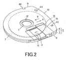
- a disc cartridge 1 houses therein an optical disc 2, as a disc-shaped recording medium, for rotation therein, and includes a main cartridge body unit 4, made up by upper and lower cartridge halves 3, 4, abutted and bonded together, as shown in Figs.1 and 2.
- the optical disc 2 is rotatably housed within this main cartridge body unit 4.
- the disc cartridge 1 houses therein the optical disc 2, on which there are recorded program data or video data for executing e.g. a television game, and is of an extremely small size.
- the present disc cartridge 1 houses therein a small-sized optical disc 2 with a diameter on the order of, for example, 60 mm, and is of a size that can be held in a user's palm.
- the optical disc 2, housed in the present disc cartridge 1 is a replay-only disc, having information signals, such as program data, pre-recorded thereon.
- the upper and lower cartridge halves 3, 4, making up a main body unit 5, housing the disc cartridge 1, is molded from a synthetic resin material, and upstanding peripheral wall sections 3a, 4a are formed on the outer rim of the halves 3a, 4a, respectively.
- the upper and lower cartridge halves 3, 4 are bonded together, with the peripheral wall sections 3a, 4a abutting to each other, thereby forming a main cartridge body unit 5 delimiting a disc housing section 6 therein.
- the upper and lower cartridge halves 3, 4 are bonded to each other to form the main cartridge body unit 5, applying a welding technique, such as an ultrasonic welding technique, to welding projections formed upright on the sides of the upper and lower cartridge halves 3, 4 facing each other.
- the main cartridge body unit 5, forming the disc cartridge 1 according to the present invention has its front side, as an inserting side end of the disc cartridge 1 into the disc recording and/or reproducing apparatus, formed as an arcuate section 7, as shown in Figs.1 to 3.
- This arcuate section 7 is formed to a semicircle of the optical disc 2 of a radius R1 housed within the disc housing section 6 of the main cartridge body unit 5, with the center of the disc as a center P0 of the semicircle, as shown in Fig.3. That is, the arcuate section 7 is formed as a semicircle commensurate with the semicircle of the optical disc 2 housed within the main cartridge body unit 5.
- the facing lateral sides of the main cartridge body unit 5, consecutive to the arcuate section 7 of the main cartridge body unit 5, are formed as sides 8, 9 parallel to each other, while the back side of the main cartridge body unit 5, lying opposite to the arcuate section 7, is formed as a uniformly smoothly curved section 10. That is, the arcuate section 7 is formed as a semicircle substantially in register with the semicircle of the optical disc 2 housed in the main cartridge body unit 5.
- the front side thereof is a substantially semicircular arcuate section 7 of a curvature larger than the other side, opposite thereto, so that, when the disc cartridge is inserted in the slot-in style via cartridge insertion/ ejection opening, the direction of insertion into the disc recording and/or reproducing apparatus can be identified extremely readily.
- the direction of insertion can be identified by the sensual touch feeling, thus prohibiting mistaken insertion to enable correct loading on the disc recording and/or reproducing apparatus.
- insertion into a slot-in type disc recording and/or reproducing apparatus may be facilitated, while positive insertion may be assured.
- the disc cartridge 1 may be further reduced in size, as compared to the optical disc 2, accommodated therein, by having the inserting end side formed as a substantially semicircular arcuate section 7, and by having the back side opposite to the arcuate section 7 similarly formed as a curved section 10.
- a circular center opening 12 for exposing a center hole 11 of the optical disc 2 housed in the main cartridge body unit 5 and the ambient part thereof to outside, as shown in Figs.2 and 3.
- a mating engagement portion such as a turntable, of a disc rotating driving mechanism, provided to the disc recording and/or reproducing apparatus on which the disc cartridge 1 is loaded.
- an aperture for the head part 13 operating as a recording/ reproducing aperture.
- the aperture for the head part 13 is provided to the lateral side 8 of the main cartridge body unit 5, and is formed as a rectangular aperture sized so as to be large enough to permit a signal recording region of the optical disc 2 accommodated in the main cartridge body unit 5 to be exposed to outside across the inner and outer rims of the disc. That is, the aperture for the head part 13 is formed for being opened in the linear flat lateral side 8 different from the front side of the main cartridge body unit 5 carrying the arcuate section 7.
- a shutter unit 15 for opening/ closing the aperture for the head part 13 is movably mounted to the disc cartridge 1.
- the shutter unit 15 includes a flat-plate-shaped shutter member 16 of a rectangular shape large enough to close the aperture for the head part 13 and a retention part 17 of a U-shaped cross-section formed at the proximal side of the shutter member 16.
- the shutter member 15 is formed by punching and warping a thin metal sheet or by shaping a synthetic resin material.
- the shutter unit 15 is designed so that the upper cartridge half 3 of the cartridge body unit 5 is carried by the retention part 17 and is carried for movement in the directions indicated by arrows A and B for opening/ closing the aperture for the head part 13. That is, the shutter unit 15 is mounted for movement on the main cartridge body unit 5 by a slide guide 18 being carried by the retention part 17, as shown in Fig.4.
- the slide guide 18 is formed by a portion of an upstanding peripheral wall section 3a of the upper cartridge half 3.
- the retention part 17, provided to the shutter unit 15, is formed with a connecting piece 21 upstanding from the proximal end of the shutter unit 16, and a first engagement piece 22, bent towards the shutter unit 16, is provided to the distal end of the connecting piece 21.
- a second engagement piece 23, bent in an L-shape is formed at a lower position than the first engagement piece 22. Meanwhile, the second engagement piece 23 is bent in an L-shape so that its distal end is protruded towards the first engagement piece 22.
- the shutter unit 15 is arranged on the main cartridge body unit 5 so that the shutter member 16 is extended over the aperture for the head part 13, as shown in Fig.2. At this time, the shutter unit 15 holds the retention part 17in a clinching fashion by the first and second engagement pieces 22, 23, by the first engagement piece 22 of the retention part 17 engaging in an engagement groove 24 formed in the lateral side of the slide guide 18 and by the L-shaped second engagement piece 23 engaging with the distal end of the slide guide 18, as shown in Figs.6 and 7.
- the shutter unit 15, carried in this manner is moved in the directions indicated by arrows A and B for opening/ closing the aperture for the head part 13, by being guided by the retention part 17.
- the area of the lower cartridge half 4, traversed by the shutter member 16, is formed with a recessed shutter slide part 19.
- This shutter slide part 19 is formed to a depth such that the shutter member 16 is not protruded from the surface of the main cartridge body unit 5.
- a cut-out 25 is formed in a region of the upstanding peripheral wall section 4a of the lower cartridge half 4 facing the aperture for the head part 13, as shown in Figs.4 and 7. That is, the aperture for the head part 13 serves for exposing an area of the main cartridge body unit 5 extending from the inner rim up to the outer rim of the main cartridge body unit 5.
- At least the part of the slide guide 18 of the upper cartridge half 3 facing the aperture for the head part 13 is of a height H 1 not protruding from the lower surface 2a of the optical disc 2, facing the lower cartridge half 4, when the optical disc 2 loaded in the disc cartridge 1 in position as to the height on the cartridge loading section in the disc recording and/or reproducing apparatus is loaded on the turntable, as shown in Fig.7.
- the optical pickup when the shutter unit 15 is moved to open the aperture for the head part 13, the optical pickup, as a head part for reading out the information signals recorded on the optical disc 2, may be located in its entirety within the main cartridge body unit 5.
- the optical blocks other than an objective lens, converging the light beam, used for scanning the signal recording area of the optical disc 2 may be located outside the main cartridge body unit 5, as the objective lens is located within the main cartridge body unit 5, as will be explained subsequently.
- the optical pickup may be located across the inner part and an outer part of the main cartridge body unit 5, as the optical pickup is proximate to the optical disc 2.
- the signal recording area may be formed up to the outer rim of the optical disc 2, thereby increasing the recording capacity of the optical disc 2.
- the numerical aperture NA of the objective lens may be larger, while the spot of the light beam condensed on the optical disc 2 may be smaller, thereby increasing the recording density of the information signals recorded on the optical disc 2. Since the recording density may be improved with increase in the recording capacity, the optical disc in need of a preset recording capacity may be reduced in diameter.
- the optical disc 2 may be scanned as the optical pickup is positioned for movement across the inner and outer parts of the main cartridge body unit 5, the main cartridge body unit 5 may be reduced in size, whilst the disc recording and/or reproducing apparatus, employing the disc cartridge 1, may also be reduced in size.
- the shutter unit 15, opening/ closing the aperture for the head part 13, is mounted for movement along the flat lateral surface 8 of the main cartridge body unit 5, as shown in Figs.1 and 2.
- the shutter unit 15 is moved linearly with the retention part contacting with the planar lateral surface 8, and hence may be moved in stability.
- the shutter unit 15 adapted for opening/ closing the aperture for the head part 13, is mounted for movement with the retention part contacting with the planar lateral surface 8, as shown in Figs.1 and 2. Since the retention part 17 is moved linearly along the flat lateral side 18, the shutter unit 15 may be moved in stability.
- the aperture for the head part 13 is formed at a location facing the flat lateral side 8 of the main cartridge body unit 5, part of the lower cartridge half 4 carrying the cut-out 25 is also formed as a linear surface.
- the aperture for the head part 13 formed with the cut-out 25 and opened on the side of the lateral surface 8 of the main cartridge body unit 5 facing to outside, it is possible to close the rectangular-shaped shutter member 15, carrying a linear U-shaped retention part 17, more reliably.
- the disc cartridge 1 is provided with a lock unit 27 for prohibiting the movement of the shutter unit 15 when the shutter unit 15 has been moved to a position closing the aperture for the head part 13.
- the lock unit 27 of the shutter unit 15 includes a lock lever 28, mounted for rotation to the shutter unit 15, and an engagement part 29 on the main cartridge body unit 5, engaged by this lock lever 28, as shown in Figs.5 and 8.
- the lock lever 28, forming a lock member of the lock unit 27, is formed as an elongated plate-shaped member, including an upstanding thrust part 30, extending along a lateral side edge thereof, and an upstanding engagement piece 31 on the opposite side for engagement by the engagement part 29, as shown in Figs.5 and 8.
- the lock lever 28 is rotationally mounted on a lock lever mounting piece 32 provided to the shutter unit 15.
- the lock lever mounting piece 32 is formed for protruding laterally of the shutter member 16 from the upper edge of the connecting piece 21 forming the slide guide 18.
- the lock lever 28 is rotatably mounted about a pivot 35 as the center of rotation, so that the thrust part 30 at one end thereof faces a rectangular window 33 formed at a mid portion of the connecting piece 21, as shown in Figs.1, 6 and 8.
- the engagement piece 31, provided to the opposite side of the lock lever 28, is protruded laterally of the shutter member 16 for extending along the lock lever mounting piece 32.
- a window 33 formed in the connecting piece 21 of the shutter unit 15 is engaged by a shutter unit movement inhibiting spring, provided for inhibiting movement of the shutter unit 15 to the disc recording and/or reproducing apparatus, to which the disc cartridge 1 is mounted.
- the lock lever 28, carried by the shutter unit 15, is rotationally biased by a rotational force energizing spring 37, coiled about the pivot 35, in a direction shown by an arrow C in Fig.8 for protruding the thrust part 30 from the window 33.
- the rotational force energizing spring 37 is formed by a torsion coil spring, and has one arm section 37a retained by the thrust part 30, while having the other arm section 37b retained by the inner surface of the connecting piece 21 of the shutter unit 15, for rotationally biasing the lock lever 28 in the direction indicated by arrow C in Fig.8.
- the rotational position of the lock lever 28 by the rotational force energizing spring 37 is determined by abutment of the side of the lock lever 28 carrying the thrust part 30 against the connecting piece 21.
- the shutter unit 15, carrying the lock lever 28 as described above, is mounted for movement to the main cartridge body unit 5, by having the retention part 17 carried by the upper cartridge half 3, as described above.
- the lock lever 28 When the shutter unit 15 is at a position of closing the aperture for the head part 13, as shown in Figs.6 and 8, the lock lever 28 is rotated in the direction of arrow C in Fig.8, under the biasing force of the rotational force energizing spring 37, for intruding the thrust part 30 into the window 33 formed in the connecting piece 21. At this time, the lock lever 28 inhibits movement of the shutter unit 15, by the engagement piece 31 thereof engaging with a mating engaging part 29, provided to the main cartridge body unit 5, while retaining the aperture for the head part 13 in a state of closure by the shutter unit 16.
- the mating engaging part 29 of the main cartridge body unit 5 is provided to an area of the inner surface of the lower cartridge half 4, outside the area of the disc housing section 6, which may be engaged by the engagement piece 31 of the lock lever 28 when the shutter unit 15 is in the closure position.
- the mating engaging part 29 is formed as one with the lower cartridge half 4.
- the mating engaging part 29 is formed with an engagement recess 29a opened on one side. In this engagement recess 29a is intruded the engagement piece 31 provided to the lock lever 28.
- the lock lever 28 which has locked the shutter unit 15 in the closure position, is rotated in the direction indicated by arrow D in Fig.8, against the bias of the rotational force energizing spring 37, by the thrust part 30 being thrust by the shutter unit movement inhibiting spring intruded into engagement with the window 33 formed in the connecting piece 21.
- the lock lever 28 is rotated in the direction of the arrow D in Fig.8, the engagement piece 31 is disengaged from the engagement recess 29a of the mating engaging part 29, as shown in Fig.9, for detaching the engagement piece 31 from the engagement recess 29a of the mating engaging part 29, thereby unlocking the shutter unit 15.
- the shutter unit 15 may now be movable along the direction of the arrow A in Fig.2, that is, in a direction of opening the aperture for the head part 13.
- the opening/ closure of the aperture for the head part 13 is by relative movement between the main cartridge body unit 5 and the shutter unit 15.
- the opening/ closure of the aperture for the head part 13 will be explained in detail subsequently.
- the lock lever 28 may be moved in unison with the shutter unit 15 to follow up with the opening/ closure of the aperture for the head part 13.
- the lock lever 28 may be placed such that, when the shutter unit 15 is in the position of closing the aperture for the head part 13, at least the thrust part 30 overlies the aperture for the head part 13, thus enabling the size of the disc cartridge 1 to be reduced. That is, it should be necessary to provide the space, in which to arrange the lock lever 28 in its entirety, to the main cartridge body unit 5, in case the lock lever 28 is provided to the main cartridge body unit 5.
- This necessity may be eliminated with the disc cartridge 1 of the present invention, such that it is only sufficient to provide solely the mating engaging part 29, engaged by a portion of the lock lever 28, with the consequence that the main cartridge body unit 5 may further be reduced in size.
- the disc cartridge 1, according to the present invention, may further be provided with a shutter opening/ closure unit 38 which implements reliable movement of the shutter unit 15 opening/ closing the aperture for the head part 13 and which reliably holds the shutter unit 15 in the position of opening or closing the aperture for the head part 13.
- This shutter opening/ closure unit 38 is formed using a bi-directional energizing unit for selectively energizing the shutter unit 15 into movement in two directions, viz. in a direction of opening the aperture for the head part 13 and in a direction of closing the aperture for the head part.
- the bi-directional energizing unit is formed by a torsion coil spring 39, as shown in Fig.8.
- This torsion coil spring 39 mounted between the shutter unit 15 and the main cartridge body unit 5, is arranged at a location towards which the shutter unit 15 is moved in the direction of opening the aperture for the head part 13, as shown in Fig.8.
- the torsion coil spring 39 is mounted by having the distal end of an arm section 39a engaged in an engagement opening 40 formed in the distal end of the lock lever mounting piece 32 and by having a ring 41 at the distal end of the other arm section 39b engaged by a support pin 42 protuberantly formed on the inner surface of the main cartridge body unit 5.
- the torsion coil spring 39 biases the shutter unit 15 in the direction indicated by the arrow B in Fig.8 for retaining the state of closing the aperture for the head part 13.
- the shutter unit 15 released from the locked state by the lock unit 27 for the shutter unit, is moved relative to the main cartridge body unit 5 in the direction of the arrow A in Fig.8 for opening the aperture for the head part 13
- a coil part 39c formed centrally of the spring in an unfixed state, is moved in the direction of arrow A, along which is moved the shutter unit 15.
- the biasing direction is reversed.
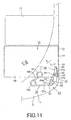
- the torsion coil spring 39 biases the shutter unit 15 into movement along the arrow A in Fig. 10.
- the shutter unit 15 is moved in a direction of opening the aperture for the head part 13, to retain the aperture for the head part 13 in the opened position, as shown in Figs. 11 and 12
- the shutter unit 15 When the disc cartridge 1, in a state in which the shutter unit 15 retains the aperture for the head part 13 in the opened position, is taken out from the disc recording and/or reproducing apparatus, by way of performing the operation for ejection, the shutter unit 15 is moved along the direction of arrow B in Fig. 10, relative to the main cartridge body unit 5, with the center coil part 39c being similarly moved along the direction of arrow B. When the shutter unit 15 is further moved along the direction of arrow B, such that it surpasses the location of the support pin 42 along the direction of movement of the shutter unit 15, the biasing direction is reversed.
- the torsion coil spring 39 biases the shutter unit 15 into movement along the arrow B in Fig.9, such that the shutter unit 15 is moved in the direction of closing the aperture for the head part 13, thereby retaining the aperture for the head part in the closed state.
- the shutter unit 15, biased by the torsion coil spring 39, forming the bi-directional energizing unit, is carried in the position of closing the aperture for the head part 13 and in the position of opening the aperture for the head part 13, under the biasing force of the torsion coil spring 39, and hence may be maintained reliably in the position of closing or opening the aperture for the head part 13.
- the shutter unit 15 may be reliably retained in the position of closing the aperture for the head part 13, while the reliable opening/ closure operation for the aperture for the head part 13 may be achieved.
- the lateral surface 8 of the main cartridge body unit 5, carrying the shutter unit 15, is formed with a guide groove 49, into which is intruded a shutter unit releasing piece, provided to the disc recording and/or reproducing apparatus, as shown in Figs.1, 6 and 12.
- first and second positioning holes 43, 44 engaged by positioning pins, provided to the disc recording and/or reproducing apparatus, as shown in Figs.2 and 3.
- the second positioning hole 44 is formed as an elongated hole, having the width-wise direction, lying at right angles to the direction of movement of the shutter unit 15, as a long radius.
- first and second engagement recesses 45, 46 engaged by a portion of a cartridge loading unit provided to the recording and/or reproducing apparatus or a portion of a loading controlling member provided to the recording and/or reproducing apparatus, as shown in Figs.1 and 2.
- a third engagement recess 47 engaged by a portion of an ejection unit provided to the recording and/or reproducing apparatus, as shown in Fig.3.
- a fourth engagement recess 48 is formed in a flat lateral side 9 of the main cartridge body unit 5, formed with the engagement recess 47 for ejection of the main cartridge body unit 5, there is formed a fourth engagement recess 48.
- the third engagement recess 47 is formed so that one lateral side thereof is proximate to a center P3 along the longitudinal direction of an area of the lateral side of the arcuate section 7 of the main cartridge body unit 5, as shown in Fig.4.
- the longitudinal direction is coincident with the inserting direction of the main cartridge body unit 5 into the recording and/or reproducing apparatus. That is, the third engagement recess 47 is formed towards the inserting direction from a center P3 into the recording and/or reproducing apparatus.
- a cut-out 49 formed in a direction opposite to the inserting direction, as shown in Fig. 13. This cut-out is formed to delimit a lug 49a at a location of the third engagement recess 47 opposite to the direction of insertion E into the recording and/or reproducing apparatus for protruding in the inserting direction.
- the fourth engagement recess 48 is formed as a rectangular-shaped recess opened in the lateral surface 9 of the main cartridge body unit 5.
- the ejection lever may reliably be engaged with the disc cartridge 1 by having the distal end of the ejection lever, as a part of the ejection unit provided to the recording and/or reproducing apparatus, engaged with the surface formed with the cut-out 49.
- the inclined cut-out 49a is able to take up the tilt to achieve reliable engagement.
- the present disc cartridge 1 may reliably be engaged with the ejection unit, the bias force for ejecting the disc cartridge 1 may be stored in the ejection unit as a result of the insertion into the recording and/or reproducing apparatus.
- the result is that, by employing the disc cartridge 1 according to the present invention, a recording and/or reproducing apparatus, enabling reliable ejection, may be achieved.
- the recording and/or reproducing apparatus may be reduced in size without constraint as to the mounting position of the ejection unit.
- the loading operation to the recording and/or reproducing apparatus may be achieved by exploiting only the lateral surface 9, by engaging the loading unit with the fourth engagement recess 48, as a part of the orientation control unit for controlling the inserting direction of the disc cartridge 1 is engaged e.g. with the third engagement recess 47 to control the orientation of insertion into the recording and/or reproducing apparatus. Since the lateral side 8 of the disc cartridge 1, carrying the shutter unit 15, is carried by a shutter releasing means, adapted for releasing the shutter unit 15, the loading operation becomes possible by exploiting only one lateral side 9 of the disc cartridge 1.
- the loading unit may be provided only on one side of the disc cartridge 1, according to the present invention, the recording and/or reproducing apparatus provided with the loading unit may readily be reduced in size.
- a discriminating opening or a discriminating recess for identifying the sort of the optical disc 2 is provided as necessary.
- the disc cartridge 1, according to the present invention is inserted into the recording and/or reproducing apparatus, with the semi-circular arcuate section 7 as an inserting end, so that it is loaded on or unloaded from the apparatus as the user grips the back side curved section 10, opposite to the arcuate section 7.
- the disc cartridge 1 is formed to an extremely small size.
- a roughed surface for anti-slip 48 may be provided on the back surface of the lower cartridge half 4, for assuring reliable gripping by hand or finger during loading/unloading on or from the recording and/or reproducing apparatus, as shown in Fig.14.
- This roughed surface 48 is provided on the back surface formed as the curved section 10 of the lower cartridge half 4.
- the roughed surface 48 may also be provided to the upper cartridge half 3. In this case, the roughed surface 48 is provided facing the roughed surface 48 of the lower cartridge half 4.
- the disc cartridge 1 there is housed the optical disc 2, having recorded thereon the program data or video data needed for executing e.g. a TV game.
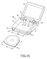
- the disc recording and/or reproducing apparatus employing the disc cartridge 1 of the present invention, housing this sort of the optical disc 2, is made up by a main body unit of the apparatus 51, carrying the disc cartridge 1, and having enclosed therein a disc driving unit for reproducing at least data recorded on the optical disc, and by a display 52 for demonstrating image data or text data reproduced from the optical disc 2, as shown in Fig. 15.
- a cartridge loading unit including a cartridge holder for loading the disc cartridge 1 thereon.
- a cartridge inserting/ejecting opening 53 for inserting the disc cartridge 1 into a cartridge holder and for ejecting the disc cartridge 1 loaded in the cartridge holder.
- the cartridge inserting/ejecting opening 53 is formed as an opening just large enough to permit insertion/ removal of the disc cartridge 1, and has a width W2 and a height H2 slightly larger than the width W 1 and a thickness D1, respectively, of the disc cartridge 1 inserted therein.
- a cartridge holder 54 facing the cartridge inserting/ejecting opening 53.
- an ejection button 55 for ejecting the disc cartridge 1 held by the cartridge holder 54.
- buttons 56, 57 of a control switch used for carrying out e.g. a TV game.
- a control key 58 for scrolling the image demonstrated on the display 52.
- a loudspeaker 59 for radiating audio signals reproduced from the optical disc 2.
- a control bobbin for e.g. a reproducing button, for controlling the disc driving unit, and an actuating button for a power supply switch, are provided to the main body unit of the apparatus 51.
- the display 52 is provided on the back side, opposite to the front side, carrying the cartridge inserting/ejecting opening 53 of the main body unit of the apparatus 51, for swinging relative to the main body unit of the apparatus 51 via a hinge unit 60.
- the display 52 may be swung towards the main body unit of the apparatus 51 so as to be superposed on the upper surface thereof.
- the display 52 is formed by a liquid crystal display panel.
- the disc cartridge 1 For loading the disc cartridge 1 on the disc driving device 50, the disc cartridge 1 is inserted via the cartridge inserting/ejecting opening 53 into the main body unit of the apparatus 51, with the arcuate section 7 as the inserting side, so as to be held on the cartridge holder 54, as shown in Fig. 15.
- the inserting end thereof via the cartridge inserting/ejecting opening 53 is formed as the approximately semicircular arcuate section 7, so that, even when the disc cartridge 1 is inserted with a centerline P2 along the widthwise direction of the disc cartridge significantly inclined with respect to the centerline P1 along the width-wise direction of the cartridge inserting/ejecting opening 53, the disc cartridge can be smoothly inserted into the cartridge inserting/ejecting opening 53 and reliably held by the cartridge holder 54.
- the disc cartridge 1, having the inserting end formed as the approximately semicircular arcuate section 7, may be inserted into the main body unit of the apparatus 51 at the approximately semicircular arcuate section 7, even in case the disc cartridge 1 is inserted via the cartridge inserting/ejecting opening 53 with the width-wise centerline P2 inclined by an angle up to approximately 45° towards left or right of the width-wise centerline P1 of the cartridge inserting/ejecting opening 53, as shown in Figs. 16 or 17.
- the disc cartridge 1 may be corrected in its orientation by rotating it in a direction causing the coincidence of the centerlines P1 and P2, in the course of the insertion thereof through the cartridge inserting/ejecting opening 53, with the portion of the arcuate section 7, abutting against one of the lateral sides of the cartridge inserting/ejecting opening 53, as the center of rotation, as shown in Fig. 18.
- the disc cartridge 1, according to the present invention may reliably be inserted into the cartridge holder 54, even in case the inserting direction thereof through the cartridge inserting/ejecting opening 53 is inclined significantly.
- the disc cartridge 1, inserted into the cartridge holder 54, is further introduced into the cartridge holder 54, whereby the shutter unit 15 is moved relative to the main body unit of the apparatus 51 to open the aperture for the head part 13. That is, when the disc cartridge 1 has been introduced halfway in the cartridge holder 54, as shown in Fig.19, a portion of a shutter unit movement inhibit spring 62, formed by segmenting a part of the sidewall section of an L-shaped cartridge retention part 61 in one lateral side of the cartridge holder 54, is intruded into the window 33 formed in the connecting piece 21 of the shutter unit 15, thereby thrusting the thrust part 30 to cause rotation of the lock lever 28 in the direction indicated by arrow D in Fig.9, as described previously.
- the lock lever 28 When rotated in the direction indicated by arrow D in Fig.9, the lock lever 28 is disengaged from the mating engaging part 29 of the engagement piece 31 to release the lock of the shutter unit 15 with respect to the main cartridge body unit 5.
- the shutter unit 15 When unlocked from the main cartridge body unit 5, the shutter unit 15 is movable relative to the main cartridge body unit 5.
- the cartridge holder 54 on which is loaded the disc cartridge 1 according to the present invention, is further provided with a shutter releasing piece 63.
- This shutter releasing piece 63 is intruded into a guide groove 49, formed in the lateral surface 8 of the main cartridge body unit 5, until it abuts against the lateral side of the shutter unit 15.
- the shutter releasing piece 63 When inserted into the inside of the cartridge holder 54, until unlocking of the shutter unit 15, the shutter releasing piece 63 abuts against the lateral side of the shutter unit 15, to inhibit the movement of the shutter unit 15 relative to the main cartridge body unit 5, as shown in Fig.19.
- the disc cartridge 1 When the disc cartridge 1 is further intruded from the position shown in Fig.19 towards the inner part of the cartridge holder 54, in the direction indicated by arrow E, the main cartridge body unit 5 is moved along the direction as indicated by arrow E, thereby opening the aperture for the head part 13, as shown in Fig.20.
- the disc cartridge 1 is moved in the direction indicated by arrow E in Fig.19, with the main cartridge body unit 5 then opening the aperture for the head part 13, the torsion coil spring 39, forming the shutter opening/ closure unit 38, is biased, as described above with reference to Figs.9 and 10.
- the main cartridge body unit 5 is moved in the direction indicated by arrow E in Fig. 19, such that the coil part 39c surpasses the location of the support pin 42, lying along the direction of movement of the shutter unit 15, thus biasing the torsion coil spring 39, the biasing direction of the torsion coil spring 39 is reversed.
- the shutter unit 15 is then moved in the direction of arrow F in Fig.18, opposite to the direction of movement of the main cartridge body unit 5, thus opening the aperture for the head part 13, as shown in Figs.11, 12 and 18. At this time, the shutter unit 15 is biased by the torsion coil spring 39 for opening the aperture for the head part 13, thus reliably retaining the aperture for the head part 13 in the opened state.
- an ejection button 55 is pressed for ejecting the disc cartridge 1, loaded on the disc driving device 50, after reproducing the optical disc 2, an ejection button 55 is pressed. On pressing the ejection button 55, the disc cartridge 1, loaded on the cartridge loading section, is ejected. After the ejection operation is carried out, the shutter unit 15 is moved relative to the main cartridge body unit 5 to revert to the initial position of closing the aperture for the head part 13 to lock the shutter unit 15 in this position of closing the aperture for the head part 13, by the reverse of the operation, described above. By this operation of restoring the shutter unit 15 to the closure position, the disc cartridge is ejected via the cartridge loading/unloading opening 53, so that the ejection of the disc cartridge 1, loaded on the disc driving device 50, comes to a close.
- the cartridge loading section 67 is mounted on a base 69 carrying a disc rotating driving unit 65 and an optical pickup 68 for reproducing the data recorded on the optical disc 2.
- the cartridge loading section 67 is provided with a positioning pin 70 for positioning the disc cartridge 1 in the planar direction and a positioning lug, not shown, for positioning the disc cartridge 1 in the height-wise direction.
- the disc cartridge 1 is loaded on the cartridge loading section 67, as it is positioned in the planar and height-wise directions, by the positioning pin 70 engaging in each of the first and second positioning holes 43, 44 and by the lower surface being supported by the height positioning lug.
- the portion facing the aperture for the head part 13 of the upstanding peripheral wall section 4a of the lower cartridge half 4 is formed with the cut-out 25 and thereby opened.
- At least the portion facing the aperture for the head part 13 of the slide guide 18 carrying the shutter unit 15 provided to the upper cartridge half 3 is of a height H1 not protruding from the lower surface 2a of the optical disc 2 facing the lower cartridge half 4, as shown in Fig.7, when the optical disc 2 in the disc cartridge 1, loaded in position in the height-wise direction on the cartridge loading section 67has been loaded in position on the turntable 6.
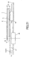
- the disc cartridge 1, constructed as described above, is able not only to locate an entire optical pickup 68, as a head part for reading out information signals, recorded on the optical disc, within the main cartridge body unit 5, as shown in Fig.21, when the shutter unit 15 has been moved to open the aperture for the head part 13, but also to locate the components of the optical block 72, other than an objective lens 71, condensing the light beam, scanning the signal recording area of the optical disc 2, outwardly of the main cartridge body unit 5, as the objective lens 71 is located within the main cartridge body unit 5, as shown in Fig.22, when the optical pickup 68 has been moved to a position scanning the outer rim of the optical disc 2.
- the optical pickup 68 may be located at an optional position across the inner and outer rims of the main cartridge body unit 5, as the optical pickup is kept in proximity to the optical disc 2, and hence the signal recording area may be provided up to the outer rim of the optical disc 2, thus increasing the recording capacity of the optical disc 2.
- the optical pickup 68 since the optical pickup 68 may be located in proximity to the optical disc 2, the numerical aperture NA of the objective lens 71 may be increased, and hence the beam spot of the light beam condensed on the signal recording area of the optical disc 2 may be reduced, thereby improving the recording density of the information signals recorded on the optical disc 2.
- the optical disc 2 of a preset recording capacity may be reduced in size.
- the optical disc 2 may be scanned as the optical pickup 68 is located at an optional position across the inner and outer rims of the main cartridge body unit 5, the main cartridge body unit 5 and hence the recording and/or reproducing apparatus employing it may be reduced in size.
- the present invention may similarly be applied to a recording and/or reproducing optical disc adapted for re-recording the information signals or other types of the recording mediums with comparable merits.
Landscapes
- Feeding And Guiding Record Carriers (AREA)
- Holding Or Fastening Of Disk On Rotational Shaft (AREA)
- Packaging For Recording Disks (AREA)
Applications Claiming Priority (4)
| Application Number | Priority Date | Filing Date | Title |
|---|---|---|---|
| JP2003281391A JP2005050426A (ja) | 2003-07-28 | 2003-07-28 | ディスクカートリッジ |
| JP2003281395 | 2003-07-28 | ||
| JP2004140491A JP4547982B2 (ja) | 2003-07-28 | 2004-05-10 | ディスクカートリッジ |
| PCT/JP2004/010515 WO2005010885A1 (fr) | 2003-07-28 | 2004-07-23 | Cartouche de disque |
Publications (3)
| Publication Number | Publication Date |
|---|---|
| EP1650764A1 true EP1650764A1 (fr) | 2006-04-26 |
| EP1650764A4 EP1650764A4 (fr) | 2009-02-25 |
| EP1650764B1 EP1650764B1 (fr) | 2011-02-23 |
Family
ID=34108581
Family Applications (1)
| Application Number | Title | Priority Date | Filing Date |
|---|---|---|---|
| EP04770908A Expired - Fee Related EP1650764B1 (fr) | 2003-07-28 | 2004-07-23 | Cartouche de disque |
Country Status (7)
| Country | Link |
|---|---|
| US (1) | US7356827B2 (fr) |
| EP (1) | EP1650764B1 (fr) |
| KR (1) | KR101059093B1 (fr) |
| DE (1) | DE602004031531D1 (fr) |
| MY (1) | MY137809A (fr) |
| TW (1) | TW200519859A (fr) |
| WO (1) | WO2005010885A1 (fr) |
Families Citing this family (1)
| Publication number | Priority date | Publication date | Assignee | Title |
|---|---|---|---|---|
| US20100310076A1 (en) * | 2009-06-04 | 2010-12-09 | Ron Barzilai | Method for Performing Double Domain Encryption in a Memory Device |
Citations (3)
| Publication number | Priority date | Publication date | Assignee | Title |
|---|---|---|---|---|
| EP0936608A2 (fr) * | 1998-02-11 | 1999-08-18 | Iomega Corporation | Appareil pour déverrouiller une cassette à verrouillage de volet |
| EP1122727A2 (fr) * | 2000-02-04 | 2001-08-08 | Sony Corporation | Cassette à disque et méthode de chargement de cassette à disque |
| JP2002056601A (ja) * | 1999-11-12 | 2002-02-22 | Sony Corp | ディスクカートリッジ装置及びディスクカートリッジ |
Family Cites Families (26)
| Publication number | Priority date | Publication date | Assignee | Title |
|---|---|---|---|---|
| JPH076493A (ja) | 1993-06-21 | 1995-01-10 | Matsushita Electric Ind Co Ltd | 光ディスク装置およびディスクカートリッジ |
| JPH10334630A (ja) * | 1997-06-04 | 1998-12-18 | Sony Corp | ディスクカートリッジ |
| US6122141A (en) * | 1997-08-29 | 2000-09-19 | Iomega Corporation | Cartridge retention mechanism for a removable cartridge drive |
| US6256168B1 (en) * | 1997-11-12 | 2001-07-03 | Iomega Corporation | Shutter liner for a disk cartridge |
| US5930090A (en) * | 1997-11-12 | 1999-07-27 | Iomega Corporation | Data cartridge with compression return spring following arcuate guide |
| JP4006809B2 (ja) * | 1998-02-02 | 2007-11-14 | ソニー株式会社 | 情報記憶媒体カートリッジ |
| JP3900685B2 (ja) | 1998-06-10 | 2007-04-04 | ソニー株式会社 | ディスクカートリッジ及びディスクドライブ装置 |
| JP2000153891A (ja) * | 1998-09-17 | 2000-06-06 | Sony Corp | ディスク状記録媒体用のパッケ―ジ及びパッケ―ジシステム |
| JP2000156061A (ja) * | 1998-11-16 | 2000-06-06 | Sanyo Electric Co Ltd | ディスクカートリッジ |
| BE1012279A3 (fr) * | 1998-11-18 | 2000-08-01 | Staar Sa | Boitiers pour support de donnees. |
| JP3469823B2 (ja) * | 1999-07-08 | 2003-11-25 | 三洋電機株式会社 | ディスクを収納したカートリッジ及び該ディスクへの信号記録又は再生装置 |
| JP2001035118A (ja) * | 1999-07-22 | 2001-02-09 | Canon Inc | 光磁気ディスクカートリッジおよび光磁気ディスク装置 |
| JP2001229638A (ja) | 1999-12-08 | 2001-08-24 | Matsushita Electric Ind Co Ltd | ディスクカートリッジ及びディスク駆動装置 |
| US6526018B1 (en) * | 1999-12-08 | 2003-02-25 | Matsushita Electric Industrial Co., Ltd. | Disk cartridge |
| JP4457287B2 (ja) | 2000-05-11 | 2010-04-28 | ソニー株式会社 | 記録媒体カートリッジホルダ及び記録及び/又は再生装置 |
| JP2001357650A (ja) * | 2000-06-13 | 2001-12-26 | Hitachi Maxell Ltd | ディスク駆動装置 |
| JP2002175678A (ja) * | 2000-09-26 | 2002-06-21 | Hitachi Maxell Ltd | 誤挿入防止機能を有するカートリッジと駆動装置 |
| US20020126614A1 (en) * | 2001-01-31 | 2002-09-12 | Dataplay, Inc. | Mechanism and method for opening shutter of data cartridge in disk drive |
| US6865060B2 (en) * | 2001-04-26 | 2005-03-08 | Matsushita Electric Industrial Co., Ltd. | Disk drive device having a lifting plate configured to lift a magnetic head supporting member |
| JP2002367268A (ja) | 2001-06-04 | 2002-12-20 | Matsushita Electric Ind Co Ltd | ディスク装置 |
| JP2003030949A (ja) * | 2001-07-12 | 2003-01-31 | Sony Corp | ディスクカートリッジ |
| JP3919084B2 (ja) * | 2001-11-21 | 2007-05-23 | 富士フイルム株式会社 | 磁気ディスクカートリッジ |
| TWI254923B (en) * | 2002-07-15 | 2006-05-11 | Hitachi Maxell | CD storage cassette |
| JP2004362731A (ja) * | 2003-05-12 | 2004-12-24 | Sony Computer Entertainment Inc | ディスクカートリッジおよびディスクカートリッジを装着する装置 |
| KR101059493B1 (ko) * | 2003-07-28 | 2011-08-25 | 소니 가부시키가이샤 | 디스크 카트리지용 셔터 부재, 디스크 카트리지 및 디스크 기록 또는 재생 장치 |
| JP2005267826A (ja) * | 2004-02-18 | 2005-09-29 | Sony Corp | 記録媒体ドライブ装置、これを備えた電子機器及び記録媒体カートリッジ |
-
2004
- 2004-07-23 DE DE602004031531T patent/DE602004031531D1/de active Active
- 2004-07-23 EP EP04770908A patent/EP1650764B1/fr not_active Expired - Fee Related
- 2004-07-23 WO PCT/JP2004/010515 patent/WO2005010885A1/fr active Application Filing
- 2004-07-23 US US10/528,669 patent/US7356827B2/en not_active Expired - Fee Related
- 2004-07-23 KR KR1020057004740A patent/KR101059093B1/ko not_active IP Right Cessation
- 2004-07-27 TW TW093122414A patent/TW200519859A/zh not_active IP Right Cessation
- 2004-07-27 MY MYPI20043003A patent/MY137809A/en unknown
Patent Citations (3)
| Publication number | Priority date | Publication date | Assignee | Title |
|---|---|---|---|---|
| EP0936608A2 (fr) * | 1998-02-11 | 1999-08-18 | Iomega Corporation | Appareil pour déverrouiller une cassette à verrouillage de volet |
| JP2002056601A (ja) * | 1999-11-12 | 2002-02-22 | Sony Corp | ディスクカートリッジ装置及びディスクカートリッジ |
| EP1122727A2 (fr) * | 2000-02-04 | 2001-08-08 | Sony Corporation | Cassette à disque et méthode de chargement de cassette à disque |
Non-Patent Citations (1)
| Title |
|---|
| See also references of WO2005010885A1 * |
Also Published As
| Publication number | Publication date |
|---|---|
| EP1650764B1 (fr) | 2011-02-23 |
| KR20060039388A (ko) | 2006-05-08 |
| KR101059093B1 (ko) | 2011-08-25 |
| TW200519859A (en) | 2005-06-16 |
| WO2005010885A1 (fr) | 2005-02-03 |
| US7356827B2 (en) | 2008-04-08 |
| MY137809A (en) | 2009-03-31 |
| DE602004031531D1 (de) | 2011-04-07 |
| US20060010455A1 (en) | 2006-01-12 |
| EP1650764A4 (fr) | 2009-02-25 |
| TWI304571B (fr) | 2008-12-21 |
Similar Documents
| Publication | Publication Date | Title |
|---|---|---|
| US6473392B2 (en) | Disc cartridge | |
| US6717907B2 (en) | Disc cartridge | |
| US6356527B1 (en) | Shutter assembly for a disc cartridge | |
| US7730504B2 (en) | Disc cartridge | |
| US7475410B2 (en) | Disc recording and/or playback apparatus | |
| US7526782B2 (en) | Shutter member for disc cartridge, disc cartridge and disc recording/reproducing apparatus | |
| US7356827B2 (en) | Disk cartridge | |
| EP1650762B1 (fr) | Cartouche de disque, et dispositif d'enregistrement et/ou de reproduction de disque | |
| JP4706169B2 (ja) | ディスクカートリッジ | |
| JP4547982B2 (ja) | ディスクカートリッジ | |
| JP4706185B2 (ja) | ディスクカートリッジ | |
| JP2005050426A (ja) | ディスクカートリッジ | |
| RU2429551C2 (ru) | Картридж для диска | |
| JP2005063638A (ja) | ディスクカートリッジ及びディスク記録及び/又は再生装置 | |
| JP2005063636A (ja) | ディスクカートリッジ及びディスク記録及び/又は再生装置 |
Legal Events
| Date | Code | Title | Description |
|---|---|---|---|
| PUAI | Public reference made under article 153(3) epc to a published international application that has entered the european phase |
Free format text: ORIGINAL CODE: 0009012 |
|
| 17P | Request for examination filed |
Effective date: 20050318 |
|
| AK | Designated contracting states |
Kind code of ref document: A1 Designated state(s): DE FR GB |
|
| DAX | Request for extension of the european patent (deleted) | ||
| RBV | Designated contracting states (corrected) |
Designated state(s): DE FR GB |
|
| A4 | Supplementary search report drawn up and despatched |
Effective date: 20090122 |
|
| RIC1 | Information provided on ipc code assigned before grant |
Ipc: G11B 17/04 20060101ALI20090116BHEP Ipc: G11B 23/03 20060101AFI20050209BHEP |
|
| 17Q | First examination report despatched |
Effective date: 20090427 |
|
| GRAP | Despatch of communication of intention to grant a patent |
Free format text: ORIGINAL CODE: EPIDOSNIGR1 |
|
| GRAS | Grant fee paid |
Free format text: ORIGINAL CODE: EPIDOSNIGR3 |
|
| GRAA | (expected) grant |
Free format text: ORIGINAL CODE: 0009210 |
|
| AK | Designated contracting states |
Kind code of ref document: B1 Designated state(s): DE FR GB |
|
| REG | Reference to a national code |
Ref country code: GB Ref legal event code: FG4D |
|
| REF | Corresponds to: |
Ref document number: 602004031531 Country of ref document: DE Date of ref document: 20110407 Kind code of ref document: P |
|
| REG | Reference to a national code |
Ref country code: DE Ref legal event code: R096 Ref document number: 602004031531 Country of ref document: DE Effective date: 20110407 |
|
| PGFP | Annual fee paid to national office [announced via postgrant information from national office to epo] |
Ref country code: FR Payment date: 20110729 Year of fee payment: 8 |
|
| PGFP | Annual fee paid to national office [announced via postgrant information from national office to epo] |
Ref country code: GB Payment date: 20110721 Year of fee payment: 8 Ref country code: DE Payment date: 20110722 Year of fee payment: 8 |
|
| PLBE | No opposition filed within time limit |
Free format text: ORIGINAL CODE: 0009261 |
|
| STAA | Information on the status of an ep patent application or granted ep patent |
Free format text: STATUS: NO OPPOSITION FILED WITHIN TIME LIMIT |
|
| 26N | No opposition filed |
Effective date: 20111124 |
|
| REG | Reference to a national code |
Ref country code: DE Ref legal event code: R097 Ref document number: 602004031531 Country of ref document: DE Effective date: 20111124 |
|
| GBPC | Gb: european patent ceased through non-payment of renewal fee |
Effective date: 20120723 |
|
| REG | Reference to a national code |
Ref country code: FR Ref legal event code: ST Effective date: 20130329 |
|
| PG25 | Lapsed in a contracting state [announced via postgrant information from national office to epo] |
Ref country code: GB Free format text: LAPSE BECAUSE OF NON-PAYMENT OF DUE FEES Effective date: 20120723 Ref country code: FR Free format text: LAPSE BECAUSE OF NON-PAYMENT OF DUE FEES Effective date: 20120731 Ref country code: DE Free format text: LAPSE BECAUSE OF NON-PAYMENT OF DUE FEES Effective date: 20130201 |
|
| REG | Reference to a national code |
Ref country code: DE Ref legal event code: R119 Ref document number: 602004031531 Country of ref document: DE Effective date: 20130201 |