EP1650480A1 - Dichtungsanordnung für Lager - Google Patents
Dichtungsanordnung für Lager Download PDFInfo
- Publication number
- EP1650480A1 EP1650480A1 EP05109678A EP05109678A EP1650480A1 EP 1650480 A1 EP1650480 A1 EP 1650480A1 EP 05109678 A EP05109678 A EP 05109678A EP 05109678 A EP05109678 A EP 05109678A EP 1650480 A1 EP1650480 A1 EP 1650480A1
- Authority
- EP
- European Patent Office
- Prior art keywords
- sealing
- shield
- bearing
- sealing device
- annular shield
- Prior art date
- Legal status (The legal status is an assumption and is not a legal conclusion. Google has not performed a legal analysis and makes no representation as to the accuracy of the status listed.)
- Withdrawn
Links
- 238000007789 sealing Methods 0.000 title claims abstract description 48
- 239000013013 elastic material Substances 0.000 claims abstract 3
- 229910001220 stainless steel Inorganic materials 0.000 claims description 6
- 239000010935 stainless steel Substances 0.000 claims description 6
- 239000000463 material Substances 0.000 claims description 5
- 230000003068 static effect Effects 0.000 claims description 4
- 239000002184 metal Substances 0.000 claims description 2
- 229910000831 Steel Inorganic materials 0.000 claims 1
- 239000010959 steel Substances 0.000 claims 1
- 238000005096 rolling process Methods 0.000 abstract description 3
- 239000003795 chemical substances by application Substances 0.000 description 4
- 239000013536 elastomeric material Substances 0.000 description 3
- 238000004519 manufacturing process Methods 0.000 description 3
- 239000000314 lubricant Substances 0.000 description 2
- 230000002411 adverse Effects 0.000 description 1
- 230000004888 barrier function Effects 0.000 description 1
- 230000007547 defect Effects 0.000 description 1
- 230000002950 deficient Effects 0.000 description 1
- 230000009977 dual effect Effects 0.000 description 1
- 239000000428 dust Substances 0.000 description 1
- 239000012530 fluid Substances 0.000 description 1
- 239000004519 grease Substances 0.000 description 1
- 239000011499 joint compound Substances 0.000 description 1
- 238000004073 vulcanization Methods 0.000 description 1
- 239000002699 waste material Substances 0.000 description 1
- XLYOFNOQVPJJNP-UHFFFAOYSA-N water Substances O XLYOFNOQVPJJNP-UHFFFAOYSA-N 0.000 description 1
Images
Classifications
-
- F—MECHANICAL ENGINEERING; LIGHTING; HEATING; WEAPONS; BLASTING
- F16—ENGINEERING ELEMENTS AND UNITS; GENERAL MEASURES FOR PRODUCING AND MAINTAINING EFFECTIVE FUNCTIONING OF MACHINES OR INSTALLATIONS; THERMAL INSULATION IN GENERAL
- F16C—SHAFTS; FLEXIBLE SHAFTS; ELEMENTS OR CRANKSHAFT MECHANISMS; ROTARY BODIES OTHER THAN GEARING ELEMENTS; BEARINGS
- F16C33/00—Parts of bearings; Special methods for making bearings or parts thereof
- F16C33/72—Sealings
- F16C33/76—Sealings of ball or roller bearings
- F16C33/78—Sealings of ball or roller bearings with a diaphragm, disc, or ring, with or without resilient members
- F16C33/7869—Sealings of ball or roller bearings with a diaphragm, disc, or ring, with or without resilient members mounted with a cylindrical portion to the inner surface of the outer race and having a radial portion extending inward
- F16C33/7879—Sealings of ball or roller bearings with a diaphragm, disc, or ring, with or without resilient members mounted with a cylindrical portion to the inner surface of the outer race and having a radial portion extending inward with a further sealing ring
- F16C33/7883—Sealings of ball or roller bearings with a diaphragm, disc, or ring, with or without resilient members mounted with a cylindrical portion to the inner surface of the outer race and having a radial portion extending inward with a further sealing ring mounted to the inner race and of generally L-shape, the two sealing rings defining a sealing with box-shaped cross-section
-
- F—MECHANICAL ENGINEERING; LIGHTING; HEATING; WEAPONS; BLASTING
- F16—ENGINEERING ELEMENTS AND UNITS; GENERAL MEASURES FOR PRODUCING AND MAINTAINING EFFECTIVE FUNCTIONING OF MACHINES OR INSTALLATIONS; THERMAL INSULATION IN GENERAL
- F16J—PISTONS; CYLINDERS; SEALINGS
- F16J15/00—Sealings
- F16J15/16—Sealings between relatively-moving surfaces
- F16J15/32—Sealings between relatively-moving surfaces with elastic sealings, e.g. O-rings
- F16J15/3248—Sealings between relatively-moving surfaces with elastic sealings, e.g. O-rings provided with casings or supports
- F16J15/3252—Sealings between relatively-moving surfaces with elastic sealings, e.g. O-rings provided with casings or supports with rigid casings or supports
- F16J15/3256—Sealings between relatively-moving surfaces with elastic sealings, e.g. O-rings provided with casings or supports with rigid casings or supports comprising two casing or support elements, one attached to each surface, e.g. cartridge or cassette seals
- F16J15/3264—Sealings between relatively-moving surfaces with elastic sealings, e.g. O-rings provided with casings or supports with rigid casings or supports comprising two casing or support elements, one attached to each surface, e.g. cartridge or cassette seals the elements being separable from each other
Definitions
- the present invention refers a sealing device for bearings of motor vehicle wheel hubs.
- the invention is intended for use, particularly but not exclusively, with heavy motor vehicles.
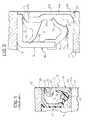
- FIG. 1 shows a cross sectional view of a conventional sealing device 10 which serves to seal an annular gap 11 between the races 12 and 13 of a bearing.
- the sealing device 10 comprises a first metallic annular shield 14 (called “ flinger ”) secured to the radially inner, stationary race 13 of the bearing and a second metallic annular shield 15 secured to the radially outer, rotating race 12 of the bearing.
- Fixed to the stationary shield 15 is a sealing gasket 16 of elastomeric material with a V shape having two sealing lips 17, 18 slidingly engaging the opposite shield 14.
- the radial sealing lip 17 is engaged against a cylindrical axial portion 19 of the shield 14.
- the axial sealing lip 18 is elongated and flexible and slidingly engages a radial wall portion 20 of the shield 14. Contact of the radial lip 17 is usually ensured by a circumferential spring 21.
- sealing devices of the above-mentioned type are disclosed in EP-A-0 937 984 and EP-A-1 008 775. Sealing devices of this type carry out the dual task of:
- the shield 14 Fixed by vulcanization to the end portion of the shield 14 facing the outer race 12 is a gasket 22 having a radial sealing lip 23 which slides against an axial cylindrical portion 25 of the shield 15.
- the shield 14 is made of stainless steel so as not to be attacked by contaminating agents to which it is exposed on the axially outer side of the bearing (to the right in Figure 1).
- a rubber film 29 (about 5 microns thick) is interposed between these two elements.
- This film commonly known as "Bore-tite” in the field, covers possible scratches on the outer race which may constitute passages for external fluids or the lubricant contained within the bearing.
- a gasket 16 of elastomeric material having a substantially V-shaped cross-section is fixed to a metallic annular shield 15 secured to an outer, rotatable race 12 of a bearing.
- An annular metallic shield (or flinger) 14 is fixed to the inner stationary race 13 of the bearing.
- Shield 14 has a substantially L-shaped cross section with a cylindrical axial portion 19 fixed to a coaxial, cylindrical surface 13a of inner race 13, and a radial wall portion 20 extending towards the outer race 12 of the bearing.
- the gasket 16 forms a radial sealing lip 17 intended to radially contact the cylindrical portion 19 of shield 14. Further, the gasket 16 forms an elongated axial sealing lip 18 for elastically contacting the radial wall 20 of shield 14.
- annular gasket 22 forming, as a single piece:
- the gasket 22 achieves the following advantages.
- the static sealing lip 28, formed as a single piece with the gasket 22, allows to eliminate the conventional rubber film indicated 29 in Figure 1. This simplifies and accelerates the step of assembling the sealing device in the bearing and eliminates costs related to the manufacturing of the said film.
- the covering layer 22c allows to use a flinger 14 made of a material different from stainless steel, conventionally used. For example, a cheaper and non-inoxidable metal may be used, which will be protected by the layer 22c anyway.
- a non-inoxidable material for the flinger 14 for example a non-stainless steel, adhesion of the rubber of gasket 22 to the flinger is improved. This increases the useful life, the efficiency and reliability of the sealing device.
- the axial sealing lip 24 is optional. However, this lip forms an additional barrier that hinders considerably the access of external contaminating agents to the inner parts of the bearing.
- the thickness of the covering layer 22c may vary locally, for instance forming a number of small seats or notches (not shown) on the outer surface in order to facilitate gripping the gasket by means of mechanical tool used for fitting the sealing device between the races of the bearing.
Landscapes
- Engineering & Computer Science (AREA)
- General Engineering & Computer Science (AREA)
- Mechanical Engineering (AREA)
- Sealing Of Bearings (AREA)
- Gripping On Spindles (AREA)
- Wire Bonding (AREA)
Applications Claiming Priority (1)
| Application Number | Priority Date | Filing Date | Title |
|---|---|---|---|
| ITTO20040133 ITTO20040133U1 (it) | 2004-10-20 | 2004-10-20 | Dispositivo di tenuta per cuscinetti |
Publications (1)
| Publication Number | Publication Date |
|---|---|
| EP1650480A1 true EP1650480A1 (de) | 2006-04-26 |
Family
ID=35429374
Family Applications (1)
| Application Number | Title | Priority Date | Filing Date |
|---|---|---|---|
| EP05109678A Withdrawn EP1650480A1 (de) | 2004-10-20 | 2005-10-18 | Dichtungsanordnung für Lager |
Country Status (2)
| Country | Link |
|---|---|
| EP (1) | EP1650480A1 (de) |
| IT (1) | ITTO20040133U1 (de) |
Cited By (4)
| Publication number | Priority date | Publication date | Assignee | Title |
|---|---|---|---|---|
| EP2093574A1 (de) | 2008-02-19 | 2009-08-26 | Aktiebolaget SKF | Kombinierte Vorrichtung zur Dreherfassung und Abdichtung von Lagern |
| GB2459503A (en) * | 2008-04-25 | 2009-10-28 | Pioneer Weston Internat Ltd | Seal assembly comprising inner and outer rings which are rotatable relative to each other and each having annular sealing means |
| EP2085667A4 (de) * | 2006-11-22 | 2011-05-18 | Jtekt Corp | Dichtungsvorrichtung und wälzlagervorrichtung |
| SE2450412A1 (en) * | 2023-04-20 | 2024-10-21 | Skf Ab | Hub bearing unit |
Citations (7)
| Publication number | Priority date | Publication date | Assignee | Title |
|---|---|---|---|---|
| US5042822A (en) * | 1988-11-17 | 1991-08-27 | Fag Kugelfischer Georg Schafer Kgaa | Seal with two sealing rings |
| US5407213A (en) * | 1991-09-12 | 1995-04-18 | Nsk. Ltd. | Pack seal having passive pulser ring |
| EP0807775A1 (de) * | 1996-05-17 | 1997-11-19 | SKF INDUSTRIE S.p.A. | Dichtungssystem für relativ ineinander drehende mechanische Teile |
| EP0902203A1 (de) * | 1997-09-12 | 1999-03-17 | SKF INDUSTRIE S.p.A. | Dichtungsanordnung für ein Wälzlager |
| EP0937984A1 (de) | 1998-02-24 | 1999-08-25 | SKF INDUSTRIE S.p.A. | Wälzlager mit Dichtmittel und Drehgeschwindigkeitsmesser |
| EP1008775A2 (de) | 1998-12-11 | 2000-06-14 | SKF INDUSTRIE S.p.A. | Dichtungsvorrichtung für Lager |
| US20040169335A1 (en) * | 1997-09-25 | 2004-09-02 | Oldenburg Michael R. | Retrofittable severe duty seal for a shaft |
-
2004
- 2004-10-20 IT ITTO20040133 patent/ITTO20040133U1/it unknown
-
2005
- 2005-10-18 EP EP05109678A patent/EP1650480A1/de not_active Withdrawn
Patent Citations (7)
| Publication number | Priority date | Publication date | Assignee | Title |
|---|---|---|---|---|
| US5042822A (en) * | 1988-11-17 | 1991-08-27 | Fag Kugelfischer Georg Schafer Kgaa | Seal with two sealing rings |
| US5407213A (en) * | 1991-09-12 | 1995-04-18 | Nsk. Ltd. | Pack seal having passive pulser ring |
| EP0807775A1 (de) * | 1996-05-17 | 1997-11-19 | SKF INDUSTRIE S.p.A. | Dichtungssystem für relativ ineinander drehende mechanische Teile |
| EP0902203A1 (de) * | 1997-09-12 | 1999-03-17 | SKF INDUSTRIE S.p.A. | Dichtungsanordnung für ein Wälzlager |
| US20040169335A1 (en) * | 1997-09-25 | 2004-09-02 | Oldenburg Michael R. | Retrofittable severe duty seal for a shaft |
| EP0937984A1 (de) | 1998-02-24 | 1999-08-25 | SKF INDUSTRIE S.p.A. | Wälzlager mit Dichtmittel und Drehgeschwindigkeitsmesser |
| EP1008775A2 (de) | 1998-12-11 | 2000-06-14 | SKF INDUSTRIE S.p.A. | Dichtungsvorrichtung für Lager |
Cited By (5)
| Publication number | Priority date | Publication date | Assignee | Title |
|---|---|---|---|---|
| EP2085667A4 (de) * | 2006-11-22 | 2011-05-18 | Jtekt Corp | Dichtungsvorrichtung und wälzlagervorrichtung |
| US8366324B2 (en) | 2006-11-22 | 2013-02-05 | Jtekt Corporation | Sealing device and rolling bearing apparatus |
| EP2093574A1 (de) | 2008-02-19 | 2009-08-26 | Aktiebolaget SKF | Kombinierte Vorrichtung zur Dreherfassung und Abdichtung von Lagern |
| GB2459503A (en) * | 2008-04-25 | 2009-10-28 | Pioneer Weston Internat Ltd | Seal assembly comprising inner and outer rings which are rotatable relative to each other and each having annular sealing means |
| SE2450412A1 (en) * | 2023-04-20 | 2024-10-21 | Skf Ab | Hub bearing unit |
Also Published As
| Publication number | Publication date |
|---|---|
| ITTO20040133U1 (it) | 2005-01-20 |
Similar Documents
| Publication | Publication Date | Title |
|---|---|---|
| US7658386B2 (en) | Retrofittable severe duty seal for a shaft | |
| US7159871B2 (en) | Retrofittable severe duty seal for a shaft | |
| US4799808A (en) | Compact seal | |
| KR101195665B1 (ko) | 밀봉장치 | |
| EP3336395B1 (de) | Dichtungsvorrichtung | |
| US8534674B2 (en) | Unitized radial fluid seal | |
| CN112901663B (zh) | 密封装置 | |
| EP1108171B1 (de) | Zusammengesetzte dichtung mit doppelelastizitätsmodul und verfahren zu deren herstellung | |
| CN113939663B (zh) | 密封装置 | |
| WO2010061688A1 (ja) | 密封装置 | |
| JP2000509791A (ja) | 軸受構造のための封止装置及び軸受装置の封止のための構造 | |
| EP3012475A1 (de) | Nabenlagereinheit mit einer dichtungsvorrichtung | |
| EP0844420A1 (de) | Kassettenwellendichtung | |
| CN1965186A (zh) | 密封装置 | |
| US9464720B2 (en) | Annular sealing assembly, in particular for wheel hubs | |
| US20020175473A1 (en) | Method of using a retrofittable severe duty seal for a shaft | |
| WO2007108018A1 (en) | Annular sealing assembly, in particular for wheel hubs | |
| EP1650480A1 (de) | Dichtungsanordnung für Lager | |
| JPH09177982A (ja) | パッキング半統合システム | |
| CN107107658A (zh) | 车轮轴承单元 | |
| US7681888B2 (en) | Robust sealing system for power steering input shaft | |
| EP1669619B1 (de) | Dichtungseinheit für die Lagerung einer Radnabe eines Rads | |
| JP3407436B2 (ja) | 密封装置 | |
| US5286038A (en) | Unitized seal for heavy duty application | |
| EP3997364A1 (de) | Differential mit einem kunststoffumlenker mit einer lauffläche aus rostfreiem stahl |
Legal Events
| Date | Code | Title | Description |
|---|---|---|---|
| PUAI | Public reference made under article 153(3) epc to a published international application that has entered the european phase |
Free format text: ORIGINAL CODE: 0009012 |
|
| AK | Designated contracting states |
Kind code of ref document: A1 Designated state(s): AT BE BG CH CY CZ DE DK EE ES FI FR GB GR HU IE IS IT LI LT LU LV MC NL PL PT RO SE SI SK TR |
|
| AX | Request for extension of the european patent |
Extension state: AL BA HR MK YU |
|
| AKX | Designation fees paid | ||
| REG | Reference to a national code |
Ref country code: DE Ref legal event code: 8566 |
|
| STAA | Information on the status of an ep patent application or granted ep patent |
Free format text: STATUS: THE APPLICATION IS DEEMED TO BE WITHDRAWN |
|
| 18D | Application deemed to be withdrawn |
Effective date: 20061027 |