EP1650480A1 - A sealing device for bearings - Google Patents
A sealing device for bearings Download PDFInfo
- Publication number
- EP1650480A1 EP1650480A1 EP05109678A EP05109678A EP1650480A1 EP 1650480 A1 EP1650480 A1 EP 1650480A1 EP 05109678 A EP05109678 A EP 05109678A EP 05109678 A EP05109678 A EP 05109678A EP 1650480 A1 EP1650480 A1 EP 1650480A1
- Authority
- EP
- European Patent Office
- Prior art keywords
- sealing
- shield
- bearing
- sealing device
- annular shield
- Prior art date
- Legal status (The legal status is an assumption and is not a legal conclusion. Google has not performed a legal analysis and makes no representation as to the accuracy of the status listed.)
- Withdrawn
Links
Images
Classifications
-
- F—MECHANICAL ENGINEERING; LIGHTING; HEATING; WEAPONS; BLASTING
- F16—ENGINEERING ELEMENTS AND UNITS; GENERAL MEASURES FOR PRODUCING AND MAINTAINING EFFECTIVE FUNCTIONING OF MACHINES OR INSTALLATIONS; THERMAL INSULATION IN GENERAL
- F16C—SHAFTS; FLEXIBLE SHAFTS; ELEMENTS OR CRANKSHAFT MECHANISMS; ROTARY BODIES OTHER THAN GEARING ELEMENTS; BEARINGS
- F16C33/00—Parts of bearings; Special methods for making bearings or parts thereof
- F16C33/72—Sealings
- F16C33/76—Sealings of ball or roller bearings
- F16C33/78—Sealings of ball or roller bearings with a diaphragm, disc, or ring, with or without resilient members
- F16C33/7869—Sealings of ball or roller bearings with a diaphragm, disc, or ring, with or without resilient members mounted with a cylindrical portion to the inner surface of the outer race and having a radial portion extending inward
- F16C33/7879—Sealings of ball or roller bearings with a diaphragm, disc, or ring, with or without resilient members mounted with a cylindrical portion to the inner surface of the outer race and having a radial portion extending inward with a further sealing ring
- F16C33/7883—Sealings of ball or roller bearings with a diaphragm, disc, or ring, with or without resilient members mounted with a cylindrical portion to the inner surface of the outer race and having a radial portion extending inward with a further sealing ring mounted to the inner race and of generally L-shape, the two sealing rings defining a sealing with box-shaped cross-section
-
- F—MECHANICAL ENGINEERING; LIGHTING; HEATING; WEAPONS; BLASTING
- F16—ENGINEERING ELEMENTS AND UNITS; GENERAL MEASURES FOR PRODUCING AND MAINTAINING EFFECTIVE FUNCTIONING OF MACHINES OR INSTALLATIONS; THERMAL INSULATION IN GENERAL
- F16J—PISTONS; CYLINDERS; SEALINGS
- F16J15/00—Sealings
- F16J15/16—Sealings between relatively-moving surfaces
- F16J15/32—Sealings between relatively-moving surfaces with elastic sealings, e.g. O-rings
- F16J15/3248—Sealings between relatively-moving surfaces with elastic sealings, e.g. O-rings provided with casings or supports
- F16J15/3252—Sealings between relatively-moving surfaces with elastic sealings, e.g. O-rings provided with casings or supports with rigid casings or supports
- F16J15/3256—Sealings between relatively-moving surfaces with elastic sealings, e.g. O-rings provided with casings or supports with rigid casings or supports comprising two casing or support elements, one attached to each surface, e.g. cartridge or cassette seals
- F16J15/3264—Sealings between relatively-moving surfaces with elastic sealings, e.g. O-rings provided with casings or supports with rigid casings or supports comprising two casing or support elements, one attached to each surface, e.g. cartridge or cassette seals the elements being separable from each other
Definitions
- the present invention refers a sealing device for bearings of motor vehicle wheel hubs.
- the invention is intended for use, particularly but not exclusively, with heavy motor vehicles.
- FIG. 1 shows a cross sectional view of a conventional sealing device 10 which serves to seal an annular gap 11 between the races 12 and 13 of a bearing.
- the sealing device 10 comprises a first metallic annular shield 14 (called “ flinger ”) secured to the radially inner, stationary race 13 of the bearing and a second metallic annular shield 15 secured to the radially outer, rotating race 12 of the bearing.
- Fixed to the stationary shield 15 is a sealing gasket 16 of elastomeric material with a V shape having two sealing lips 17, 18 slidingly engaging the opposite shield 14.
- the radial sealing lip 17 is engaged against a cylindrical axial portion 19 of the shield 14.
- the axial sealing lip 18 is elongated and flexible and slidingly engages a radial wall portion 20 of the shield 14. Contact of the radial lip 17 is usually ensured by a circumferential spring 21.
- sealing devices of the above-mentioned type are disclosed in EP-A-0 937 984 and EP-A-1 008 775. Sealing devices of this type carry out the dual task of:
- the shield 14 Fixed by vulcanization to the end portion of the shield 14 facing the outer race 12 is a gasket 22 having a radial sealing lip 23 which slides against an axial cylindrical portion 25 of the shield 15.
- the shield 14 is made of stainless steel so as not to be attacked by contaminating agents to which it is exposed on the axially outer side of the bearing (to the right in Figure 1).
- a rubber film 29 (about 5 microns thick) is interposed between these two elements.
- This film commonly known as "Bore-tite” in the field, covers possible scratches on the outer race which may constitute passages for external fluids or the lubricant contained within the bearing.
- a gasket 16 of elastomeric material having a substantially V-shaped cross-section is fixed to a metallic annular shield 15 secured to an outer, rotatable race 12 of a bearing.
- An annular metallic shield (or flinger) 14 is fixed to the inner stationary race 13 of the bearing.
- Shield 14 has a substantially L-shaped cross section with a cylindrical axial portion 19 fixed to a coaxial, cylindrical surface 13a of inner race 13, and a radial wall portion 20 extending towards the outer race 12 of the bearing.
- the gasket 16 forms a radial sealing lip 17 intended to radially contact the cylindrical portion 19 of shield 14. Further, the gasket 16 forms an elongated axial sealing lip 18 for elastically contacting the radial wall 20 of shield 14.
- annular gasket 22 forming, as a single piece:
- the gasket 22 achieves the following advantages.
- the static sealing lip 28, formed as a single piece with the gasket 22, allows to eliminate the conventional rubber film indicated 29 in Figure 1. This simplifies and accelerates the step of assembling the sealing device in the bearing and eliminates costs related to the manufacturing of the said film.
- the covering layer 22c allows to use a flinger 14 made of a material different from stainless steel, conventionally used. For example, a cheaper and non-inoxidable metal may be used, which will be protected by the layer 22c anyway.
- a non-inoxidable material for the flinger 14 for example a non-stainless steel, adhesion of the rubber of gasket 22 to the flinger is improved. This increases the useful life, the efficiency and reliability of the sealing device.
- the axial sealing lip 24 is optional. However, this lip forms an additional barrier that hinders considerably the access of external contaminating agents to the inner parts of the bearing.
- the thickness of the covering layer 22c may vary locally, for instance forming a number of small seats or notches (not shown) on the outer surface in order to facilitate gripping the gasket by means of mechanical tool used for fitting the sealing device between the races of the bearing.
Abstract
In order to seal an annular gap (11) between the races (12, 13) of a rolling bearing, a sealing device (10) comprises a sealing gasket (16) of elastic material fixed to an annular shield (15) secured to the outer bearing race (12), and an annular shield or flinger (14) with an L-shape cross section secured to the inner bearing race (13). The flinger (14) forms a radial wall (20) extending towards the bearing race (12) and a cylindrical axial portion (19) fixed to a cylindrical axial surface (13a) of the inner race (13). Over-moulded or vulcanized on the flinger (14) is an elastic gasket (22) forming, as a single piece:
- one or two sealing lips (23, 24) for contacting the annular shield (15), and
- a covering layer (22c) that covers continuously on the outside a radial surface (14a) of the flinger (14) on a side facing the outside of the bearing.
Description
- The present invention refers a sealing device for bearings of motor vehicle wheel hubs. The invention is intended for use, particularly but not exclusively, with heavy motor vehicles.
- With bearings of wheels hubs it is known to use sealing devices for hermetically sealing the annular gap defined between the bearing races.
- Figure 1 shows a cross sectional view of a
conventional sealing device 10 which serves to seal anannular gap 11 between theraces sealing device 10 comprises a first metallic annular shield 14 (called "flinger") secured to the radially inner,stationary race 13 of the bearing and a second metallicannular shield 15 secured to the radially outer, rotatingrace 12 of the bearing. Fixed to thestationary shield 15 is a sealinggasket 16 of elastomeric material with a V shape having two sealinglips opposite shield 14. Theradial sealing lip 17 is engaged against a cylindricalaxial portion 19 of theshield 14. Theaxial sealing lip 18 is elongated and flexible and slidingly engages aradial wall portion 20 of theshield 14. Contact of theradial lip 17 is usually ensured by acircumferential spring 21. - Examples of sealing devices of the above-mentioned type are disclosed in EP-A-0 937 984 and EP-A-1 008 775. Sealing devices of this type carry out the dual task of:
- preventing external polluting agents (water, dust, mud) from entering the inner parts of the bearing where the rolling elements (not shown) are located and, simultaneously,
- preventing any leak of the lubricant grease which is normally confined within the inner ambient of the bearing so as to lubricate the surfaces involved in the rolling.
- Fixed by vulcanization to the end portion of the
shield 14 facing theouter race 12 is agasket 22 having aradial sealing lip 23 which slides against an axialcylindrical portion 25 of theshield 15. Theshield 14 is made of stainless steel so as not to be attacked by contaminating agents to which it is exposed on the axially outer side of the bearing (to the right in Figure 1). - In order to improve the static sealing action of the
device 10, and, more particularly, prevent leakage at the interface between theouter race 13 and theshield 14, a rubber film 29 (about 5 microns thick) is interposed between these two elements. This film, commonly known as "Bore-tite" in the field, covers possible scratches on the outer race which may constitute passages for external fluids or the lubricant contained within the bearing. - It has been noticed that a device of the above-mentioned type involves rather high manufacturing costs, both for the choice of the material (stainless steel) which the
flinger 14 is made of, and for applying therubber film 29. Furthermore, many finished pieces exhibitrubber flashes 27 protruding from thegasket 22 along the outer surface of theflinger 14 due to an imperfect clamping of the mould in which thegasket 22 is over-moulded onto the flinger. A defect of this kind is not accepted by many vehicle manufactures, and, consequently, there is a lot of scrap. In addition, the elastomeric material of thegasket 22 does not firmly adhere to stainless steel. As a result, the attachment of thegasket 22 to the flinger is problematic. This can jeopardize efficiency of the sealing gasket. As will be understood, a defective sealing device adversely affects the life of the bearing on which it is mounted, especially if the bearing has to work in an ambient where there is a great quantity of polluting agents, such as is the case of wheel hub bearings on heavy motor vehicles. - It is an object of the present invention to provide an improved sealing device capable of obviating the above discussed drawbacks. Above all, there is a need to provide a sealing device which is cheaper as compared to the past, but able of insuring an efficient sealing action for a mileage of 1.600.000 km, as required by certain heavy motor vehicle manufacturers.
- These and other objects and advantages, that will be better understood herein after, are attained according to the present invention by a sealing device having the features defined in the appended claims.
- The features and the advantages of the invention will appear from the detailed description of the embodiment thereof, given by way of example, reference being made to the accompanying drawings, provided by way of non-limitative indication, in which:
- Figure 1 is a partial axial cross-sectional view of a sealing device of conventional design mounted in a bearing; and
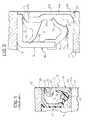
- Figure 2 is a partial axial cross-sectional view of a sealing device according to the present invention, mounted in a bearing.
- With reference to Figure 2, and using the same reference numbers already used to indicate same or similar parts discussed with reference to Figure 1, a
gasket 16 of elastomeric material having a substantially V-shaped cross-section is fixed to a metallicannular shield 15 secured to an outer,rotatable race 12 of a bearing. An annular metallic shield (or flinger) 14 is fixed to the innerstationary race 13 of the bearing.Shield 14 has a substantially L-shaped cross section with a cylindricalaxial portion 19 fixed to a coaxial,cylindrical surface 13a ofinner race 13, and aradial wall portion 20 extending towards theouter race 12 of the bearing. - The
gasket 16 forms aradial sealing lip 17 intended to radially contact thecylindrical portion 19 ofshield 14. Further, thegasket 16 forms an elongatedaxial sealing lip 18 for elastically contacting theradial wall 20 ofshield 14. - According to the present invention, over-moulded or vulcanized onto the
shield 14 is anannular gasket 22 forming, as a single piece: - a radially
outer portion 22a with a first,radial sealing lip 23 sliding against an axialcylindrical portion 25 of theopposite shield 15, and a second,axial sealing lip 24 sliding against aradial wall portion 26 ofshield 15; - a radially
inner portion 22b with a further,static sealing lip 28 projecting in a radially inner direction so as to seal from the outside the interface zone between theaxial portion 19 ofshield 14 and theinner race 13; - a covering
layer 22c joining theportions radial surface 14a of theflinger 14 on a side facing the outside of the bearing. - It is to be noted that in figure 2, the
gaskets - Owing to this shape, the
gasket 22 achieves the following advantages. - The
static sealing lip 28, formed as a single piece with thegasket 22, allows to eliminate the conventional rubber film indicated 29 in Figure 1. This simplifies and accelerates the step of assembling the sealing device in the bearing and eliminates costs related to the manufacturing of the said film. - The covering
layer 22c allows to use aflinger 14 made of a material different from stainless steel, conventionally used. For example, a cheaper and non-inoxidable metal may be used, which will be protected by thelayer 22c anyway. - By selecting a non-inoxidable material for the
flinger 14, for example a non-stainless steel, adhesion of the rubber ofgasket 22 to the flinger is improved. This increases the useful life, the efficiency and reliability of the sealing device. - Possible rubber flashes resulting from vulcanizing the
gasket 22 on theflinger 14 will be in a position (indicated at 27 in Figure 2) non visible from the outside. Therefore, the amount of production waste will be cut down drastically as compared to the past. - The
axial sealing lip 24 is optional. However, this lip forms an additional barrier that hinders considerably the access of external contaminating agents to the inner parts of the bearing. - The invention is not intended to be limited to the embodiment described and illustrated herein, which should be considered as an example of an embodiment of the sealing device; rather, the invention may be modified with regard to the shape, dimensions and arrangement of parts, and to constructional and functional details and materials being used. For example, the thickness of the covering
layer 22c may vary locally, for instance forming a number of small seats or notches (not shown) on the outer surface in order to facilitate gripping the gasket by means of mechanical tool used for fitting the sealing device between the races of the bearing.
Claims (4)
- A sealing device (10) for sealing an annular gap (11) between the races (12, 13) of a bearing for the hub of a motor vehicle wheel, particularly a heavy motor vehicle, the sealing device (10) comprising:- a first sealing gasket (16) of elastic material fixed to a first annular shield (15) secured to a first bearing race (12), and- a second annular shield (14) secured to a second bearing race (13), wherein the second annular shield (14) has a substantially L-shaped transversal cross-section with- an axial cylindrical portion (19) adapted for fixing to a cylindrical axial surface (13a) of the second race (13), and- a radial wall (20) extending from the axial cylindrical portion (19) towards the first bearing race (12),- a second sealing gasket (22) of elastic material over-moulded or vulcanized on the second annular shield (14) and having at least one radial sealing lip (23) for contacting an axial cylindrical surface (25) of the first annular shield (15),characterized in that the second gasket (22) forms, as a single piece:a radially outer portion (22a) having said radial sealing lip (23), anda covering layer (22c) that covers continuously on the outside a radial surface (14a) of the second shield (14) on a side facing the outside of the bearing.
- The sealing device of claim 1, characterised in that the covering layer (22c) joins the radially outer portion (22a) to a radially inner portion (22b) having a further, static sealing lip (28) projecting in a radially inner and axially outer direction so as to seal from the outside an interface zone between the axial cylindrical portion (19) of the second shield (14) and the axial cylindrical surface (13a) of the second race (13).
- The sealing device of claim 1, characterized in that the radially outer portion (22a) further forms a second, axial sealing lip (24) for sliding against a radial wall portion (26) of the first annular shield (15).
- The sealing device of any one of the preceding claims, characterized in that the second annular shield (14) is made of a material different from stainless steel, preferably of a non-inoxidable steel or other metal.
Applications Claiming Priority (1)
| Application Number | Priority Date | Filing Date | Title |
|---|---|---|---|
| ITTO20040133 ITTO20040133U1 (en) | 2004-10-20 | 2004-10-20 | HOLDING DEVICE FOR BEARINGS |
Publications (1)
| Publication Number | Publication Date |
|---|---|
| EP1650480A1 true EP1650480A1 (en) | 2006-04-26 |
Family
ID=35429374
Family Applications (1)
| Application Number | Title | Priority Date | Filing Date |
|---|---|---|---|
| EP05109678A Withdrawn EP1650480A1 (en) | 2004-10-20 | 2005-10-18 | A sealing device for bearings |
Country Status (2)
| Country | Link |
|---|---|
| EP (1) | EP1650480A1 (en) |
| IT (1) | ITTO20040133U1 (en) |
Cited By (3)
| Publication number | Priority date | Publication date | Assignee | Title |
|---|---|---|---|---|
| EP2085667A1 (en) * | 2006-11-22 | 2009-08-05 | JTEKT Corporation | Sealing device and rolling bearing device |
| EP2093574A1 (en) | 2008-02-19 | 2009-08-26 | Aktiebolaget SKF | A combined rotation sensing and sealing device for bearings |
| GB2459503A (en) * | 2008-04-25 | 2009-10-28 | Pioneer Weston Internat Ltd | Seal assembly comprising inner and outer rings which are rotatable relative to each other and each having annular sealing means |
Citations (7)
| Publication number | Priority date | Publication date | Assignee | Title |
|---|---|---|---|---|
| US5042822A (en) * | 1988-11-17 | 1991-08-27 | Fag Kugelfischer Georg Schafer Kgaa | Seal with two sealing rings |
| US5407213A (en) * | 1991-09-12 | 1995-04-18 | Nsk. Ltd. | Pack seal having passive pulser ring |
| EP0807775A1 (en) * | 1996-05-17 | 1997-11-19 | SKF INDUSTRIE S.p.A. | A seal system for mechanical members coupled for relative rotation |
| EP0902203A1 (en) * | 1997-09-12 | 1999-03-17 | SKF INDUSTRIE S.p.A. | Sealing assembly for a rolling bearing |
| EP0937984A1 (en) | 1998-02-24 | 1999-08-25 | SKF INDUSTRIE S.p.A. | Roller contact bearing with a sealing device and a device for measuring rotation speed |
| EP1008775A2 (en) | 1998-12-11 | 2000-06-14 | SKF INDUSTRIE S.p.A. | A sealing device for bearings |
| US20040169335A1 (en) * | 1997-09-25 | 2004-09-02 | Oldenburg Michael R. | Retrofittable severe duty seal for a shaft |
-
2004
- 2004-10-20 IT ITTO20040133 patent/ITTO20040133U1/en unknown
-
2005
- 2005-10-18 EP EP05109678A patent/EP1650480A1/en not_active Withdrawn
Patent Citations (7)
| Publication number | Priority date | Publication date | Assignee | Title |
|---|---|---|---|---|
| US5042822A (en) * | 1988-11-17 | 1991-08-27 | Fag Kugelfischer Georg Schafer Kgaa | Seal with two sealing rings |
| US5407213A (en) * | 1991-09-12 | 1995-04-18 | Nsk. Ltd. | Pack seal having passive pulser ring |
| EP0807775A1 (en) * | 1996-05-17 | 1997-11-19 | SKF INDUSTRIE S.p.A. | A seal system for mechanical members coupled for relative rotation |
| EP0902203A1 (en) * | 1997-09-12 | 1999-03-17 | SKF INDUSTRIE S.p.A. | Sealing assembly for a rolling bearing |
| US20040169335A1 (en) * | 1997-09-25 | 2004-09-02 | Oldenburg Michael R. | Retrofittable severe duty seal for a shaft |
| EP0937984A1 (en) | 1998-02-24 | 1999-08-25 | SKF INDUSTRIE S.p.A. | Roller contact bearing with a sealing device and a device for measuring rotation speed |
| EP1008775A2 (en) | 1998-12-11 | 2000-06-14 | SKF INDUSTRIE S.p.A. | A sealing device for bearings |
Cited By (5)
| Publication number | Priority date | Publication date | Assignee | Title |
|---|---|---|---|---|
| EP2085667A1 (en) * | 2006-11-22 | 2009-08-05 | JTEKT Corporation | Sealing device and rolling bearing device |
| EP2085667A4 (en) * | 2006-11-22 | 2011-05-18 | Jtekt Corp | Sealing device and rolling bearing device |
| US8366324B2 (en) | 2006-11-22 | 2013-02-05 | Jtekt Corporation | Sealing device and rolling bearing apparatus |
| EP2093574A1 (en) | 2008-02-19 | 2009-08-26 | Aktiebolaget SKF | A combined rotation sensing and sealing device for bearings |
| GB2459503A (en) * | 2008-04-25 | 2009-10-28 | Pioneer Weston Internat Ltd | Seal assembly comprising inner and outer rings which are rotatable relative to each other and each having annular sealing means |
Also Published As
| Publication number | Publication date |
|---|---|
| ITTO20040133U1 (en) | 2005-01-20 |
Similar Documents
| Publication | Publication Date | Title |
|---|---|---|
| US7658386B2 (en) | Retrofittable severe duty seal for a shaft | |
| US7159871B2 (en) | Retrofittable severe duty seal for a shaft | |
| US4799808A (en) | Compact seal | |
| US6315296B1 (en) | Flangeless retrofittable severe duty seal for a shaft | |
| KR101195665B1 (en) | Sealing device | |
| EP3336395B1 (en) | Sealing device | |
| WO2010061688A1 (en) | Sealing device | |
| EP1108171B1 (en) | Bi-modulus composite seal and its method of manufacture | |
| CN112901663B (en) | Sealing device | |
| US8534674B2 (en) | Unitized radial fluid seal | |
| EP3012475A1 (en) | Hub-bearing unit with a sealing device | |
| JP2000509791A (en) | Sealing device for bearing structure and structure for sealing bearing device | |
| CN113939663B (en) | Sealing device | |
| EP0844420A1 (en) | Unitary oil seal assembly | |
| WO2007108018A1 (en) | Annular sealing assembly, in particular for wheel hubs | |
| US9464720B2 (en) | Annular sealing assembly, in particular for wheel hubs | |
| US7314219B1 (en) | Shaft seal assembly | |
| AU2015218553A1 (en) | A vent plug for a hubcap and method of manufacturing the same | |
| CN112277529A (en) | Sealing device for hub assembly | |
| US20020175473A1 (en) | Method of using a retrofittable severe duty seal for a shaft | |
| EP1650480A1 (en) | A sealing device for bearings | |
| EP1669619B1 (en) | A sealing unit for the bearing of the hub of a wheel | |
| US5286038A (en) | Unitized seal for heavy duty application | |
| CN214788563U (en) | Rolling bearing unit for wheel support | |
| CN110799766A (en) | Bearing device for wheel |
Legal Events
| Date | Code | Title | Description |
|---|---|---|---|
| PUAI | Public reference made under article 153(3) epc to a published international application that has entered the european phase |
Free format text: ORIGINAL CODE: 0009012 |
|
| AK | Designated contracting states |
Kind code of ref document: A1 Designated state(s): AT BE BG CH CY CZ DE DK EE ES FI FR GB GR HU IE IS IT LI LT LU LV MC NL PL PT RO SE SI SK TR |
|
| AX | Request for extension of the european patent |
Extension state: AL BA HR MK YU |
|
| AKX | Designation fees paid | ||
| REG | Reference to a national code |
Ref country code: DE Ref legal event code: 8566 |
|
| STAA | Information on the status of an ep patent application or granted ep patent |
Free format text: STATUS: THE APPLICATION IS DEEMED TO BE WITHDRAWN |
|
| 18D | Application deemed to be withdrawn |
Effective date: 20061027 |