EP1650467B1 - Schwingungsdämpfer - Google Patents
Schwingungsdämpfer Download PDFInfo
- Publication number
- EP1650467B1 EP1650467B1 EP20050021112 EP05021112A EP1650467B1 EP 1650467 B1 EP1650467 B1 EP 1650467B1 EP 20050021112 EP20050021112 EP 20050021112 EP 05021112 A EP05021112 A EP 05021112A EP 1650467 B1 EP1650467 B1 EP 1650467B1
- Authority
- EP
- European Patent Office
- Prior art keywords
- piston
- fixing means
- piston rod
- nut
- thread
- Prior art date
- Legal status (The legal status is an assumption and is not a legal conclusion. Google has not performed a legal analysis and makes no representation as to the accuracy of the status listed.)
- Active
Links
- 238000000034 method Methods 0.000 claims description 9
- 238000004519 manufacturing process Methods 0.000 claims description 3
- 238000007789 sealing Methods 0.000 description 2
- 239000006096 absorbing agent Substances 0.000 description 1
- 239000000853 adhesive Substances 0.000 description 1
- 230000001070 adhesive effect Effects 0.000 description 1
- 238000010276 construction Methods 0.000 description 1
- 238000013016 damping Methods 0.000 description 1
- 230000001419 dependent effect Effects 0.000 description 1
- 238000006073 displacement reaction Methods 0.000 description 1
- 230000013011 mating Effects 0.000 description 1
- 238000003825 pressing Methods 0.000 description 1
- 230000035939 shock Effects 0.000 description 1
Images
Classifications
-
- F—MECHANICAL ENGINEERING; LIGHTING; HEATING; WEAPONS; BLASTING
- F16—ENGINEERING ELEMENTS AND UNITS; GENERAL MEASURES FOR PRODUCING AND MAINTAINING EFFECTIVE FUNCTIONING OF MACHINES OR INSTALLATIONS; THERMAL INSULATION IN GENERAL
- F16F—SPRINGS; SHOCK-ABSORBERS; MEANS FOR DAMPING VIBRATION
- F16F9/00—Springs, vibration-dampers, shock-absorbers, or similarly-constructed movement-dampers using a fluid or the equivalent as damping medium
- F16F9/32—Details
- F16F9/34—Special valve constructions; Shape or construction of throttling passages
- F16F9/348—Throttling passages in the form of annular discs or other plate-like elements which may or may not have a spring action, operating in opposite directions or singly, e.g. annular discs positioned on top of the valve or piston body
-
- F—MECHANICAL ENGINEERING; LIGHTING; HEATING; WEAPONS; BLASTING
- F16—ENGINEERING ELEMENTS AND UNITS; GENERAL MEASURES FOR PRODUCING AND MAINTAINING EFFECTIVE FUNCTIONING OF MACHINES OR INSTALLATIONS; THERMAL INSULATION IN GENERAL
- F16F—SPRINGS; SHOCK-ABSORBERS; MEANS FOR DAMPING VIBRATION
- F16F9/00—Springs, vibration-dampers, shock-absorbers, or similarly-constructed movement-dampers using a fluid or the equivalent as damping medium
- F16F9/32—Details
- F16F9/3207—Constructional features
- F16F9/3228—Constructional features of connections between pistons and piston rods
-
- F—MECHANICAL ENGINEERING; LIGHTING; HEATING; WEAPONS; BLASTING
- F16—ENGINEERING ELEMENTS AND UNITS; GENERAL MEASURES FOR PRODUCING AND MAINTAINING EFFECTIVE FUNCTIONING OF MACHINES OR INSTALLATIONS; THERMAL INSULATION IN GENERAL
- F16F—SPRINGS; SHOCK-ABSORBERS; MEANS FOR DAMPING VIBRATION
- F16F2222/00—Special physical effects, e.g. nature of damping effects
- F16F2222/06—Magnetic or electromagnetic
Definitions
- the invention relates to a vibration damper according to the preamble of patent claim 1.
- a vibration damper comprises an axially movable piston rod to which a piston is attached. On the piston rod, a stop surface is carried out, on which the piston is axially supported. A piston nut fixes the piston, with a fastening thread between the piston rod and the piston nut.
- the damping force of the vibration damper is dependent on the displacement movement of the piston and the piston rod. If the case occurs that the piston detaches from the piston rod, then that would have significant consequences for driving safety. Therefore, numerous methods for securing the piston on the piston rod are known. Very often, the thread is provided with an effective as an adhesive curable plastic. An alternative method is in the DE 34 29 473 A1 described. There are deliberately made different thread sizes on the piston rod and the piston nut, bring the significantly higher frictional forces in the threads with it and thereby prevent the risk of loosening the piston nut automatically.
- the US 3,222,771 discloses a method for producing a positive connection in which an annular fastening element is deformed by means of magnetic force on a profiled component.
- Object of the present invention is to realize a piston lock for a piston nut on a piston rod, on the one hand easy to manufacture, but if necessary, can be solved again.
- the object is achieved in that the piston of the piston assembly is fixed by means of a piston nut on a mounting thread of the piston rod and the annular fastening means of the piston nut is additionally assigned, wherein on the fastening means a radially acting magnetic force F M is exercised, which causes the deformation of the fastening means ,
- a significant advantage compared to a caulking for producing the positive connection is that no tool must be inserted directly into the space of the piston assembly. As a result, there are no special requirements with regard to the positioning of the piston assembly to the magnetic force generating device. It does not matter if the piston rod is positioned a few tenths of a millimeter or not. With a caulking tool, such tolerance ranges are no longer acceptable.
- the piston rod can be provided in addition to the fastening thread with at least one axially extending groove, which forms a positive connection with the fastening means.
- annular attachment means can be biased axially against the piston nut.
- one of the contact surfaces between the piston nut and the fastening means can be provided with a profiling in which volume fractions of the respective other contact component are displaced.
- At least one valve disc of the piston assembly can be biased by a spring which is supported on a spring plate which is fixed by a radially acting magnetic force on the piston rod. This makes it possible to adjust the spring force of the spring stepless.
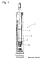
- 1 shows a known per se from the prior art vibration damper 1, which has a piston rod 3 with a piston assembly. 5 has, which is arranged axially displaceable as a structural unit within a cylinder 7. A piston of the piston assembly 5 is axially fixed by a piston nut 10 on the piston rod 3.
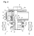
- the piston 9 has a stop plate 11 for a number of valve disks 13, which influence the flow through at least one flow channel 15. Furthermore, an orifice plate 17 is attached, which determines the effective cross section of the at least one flow channel 15.
- This layered part assembly is axially fixed by the piston nut 10 by a mounting thread 19 of the piston rod is in engagement with a mating thread 21 of the piston nut.
- the piston nut has a section with wrench surfaces 23. This section is adjoined by a guide section 25 which, on its lateral surface, guides a sealing ring 27 in conjunction with a support ring 29.
- the support ring is clamped by a spring 31 in conjunction with a spring plate 33 against a Vorö Maschinenside 35.
- the Vorö Maschinenside can move together with the sealing ring 27 and the support ring along the guide portion against the force of the spring 31 when a corresponding pressure in the flow channel 15 is present.
- the length of the guide portion is greater than the maximum Abhubweg the Vorö Maschinenside 35th
- the stop disc 11, the valve discs 13, the piston 9, the throttle disc 17 are threaded onto the pin-shaped end of the piston rod 3.
- the piston is axially against a shoulder 3a of Preloaded piston rod.
- an annular fastener 37 is added to the piston rod 3.
- the fastening means can also be screwed, but can also be pushed without thread with only a very small clearance to the mounting thread 19.
- One of the contact surfaces 39; 41 between the piston nut 10 and the annular attachment means 37, in this embodiment, the piston nut 10 is provided with a profiling 43.
- the region of the piston assembly 5, in which the annular attachment means 37 is arranged is enveloped by a magnetic coil 45, which generates a magnetic field with the radially inwardly directed magnetic force FM.
- the magnetic force FM is so great that a deformation of the entire annular fastening means 37 is effected, which produces a positive connection with the fastening thread 19 of the piston rod.
- the piston rod can still be provided with at least one axially extending groove 47, which enters into a positive connection with the fastening means, which acts against a Losmosotrope the fastener.
- the annular fastening means with the force F A can be biased axially against the piston nut.
- the profiling 43 in the contact surface of the piston nut 10 is filled with displaced volume parts of the annular attachment means 37 during the deformation of the annular attachment means 37, so that there is a further form-locking connection connecting the piston nut 10 with the annular attachment means 37 ,
Landscapes
- Engineering & Computer Science (AREA)
- General Engineering & Computer Science (AREA)
- Mechanical Engineering (AREA)
- Fluid-Damping Devices (AREA)
Description
- Die Erfindung betrifft einen Schwingungsdämpfer gemäß dem Oberbegriff von Patentanspruch 1.
- In der Standardbauweise umfasst ein Schwingungsdämpfer eine axial bewegliche Kolbenstange, an der ein Kolben befestigt wird. An der Kolbenstange ist eine Anschlagfläche ausgeführt, an der sich der Kolben axial abstützt. Eine Kolbenmutter fixiert den Kolben, wobei zwischen der Kolbenstange und der Kolbenmutter ein Befestigungsgewinde vorliegt.
- Die Dämpfkraft des Schwingungsdämpfers ist abhängig von der Verdrängerbewegung des Kolbens und der Kolbenstange. Tritt der Fall ein, dass sich der Kolben von der Kolbenstange löst, dann hätte das für die Fahrsicherheit erhebliche Konsequenzen. Deshalb sind zahlreiche Methoden zur Sicherung des Kolbens auf der Kolbenstange bekannt. Sehr häufig wird das Gewinde mit einem als Klebstoff wirksamen aushärtbare Kunststoff versehen. Eine alternative Methode wird in der
DE 34 29 473 A1 beschrieben. Es werden bewusst voneinander abweichende Gewindeabmessungen an der Kolbenstange und an der Kolbenmutter vorgenommen, die deutlich höhere Reibungskräfte in den Gewindegängen mit sich bringen und dadurch die Gefahr der selbsttätigen Lockerung der Kolbenmutter verhindern. - Ein weitere Methode wird in der
DE 101 61 801 A1 beschrieben. Man drückt ein Verstemmwerkzeug radial in die Kolbenmutter und verdrängt kleine Volumenanteile der Kolbenmutter plastisch in das Befestigungsgewinde der Kolbenstange. - Man könnte natürlich auch ganz auf ein Befestigungsgewinde verzichten und entsprechend der
DE 198 55 974 C1 anstelle einer Kolbenmutter einen Schließring verwenden, der durch ein Umformwerkzeug in ein Rillenprofil der Kolbenstange plastisch verformt wird, wodurch sich die gesamte Problematik gar nicht erst auftreten würde. Das Rillenprofil der Kolbenstange muss eine bestimmte Mindesttiefe aufweisen. Insbesondere bei Kolbenstangen mit einem sehr kleinen Durchmesser wird dann jedoch u. U. ein tragender Querschnitt erreicht, der an die Grenze der Bauteilfestigkeit reicht. - Die
US 3 222 771 offenbart ein Verfahren zur Herstellung einer Formschlussverbindung, in dem ein ringförmiges Befestigungselement mittels Magnetkraft auf ein profiliertes Bauteil verformt wird. - Aufgabe der vorliegenden Erfindung ist es, eine Kolbensicherung für eine Kolbenmutter an einer Kolbenstange zu realisieren, die einerseits leicht herstellbar, aber bei Bedarf auch wieder gelöst werden kann.
- Erfindungsgemäß wird die Aufgabe dadurch gelöst, dass der Kolben der Kolbenbaugruppe mittels einer Kolbenmutter auf einem Befestigungsgewinde der Kolbenstange fixiert und das ringförmige Befestigungsmittel der Kolbenmutter zusätzlich beigeordnet wird, wobei auf das Befestigungsmittel eine radial wirkende Magnetkraft FM ausgeübt wird, die die Deformation des Befestigungsmittels bewirkt.
- Ein wesentlicher Vorteil im Vergleich zu einem Verstemmwerkzeug zur Herstellung der Formschlussverbindung besteht darin, dass kein Werkzeug direkt in den Bauraum der Kolbenbaugruppe eingeführt werden muss. Dadurch liegen auch keine besonderen Anforderungen hinsichtlich der Positionierung der Kolbenbaugruppe zu der Magnetkraft erzeugenden Einrichtung vor. Es spielt keine Rolle, ob die Kolbenstange wenige Zehntelmillimeter falsch positioniert ist oder nicht. Bei einem Verstemmwerkzeug sind derartige Toleranzbereiche nicht mehr akzeptabel.
- Man kann eine bereits eingeführte Kolbenbefestigung beibehalten und das Befestigungsmittel als ein Zusatzelement einführen, ohne dass der bisherige Montageablauf vollständig neugeordnet werden muss.
- Die Kolbenstange kann zusätzlich zum Befestigungsgewinde mit mindestens einer axial verlaufenden Nut versehen werden, die mit dem Befestigungsmittel eine Formschlussverbindung eingeht.
- Zusätzlich kann das ringförmige Befestigungsmittel axial gegen die Kolbenmutter vorgespannt werden. Mit dieser Maßnahme soll die Reibung zwischen dem kolbenstangenseitigen Befestigungsgewinde und einem dem Befestigungsmittel, das ebenfalls ein Innengewinde aufweist, gesteigert werden.
- Des weiteren kann eine der Kontaktflächen zwischen der Kolbenmutter und dem Befestigungsmittel mit einer Profilierung versehen werden, in die Volumenanteile des jeweils anderen Kontaktbauteils verdrängt werden. Mit dieser vorteilhaften Ausgestaltung werden die Kolbenmutter und das ringförmige Befestigungsmittel in Umfangsrichtung miteinander verbunden, so dass die Kolbenmutter zusätzlich gegen eine Losdrehbewegung gesichert ist.
- Unabhängig von der Kolbenbefestigung kann mindestens eine Ventilscheibe der Kolbenbaugruppe von einer Feder vorgespannt werden, die sich auf einem Federteller abstützt, der durch eine radial wirkenden Magnetkraft auf der Kolbenstange fixiert wird. Damit ist es möglich, die Federkraft der Feder stufenlos einzustellen.
- Anhand der folgenden Figurenbeschreibung soll die Erfindung näher erläutert werden.
- Es zeigt:
- Fig. 1
- Prinzipieller Aufbau eines Schwingungsdämpfers
- Fig. 2
- Kolben des Schwingungsdämpfers als Einzelteil
- Die Fig. 1 zeigt einen an sich aus dem Stand der Technik bekannten Schwingungsdämpfer 1, der eine Kolbenstange 3 mit einer Kolbenbaugruppe 5 aufweist, die als Baueinheit innerhalb eines Zylinders 7 axial verschiebbar angeordnet ist. Ein Kolben der Kolbenbaugruppe 5 wird von einer Kolbenmutter 10 an der Kolbenstange 3 axial fixiert.
- Die Fig. 2 beschränkt sich auf ein zapfenförmiges Ende der Kolbenstange 3 mit der Kolbenbaugruppe 5. Der Kolben 9 verfügt über eine Anschlagscheibe 11 für eine Anzahl von Ventilscheiben 13, die den Durchfluss durch mindestens einen Strömungskanal 15 beeinflussen. Des weiteren ist eine Drosselscheibe 17 beigefügt, die den wirksamen Querschnitt des mindestens einen Strömungskanals 15 bestimmt. Dieser geschichtete Teileverband wird von der Kolbenmutter 10 axial fixiert, indem ein Befestigungsgewinde 19 der Kolbenstange mit einem Gegengewinde 21 der Kolbenmutter in Eingriff steht. Die Kolbenmutter verfügt über einen Abschnitt mit Schlüsselflächen 23. Diesem Abschnitt schließt sich ein Führungsabschnitt 25 an, der auf seiner Mantelfläche einen Dichtungsring 27 in Verbindung mit einem Stützring 29 führt. Der Stützring wird von einer Feder 31 in Verbindung mit einem Federteller 33 gegen eine Voröffnungsscheibe 35 gespannt. Die Voröffnungsscheibe kann sich zusammen mit dem Dichtungsring 27 und dem Stützring entlang dem Führungsabschnitt gegen die Kraft der Feder 31 bewegen, wenn ein entsprechender Druck im Strömungskanal 15 ansteht. Die Länge des Führungsabschnitts ist größer als der maximale Abhubweg der Voröffnungsscheibe 35.
- Bei der Montage werden die Anschlagscheibe 11, die Ventilscheiben 13, der Kolben 9, die Drosselscheibe 17 auf das zapfenförmige Ende der Kolbenstange 3 gefädelt. In einer Vorrichtung wird der Kolben axial gegen einen Absatz 3a der Kolbenstange vorgespannt. Anschließend schraubt man die Kolbenmutter 10 mit einer definierten Vorspannung gegen den Kolben 5. Danach wird ein ringförmiges Befestigungsmittel 37 auf die Kolbenstange 3 gefügt. Das Befestigungsmittel kann auch geschraubt sein, kann aber auch ohne Gewinde mit nur einem sehr kleinen Spiel zum Befestigungsgewinde 19 aufgeschoben sein . Eine der Kontaktflächen 39; 41 zwischen der Kolbenmutter 10 und dem ringförmigen Befestigungsmittel 37, in diesem Ausführungsbeispiel die Kolbenmutter 10 , ist mit einer Profilierung 43 versehen. Im weiteren Montageablauf wird der Bereich der Kolbenbaugruppe 5, in dem das ringförmigen Befestigungsmittel 37 angeordnet ist, von einer Magnetspule 45 eingehüllt, die ein Magnetfeld mit der nach innen radial gerichteten Magnetkraft FM erzeugt. Die Magnetkraft FM ist so groß, dass eine Deformation des gesamten ringförmigen Befestigungsmittels 37 bewirkt wird, die eine Formschlussverbindung mit dem Befestigungsgewinde 19 der Kolbenstange herstellt. Zusätzlich zum Befestigungsgewinde kann die Kolbenstange noch mit mindestens einer axial verlaufenden Nut 47 versehen sein, die mit dem Befestigungsmittel eine Formschlussverbindung eingeht, die gegen eine Losdrehbewegung des Befestigungsmittels wirkt.
- Gleichzeitig kann das ringförmige Befestigungsmittel mit der Kraft FA axial gegen die Kolbenmutter vorgespannt sein. Im Zusammenhang mit der Magnetkraft FM wird bei der Deformation des ringförmigen Befestigungsmittels 37 die Profilierung 43 in der Kontaktfläche der Kolbenmutter 10 mit verdrängten Volumenteilen des ringförmigen Befestigungsmittels 37 gefüllt, so dass eine weitere Formschlussverbindung vorliegt, die die Kolbenmutter 10 mit dem ringförmigen Befestigungsmittel 37 verbindet.
- Zusätzlich oder unabhängig von der Art der Befestigung des Kolbens 10 kann anstelle einer Einstellmutter als Federteller 33 auch ein ringförmiges Befestigungsmittel 37 eingesetzt werden, das ebenfalls durch eine radial wirkende Magnetkraft FM auf der Kolbenstange 5 fixiert wird.
Claims (5)
- Verfahren zur Herstellung eines Schwingungsdämpfers (1) mit einer Kolbenstange (3), an der eine Kolbenbaugruppe (5) mit einem ringförmigen Befestigungsmittel (37) fixiert wird, indem zwischen dem ringförmigen Befestigungsmittel (37) und der Kolbenstange (3) eine Formschlussverbindung durch eine Deformation des Befestigungsmittels (37) erreicht wird,
dadurch gekennzeichnet,
dass der Kolben (9) der Kolbenbaugruppe (5) mittels einer Kolbenmutter (10) auf einem Befestigungsgewinde (19) der Kolbenstange (3) fixiert und das ringförmige Befestigungsmittel (37) der Kolbenmutter (10) zusätzlich beigeordnet wird, wobei auf das Befestigungsmittel (37) eine radial wirkende Magnetkraft FM ausgeübt wird, die die Deformation des Befestigungsmittels (37) bewirkt. - Verfahren nach Anspruch 1,
dadurch gekennzeichnet,
dass das Befestigungsgewinde (19) mit mindestens einer axial verlaufenden Nut (47) versehen wird, die mit dem Befestigungsmittel (37) eine Formschlussverbindung eingeht. - Verfahren nach Anspruch 2,
dadurch gekennzeichnet,
dass das ringförmige Befestigungsmittel (37) axial gegen die Kolbenmutter (10) vorgespannt wird. - Verfahren nach Anspruch 3,
dadurch gekennzeichnet,
dass eine der Kontaktflächen (39; 41) zwischen der Kolbenmutter (10) und dem Befestigungsmittel (37) mit einer Profilierung (43) versehen wird, in die Volumenanteile des jeweils anderen Kontaktbauteils (39; 41) verdrängt werden. - Verfahren nach Anspruch 1,
dadurch gekennzeichnet,
dass mindestens eine Ventilscheibe (29) der Kolbenbaugruppe (5) von einer Feder (31) vorgespannt wird, die sich auf einem Federteller (33) abstützt, der durch eine radial wirkenden Magnetkraft FM auf der Kolbenstange (3) fixiert wird.
Applications Claiming Priority (1)
| Application Number | Priority Date | Filing Date | Title |
|---|---|---|---|
| DE200410051731 DE102004051731A1 (de) | 2004-10-22 | 2004-10-22 | Schwingungsdämpfer |
Publications (2)
| Publication Number | Publication Date |
|---|---|
| EP1650467A1 EP1650467A1 (de) | 2006-04-26 |
| EP1650467B1 true EP1650467B1 (de) | 2007-11-21 |
Family
ID=35482183
Family Applications (1)
| Application Number | Title | Priority Date | Filing Date |
|---|---|---|---|
| EP20050021112 Active EP1650467B1 (de) | 2004-10-22 | 2005-09-28 | Schwingungsdämpfer |
Country Status (3)
| Country | Link |
|---|---|
| EP (1) | EP1650467B1 (de) |
| DE (2) | DE102004051731A1 (de) |
| ES (1) | ES2296036T3 (de) |
Cited By (1)
| Publication number | Priority date | Publication date | Assignee | Title |
|---|---|---|---|---|
| DE102008032724A1 (de) | 2008-07-11 | 2010-02-04 | Zf Friedrichshafen Ag | Schwingungsdämpfer |
Families Citing this family (6)
| Publication number | Priority date | Publication date | Assignee | Title |
|---|---|---|---|---|
| DE102005028850B3 (de) * | 2005-06-22 | 2006-12-14 | Zf Friedrichshafen Ag | Schwingungsdämpfer |
| DE102007014247B4 (de) * | 2007-03-24 | 2008-10-30 | Zf Friedrichshafen Ag | Schwingungsdämpfer mit einer hubabhängigen Anschlagfeder |
| DE102007030549A1 (de) * | 2007-06-30 | 2009-01-02 | Zf Friedrichshafen Ag | Kolben-Zylinderaggregat |
| DE102015212860A1 (de) * | 2015-07-09 | 2017-01-12 | Suspa Gmbh | Kolben-Vorrichtung, Verfahren zum Herstellen einer derartigen Kolben-Vorrichtung sowie Kolben-Zylinder-Einheit mit einer derartigen Kolben-Vorrichtung |
| DE102021100224B4 (de) | 2021-01-08 | 2023-05-17 | Vibracoustic Se | Anschlagpuffermodul für eine Luftfeder |
| DE102021100226B4 (de) | 2021-01-08 | 2024-08-08 | Vibracoustic Se | Dämpfer für eine Luftfeder |
Family Cites Families (8)
| Publication number | Priority date | Publication date | Assignee | Title |
|---|---|---|---|---|
| US3222771A (en) * | 1964-10-21 | 1965-12-14 | Robert J Schwinghamer | Method of securing objects together by magnetic deformation |
| US3313536A (en) * | 1965-02-01 | 1967-04-11 | Gen Motors Corp | Shock absorber |
| US3590464A (en) * | 1969-03-07 | 1971-07-06 | Gulf Energy & Environ Systems | Threaded fastener and method of making the same |
| DE2948391A1 (de) * | 1979-12-01 | 1981-06-04 | Fichtel & Sachs Ag, 8720 Schweinfurt | Kolben-zylinder-aggregat mit einem im wesentlichen rohrfoermigen behaelter |
| DE3429473A1 (de) * | 1984-08-10 | 1986-02-20 | Fichtel & Sachs Ag, 8720 Schweinfurt | Verschraubungssicherung fuer schwingungsdaempfer und federbeine |
| DE4315458C2 (de) * | 1993-05-10 | 1996-12-05 | Fichtel & Sachs Ag | Ventil für einen hydraulischen Teleskop-Schwingungsdämpfer |
| DE19855974C1 (de) * | 1998-12-04 | 2000-05-18 | Mannesmann Sachs Ag | Befestigung eines Dämpfkolbens auf einer Kolbenstange |
| DE10161801A1 (de) * | 2001-01-08 | 2002-08-29 | Zf Sachs Ag | Kolbenbefestigung |
-
2004
- 2004-10-22 DE DE200410051731 patent/DE102004051731A1/de not_active Withdrawn
-
2005
- 2005-09-28 EP EP20050021112 patent/EP1650467B1/de active Active
- 2005-09-28 ES ES05021112T patent/ES2296036T3/es active Active
- 2005-09-28 DE DE200550002030 patent/DE502005002030D1/de active Active
Cited By (2)
| Publication number | Priority date | Publication date | Assignee | Title |
|---|---|---|---|---|
| DE102008032724A1 (de) | 2008-07-11 | 2010-02-04 | Zf Friedrichshafen Ag | Schwingungsdämpfer |
| DE102008032724B4 (de) * | 2008-07-11 | 2014-03-13 | Zf Friedrichshafen Ag | Schwingungsdämpfer |
Also Published As
| Publication number | Publication date |
|---|---|
| DE102004051731A1 (de) | 2006-05-04 |
| DE502005002030D1 (de) | 2008-01-24 |
| ES2296036T3 (es) | 2008-04-16 |
| EP1650467A1 (de) | 2006-04-26 |
Similar Documents
| Publication | Publication Date | Title |
|---|---|---|
| EP3463998B1 (de) | Pedalkraftsimulatoreinrichtung | |
| EP1869334B1 (de) | Gleitlager, gleitlagersystem und montage eines gleitlagersystems | |
| EP1706302B1 (de) | Hauptzylinder insbesondere für ein geregeltes bremssystem | |
| DE102012102914A1 (de) | Spannvorrichtung für ein Werkstück oder Werkzeug | |
| DE102013215291A1 (de) | Gewindebuchse zum Einschrauben | |
| DE102014100697A1 (de) | Verfahren zum Setzen einer Blindnietmutter mit Toleranzausgleichselement | |
| DE19811917A1 (de) | Kupplungsmechanismus für eine Zahnstange und deren Antriebsritzel | |
| EP1650467B1 (de) | Schwingungsdämpfer | |
| EP1350041B1 (de) | Kolbenbefestigung | |
| WO2005095832A1 (de) | Ventil | |
| DE102013220627B3 (de) | Verfahren zum Befestigen eines Zuganschlags an einer Kolbenstange eines Schwingungsdämpfers | |
| DE102009049920A1 (de) | Spannvorrichtung | |
| DE69212197T2 (de) | Zylinder-Kolben-Stelleinrichtung | |
| DE3010690A1 (de) | Hydraulischer teleskopschwingungsdaempfer mit hydraulischem und elastischem zuganschlag, insbesondere fuer kraftfahrzeuge | |
| EP1332082B1 (de) | Lenkspindelanordnung und ein verfahren zu deren herstellung | |
| EP3580463B1 (de) | Vorrichtung mit einem kolben, einem zylinder und wenigstens einem innenrohr und wenigstens einem aussenrohr | |
| EP1414690A1 (de) | Einrichtung zum verriegeln der endlagen von beweglichen weichenteilen | |
| DE102010063102B4 (de) | Kolbenanordnung für einen Schwingungsdämpfer | |
| AT402541B (de) | Ventil, insbesondere für verdichter | |
| EP4293249A1 (de) | Schwingungstilger mit doppelter masse | |
| EP4033117A1 (de) | Dämpfer für eine luftfeder | |
| DE102022121496A1 (de) | Wälzgewindetrieb und Verfahren zur Auslegung und zum Betrieb eines Wälzgewindetriebs | |
| DE19933971B4 (de) | Drosselelement | |
| DE102005043975A1 (de) | Kolben mit einer gefesselten Feder | |
| DE4034127C2 (de) | Vorrichtung zur Dämpfung von Anschlaggeräuschen von zwei Teilen |
Legal Events
| Date | Code | Title | Description |
|---|---|---|---|
| PUAI | Public reference made under article 153(3) epc to a published international application that has entered the european phase |
Free format text: ORIGINAL CODE: 0009012 |
|
| AK | Designated contracting states |
Kind code of ref document: A1 Designated state(s): AT BE BG CH CY CZ DE DK EE ES FI FR GB GR HU IE IS IT LI LT LU LV MC NL PL PT RO SE SI SK TR |
|
| AX | Request for extension of the european patent |
Extension state: AL BA HR MK YU |
|
| 17P | Request for examination filed |
Effective date: 20060303 |
|
| AKX | Designation fees paid |
Designated state(s): AT BE BG CH CY CZ DE DK EE ES FI FR GB GR HU IE IS IT LI LT LU LV MC NL PL PT RO SE SI SK TR |
|
| GRAP | Despatch of communication of intention to grant a patent |
Free format text: ORIGINAL CODE: EPIDOSNIGR1 |
|
| GRAS | Grant fee paid |
Free format text: ORIGINAL CODE: EPIDOSNIGR3 |
|
| GRAA | (expected) grant |
Free format text: ORIGINAL CODE: 0009210 |
|
| AK | Designated contracting states |
Kind code of ref document: B1 Designated state(s): AT BE BG CH CY CZ DE DK EE ES FI FR GB GR HU IE IS IT LI LT LU LV MC NL PL PT RO SE SI SK TR |
|
| REG | Reference to a national code |
Ref country code: GB Ref legal event code: FG4D Free format text: NOT ENGLISH |
|
| REG | Reference to a national code |
Ref country code: IE Ref legal event code: FG4D Free format text: LANGUAGE OF EP DOCUMENT: GERMAN |
|
| REG | Reference to a national code |
Ref country code: CH Ref legal event code: EP |
|
| REF | Corresponds to: |
Ref document number: 502005002030 Country of ref document: DE Date of ref document: 20080124 Kind code of ref document: P |
|
| REG | Reference to a national code |
Ref country code: ES Ref legal event code: FG2A Ref document number: 2296036 Country of ref document: ES Kind code of ref document: T3 |
|
| PG25 | Lapsed in a contracting state [announced via postgrant information from national office to epo] |
Ref country code: NL Free format text: LAPSE BECAUSE OF FAILURE TO SUBMIT A TRANSLATION OF THE DESCRIPTION OR TO PAY THE FEE WITHIN THE PRESCRIBED TIME-LIMIT Effective date: 20071121 Ref country code: SE Free format text: LAPSE BECAUSE OF FAILURE TO SUBMIT A TRANSLATION OF THE DESCRIPTION OR TO PAY THE FEE WITHIN THE PRESCRIBED TIME-LIMIT Effective date: 20080221 |
|
| NLV1 | Nl: lapsed or annulled due to failure to fulfill the requirements of art. 29p and 29m of the patents act | ||
| PG25 | Lapsed in a contracting state [announced via postgrant information from national office to epo] |
Ref country code: LV Free format text: LAPSE BECAUSE OF FAILURE TO SUBMIT A TRANSLATION OF THE DESCRIPTION OR TO PAY THE FEE WITHIN THE PRESCRIBED TIME-LIMIT Effective date: 20071121 Ref country code: PL Free format text: LAPSE BECAUSE OF FAILURE TO SUBMIT A TRANSLATION OF THE DESCRIPTION OR TO PAY THE FEE WITHIN THE PRESCRIBED TIME-LIMIT Effective date: 20071121 Ref country code: SI Free format text: LAPSE BECAUSE OF FAILURE TO SUBMIT A TRANSLATION OF THE DESCRIPTION OR TO PAY THE FEE WITHIN THE PRESCRIBED TIME-LIMIT Effective date: 20071121 Ref country code: BG Free format text: LAPSE BECAUSE OF FAILURE TO SUBMIT A TRANSLATION OF THE DESCRIPTION OR TO PAY THE FEE WITHIN THE PRESCRIBED TIME-LIMIT Effective date: 20080221 Ref country code: FI Free format text: LAPSE BECAUSE OF FAILURE TO SUBMIT A TRANSLATION OF THE DESCRIPTION OR TO PAY THE FEE WITHIN THE PRESCRIBED TIME-LIMIT Effective date: 20071121 Ref country code: IS Free format text: LAPSE BECAUSE OF FAILURE TO SUBMIT A TRANSLATION OF THE DESCRIPTION OR TO PAY THE FEE WITHIN THE PRESCRIBED TIME-LIMIT Effective date: 20080321 Ref country code: LT Free format text: LAPSE BECAUSE OF FAILURE TO SUBMIT A TRANSLATION OF THE DESCRIPTION OR TO PAY THE FEE WITHIN THE PRESCRIBED TIME-LIMIT Effective date: 20071121 |
|
| GBV | Gb: ep patent (uk) treated as always having been void in accordance with gb section 77(7)/1977 [no translation filed] | ||
| ET | Fr: translation filed | ||
| PG25 | Lapsed in a contracting state [announced via postgrant information from national office to epo] |
Ref country code: DK Free format text: LAPSE BECAUSE OF FAILURE TO SUBMIT A TRANSLATION OF THE DESCRIPTION OR TO PAY THE FEE WITHIN THE PRESCRIBED TIME-LIMIT Effective date: 20071121 Ref country code: CZ Free format text: LAPSE BECAUSE OF FAILURE TO SUBMIT A TRANSLATION OF THE DESCRIPTION OR TO PAY THE FEE WITHIN THE PRESCRIBED TIME-LIMIT Effective date: 20071121 |
|
| PG25 | Lapsed in a contracting state [announced via postgrant information from national office to epo] |
Ref country code: SK Free format text: LAPSE BECAUSE OF FAILURE TO SUBMIT A TRANSLATION OF THE DESCRIPTION OR TO PAY THE FEE WITHIN THE PRESCRIBED TIME-LIMIT Effective date: 20071121 Ref country code: RO Free format text: LAPSE BECAUSE OF FAILURE TO SUBMIT A TRANSLATION OF THE DESCRIPTION OR TO PAY THE FEE WITHIN THE PRESCRIBED TIME-LIMIT Effective date: 20071121 |
|
| PLBE | No opposition filed within time limit |
Free format text: ORIGINAL CODE: 0009261 |
|
| STAA | Information on the status of an ep patent application or granted ep patent |
Free format text: STATUS: NO OPPOSITION FILED WITHIN TIME LIMIT |
|
| PG25 | Lapsed in a contracting state [announced via postgrant information from national office to epo] |
Ref country code: PT Free format text: LAPSE BECAUSE OF FAILURE TO SUBMIT A TRANSLATION OF THE DESCRIPTION OR TO PAY THE FEE WITHIN THE PRESCRIBED TIME-LIMIT Effective date: 20080421 |
|
| REG | Reference to a national code |
Ref country code: IE Ref legal event code: FD4D |
|
| 26N | No opposition filed |
Effective date: 20080822 |
|
| PG25 | Lapsed in a contracting state [announced via postgrant information from national office to epo] |
Ref country code: IE Free format text: LAPSE BECAUSE OF FAILURE TO SUBMIT A TRANSLATION OF THE DESCRIPTION OR TO PAY THE FEE WITHIN THE PRESCRIBED TIME-LIMIT Effective date: 20071121 |
|
| PG25 | Lapsed in a contracting state [announced via postgrant information from national office to epo] |
Ref country code: GB Free format text: LAPSE BECAUSE OF FAILURE TO SUBMIT A TRANSLATION OF THE DESCRIPTION OR TO PAY THE FEE WITHIN THE PRESCRIBED TIME-LIMIT Effective date: 20071121 |
|
| PG25 | Lapsed in a contracting state [announced via postgrant information from national office to epo] |
Ref country code: GR Free format text: LAPSE BECAUSE OF FAILURE TO SUBMIT A TRANSLATION OF THE DESCRIPTION OR TO PAY THE FEE WITHIN THE PRESCRIBED TIME-LIMIT Effective date: 20080222 |
|
| BERE | Be: lapsed |
Owner name: ZF FRIEDRICHSHAFEN A.G. Effective date: 20080930 |
|
| PG25 | Lapsed in a contracting state [announced via postgrant information from national office to epo] |
Ref country code: MC Free format text: LAPSE BECAUSE OF NON-PAYMENT OF DUE FEES Effective date: 20080930 Ref country code: EE Free format text: LAPSE BECAUSE OF FAILURE TO SUBMIT A TRANSLATION OF THE DESCRIPTION OR TO PAY THE FEE WITHIN THE PRESCRIBED TIME-LIMIT Effective date: 20071121 |
|
| PG25 | Lapsed in a contracting state [announced via postgrant information from national office to epo] |
Ref country code: CY Free format text: LAPSE BECAUSE OF FAILURE TO SUBMIT A TRANSLATION OF THE DESCRIPTION OR TO PAY THE FEE WITHIN THE PRESCRIBED TIME-LIMIT Effective date: 20071121 Ref country code: BE Free format text: LAPSE BECAUSE OF NON-PAYMENT OF DUE FEES Effective date: 20080930 |
|
| PG25 | Lapsed in a contracting state [announced via postgrant information from national office to epo] |
Ref country code: AT Free format text: LAPSE BECAUSE OF NON-PAYMENT OF DUE FEES Effective date: 20080928 |
|
| REG | Reference to a national code |
Ref country code: ES Ref legal event code: FD2A Effective date: 20080929 |
|
| PG25 | Lapsed in a contracting state [announced via postgrant information from national office to epo] |
Ref country code: ES Free format text: LAPSE BECAUSE OF NON-PAYMENT OF DUE FEES Effective date: 20080929 |
|
| REG | Reference to a national code |
Ref country code: CH Ref legal event code: PL |
|
| PG25 | Lapsed in a contracting state [announced via postgrant information from national office to epo] |
Ref country code: HU Free format text: LAPSE BECAUSE OF FAILURE TO SUBMIT A TRANSLATION OF THE DESCRIPTION OR TO PAY THE FEE WITHIN THE PRESCRIBED TIME-LIMIT Effective date: 20080522 Ref country code: LU Free format text: LAPSE BECAUSE OF NON-PAYMENT OF DUE FEES Effective date: 20080928 |
|
| PG25 | Lapsed in a contracting state [announced via postgrant information from national office to epo] |
Ref country code: TR Free format text: LAPSE BECAUSE OF FAILURE TO SUBMIT A TRANSLATION OF THE DESCRIPTION OR TO PAY THE FEE WITHIN THE PRESCRIBED TIME-LIMIT Effective date: 20071121 |
|
| PG25 | Lapsed in a contracting state [announced via postgrant information from national office to epo] |
Ref country code: CH Free format text: LAPSE BECAUSE OF NON-PAYMENT OF DUE FEES Effective date: 20090930 Ref country code: LI Free format text: LAPSE BECAUSE OF NON-PAYMENT OF DUE FEES Effective date: 20090930 |
|
| PGFP | Annual fee paid to national office [announced via postgrant information from national office to epo] |
Ref country code: IT Payment date: 20080930 Year of fee payment: 4 |
|
| PGFP | Annual fee paid to national office [announced via postgrant information from national office to epo] |
Ref country code: FR Payment date: 20130910 Year of fee payment: 9 |
|
| PGFP | Annual fee paid to national office [announced via postgrant information from national office to epo] |
Ref country code: DE Payment date: 20140923 Year of fee payment: 10 |
|
| REG | Reference to a national code |
Ref country code: FR Ref legal event code: ST Effective date: 20150529 |
|
| PG25 | Lapsed in a contracting state [announced via postgrant information from national office to epo] |
Ref country code: FR Free format text: LAPSE BECAUSE OF NON-PAYMENT OF DUE FEES Effective date: 20140930 |
|
| REG | Reference to a national code |
Ref country code: DE Ref legal event code: R119 Ref document number: 502005002030 Country of ref document: DE |
|
| PG25 | Lapsed in a contracting state [announced via postgrant information from national office to epo] |
Ref country code: DE Free format text: LAPSE BECAUSE OF NON-PAYMENT OF DUE FEES Effective date: 20160401 |