EP1650148A2 - Machine d'enroulement - Google Patents
Machine d'enroulement Download PDFInfo
- Publication number
- EP1650148A2 EP1650148A2 EP05109365A EP05109365A EP1650148A2 EP 1650148 A2 EP1650148 A2 EP 1650148A2 EP 05109365 A EP05109365 A EP 05109365A EP 05109365 A EP05109365 A EP 05109365A EP 1650148 A2 EP1650148 A2 EP 1650148A2
- Authority
- EP
- European Patent Office
- Prior art keywords
- winding
- roller
- roll
- winding machine
- spring
- Prior art date
- Legal status (The legal status is an assumption and is not a legal conclusion. Google has not performed a legal analysis and makes no representation as to the accuracy of the status listed.)
- Withdrawn
Links
Images
Classifications
-
- B—PERFORMING OPERATIONS; TRANSPORTING
- B65—CONVEYING; PACKING; STORING; HANDLING THIN OR FILAMENTARY MATERIAL
- B65H—HANDLING THIN OR FILAMENTARY MATERIAL, e.g. SHEETS, WEBS, CABLES
- B65H18/00—Winding webs
- B65H18/02—Supporting web roll
- B65H18/023—Supporting web roll on its outer circumference
- B65H18/025—Parallel rollers type
-
- B—PERFORMING OPERATIONS; TRANSPORTING
- B65—CONVEYING; PACKING; STORING; HANDLING THIN OR FILAMENTARY MATERIAL
- B65H—HANDLING THIN OR FILAMENTARY MATERIAL, e.g. SHEETS, WEBS, CABLES
- B65H18/00—Winding webs
- B65H18/08—Web-winding mechanisms
- B65H18/14—Mechanisms in which power is applied to web roll, e.g. to effect continuous advancement of web
- B65H18/20—Mechanisms in which power is applied to web roll, e.g. to effect continuous advancement of web the web roll being supported on two parallel rollers at least one of which is driven
-
- B—PERFORMING OPERATIONS; TRANSPORTING
- B65—CONVEYING; PACKING; STORING; HANDLING THIN OR FILAMENTARY MATERIAL
- B65H—HANDLING THIN OR FILAMENTARY MATERIAL, e.g. SHEETS, WEBS, CABLES
- B65H2301/00—Handling processes for sheets or webs
- B65H2301/40—Type of handling process
- B65H2301/41—Winding, unwinding
- B65H2301/413—Supporting web roll
- B65H2301/4137—Supporting web roll on its outer circumference
- B65H2301/41372—Supporting web roll on its outer circumference rollers or balls arrangement
- B65H2301/41376—Supporting web roll on its outer circumference rollers or balls arrangement arranged in a non-stationary manner, i.e. changing according to actual roll diameter
-
- B—PERFORMING OPERATIONS; TRANSPORTING
- B65—CONVEYING; PACKING; STORING; HANDLING THIN OR FILAMENTARY MATERIAL
- B65H—HANDLING THIN OR FILAMENTARY MATERIAL, e.g. SHEETS, WEBS, CABLES
- B65H2301/00—Handling processes for sheets or webs
- B65H2301/40—Type of handling process
- B65H2301/41—Winding, unwinding
- B65H2301/414—Winding
- B65H2301/4148—Winding slitting
-
- B—PERFORMING OPERATIONS; TRANSPORTING
- B65—CONVEYING; PACKING; STORING; HANDLING THIN OR FILAMENTARY MATERIAL
- B65H—HANDLING THIN OR FILAMENTARY MATERIAL, e.g. SHEETS, WEBS, CABLES
- B65H2402/00—Constructional details of the handling apparatus
- B65H2402/30—Supports; Subassemblies; Mountings thereof
-
- B—PERFORMING OPERATIONS; TRANSPORTING
- B65—CONVEYING; PACKING; STORING; HANDLING THIN OR FILAMENTARY MATERIAL
- B65H—HANDLING THIN OR FILAMENTARY MATERIAL, e.g. SHEETS, WEBS, CABLES
- B65H2406/00—Means using fluid
- B65H2406/10—Means using fluid made only for exhausting gaseous medium
- B65H2406/13—Means using fluid made only for exhausting gaseous medium pressure arrangement for compensating weight of handled material
-
- B—PERFORMING OPERATIONS; TRANSPORTING
- B65—CONVEYING; PACKING; STORING; HANDLING THIN OR FILAMENTARY MATERIAL
- B65H—HANDLING THIN OR FILAMENTARY MATERIAL, e.g. SHEETS, WEBS, CABLES
- B65H2511/00—Dimensions; Position; Numbers; Identification; Occurrences
- B65H2511/20—Location in space
- B65H2511/22—Distance
-
- B—PERFORMING OPERATIONS; TRANSPORTING
- B65—CONVEYING; PACKING; STORING; HANDLING THIN OR FILAMENTARY MATERIAL
- B65H—HANDLING THIN OR FILAMENTARY MATERIAL, e.g. SHEETS, WEBS, CABLES
- B65H2515/00—Physical entities not provided for in groups B65H2511/00 or B65H2513/00
- B65H2515/10—Mass, e.g. mass flow rate; Weight; Inertia
-
- B—PERFORMING OPERATIONS; TRANSPORTING
- B65—CONVEYING; PACKING; STORING; HANDLING THIN OR FILAMENTARY MATERIAL
- B65H—HANDLING THIN OR FILAMENTARY MATERIAL, e.g. SHEETS, WEBS, CABLES
- B65H2601/00—Problem to be solved or advantage achieved
- B65H2601/20—Avoiding or preventing undesirable effects
- B65H2601/22—Gravity effects, e.g. effect of weight of handled material
Definitions
- the invention relates to a winding machine for winding a material web, in particular a paper or board web, on at least one winding tube to a winding roll by means of at least one elastically mounted roller on which the winding roll when winding up or rests.
- Material webs must be wound up on shipping or finishing rolls before they can be shipped.
- reel cores usually winding cores are used, which are preferably made of cardboard.
- the finished rolls are produced by so-called mother or spool rolls, which are produced at the exit of a paper machine or after the calendering, unwound, cut in the longitudinal direction and then wound on each winding cores.
- mother or spool rolls which are produced at the exit of a paper machine or after the calendering, unwound, cut in the longitudinal direction and then wound on each winding cores.
- These cores are either on a support roller of a back-up roll winding machine or laterally on this, or the cores are in one of two support rollers of a double carrier roll winding machine formed winding bed.
- a web supported on a support roll is wound on a winding mandrel as it passes through a nip formed between the support roll and the wound roll to be formed, the winding roll being additionally supported by another device comprising two small rolls becomes.
- a back-up roll winding machine either only a single winding roll may be wound or a plurality of winding rolls each held in winding stations by individual tensioning devices, the tensioning devices alternating the winding rolls to both sides from a vertical axis passing through the center of the backing roll hold, wherein the connecting lines between the centers of the bobbins and the support roller are inclined in each case to both sides of the vertical at an acute angle or form a right angle with the vertical.
- the clamping heads and the winding tubes in the winding stations can also have different diameters.
- a support device for rolls wound from webs is known in which at least one of the two support rollers is elastically mounted. Due to the elastic support receives the one support roller with the same design of both rolls a different natural frequency to each other, so that a summation of the vibrations of the two rolls and thus a roll damage is excluded.
- a well-known from DE-AS 23 18 351 carrying device is characterized in that in all the essential parts and with respect to the characteristics of the same springs, the spring systems are arranged asymmetrically with respect to the plane passing through the winding roll axis vertical plane. In this way, the two support rollers associated lines of action are at an angle to each other, so that the vibrations also impinge on the respective suspension system in a different angle or at different locations. As a result, the suspension behavior of the suspension systems of the two support rollers is different, without that therefore the support roller suspension or its storage or the support rollers themselves would have to be designed differently or adjustable.
- This object is achieved in a winding machine of the initially mentioned type achieved in that the axis of the at least one roller is held constant during winding at its positions by a positioning, which compensates for the deflection of the roller due to the changing during winding mass of the winding roll.
- the positioning means comprises an actuator, a spring, a damper and a measuring device in order to determine the position of the support rollers accurately.
- this comprises a control or a regulating device.
- This ensures that the roll center does not change with a change in the spring stiffness and the load.
- an actuator under a resilient element, the compression of the existing of the winding and the at least one roller vibration system and thus its excitation is prevented.
- the geometry of the roll bed thus remains under all circumstances; The roller centers do not change their position with a change in the spring stiffness and the forces introduced by the winding roller.
- control or regulating device has a transducer for measuring the position of the at least one roller.
- Particularly suitable is an embodiment of the winding machine in which the spring stiffness of the spring and / or the damping of the damper is variable.
- springs are used in the form of bending beams or as spiral springs.
- the winding machine is developed so that the at least one roller is equipped with a linear guide or another element with which the at least one roller is displaceable in the direction of the other roller.
- At least one of two rollers is fastened to a rocker, by means of which it is pivotable in the vertical direction or in the direction of the other carrier roller.
- the invention also relates to a method for winding a material web, in particular a paper or board web, roll in a winding machine on a sleeve to a winding center Is at least one elastically mounted roller on which the winding roll when winding up or rests.
- the method according to the invention is characterized in that the axis of the at least one support roller is held constant at its position during winding.
- the entire invention can be used in a double-winder winding machine, but also when only a single roller is used as a support roller for the cut longitudinally paper webs.
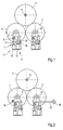
- the individual coils are supported alternately in an eleven o'clock position and in a one o'clock position relative to the back-up roller.
- there is a desire for a constant maintenance of the position of the center of the support roller which is realized by the use of a positioning according to the invention.
- the windings can also be located at other symmetrically opposite positions in the region of the two upper quadrants of the support roller.
- a winding device formed by a double-winder winding machine has two support rollers 1, 2, at least one of which is driven.
- the support rollers 1, 2 form a roller bed, in which several adjacent bobbins 3 rest during winding on the support rollers 1, 2.
- a longitudinal cutting device (not shown), a material web, in particular a paper or board web, is cut into a plurality of individual webs before winding, which are then passed through the gap between the support rollers 1, 2 or laterally around the web Cloak one of the two support rollers 1, 2 are guided around in the roll bed, where they are wound up in aligned rows of sleeves 4.
- the support roller 1 is mounted on a positioning means 6 via a bearing 5, which comprises an actuator 7, a spring 8, a damper 9 and a measuring device 10.
- This generates according to the current position of the support roller 1, a signal that iterergerg the measuring device 10 to the actuator 7, so that this according to a deviation between an actual position and a required desired position of the support roller 1, a piston 11 of a hydraulic or pneumatic Cylinder 12 actuated.
- an electromotive adjusting means such as a pneumatically operated bellows cylinder or a rolling diaphragm can be used.
- the piston 11 in turn presses on the spring 8, and this acts on the support roller 1 a.
- the damper 9 is a vibration energy dissipation element and includes, for example, a cylinder 13 filled with a gas.
- the gas is compressed by a punch 14 connected to the bearing 5. If, as a result of the vibrations of the support roller 1, the bearing 5 passes this to the punch 14, this compresses the gas, and a part of the vibration energy is converted into heat. It is understood that the vibrational energy can be derived in other ways from the system, for example by electrical eddy currents.
- the support roller 2 is mounted on a bearing 15 which, like the bearing 5 of the support roller 1 is mounted.
- the spring stiffness of the spring 8 can be changed.
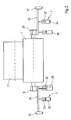
- a linear guide 16 is arranged on the bearing 5 of the support roller 1, by which the height position and / or the horizontal position of the bearing 5 and thus the position of the support roller 1 with respect to the support roller 2 and in Reference to the winding 3 can be adjusted.
- the support roller 2 is mounted on a rocker 17 pivotally mounted about a pivot point 18 to their position with respect to the support roller 1 and the coil. 3 to be able to change.
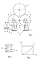
- the actuator 7 comprises on both sides of the shaft of the support roller 1 springs designed as bending beams 19, 20 for elastically supporting the support roller 1, via which bearings 5, 25
- Piston 21, 22 of cylinders 23, 24 act.
- the bending beam 19, 20 press in turn against the bearings 5, 25 of the support rollers 1, 2 and are mounted in brackets 26, 27.
- the rigidity of the bending beams 19, 20 can be changed by changing the position of the cylinders 23, 24 in the direction of the axes of the bending springs 19, 20.
- a damper 28, 29 is also provided in each case.
- a measuring device 30 for determining the position of the support roller 1 is provided.
- the support rollers 1, 2 are mounted on positioning means 31, each comprising a hydraulic cylinder 32 and 33, respectively.
- the cylinder 32 has an oil column 34 whose length is adjustable via a valve 35 from an oil reservoir.
- Throttles 38, 39 are preferably present, via which the speed with which the oil or the air can escape from the interior of the cylinder 32 is set.
- the cylinder 33 is preferably constructed in the same way as illustrated by the example of the cylinder 32.
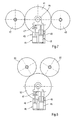
- a back-up roll winding machine ( Figure 7) is shown with a back-up roll 41 against which two bobbins 42, 43 are respectively supported in the nine o'clock position and the three o'clock position.
- the winding rollers 42, 43 are supported by (not shown here) supporting devices and pressed against the jacket of the support roller 41.
- the support roller 41 is mounted on a positioning means 45 via a bearing 44, which, like the positioning means 6, comprises an actuator 46, a spring 47, a damper 48 and a measuring device 49.
- an adjusting or regulating device may be arranged in the backup roll winding machine to adjust the position of the positioning means 45 in accordance with the weight of the winding rolls 40, 41 changing during the winding operation ,
- FIG. 8 another embodiment of a backup roll winding machine is shown, are employed in the winding rollers 50, 51 against a support roller 52. Otherwise, there is a positioning means which has the same construction as the positioning means 45 according to FIG. 7 and is therefore designated by the same reference numerals.
Landscapes
- Winding Of Webs (AREA)
- Replacement Of Web Rolls (AREA)
Applications Claiming Priority (1)
| Application Number | Priority Date | Filing Date | Title |
|---|---|---|---|
| DE200410000033 DE102004000033A1 (de) | 2004-10-21 | 2004-10-21 | Wickelmaschine |
Publications (2)
| Publication Number | Publication Date |
|---|---|
| EP1650148A2 true EP1650148A2 (fr) | 2006-04-26 |
| EP1650148A3 EP1650148A3 (fr) | 2007-11-07 |
Family
ID=35539454
Family Applications (1)
| Application Number | Title | Priority Date | Filing Date |
|---|---|---|---|
| EP05109365A Withdrawn EP1650148A3 (fr) | 2004-10-21 | 2005-10-07 | Machine d'enroulement |
Country Status (2)
| Country | Link |
|---|---|
| EP (1) | EP1650148A3 (fr) |
| DE (1) | DE102004000033A1 (fr) |
Cited By (5)
| Publication number | Priority date | Publication date | Assignee | Title |
|---|---|---|---|---|
| EP1900663A3 (fr) * | 2006-09-18 | 2008-12-24 | Voith Patent GmbH | Bobineuse |
| CN103114489A (zh) * | 2013-01-23 | 2013-05-22 | 福伊特造纸(中国)有限公司 | 网毯校正器 |
| CN104310096A (zh) * | 2014-09-29 | 2015-01-28 | 吴江市欧诚包装材料制品有限公司 | 一种胶带自动压紧复卷机 |
| CN106629163A (zh) * | 2016-11-18 | 2017-05-10 | 无锡祁龙胶粘制品有限公司 | 一种牛皮纸保护膜的收卷装置 |
| CN111705499A (zh) * | 2020-03-23 | 2020-09-25 | 三明市宏立机械制造有限公司 | 一种刀辊调压防跳动装置 |
Families Citing this family (1)
| Publication number | Priority date | Publication date | Assignee | Title |
|---|---|---|---|---|
| FI124595B (fi) * | 2010-10-28 | 2014-10-31 | Valmet Technologies Inc | Kuiturainakoneen telantuentajärjestely ja kuiturainan pituusleikkurin osarainarullain |
Citations (7)
| Publication number | Priority date | Publication date | Assignee | Title |
|---|---|---|---|---|
| DE1245246B (de) * | 1964-08-26 | 1967-07-20 | Keelavite Hydraulics Ltd | Vorrichtung zum Aufwickeln von Materialbahnen |
| US3377033A (en) * | 1966-05-12 | 1968-04-09 | Kimberly Clark Co | Papermaking machine |
| DE2128097A1 (de) * | 1971-06-05 | 1973-01-04 | Voith Gmbh J M | Trageinrichtung fuer aus bahnen aufgewickelte rollen |
| DE2318351B1 (de) * | 1973-04-12 | 1974-07-25 | J.M. Voith Gmbh, 7920 Heidenheim | Trageinrichtung für eine Wickelrolle |
| DE7305837U (de) * | 1973-02-16 | 1974-10-10 | Voith J Gmbh | Trageinrichtung fuer aus bahnen aufgewickelte rollen |
| US4223850A (en) * | 1979-02-28 | 1980-09-23 | Alexander Iii William J | Surface wind batcher and method of collecting material in roll form |
| EP1260470A2 (fr) * | 2001-05-23 | 2002-11-27 | Voith Paper Jagenberg GmbH | Méthode et dispositif pour l'amortissement actif de vibrations dans des enrouleuses |
-
2004
- 2004-10-21 DE DE200410000033 patent/DE102004000033A1/de not_active Withdrawn
-
2005
- 2005-10-07 EP EP05109365A patent/EP1650148A3/fr not_active Withdrawn
Patent Citations (7)
| Publication number | Priority date | Publication date | Assignee | Title |
|---|---|---|---|---|
| DE1245246B (de) * | 1964-08-26 | 1967-07-20 | Keelavite Hydraulics Ltd | Vorrichtung zum Aufwickeln von Materialbahnen |
| US3377033A (en) * | 1966-05-12 | 1968-04-09 | Kimberly Clark Co | Papermaking machine |
| DE2128097A1 (de) * | 1971-06-05 | 1973-01-04 | Voith Gmbh J M | Trageinrichtung fuer aus bahnen aufgewickelte rollen |
| DE7305837U (de) * | 1973-02-16 | 1974-10-10 | Voith J Gmbh | Trageinrichtung fuer aus bahnen aufgewickelte rollen |
| DE2318351B1 (de) * | 1973-04-12 | 1974-07-25 | J.M. Voith Gmbh, 7920 Heidenheim | Trageinrichtung für eine Wickelrolle |
| US4223850A (en) * | 1979-02-28 | 1980-09-23 | Alexander Iii William J | Surface wind batcher and method of collecting material in roll form |
| EP1260470A2 (fr) * | 2001-05-23 | 2002-11-27 | Voith Paper Jagenberg GmbH | Méthode et dispositif pour l'amortissement actif de vibrations dans des enrouleuses |
Cited By (6)
| Publication number | Priority date | Publication date | Assignee | Title |
|---|---|---|---|---|
| EP1900663A3 (fr) * | 2006-09-18 | 2008-12-24 | Voith Patent GmbH | Bobineuse |
| CN103114489A (zh) * | 2013-01-23 | 2013-05-22 | 福伊特造纸(中国)有限公司 | 网毯校正器 |
| CN104310096A (zh) * | 2014-09-29 | 2015-01-28 | 吴江市欧诚包装材料制品有限公司 | 一种胶带自动压紧复卷机 |
| CN106629163A (zh) * | 2016-11-18 | 2017-05-10 | 无锡祁龙胶粘制品有限公司 | 一种牛皮纸保护膜的收卷装置 |
| CN111705499A (zh) * | 2020-03-23 | 2020-09-25 | 三明市宏立机械制造有限公司 | 一种刀辊调压防跳动装置 |
| CN111705499B (zh) * | 2020-03-23 | 2021-12-03 | 三明市宏立机械制造有限公司 | 一种刀辊调压防跳动装置 |
Also Published As
| Publication number | Publication date |
|---|---|
| DE102004000033A1 (de) | 2006-04-27 |
| EP1650148A3 (fr) | 2007-11-07 |
Similar Documents
| Publication | Publication Date | Title |
|---|---|---|
| DE19629205A1 (de) | Verfahren und Vorrichtung zum Aufwickeln einer Papierbahn zu einer Rolle mit aktiver Schwingungsdämpfung | |
| CH645958A5 (de) | Einrichtung mit einer druckbehandlungs- oder transportwalze. | |
| EP1650148A2 (fr) | Machine d'enroulement | |
| EP0879199A1 (fr) | Rouleau pour enrouleur | |
| DE10125192A1 (de) | Verfahren und Vorrichtung zur aktiven Schwingungsdämpfung bei Wickelmaschinen | |
| EP1739040B1 (fr) | Enrouleuse | |
| DE102006043628A1 (de) | Wickelmaschine mit dämpfungsgeregelten Druckwalzen | |
| DE2812958C2 (fr) | ||
| EP1900663B1 (fr) | Procédé d'enroulage d'une bande | |
| DE102005000052A1 (de) | Wickelmaschine | |
| DE10250863B4 (de) | Wickelvorrichtung für bahnförmige Materialien, insbesondere Kunststofffolien | |
| EP1683749B1 (fr) | Bobineuse avec cylindres porteurs | |
| EP1818296B1 (fr) | Dispositif d'enroulement de rouleaux | |
| DE102006043649B4 (de) | Wickelmaschine | |
| DE6922014U (de) | Vorrichtung zum entrollen, insbesondere einer papierbahn | |
| DE102006002980A1 (de) | Verfahren und Vorrichtung zur Dämpfung von Schwingungen in einem Aufroller vom Tragwalzentyp | |
| EP1916209A2 (fr) | Bobineuse à deux rouleaux de support destinée à l'embobinage d'une bande de matériau | |
| EP1710182A2 (fr) | Bobineuse à cylindres porteurs | |
| EP1876119B1 (fr) | Dispositif d'enroulement à rouleaux et procédé destiné à enrouler une bande de matériau | |
| DE4201326A1 (de) | Wickelmaschine | |
| EP0340578B1 (fr) | Dispositif pour empêcher l'ondulation d'une feuille continue | |
| AT505474B1 (de) | Hülsenverriegelungsvorrichtung | |
| DE102009055352A1 (de) | Rollenwickelvorrichtung und Verfahren zum Aufwickeln einer Materialbahn | |
| AT509265B1 (de) | Wickelpartie für einen rollenschneider einer faserbahn und verfahren zum modernisieren einer wickelpartie für einen rollenschneider einer faserbahn | |
| DE102009055374A1 (de) | Rollenwickelvorrichtung |
Legal Events
| Date | Code | Title | Description |
|---|---|---|---|
| PUAI | Public reference made under article 153(3) epc to a published international application that has entered the european phase |
Free format text: ORIGINAL CODE: 0009012 |
|
| AK | Designated contracting states |
Kind code of ref document: A2 Designated state(s): AT BE BG CH CY CZ DE DK EE ES FI FR GB GR HU IE IS IT LI LT LU LV MC NL PL PT RO SE SI SK TR |
|
| AX | Request for extension of the european patent |
Extension state: AL BA HR MK YU |
|
| RAP1 | Party data changed (applicant data changed or rights of an application transferred) |
Owner name: VOITH PATENT GMBH |
|
| PUAL | Search report despatched |
Free format text: ORIGINAL CODE: 0009013 |
|
| AK | Designated contracting states |
Kind code of ref document: A3 Designated state(s): AT BE BG CH CY CZ DE DK EE ES FI FR GB GR HU IE IS IT LI LT LU LV MC NL PL PT RO SE SI SK TR |
|
| AX | Request for extension of the european patent |
Extension state: AL BA HR MK YU |
|
| 17P | Request for examination filed |
Effective date: 20080507 |
|
| AKX | Designation fees paid |
Designated state(s): AT DE FI FR IT SE |
|
| 17Q | First examination report despatched |
Effective date: 20081204 |
|
| STAA | Information on the status of an ep patent application or granted ep patent |
Free format text: STATUS: THE APPLICATION HAS BEEN WITHDRAWN |
|
| 18W | Application withdrawn |
Effective date: 20090331 |