EP1649982B1 - Gas combusion-type impact device - Google Patents
Gas combusion-type impact device Download PDFInfo
- Publication number
- EP1649982B1 EP1649982B1 EP04748258A EP04748258A EP1649982B1 EP 1649982 B1 EP1649982 B1 EP 1649982B1 EP 04748258 A EP04748258 A EP 04748258A EP 04748258 A EP04748258 A EP 04748258A EP 1649982 B1 EP1649982 B1 EP 1649982B1
- Authority
- EP
- European Patent Office
- Prior art keywords
- combustion chamber
- gas
- gaseous mixture
- air
- combustion
- Prior art date
- Legal status (The legal status is an assumption and is not a legal conclusion. Google has not performed a legal analysis and makes no representation as to the accuracy of the status listed.)
- Active
Links
- 238000002485 combustion reaction Methods 0.000 claims abstract description 147
- 239000007789 gas Substances 0.000 claims abstract description 75
- 238000002347 injection Methods 0.000 claims abstract description 38
- 239000007924 injection Substances 0.000 claims abstract description 38
- 239000000567 combustion gas Substances 0.000 claims abstract description 27
- 238000011144 upstream manufacturing Methods 0.000 claims abstract description 17
- 239000008246 gaseous mixture Substances 0.000 claims description 76
- 230000004888 barrier function Effects 0.000 claims description 27
- 230000014759 maintenance of location Effects 0.000 claims description 27
- 239000000446 fuel Substances 0.000 description 12
- 238000013019 agitation Methods 0.000 description 4
- 230000015572 biosynthetic process Effects 0.000 description 4
- 230000000903 blocking effect Effects 0.000 description 2
- 238000007599 discharging Methods 0.000 description 2
- 229910000831 Steel Inorganic materials 0.000 description 1
- 238000010276 construction Methods 0.000 description 1
- 230000000694 effects Effects 0.000 description 1
- 239000000203 mixture Substances 0.000 description 1
- 239000010959 steel Substances 0.000 description 1
Images


Classifications
-
- B—PERFORMING OPERATIONS; TRANSPORTING
- B25—HAND TOOLS; PORTABLE POWER-DRIVEN TOOLS; MANIPULATORS
- B25C—HAND-HELD NAILING OR STAPLING TOOLS; MANUALLY OPERATED PORTABLE STAPLING TOOLS
- B25C1/00—Hand-held nailing tools; Nail feeding devices
- B25C1/08—Hand-held nailing tools; Nail feeding devices operated by combustion pressure
Definitions
- the present invention relates to a gas combustion type impact tool, in which a gaseous mixture are formed by mixing a combustible gas and air in a combustion chamber formed on an upper side of a driving cylinder, a driving piston held in the driving cylinder is driven by a pressure of a combustion gas generated by combusting the gaseous mixture in the combustion chamber, and a nail striking operation and the like are carried out.
- a gas combustion type impact tool in which a gaseous mixture are formed by mixing a combustible gas and air in a combustion chamber formed on an upper side of a driving cylinder, a driving piston held in the driving cylinder is driven by a pressure of a combustion gas generated by combusting the gaseous mixture in the combustion chamber, and a nail striking operation and the like are carried out.
- Such an impact tool is known from US 4403722A , which discloses the preamble of claim 1.
- a combustion gas driven nailing machine which is adapted to inject a combustible gas into a sealed combustion chamber and form a gaseous mixture of the combustible gas and air therein, burn the gaseous mixture in the combustion chamber and generate a high-pressure combustion gas therein, exert the high-pressure combustion gas on a driving piston held in a driving cylinder and drive the driving piston with an impact therein, and strike a nail into a steel plate and concrete by a driver coupled to a lower surface of the driving piston.
- a container such as a gas bottle filled with a combustible gas is fixed in the machine, and a battery used as an electric power source for igniting the combustible gas is fixed to the machine.
- the combustion gas driving nailing machine is thus formed as a portable machine. This enables a nail and a pin driving operation to be carried out without being restricted by a power supply source, such as an electric power source and a compressed air supply source.
- a cylinder slidably holding a driving piston therein is provided in the housing.
- a nail striking driver is connected on the lower surface of the driving piston.
- the driver is held and guided in a nail discharge port formed in a nose coupled to a lower portion of the housing.
- an annular combustion chamber is formed.
- This combustion chamber is defined by an annular sleeve forming a circumferential wall of the combustion chamber, an upper wall formed by an upper housing, and an upper end surface of the driving piston.
- a combustion gas formed in this combustion chamber works on the driving piston, so that the driving piston is driven in the driving cylinder.
- an injection nozzle for injecting a combustible gas put in a gas container, such as a cartridge is formed so that the injection nozzle is opened therein.
- a rotary fan used for generating a gaseous mixture of a predetermined air/fuel ratio by mixing the combustible gas injected into the combustion chamber with the air therein is further formed. The rotary fan is rotated by an electric motor, and the combustible gas injected into the combustion chamber and the air existing in advance therein are agitated, the gaseous mixture being thereby formed in the combustion chamber.
- the combustion chamber is further provided therein with an ignition device used to ignite the gaseous mixture generated in the combustion chamber, and burn the gaseous mixture explosively therein.
- the ignition device is usually made of an ignition plug and the like for generating sparks by discharging a high voltage.
- US 4,403,722 relates to a fastener driving tool powered by the gases produced from the combustion of a fuel and air mixture within a confined space.
- the available power is capable of driving fasteners at a rapid rate in a portable tool at an economic basis.
- the document fails to disclose that the tool is provided with a vortex generator for generating a vortex near an injection nozzle in the combustion chamber.
- the present invention aims to provide a gas combustion type impact tool capable of efficiently agitating a combustible gas injected into a combustion chamber and the air in the combustion chamber, and reliably igniting a gaseous mixture in the combustion chamber.
- the gas combustion type impact tool is formed so that the impact tool is driven by a driving piston held in an annular combustion chamber formed at an upper portion of a driving cylinder, and by supplying a combustible gas into the combustion chamber and forming a gaseous mixture of the air and a combustion gas in the combustion chamber, burning the gaseous mixture by igniting the gaseous mixture in the combustion chamber, and exerting a combustion gas pressure, which is generated by this gaseous mixture burning operation, on the driving piston so as to drive the driving piston, wherein an injection nozzle for injecting the combustible gas into the combustion chamber is formed so that the nozzle faces the interior of the combustion chamber, a rotary fan for mixing the combustible gas supplied into the combustion chamber and the air therein being provided, a vortex generator being formed in a portion of the air flow generated in the combustion chamber by the rotary fan which is on an upstream side of the injection nozzle, vortexes being generated in the position close to the injection
- Another gas combustion type impact tool is formed so that the impact tool is driven by a driving piston held in an annular combustion chamber formed at an upper portion of a driving cylinder, and by supplying a combustible gas into the combustion chamber and forming a gaseous mixture of the air and a combustion gas in the combustion chamber, burning the gaseous mixture by igniting the same in the chamber, and exerting a combustion gas pressure, which is generated this gaseous mixture burning operation, on the driving piston so as to drive the same, wherein a rotary fan for use in mixing the combustible gas supplied into the combustion chamber and the air therein with each other is provided, an ignition device adapted to ignite the gaseous mixture formed in the combustion chamber therein, a retention generator being formed in the portion of the air flow formed in the combustion chamber by the rotary fan which is on the downstream side of the ignition device, the retention generator for easily generating a retention of the gaseous mixture formed by the rotary fan near the ignition device by the retention generator.
- Still another gas combustion impact tool is formed so that the impact tool is driven by a driving piston held in an annular combustion chamber formed at an upper portion of a driving cylinder, and by supplying a combustible gas into the combustion chamber and forming a gaseous mixture of the air and a combustion gas in the combustion chamber, burning the gaseous mixture by igniting the same in the combustion chamber, exerting a combustion gas pressure, which is generated by this gaseous mixture burning operation, on the driving piston so as to drive the same, wherein an injection nozzle for injecting the combustible gas into the combustion chamber and an ignition device for igniting the gaseous mixture generated in the combustion chamber are formed so that both the injection nozzle and ignition device face the interior of the combustion chamber, a rotary fan by which the combustible gas supplied into the combustion chamber and the air therein are mixed with each other being formed in the same chamber, a vortex generator being formed in the portion of the air flow generated in the combustion chamber by the rotary fan which is on the upstream side of the
- the vortex generator provided on the upstream side of the injection nozzle and the retention generator provided on the downstream side of the ignition device may be formed by a common vortex and retention generator in the combustion chamber.
- the vortex generator in the portion of the air current generated by the rotary fan in the combustion chamber is formed on the upstream side of the injection nozzle, and the vortexes generated near the injection nozzle in the combustion chamber by the vortex generator so that the agitation of the combustion gas injected into the combustion chamber and the air therein is promoted by the vortexes. Therefore, the agitation of the combustible gas and the air in the combustion chamber can be carried out efficiently. It also becomes possible to quickly carry out the generation of the gaseous mixture at a predetermined air/fuel ratio in the combustion chamber, and quicken the time at which the gaseous mixture can be ignited.
- the retention generator is formed along the portion of the flow of the gaseous mixture generated in the combustion chamber by the rotary fan which is on the downstream side of the ignition device, and renders it easy to collect the gaseous mixture, which is generated by the rotary fan, near the ignition device. Therefore, the air/fuel ratio of the gaseous mixture which is around the ignition device attains a level at which the gaseous mixture can be ignited quickly. Since the gaseous mixture can be ignited quickly, the igniting of the gaseous mixture by a triggering operation can be done in a short period of time after the starting of the supplying of the combustible gas into the combustion chamber.
- the vortex generator is formed on the upstream side of the injection nozzle, and the vortexes are generated near the injection nozzle in the combustion chamber, by which vortexes the agitation of the combustible gas, which is injected into the combustion chamber, and the air therein is promoted.
- the retention generator is formed on the downstream side of the ignition device, and makes it easy to collect the gaseous mixture, which is generated by the rotary fan, near the ignition device, so that the agitation of the combustible gas and air in the combustible chamber can be carried out efficiently.
- the air/fuel ratio of the gaseous mixture around the ignition device quickly attains a level at which the gaseous mixture can be ignited. Therefore, the igniting of the gaseous mixture becomes able to be done more quickly.
- the vortex generator provided on the upstream side of the injection nozzle and the retention generator provided on the downstream side of the ignition device are formed by a common vortex and retention generator in the combustion chamber, the construction of the nailing machine becomes simple, and the reduction of the cost can be attained.
- a reference numeral 1 denotes a combustion gas driven nailing machine (gas combustion type impact tool), 4 a driving cylinder, 5 a driving piston, 10 a combustion chamber, 11 an upper housing, 12 an upper wall, 13 a movable sleeve, 21 an injection nozzle, 24 a rotary fan, 29 an ignition device, 33 a barrier wall member (vortex generator), and 34 a barrier wall member (retention generator).
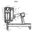
- Fig. 1 shows a combustion gas driven nailing machine representing an embodiment of the gas combustion type impact tool according to the present invention.
- a driving cylinder 4 is held in a housing 2 on which a rearwardly extending grip 3 is formed so as to be integral therewith as shown in Fig. 1 .
- a driving piston 5 to a lower surface of which a nail striking driver 6 is joined is slidably housed.
- a nose 7 having a nail discharge port 8 adapted to guide nails to be guided toward a work is fixed.
- the driver 6 joined to the driving piston 5 is slidably held and guided in the nail discharge port 8 of the nose 7.
- a magazine 9 filled with a plurality of nails is fixed in a connected state, and the nails in the magazine 9 are supplied in order into the nail discharge port 8.
- the nails supplied to the interior of the nail discharge port 8 are struck by the driver 6 and brought out of the nail discharge port 8 into the work.
- a combustion chamber 10 for forming a gaseous mixture of the combustible gas and air and burning this gaseous mixture is formed above the driving cylinder 4, a combustion chamber 10 for forming a gaseous mixture of the combustible gas and air and burning this gaseous mixture is formed.
- the combustion chamber 10 is formed by a movable annular sleeve 13 provided between an upper end portion of the driving cylinder 4 to which an upper end surface of the driving piston 5 is exposed, and an upper wall 12 formed in the interior of an upper housing 11.
- the pressure of the combustion gas generated by forming the gaseous mixture of the combustible gas and air in the combustion chamber 10 and burning the resultant gaseous mixture is exerted on the driving piston 5, which is thereby driven to the position of a bumper 14 provided in a lower dead center in the driving cylinder 4.
- the movable sleeve 13 forming the combustion chamber 10 is provided slidably in the direction of the operation of the driving piston 5.
- the movable sleeve 13 Before the nailing machine 1 is started, the movable sleeve 13 is in a lower position, and communicates with the atmospheric air via an air vent 15 and a passage 16 formed between an outer circumferential surface of the driving cylinder 4 and an inner circumferential surface of the housing 2.
- the movable sleeve 13 is operated to an upper position, and the upper end portion of the movable sleeve 13 is closely engaged with an O-ring 17 provided on the upper wall with the lower end portion of the movable sleeve 13 closely engaged with an O-ring 18 provided on an outer circumference of the driving cylinder 4.
- the interior of the combustion chamber is shut off from the atmospheric air.
- the lower end of the movable sleeve 13 is joined to a link member 19 provided in a space formed between the inner circumferential surface of the housing and the outer circumferential surface of the driving cylinder 4.
- this link member 19 is operated upward, the movable sleeve 13 is moved up, so that the interior of the combustion chamber 10 is shut off from the air vent 15 and passage 16.
- a lower end portion 19a of the link member 19 is provided in the lower portion of the driving cylinder 4 which is above the nose 7.
- the lower end portion 19a of the link member 19 is connected to an upper end portion 20a of a contact member 20 provided so as to project toward a free end of the nail discharge port 8 of the nose 7. Therefore, when the nose 7 of the nailing machine 1 is pressed against the work, the contact member 20 is operated, and the movable sleeve 13 is operated upward via the link member 19, so that the interior of the combustion chamber 10 is shut off from the atmospheric air.
- an injection nozzle 21 facing at a free end portion thereof the interior of the combustion chamber 10 so as to inject the combustible gas into the same chamber 10 is formed.
- a gas supply passage 22 joined to the injection nozzle 21 is connected to a gas container, such as a gas cylinder filled with the combustible gas.
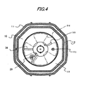
- the upper housing 11 is provided therein with a rotary fan 24 used to generate the gaseous mixture of a predetermined air/fuel ratio in the combustion chamber 10 by agitating the combustible gas injected into the combustion chamber 10 and the air therein.
- the rotary fan 24 has radially provided vanes 26 which are rotated along the circumferential wall of the combustion chamber 10 by an electric motor 25 held in a recess formed in the upper housing 11.
- the air in the combustion chamber 10 is moved along the circumferential wall thereof by rotation of this rotary fan 24, and a circumferential flow of air occurs in the combustion chamber 20.
- the driving of the rotary fan 24 is controlled by a control board 28 provided in an inner portion of a grip 3, in accordance with an operation of a switch 27 actuated with an upward movement of the movable sleeve 13.
- the upper housing 11 is further provided with an ignition device 29 for igniting and burning the gaseous mixture generated in the combustion chamber 10.
- the ignition device 29 is formed by a general ignition plug adapted to generate sparks by increasing a voltage of a battery 30 provided in a rear end portion of the grip 3 to a high level, and discharging the high voltage.
- sparks are generated in the combustion chamber 10 in which the gaseous mixture is formed, the gaseous mixture is ignited and burnt, and a high-pressure combustion gas is generated in the combustion chamber 10.
- the ignition device 29 is driven via the control board 28 on the basis of a switch 32 operated by the trigger 31 formed at a base portion of the grip 3.
- the upper wall 12 of the upper housing 11 forming the combustion chamber 10 is provided with a barrier wall member 33 as a vortex generating means (vortex generator) extending from the center of the combustion chamber 10 in the radially outward direction so as to block a circumferential air flow, which is generated in the combustion chamber 10 by the rotary fan 24, in such a manner that the barrier member 33 is formed on the portion of the upper wall 12 of the upper housing 11 which is on the upstream side of the injection nozzle 21 so as to project from the same upper wall 12 into the interior of the combustion chamber 10.
- a barrier wall member 33 as a vortex generating means (vortex generator) extending from the center of the combustion chamber 10 in the radially outward direction so as to block a circumferential air flow, which is generated in the combustion chamber 10 by the rotary fan 24, in such a manner that the barrier member 33 is formed on the portion of the upper wall 12 of the upper housing 11 which is on the upstream side of the injection nozzle 21 so as to project from the same upper wall 12 into the interior of
- This barrier wall member 33 causes vortexes, which are due to the turbulence of the air flow, to occur in the portion of the interior of the combustion chamber 10 which is on the downstream side of the barrier wall member 33 in which the injection nozzle 21 is formed, and the combustible gas is injected into this portion of this combustion chamber 10 from the injection nozzle 21.
- This combustible gas and air are agitated by fine vortexes efficiently, so that the formation of the gaseous mixture is carried out in a short period of time.
- the upper wall 12 of the upper housing 11 is further provided on the downstream side of the ignition device 29, which extends along the circumferential air flow generated by the rotary fan 24 in the combustion chamber 10, with barrier wall member 34 as a retention generating means (retention generator) extending from the center of the combustion chamber 10 in the radially outward direction so as to block the flow of the gaseous mixture in the combustion chamber 10, the barrier wall member 34 projecting from the surface of the same upper wall 12 of the upper housing into the interior of the combustion chamber 10.
- retention generating means retention generator
- the gaseous mixture just obtained by agitating the combustible gas injected into the combustion chamber and the air therein is collected around the ignition device 29, and the gaseous mixture around the ignition device 29 is set to such an air/fuel ratio that permits the gaseous mixture in the combustion chamber 10 to be ignited reliably.
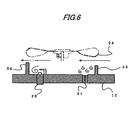
- Fig. 6 shows the annular combustion chamber 10 in development for the convenience of the description thereof.
- the operation of the present invention based on the air flow generated in the combustion chamber 10 by the rotary fan 24 will be described on the basis of what is shown in this drawing.
- the air flow circulating therein as shown by arrows in the drawing is generated.
- a part of the air flow is blocked by the barrier wall member 33 formed on the upstream side of the injection nozzle 21 which is adapted to inject the combustible gas into the combustion chamber 10, and the turbulence of the air flow occurs on the downstream side of the barrier member 33, so that a plurality of fine vortexes occur.
- the combustible gas is injected from the injection nozzle 21 into the vortexes on the downstream side of the barrier wall member 33 in the interior of the combustion chamber 10. Owing to these vortexes of the air, the combustible gas is agitated efficiently. As a result, the formation of an ignitable gaseous mixture is carried out quickly.
- the flow of the gaseous mixture just formed by agitating as mentioned above the combustible gas injected from the injection nozzle 21 into the combustion chamber 10 and the air therein is blocked.
- a gaseous mixture having an air/fuel ratio representing a high concentration of the combustible gas is collected, and the air/fuel ratio of the gaseous mixture around the ignition device is set so that this gaseous mixture can be ignited quickly. As a result, the igniting of the gaseous mixture by the ignition device 29 can be done quickly.
- the barrier wall member 33 for blocking the air flow in the combustion chamber 10 is formed on the upstream side of the injection nozzle, so that a plurality of fine vortexes occur on the downstream side of the barrier wall member 33. Since the combustible gas is injected into these vortexes via the injection nozzle 21, the formation of ignitable gaseous mixture in the combustion chamber 10 can be carried out quickly. Since the barrier wall member 34 for blocking the flow of the gaseous mixture is formed on the downstream side of the ignition device 29, the gaseous mixture just obtained by agitating the combustible gas injected into the combustion chamber 10 and the air therein is collected around the ignition device 29.
- the air/fuel ratio of the gaseous mixture around the ignition device 29 is set to a level which permits the gaseous mixture to be quickly ignitable.
- the igniting of the gaseous mixture by an operation of the trigger 31 can be done in a short period of time after the starting of the supplying of the combustible gas into the combustion chamber 10. Therefore, the operation response of the nailing machine is improved, and a speedy operation can be attained.
- the barrier wall member 33 as the vortex generating means (vortex generator) formed on the upstream side of the injection nozzle 21, and the barrier wall 34 as the retention generating means (retention generator) formed on the upstream side of the ignition device 29 are all formed by barrier wall members having surfaces extending at right angles to the direction of the flow of the air and gaseous mixture.
- the vortex generating means (vortex generator) formed on the upstream side of the injection nozzle 21 can also be practically used even when the vortex generator has a structure (for example, a hole, a columnar member, an air blowout nozzle and the like) other than a barrier wall member as long as the structures can generate vortexes around the combustible gas injected into the combustion chamber 10.
- the retention generating means (retention generator) formed on the downstream side of the ignition device 29 can employ a structure in which the diaphragm for guiding the flow of the gaseous mixture is formed so that the gaseous mixture just obtained by agitating the combustible gas and air is guided to a position around the ignition device 29 instead of the structure having the above-described barrier wall member 34. Even such a diaphragm-employed structure can obtain the same effect.
- the barrier wall member may be formed on the downstream side of the ignition device for the air flow formed in the combustion chamber by the rotary fan and on the upstream side of the injection nozzle. This barrier wall member may thereby be formed so as to have functions of both the vortex generating means (vortex generator) and retention generating means (retention generator).
- the object of enabling the ignition of a gaseous mixture by the ignition device to be carried out quickly by igniting the gaseous mixture of a predetermined air/fuel ratio, which is formed efficiently by agitating the combustible gas and air in the combustion chamber, was met by generating an air flow in the combustion chamber by the rotary fan, and agitating the combustible gas injected into the combustion chamber and the air therein by vortexes generated on the downstream side of the vortex generator which is formed on the upstream side of the injection nozzle.
- the object was also met by forming the retention generator, which is used to make the gaseous mixture collected easily near the ignition device, on the downstream side of the ignition device.
Landscapes
- Engineering & Computer Science (AREA)
- Chemical & Material Sciences (AREA)
- Combustion & Propulsion (AREA)
- Mechanical Engineering (AREA)
- Portable Nailing Machines And Staplers (AREA)
- Air Bags (AREA)
- Mechanical Treatment Of Semiconductor (AREA)
- Pre-Mixing And Non-Premixing Gas Burner (AREA)
- Feeding, Discharge, Calcimining, Fusing, And Gas-Generation Devices (AREA)
- Incineration Of Waste (AREA)
- Solid-Fuel Combustion (AREA)
Applications Claiming Priority (2)
| Application Number | Priority Date | Filing Date | Title |
|---|---|---|---|
| JP2003283663A JP4147403B2 (ja) | 2003-07-31 | 2003-07-31 | ガス燃焼式衝撃工具の燃焼室構造 |
| PCT/JP2004/011280 WO2005011924A1 (ja) | 2003-07-31 | 2004-07-30 | ガス燃焼式衝撃工具 |
Publications (3)
| Publication Number | Publication Date |
|---|---|
| EP1649982A1 EP1649982A1 (en) | 2006-04-26 |
| EP1649982A4 EP1649982A4 (en) | 2007-05-23 |
| EP1649982B1 true EP1649982B1 (en) | 2009-09-16 |
Family
ID=34113815
Family Applications (1)
| Application Number | Title | Priority Date | Filing Date |
|---|---|---|---|
| EP04748258A Active EP1649982B1 (en) | 2003-07-31 | 2004-07-30 | Gas combusion-type impact device |
Country Status (11)
| Country | Link |
|---|---|
| US (1) | US7308996B2 (ja) |
| EP (1) | EP1649982B1 (ja) |
| JP (1) | JP4147403B2 (ja) |
| KR (1) | KR100804894B1 (ja) |
| CN (1) | CN100410023C (ja) |
| AT (1) | ATE442939T1 (ja) |
| AU (1) | AU2004260754B2 (ja) |
| CA (1) | CA2532025C (ja) |
| DE (1) | DE602004023206D1 (ja) |
| TW (1) | TWI267429B (ja) |
| WO (1) | WO2005011924A1 (ja) |
Families Citing this family (10)
| Publication number | Priority date | Publication date | Assignee | Title |
|---|---|---|---|---|
| US7478740B2 (en) * | 2006-06-30 | 2009-01-20 | Illinois Tool Works Inc. | Enhanced fuel passageway and adapter for combustion tool fuel cell |
| JP4446287B2 (ja) * | 2005-02-18 | 2010-04-07 | 日立工機株式会社 | 燃焼式釘打機 |
| JP4930672B2 (ja) * | 2005-08-09 | 2012-05-16 | マックス株式会社 | ガス燃焼式打込み工具のファスナー送り機構 |
| JP5011888B2 (ja) * | 2006-08-22 | 2012-08-29 | マックス株式会社 | ガス燃焼式打込み工具 |
| JP4899840B2 (ja) * | 2006-12-05 | 2012-03-21 | マックス株式会社 | ガス燃焼式打込み工具 |
| JP2008221436A (ja) * | 2007-03-15 | 2008-09-25 | Hitachi Koki Co Ltd | 燃焼式動力工具 |
| JP5070957B2 (ja) * | 2007-06-29 | 2012-11-14 | マックス株式会社 | ガス燃焼式打込み工具 |
| CA2711486C (en) * | 2008-01-04 | 2013-07-30 | Illinois Tool Works Inc. | Combustion chamber and cooling system for fastener-driving tools |
| DE102008000167A1 (de) * | 2008-01-29 | 2009-07-30 | Hilti Aktiengesellschaft | Brennkraftbetriebenes Setzgerät |
| US11338422B2 (en) * | 2018-01-19 | 2022-05-24 | Max Co., Ltd. | Driving tool |
Family Cites Families (18)
| Publication number | Priority date | Publication date | Assignee | Title |
|---|---|---|---|---|
| US4403722A (en) * | 1981-01-22 | 1983-09-13 | Signode Corporation | Combustion gas powered fastener driving tool |
| IN157475B (ja) * | 1981-01-22 | 1986-04-05 | Signode Corp | |
| JPS63207569A (ja) * | 1987-02-20 | 1988-08-26 | 日立工機株式会社 | 内燃式ピストン駆動装置 |
| JP2721685B2 (ja) * | 1988-12-05 | 1998-03-04 | 三菱重工業株式会社 | 火花点火ガスエンジン |
| JPH0325307A (ja) | 1989-06-22 | 1991-02-04 | Fuji Electric Co Ltd | 外光三角方式測距装置 |
| JPH06330775A (ja) * | 1993-05-20 | 1994-11-29 | Tokyo Gas Co Ltd | ガスエンジンの運転安定化装置 |
| US5909836A (en) * | 1997-10-31 | 1999-06-08 | Illinois Tool Works Inc. | Combustion powered tool with combustion chamber lockout |
| US6619527B1 (en) * | 2000-10-10 | 2003-09-16 | Illinois Tool Works Inc. | Combustion powered tool suspension for iron core fan motor |
| US20020144498A1 (en) * | 2001-03-20 | 2002-10-10 | Adams Joseph S. | Combustion chamber system with spool-type pre-combustion chamber |
| JP3969195B2 (ja) * | 2002-06-03 | 2007-09-05 | 日立工機株式会社 | ガス釘打機 |
| US6983871B2 (en) * | 2002-08-09 | 2006-01-10 | Hitachi Koki Co., Ltd. | Combustion-powered nail gun |
| US6755159B1 (en) * | 2003-01-20 | 2004-06-29 | Illinois Tool Works Inc. | Valve mechanisms for elongated combustion chambers |
| JP4039269B2 (ja) * | 2003-02-21 | 2008-01-30 | 日立工機株式会社 | 燃焼式動力工具 |
| US6863045B2 (en) * | 2003-05-23 | 2005-03-08 | Illinois Tool Works Inc. | Combustion apparatus having improved airflow |
| JP4144472B2 (ja) * | 2003-08-11 | 2008-09-03 | 日立工機株式会社 | 燃焼式動力工具 |
| JP4385743B2 (ja) * | 2003-11-27 | 2009-12-16 | 日立工機株式会社 | 燃焼式動力工具 |
| JP4385772B2 (ja) * | 2004-01-16 | 2009-12-16 | 日立工機株式会社 | 燃焼式動力工具 |
| JP4446287B2 (ja) * | 2005-02-18 | 2010-04-07 | 日立工機株式会社 | 燃焼式釘打機 |
-
2003
- 2003-07-31 JP JP2003283663A patent/JP4147403B2/ja not_active Expired - Fee Related
-
2004
- 2004-07-22 TW TW093121899A patent/TWI267429B/zh active
- 2004-07-30 US US10/566,261 patent/US7308996B2/en active Active
- 2004-07-30 AU AU2004260754A patent/AU2004260754B2/en not_active Ceased
- 2004-07-30 KR KR1020067001798A patent/KR100804894B1/ko not_active IP Right Cessation
- 2004-07-30 CN CNB2004800200939A patent/CN100410023C/zh active Active
- 2004-07-30 CA CA002532025A patent/CA2532025C/en not_active Expired - Fee Related
- 2004-07-30 EP EP04748258A patent/EP1649982B1/en active Active
- 2004-07-30 AT AT04748258T patent/ATE442939T1/de not_active IP Right Cessation
- 2004-07-30 WO PCT/JP2004/011280 patent/WO2005011924A1/ja active Application Filing
- 2004-07-30 DE DE602004023206T patent/DE602004023206D1/de active Active
Also Published As
| Publication number | Publication date |
|---|---|
| AU2004260754B2 (en) | 2009-09-17 |
| TW200513355A (en) | 2005-04-16 |
| JP4147403B2 (ja) | 2008-09-10 |
| CN100410023C (zh) | 2008-08-13 |
| CN1822923A (zh) | 2006-08-23 |
| AU2004260754A1 (en) | 2005-02-10 |
| ATE442939T1 (de) | 2009-10-15 |
| EP1649982A1 (en) | 2006-04-26 |
| CA2532025A1 (en) | 2005-02-10 |
| US20060237513A1 (en) | 2006-10-26 |
| DE602004023206D1 (de) | 2009-10-29 |
| KR20060052894A (ko) | 2006-05-19 |
| TWI267429B (en) | 2006-12-01 |
| WO2005011924A1 (ja) | 2005-02-10 |
| CA2532025C (en) | 2009-11-03 |
| EP1649982A4 (en) | 2007-05-23 |
| JP2005046977A (ja) | 2005-02-24 |
| KR100804894B1 (ko) | 2008-02-20 |
| US7308996B2 (en) | 2007-12-18 |
Similar Documents
| Publication | Publication Date | Title |
|---|---|---|
| JP4788228B2 (ja) | ガス燃焼式打込み工具における燃焼室保持機構 | |
| JP4935978B2 (ja) | ガス燃焼式打込み工具における燃焼室のバルブ装置 | |
| EP2161107B1 (en) | Gas combustion type knock tool | |
| JP2007237328A (ja) | 燃焼式動力工具 | |
| EP1649982B1 (en) | Gas combusion-type impact device | |
| US8561867B2 (en) | Gas combustion type fastener driving machine | |
| JP4622437B2 (ja) | 燃焼ガス駆動釘打機の打込み深さ調整装置 | |
| WO2007105572A1 (ja) | ガス燃焼式打込み工具 | |
| TWI267430B (en) | Gas combustion-type impact tool and ignition control method | |
| EP1543926B1 (en) | Combustion chamber arrangement in combustion type power tool | |
| EP1693157B1 (en) | Combustion-type power tool having ignition proof arrangement | |
| US9676089B2 (en) | Combustion-operated setting tool | |
| JP5067095B2 (ja) | ガス燃焼式打込み工具 | |
| JP5045297B2 (ja) | ガス内燃式打込み工具 | |
| JP2019136819A (ja) | 打ち込み工具 | |
| JP2003136424A (ja) | ガス釘打機 | |
| JP2006224270A (ja) | 燃焼式釘打機 |
Legal Events
| Date | Code | Title | Description |
|---|---|---|---|
| PUAI | Public reference made under article 153(3) epc to a published international application that has entered the european phase |
Free format text: ORIGINAL CODE: 0009012 |
|
| 17P | Request for examination filed |
Effective date: 20060118 |
|
| AK | Designated contracting states |
Kind code of ref document: A1 Designated state(s): AT BE BG CH CY CZ DE DK EE ES FI FR GB GR HU IE IT LI LU MC NL PL PT RO SE SI SK TR |
|
| DAX | Request for extension of the european patent (deleted) | ||
| A4 | Supplementary search report drawn up and despatched |
Effective date: 20070420 |
|
| 17Q | First examination report despatched |
Effective date: 20080717 |
|
| GRAP | Despatch of communication of intention to grant a patent |
Free format text: ORIGINAL CODE: EPIDOSNIGR1 |
|
| GRAS | Grant fee paid |
Free format text: ORIGINAL CODE: EPIDOSNIGR3 |
|
| GRAA | (expected) grant |
Free format text: ORIGINAL CODE: 0009210 |
|
| AK | Designated contracting states |
Kind code of ref document: B1 Designated state(s): AT BE BG CH CY CZ DE DK EE ES FI FR GB GR HU IE IT LI LU MC NL PL PT RO SE SI SK TR |
|
| REG | Reference to a national code |
Ref country code: GB Ref legal event code: FG4D |
|
| REG | Reference to a national code |
Ref country code: CH Ref legal event code: EP Ref country code: CH Ref legal event code: NV Representative=s name: BOVARD AG PATENTANWAELTE |
|
| REG | Reference to a national code |
Ref country code: IE Ref legal event code: FG4D |
|
| REF | Corresponds to: |
Ref document number: 602004023206 Country of ref document: DE Date of ref document: 20091029 Kind code of ref document: P |
|
| PG25 | Lapsed in a contracting state [announced via postgrant information from national office to epo] |
Ref country code: FI Free format text: LAPSE BECAUSE OF FAILURE TO SUBMIT A TRANSLATION OF THE DESCRIPTION OR TO PAY THE FEE WITHIN THE PRESCRIBED TIME-LIMIT Effective date: 20090916 Ref country code: SE Free format text: LAPSE BECAUSE OF FAILURE TO SUBMIT A TRANSLATION OF THE DESCRIPTION OR TO PAY THE FEE WITHIN THE PRESCRIBED TIME-LIMIT Effective date: 20090916 |
|
| PG25 | Lapsed in a contracting state [announced via postgrant information from national office to epo] |
Ref country code: NL Free format text: LAPSE BECAUSE OF FAILURE TO SUBMIT A TRANSLATION OF THE DESCRIPTION OR TO PAY THE FEE WITHIN THE PRESCRIBED TIME-LIMIT Effective date: 20090916 Ref country code: PL Free format text: LAPSE BECAUSE OF FAILURE TO SUBMIT A TRANSLATION OF THE DESCRIPTION OR TO PAY THE FEE WITHIN THE PRESCRIBED TIME-LIMIT Effective date: 20090916 Ref country code: SI Free format text: LAPSE BECAUSE OF FAILURE TO SUBMIT A TRANSLATION OF THE DESCRIPTION OR TO PAY THE FEE WITHIN THE PRESCRIBED TIME-LIMIT Effective date: 20090916 |
|
| NLV1 | Nl: lapsed or annulled due to failure to fulfill the requirements of art. 29p and 29m of the patents act | ||
| PG25 | Lapsed in a contracting state [announced via postgrant information from national office to epo] |
Ref country code: CY Free format text: LAPSE BECAUSE OF FAILURE TO SUBMIT A TRANSLATION OF THE DESCRIPTION OR TO PAY THE FEE WITHIN THE PRESCRIBED TIME-LIMIT Effective date: 20090916 |
|
| PG25 | Lapsed in a contracting state [announced via postgrant information from national office to epo] |
Ref country code: CZ Free format text: LAPSE BECAUSE OF FAILURE TO SUBMIT A TRANSLATION OF THE DESCRIPTION OR TO PAY THE FEE WITHIN THE PRESCRIBED TIME-LIMIT Effective date: 20090916 Ref country code: ES Free format text: LAPSE BECAUSE OF FAILURE TO SUBMIT A TRANSLATION OF THE DESCRIPTION OR TO PAY THE FEE WITHIN THE PRESCRIBED TIME-LIMIT Effective date: 20091227 Ref country code: EE Free format text: LAPSE BECAUSE OF FAILURE TO SUBMIT A TRANSLATION OF THE DESCRIPTION OR TO PAY THE FEE WITHIN THE PRESCRIBED TIME-LIMIT Effective date: 20090916 Ref country code: PT Free format text: LAPSE BECAUSE OF FAILURE TO SUBMIT A TRANSLATION OF THE DESCRIPTION OR TO PAY THE FEE WITHIN THE PRESCRIBED TIME-LIMIT Effective date: 20100118 Ref country code: RO Free format text: LAPSE BECAUSE OF FAILURE TO SUBMIT A TRANSLATION OF THE DESCRIPTION OR TO PAY THE FEE WITHIN THE PRESCRIBED TIME-LIMIT Effective date: 20090916 |
|
| PG25 | Lapsed in a contracting state [announced via postgrant information from national office to epo] |
Ref country code: SK Free format text: LAPSE BECAUSE OF FAILURE TO SUBMIT A TRANSLATION OF THE DESCRIPTION OR TO PAY THE FEE WITHIN THE PRESCRIBED TIME-LIMIT Effective date: 20090916 |
|
| PG25 | Lapsed in a contracting state [announced via postgrant information from national office to epo] |
Ref country code: BE Free format text: LAPSE BECAUSE OF FAILURE TO SUBMIT A TRANSLATION OF THE DESCRIPTION OR TO PAY THE FEE WITHIN THE PRESCRIBED TIME-LIMIT Effective date: 20090916 Ref country code: AT Free format text: LAPSE BECAUSE OF FAILURE TO SUBMIT A TRANSLATION OF THE DESCRIPTION OR TO PAY THE FEE WITHIN THE PRESCRIBED TIME-LIMIT Effective date: 20090916 |
|
| PLBE | No opposition filed within time limit |
Free format text: ORIGINAL CODE: 0009261 |
|
| STAA | Information on the status of an ep patent application or granted ep patent |
Free format text: STATUS: NO OPPOSITION FILED WITHIN TIME LIMIT |
|
| PG25 | Lapsed in a contracting state [announced via postgrant information from national office to epo] |
Ref country code: DK Free format text: LAPSE BECAUSE OF FAILURE TO SUBMIT A TRANSLATION OF THE DESCRIPTION OR TO PAY THE FEE WITHIN THE PRESCRIBED TIME-LIMIT Effective date: 20090916 |
|
| 26N | No opposition filed |
Effective date: 20100617 |
|
| PG25 | Lapsed in a contracting state [announced via postgrant information from national office to epo] |
Ref country code: GR Free format text: LAPSE BECAUSE OF FAILURE TO SUBMIT A TRANSLATION OF THE DESCRIPTION OR TO PAY THE FEE WITHIN THE PRESCRIBED TIME-LIMIT Effective date: 20091217 |
|
| PG25 | Lapsed in a contracting state [announced via postgrant information from national office to epo] |
Ref country code: MC Free format text: LAPSE BECAUSE OF NON-PAYMENT OF DUE FEES Effective date: 20100731 |
|
| GBPC | Gb: european patent ceased through non-payment of renewal fee |
Effective date: 20100730 |
|
| PG25 | Lapsed in a contracting state [announced via postgrant information from national office to epo] |
Ref country code: IT Free format text: LAPSE BECAUSE OF FAILURE TO SUBMIT A TRANSLATION OF THE DESCRIPTION OR TO PAY THE FEE WITHIN THE PRESCRIBED TIME-LIMIT Effective date: 20090916 |
|
| REG | Reference to a national code |
Ref country code: CH Ref legal event code: PFA Owner name: MAX CO., LTD. Free format text: MAX CO., LTD.#NO. 6-6, NIHONBASHIHAKOZAKICHO#CHUOH-KU TOKYO 103 (JP) -TRANSFER TO- MAX CO., LTD.#NO. 6-6, NIHONBASHIHAKOZAKICHO#CHUOH-KU TOKYO 103 (JP) |
|
| REG | Reference to a national code |
Ref country code: FR Ref legal event code: ST Effective date: 20110331 |
|
| PG25 | Lapsed in a contracting state [announced via postgrant information from national office to epo] |
Ref country code: FR Free format text: LAPSE BECAUSE OF NON-PAYMENT OF DUE FEES Effective date: 20100802 |
|
| PG25 | Lapsed in a contracting state [announced via postgrant information from national office to epo] |
Ref country code: IE Free format text: LAPSE BECAUSE OF NON-PAYMENT OF DUE FEES Effective date: 20100730 Ref country code: GB Free format text: LAPSE BECAUSE OF NON-PAYMENT OF DUE FEES Effective date: 20100730 |
|
| PG25 | Lapsed in a contracting state [announced via postgrant information from national office to epo] |
Ref country code: LU Free format text: LAPSE BECAUSE OF NON-PAYMENT OF DUE FEES Effective date: 20100730 Ref country code: HU Free format text: LAPSE BECAUSE OF FAILURE TO SUBMIT A TRANSLATION OF THE DESCRIPTION OR TO PAY THE FEE WITHIN THE PRESCRIBED TIME-LIMIT Effective date: 20100317 Ref country code: BG Free format text: LAPSE BECAUSE OF FAILURE TO SUBMIT A TRANSLATION OF THE DESCRIPTION OR TO PAY THE FEE WITHIN THE PRESCRIBED TIME-LIMIT Effective date: 20090916 |
|
| PG25 | Lapsed in a contracting state [announced via postgrant information from national office to epo] |
Ref country code: TR Free format text: LAPSE BECAUSE OF FAILURE TO SUBMIT A TRANSLATION OF THE DESCRIPTION OR TO PAY THE FEE WITHIN THE PRESCRIBED TIME-LIMIT Effective date: 20090916 |
|
| PGFP | Annual fee paid to national office [announced via postgrant information from national office to epo] |
Ref country code: DE Payment date: 20220608 Year of fee payment: 19 |
|
| PGFP | Annual fee paid to national office [announced via postgrant information from national office to epo] |
Ref country code: CH Payment date: 20220801 Year of fee payment: 19 |
|
| REG | Reference to a national code |
Ref country code: DE Ref legal event code: R119 Ref document number: 602004023206 Country of ref document: DE |
|
| REG | Reference to a national code |
Ref country code: CH Ref legal event code: PL |
|
| PG25 | Lapsed in a contracting state [announced via postgrant information from national office to epo] |
Ref country code: DE Free format text: LAPSE BECAUSE OF NON-PAYMENT OF DUE FEES Effective date: 20240201 Ref country code: CH Free format text: LAPSE BECAUSE OF NON-PAYMENT OF DUE FEES Effective date: 20230731 |