EP1648661B1 - Impact wrench having an improved anvil to square driver transition - Google Patents
Impact wrench having an improved anvil to square driver transition Download PDFInfo
- Publication number
- EP1648661B1 EP1648661B1 EP04779777.4A EP04779777A EP1648661B1 EP 1648661 B1 EP1648661 B1 EP 1648661B1 EP 04779777 A EP04779777 A EP 04779777A EP 1648661 B1 EP1648661 B1 EP 1648661B1
- Authority
- EP
- European Patent Office
- Prior art keywords
- anvil
- round body
- square head
- square
- improved
- Prior art date
- Legal status (The legal status is an assumption and is not a legal conclusion. Google has not performed a legal analysis and makes no representation as to the accuracy of the status listed.)
- Expired - Lifetime
Links
Images

Classifications
-
- B—PERFORMING OPERATIONS; TRANSPORTING
- B25—HAND TOOLS; PORTABLE POWER-DRIVEN TOOLS; MANIPULATORS
- B25B—TOOLS OR BENCH DEVICES NOT OTHERWISE PROVIDED FOR, FOR FASTENING, CONNECTING, DISENGAGING, OR HOLDING
- B25B23/00—Details of, or accessories for, spanners, wrenches, screwdrivers
- B25B23/0007—Connections or joints between tool parts
- B25B23/0035—Connection means between socket or screwdriver bit and tool
-
- B—PERFORMING OPERATIONS; TRANSPORTING
- B25—HAND TOOLS; PORTABLE POWER-DRIVEN TOOLS; MANIPULATORS
- B25B—TOOLS OR BENCH DEVICES NOT OTHERWISE PROVIDED FOR, FOR FASTENING, CONNECTING, DISENGAGING, OR HOLDING
- B25B15/00—Screwdrivers
- B25B15/001—Screwdrivers characterised by material or shape of the tool bit
-
- B—PERFORMING OPERATIONS; TRANSPORTING
- B25—HAND TOOLS; PORTABLE POWER-DRIVEN TOOLS; MANIPULATORS
- B25B—TOOLS OR BENCH DEVICES NOT OTHERWISE PROVIDED FOR, FOR FASTENING, CONNECTING, DISENGAGING, OR HOLDING
- B25B21/00—Portable power-driven screw or nut setting or loosening tools; Attachments for drilling apparatus serving the same purpose
- B25B21/02—Portable power-driven screw or nut setting or loosening tools; Attachments for drilling apparatus serving the same purpose with means for imparting impact to screwdriver blade or nut socket
Definitions
- the present invention relates to an impact wrench and more particularly to an improved anvil in an impact wrench.
- the traditional design of an anvil for use in an impact wrench includes a round portion that transitions to a square portion.
- the round portion is received within the impact wrench and acts as a bearing journal.
- the square portion is received within an impact socket.
- the transition from the round cross section to the square cross section inherently creates sharp radii within the transition.
- Sharp radii also act as stress concentration zones within the anvil. As the stress builds at these points, the anvil may fail at the sharp radii. This then can contribute to an early failure of the anvil.
- thermo cryogenic treatment can be applied to the anvil during manufacturing.
- this added step increases the overall cost of manufacturing the anvil and does not directly address the problems associated with the sharp radii.
- an anvil comprising the features of claim 1.
- An anvil adapted to be received within an impact wrench comprises a round body and a square head formed at an end of the round body.
- a tapered ramp extends from the round body to the square head.
- a radius is formed in the tapered ramp. The radius is defined by a removal of material in the tapered ramp.
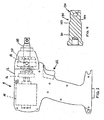
- an exemplary impact wrench 8 is illustrated to include an improved anvil 100 that is constructed in accordance with the teachings of the present invention.
- the impact wrench 8 also includes a housing 12 containing an electric motor 14 whose output is coupled to a gear assembly 16.
- the gear assembly 16 transfers the output to a cam and carrier 18 which in turn drives an impactor 20.
- the improved anvil 100 is mounted within the impactor 20.
- a trigger and handle assembly 22 mounted to the housing 12 is used to activate the electric motor 14.
- a prior art anvil is indicated by reference numeral 10.
- the prior art anvil 10 includes a round body 30 and a square drive head 32.
- a transition zone 34 connects the round body 30 to the square drive head 32, as will be described in greater detail below.
- the round body 30 is generally cylindrical in shape and includes an enlarged base 36 at one end thereof.
- the enlarged base 36 includes two locking wings 38 extending therefrom and adapted to be received within the impactor 20.
- a base radius 40 extends around the circumference of the enlarged base 36 and extends to the round body 30 thereby connecting the two portions.
- the square drive head 32 includes side faces 42 and a front face 44.
- a detente pin hole 46 extends from one of the side faces 42 through the drive head 32.
- the detente pin hole 46 is sized to receive a detente pin, not shown.
- a roll pin hole 48 extends from another side face 42 into the square drive head 32.
- the square drive head 32 is adapted to be inserted into a tool piece, not shown.
- the transition zone 34 includes a tapered ramp 52 extending from the round body 30 to the square drive head 32.
- Sharp radii 54 are formed at the corners of the square drive head 32 where the faces 42 meet the tapered ramp 52. These sharp radii 54 form stress concentration zones and are the sources of potential material failure of the anvil 10.
- the improved anvil 100 includes the round body 30 of the prior art design. However, the improved anvil 100 includes an improved square drive head 132 and an improved transition zone 134.
- the improved square drive head 132 includes side faces 142 and a front face 144.
- a detente pin hole 146 extends from one of the side faces 142 through the improved square drive head 132.
- the detente pin hole 146 is sized to receive a detente pin, not shown.
- a roll pin hole 148 extends from the front face 144 into the improved square drive head 132.
- the roll pin hole 148 is offset from the longitudinal axis of the anvil 100.
- a cutout 149 surrounds the roll pin hole 148 and aids in the removal of the roll pin (not shown) for maintenance purposes.
- the reorientation of the roll pin hole 148 to the front face 144 of the anvil 100 rather than through the side faces 42 decreases the amount of stress applied to the improved square drive head 132, thereby increasing its lifespan.
- the improved square drive head 132 is adapted to receive a tool piece, not shown.
- the transition zone 134 includes a tapered ramp 152 extending from the round body 30 to the improved square improved square drive head 132: It should be understood that the tapered ramp can be eliminated by making the square head and round body of the same general diameter.
- the improved anvil 100 design introduces a removal of material in the transition zone 134 between the round body 30 and improved square drive head 132 of the anvil 100, specifically at the tapered ramp 152. This removal of material forms a radius 154 around the circumference at the tapered ramp 152. As shown in Figure 4 , the cross-sectional area of the anvil 100 at the radius 154 is smaller than the cross-sectional area of the square drive head 132.
- the radius 154 eliminates the sharp radii 54 ( Figure 2 ) seen on the prior art design and eliminates these stress concentration zones and potential sources of failure in the anvil 100.
- the prior art anvil 10 ( Figure 2 ) experiences a load of 975 Mpa of stress on the square drive head 32 through the radii zone 54 when tested under a work load.
- the improved anvil 100 experiences a load of 414 Mpa of stress on the square drive head 132 through the transition zone 134 into the round body 30 when tested under the same work load. Accordingly, the anvil 100 has an improved lifespan over the prior art design ( Figure 2 ).
Landscapes
- Engineering & Computer Science (AREA)
- Mechanical Engineering (AREA)
- Insertion Pins And Rivets (AREA)
- Percussive Tools And Related Accessories (AREA)
Applications Claiming Priority (2)
| Application Number | Priority Date | Filing Date | Title |
|---|---|---|---|
| US10/630,263 US6938526B2 (en) | 2003-07-30 | 2003-07-30 | Impact wrench having an improved anvil to square driver transition |
| PCT/US2004/024825 WO2005011921A1 (en) | 2003-07-30 | 2004-07-30 | Impact wrench having an improved anvil to square driver transition |
Publications (3)
| Publication Number | Publication Date |
|---|---|
| EP1648661A1 EP1648661A1 (en) | 2006-04-26 |
| EP1648661A4 EP1648661A4 (en) | 2010-02-24 |
| EP1648661B1 true EP1648661B1 (en) | 2018-05-30 |
Family
ID=34103803
Family Applications (1)
| Application Number | Title | Priority Date | Filing Date |
|---|---|---|---|
| EP04779777.4A Expired - Lifetime EP1648661B1 (en) | 2003-07-30 | 2004-07-30 | Impact wrench having an improved anvil to square driver transition |
Country Status (5)
| Country | Link |
|---|---|
| US (1) | US6938526B2 (https=) |
| EP (1) | EP1648661B1 (https=) |
| JP (1) | JP4234757B2 (https=) |
| CN (1) | CN1829588B (https=) |
| WO (1) | WO2005011921A1 (https=) |
Families Citing this family (28)
| Publication number | Priority date | Publication date | Assignee | Title |
|---|---|---|---|---|
| USD542109S1 (en) * | 2004-01-02 | 2007-05-08 | Vicmar Solutions, Inc. | Shutter crank extension rod |
| US7207393B2 (en) * | 2004-12-02 | 2007-04-24 | Eastway Fair Company Ltd. | Stepped drive shaft for a power tool |
| US7249638B2 (en) * | 2005-01-07 | 2007-07-31 | Black & Decker Inc. | Impact wrench anvil and method of forming an impact wrench anvil |
| DE102005062777A1 (de) * | 2005-12-28 | 2007-07-05 | Robert Bosch Gmbh | Schlagbolzen für ein Schlagwerk |
| US7726664B2 (en) * | 2005-12-29 | 2010-06-01 | Black & Decker Inc. | Universal tool bit shank |
| US8086460B2 (en) | 2007-06-20 | 2011-12-27 | International Business Machines Corporation | Speech-enabled application that uses web 2.0 concepts to interface with speech engines |
| US7996229B2 (en) | 2007-06-20 | 2011-08-09 | International Business Machines Corporation | System and method for creating and posting voice-based web 2.0 entries via a telephone interface |
| US8041572B2 (en) | 2007-06-20 | 2011-10-18 | International Business Machines Corporation | Speech processing method based upon a representational state transfer (REST) architecture that uses web 2.0 concepts for speech resource interfaces |
| US9311420B2 (en) | 2007-06-20 | 2016-04-12 | International Business Machines Corporation | Customizing web 2.0 application behavior based on relationships between a content creator and a content requester |
| US7890333B2 (en) | 2007-06-20 | 2011-02-15 | International Business Machines Corporation | Using a WIKI editor to create speech-enabled applications |
| US8041573B2 (en) | 2007-06-20 | 2011-10-18 | International Business Machines Corporation | Integrating a voice browser into a Web 2.0 environment |
| US8032379B2 (en) | 2007-06-20 | 2011-10-04 | International Business Machines Corporation | Creating and editing web 2.0 entries including voice enabled ones using a voice only interface |
| US20080319757A1 (en) | 2007-06-20 | 2008-12-25 | International Business Machines Corporation | Speech processing system based upon a representational state transfer (rest) architecture that uses web 2.0 concepts for speech resource interfaces |
| CA2716411C (en) * | 2008-02-27 | 2015-11-24 | Boehringer Ingelheim Microparts Gmbh | Apparatus for the separation of plasma |
| EP2268454B1 (en) * | 2008-03-17 | 2022-09-21 | Stanley Black & Decker, Inc. | Discontinuous drive power tool spindle and socket interface |
| DE112009001116T5 (de) * | 2008-05-07 | 2011-03-17 | Milwaukee Electric Tool Corp., Brookfield | Ambossanordnung für ein Kraftwerkzeug |
| US8631880B2 (en) * | 2009-04-30 | 2014-01-21 | Black & Decker Inc. | Power tool with impact mechanism |
| US8460153B2 (en) | 2009-12-23 | 2013-06-11 | Black & Decker Inc. | Hybrid impact tool with two-speed transmission |
| US8584770B2 (en) | 2010-03-23 | 2013-11-19 | Black & Decker Inc. | Spindle bearing arrangement for a power tool |
| US20130192860A1 (en) | 2011-06-24 | 2013-08-01 | Black & Decker Inc. | Electromagnetic mode change mechanism for power tool |
| US9364942B2 (en) | 2011-06-24 | 2016-06-14 | Black & Decker Inc. | Quick release socket attachment for impact wrench |
| DE102012221906B4 (de) | 2012-11-29 | 2021-12-30 | Robert Bosch Gmbh | Handwerkzeugmaschine mit einer Drehmomentkupplung |
| JP7300345B2 (ja) * | 2019-08-29 | 2023-06-29 | 株式会社マキタ | インパクトレンチ |
| US12036653B2 (en) * | 2020-03-12 | 2024-07-16 | Ingersoll-Rand Industrial U.S., Inc. | Impact tool anvil having a transition region with multiple attributes |
| CN113459024B (zh) * | 2020-03-31 | 2023-06-09 | 喜利得股份公司 | 用于动力工具的套筒保持装置 |
| JP7535905B2 (ja) | 2020-10-13 | 2024-08-19 | 株式会社マキタ | インパクトレンチ |
| CN220051627U (zh) * | 2022-03-09 | 2023-11-21 | 米沃奇电动工具公司 | 冲击工具以及砧 |
| US12528170B2 (en) | 2023-04-25 | 2026-01-20 | Milwaukee Electric Tool Corporation | Impact tool anvil with improved durability |
Family Cites Families (28)
| Publication number | Priority date | Publication date | Assignee | Title |
|---|---|---|---|---|
| US2954994A (en) | 1957-12-23 | 1960-10-04 | Chicago Pneumatic Tool Co | Socket retainer for rotary power tools |
| US3119456A (en) * | 1960-07-05 | 1964-01-28 | Ingersoll Rand Co | Lubrication for pneumatic tools |
| GB1014081A (en) | 1961-01-11 | 1965-12-22 | Maurer S B | Power operated rotary impact tool |
| US3180435A (en) | 1962-05-25 | 1965-04-27 | Chicago Pneumatic Tool Co | Socket retainer for impact wrench |
| DE1603945C3 (de) | 1967-03-28 | 1974-04-04 | Dresser Industries, Inc., Dallas, Tex. (V.St.A.) | Druckluftschlagschrauber |
| US3428137A (en) | 1967-10-12 | 1969-02-18 | Chicago Pneumatic Tool Co | Impact wrench |
| US3605914A (en) | 1968-08-23 | 1971-09-20 | Ingersoll Rand Co | Rotary impact wrench mechanism |
| US3734515A (en) * | 1971-01-29 | 1973-05-22 | Thor Power Tool Co | Power wrench with interchangeable adapters |
| US3890051A (en) | 1974-03-01 | 1975-06-17 | Dresser Ind | Socket retainer for rotatable power tool |
| DE3214842A1 (de) | 1982-04-21 | 1983-10-27 | Wagner, Paul-Heinz, 5203 Much | Drehwerkzeug |
| CN1033168A (zh) * | 1987-11-17 | 1989-05-31 | 莫斯科机械化施工工具和装修机械科研生产联合企业 | 冲击扳手 |
| US4865485A (en) * | 1988-07-05 | 1989-09-12 | Finnefrock Sr James A | Socket extension with safety wedge |
| DE3920471C1 (https=) * | 1989-06-22 | 1990-09-27 | Wagner, Paul-Heinz, 5203 Much, De | |
| US5038869A (en) * | 1989-07-24 | 1991-08-13 | Snap-On Tools Corporation | Fatigue-resistant spindle end |
| DE4402739C2 (de) | 1994-01-28 | 1996-06-20 | Volkswagen Ag | Impulsschrauber |
| US5438894A (en) * | 1994-07-25 | 1995-08-08 | Pearce; Dan C. | Socket wrench extension |
| SE504102C2 (sv) | 1994-12-30 | 1996-11-11 | Atlas Copco Tools Ab | Hydraulisk momentimpulsmekanism avsedd för ett momentavgivande verktyg |
| SE504101C2 (sv) | 1994-12-30 | 1996-11-11 | Atlas Copco Tools Ab | Hydraulisk momentimpulsmekanism |
| EP0747174B1 (en) | 1995-05-30 | 1997-03-26 | Jessie Chow | Coupling mechanism of socket wrench extension |
| USD384563S (en) * | 1996-07-01 | 1997-10-07 | Robinson William A | Socket bit tool |
| SE509915C2 (sv) | 1997-06-09 | 1999-03-22 | Atlas Copco Tools Ab | Hydraulisk momentimpulsgeneratoror |
| DE19859399A1 (de) | 1998-12-23 | 2000-07-06 | Forschungszentrum Juelich Gmbh | Verfahren und Vorrichtung zur quantitativen und qualitativen Bestimmung von Stoffen |
| JP3653205B2 (ja) * | 2000-01-28 | 2005-05-25 | 株式会社マキタ | オイルパルス回転工具 |
| CN2441610Y (zh) * | 2000-10-12 | 2001-08-08 | 上海星特浩企业有限公司 | 旋转式惯力冲击扳手 |
| US6672183B2 (en) * | 2001-04-20 | 2004-01-06 | Theodore L. Johnson | Quick release for use with impact wrench |
| CN1234504C (zh) * | 2001-05-14 | 2006-01-04 | 赖后翔 | 电动冲击扳手 |
| DE20118029U1 (de) | 2001-11-06 | 2002-01-31 | TRANMAX MACHINERY Co., Ltd., Taiping, Taichung | Torsionsbegrenzendes Glied für einen Schlagmechanismus |
| GB2383967A (en) | 2002-01-15 | 2003-07-16 | Tranmax Machinery Co Ltd | A torque restricting mechanism of a pin hammer-type hammering device |
-
2003
- 2003-07-30 US US10/630,263 patent/US6938526B2/en not_active Expired - Lifetime
-
2004
- 2004-07-30 WO PCT/US2004/024825 patent/WO2005011921A1/en not_active Ceased
- 2004-07-30 CN CN2004800219704A patent/CN1829588B/zh not_active Expired - Fee Related
- 2004-07-30 EP EP04779777.4A patent/EP1648661B1/en not_active Expired - Lifetime
- 2004-07-30 JP JP2006522115A patent/JP4234757B2/ja not_active Expired - Fee Related
Non-Patent Citations (1)
| Title |
|---|
| None * |
Also Published As
| Publication number | Publication date |
|---|---|
| US20050022637A1 (en) | 2005-02-03 |
| JP2007500607A (ja) | 2007-01-18 |
| CN1829588A (zh) | 2006-09-06 |
| EP1648661A4 (en) | 2010-02-24 |
| US6938526B2 (en) | 2005-09-06 |
| WO2005011921A1 (en) | 2005-02-10 |
| CN1829588B (zh) | 2012-03-28 |
| EP1648661A1 (en) | 2006-04-26 |
| JP4234757B2 (ja) | 2009-03-04 |
Similar Documents
| Publication | Publication Date | Title |
|---|---|---|
| EP1648661B1 (en) | Impact wrench having an improved anvil to square driver transition | |
| US7036406B2 (en) | Impact wrench having an improved anvil to square driver transition | |
| AU2009244208B2 (en) | Anvil assembly for a power tool | |
| EP1239986B1 (en) | Tool tip and tool body assembly | |
| JP5536163B2 (ja) | ネジ山付留め具のための渦巻型駆動システム | |
| CA2382942A1 (en) | Drill having construction for reducing thrust load in drilling operation, and method of manufacturing the drill | |
| EP2241453A2 (en) | Rolling bearing device for wheels | |
| JPH11173315A (ja) | ねじ及びドライバービットまたはレンチとの組合せ | |
| US6238150B1 (en) | Drilling tool | |
| EP1809911B1 (en) | Fastening element | |
| AU2004239059A1 (en) | Blind fastener and method of removing it from a workpiece | |
| JP2014091212A (ja) | 強度を高めたソケット | |
| US20240149409A1 (en) | Impact tool anvil with friction ring | |
| EP3132903B1 (en) | Drill bit | |
| EP1691087A3 (en) | Frangible Blind Rivet | |
| WO2003031121A1 (en) | Socket wrench for power tool | |
| US12036653B2 (en) | Impact tool anvil having a transition region with multiple attributes | |
| CN113386074B (zh) | 冲击工具 | |
| JP2023089597A (ja) | 回転部材、回転部材の製造方法 | |
| JP4141325B2 (ja) | 深穴切削具 | |
| CN116329449A (zh) | 空气锤锥形垫圈移除工具 | |
| WO2026011276A1 (en) | Impact driver anvil | |
| CN213017339U (zh) | 一种车床传动轴与皮带轮连接装置 | |
| JP2003291014A (ja) | スローアウェイ式ドリル | |
| JP2006247792A (ja) | ねじ締め工具 |
Legal Events
| Date | Code | Title | Description |
|---|---|---|---|
| PUAI | Public reference made under article 153(3) epc to a published international application that has entered the european phase |
Free format text: ORIGINAL CODE: 0009012 |
|
| 17P | Request for examination filed |
Effective date: 20060413 |
|
| RBV | Designated contracting states (corrected) |
Designated state(s): AT BE BG CH CY CZ DE DK EE ES FI FR GB GR HU IE IT LI LU MC NL PL PT RO SE SI SK TR |
|
| DAX | Request for extension of the european patent (deleted) | ||
| A4 | Supplementary search report drawn up and despatched |
Effective date: 20100127 |
|
| RIN1 | Information on inventor provided before grant (corrected) |
Inventor name: KIVETT, BEVERLY Inventor name: DEBELIUS, STEVE Inventor name: MILBOURNE, RODNEY |
|
| 17Q | First examination report despatched |
Effective date: 20101229 |
|
| REG | Reference to a national code |
Ref country code: DE Ref legal event code: R079 Ref document number: 602004052774 Country of ref document: DE Free format text: PREVIOUS MAIN CLASS: B25B0019000000 Ipc: B25B0015000000 |
|
| GRAP | Despatch of communication of intention to grant a patent |
Free format text: ORIGINAL CODE: EPIDOSNIGR1 |
|
| STAA | Information on the status of an ep patent application or granted ep patent |
Free format text: STATUS: GRANT OF PATENT IS INTENDED |
|
| RIC1 | Information provided on ipc code assigned before grant |
Ipc: B25B 23/00 20060101ALI20180131BHEP Ipc: B25B 15/00 20060101AFI20180131BHEP Ipc: B25B 21/02 20060101ALI20180131BHEP |
|
| INTG | Intention to grant announced |
Effective date: 20180215 |
|
| GRAS | Grant fee paid |
Free format text: ORIGINAL CODE: EPIDOSNIGR3 |
|
| GRAA | (expected) grant |
Free format text: ORIGINAL CODE: 0009210 |
|
| STAA | Information on the status of an ep patent application or granted ep patent |
Free format text: STATUS: THE PATENT HAS BEEN GRANTED |
|
| AK | Designated contracting states |
Kind code of ref document: B1 Designated state(s): AT BE BG CH CY CZ DE DK EE ES FI FR GB GR HU IE IT LI LU MC NL PL PT RO SE SI SK TR |
|
| REG | Reference to a national code |
Ref country code: CH Ref legal event code: EP |
|
| REG | Reference to a national code |
Ref country code: AT Ref legal event code: REF Ref document number: 1003131 Country of ref document: AT Kind code of ref document: T Effective date: 20180615 |
|
| REG | Reference to a national code |
Ref country code: IE Ref legal event code: FG4D |
|
| REG | Reference to a national code |
Ref country code: DE Ref legal event code: R096 Ref document number: 602004052774 Country of ref document: DE |
|
| REG | Reference to a national code |
Ref country code: NL Ref legal event code: MP Effective date: 20180530 |
|
| PG25 | Lapsed in a contracting state [announced via postgrant information from national office to epo] |
Ref country code: FI Free format text: LAPSE BECAUSE OF FAILURE TO SUBMIT A TRANSLATION OF THE DESCRIPTION OR TO PAY THE FEE WITHIN THE PRESCRIBED TIME-LIMIT Effective date: 20180530 Ref country code: BG Free format text: LAPSE BECAUSE OF FAILURE TO SUBMIT A TRANSLATION OF THE DESCRIPTION OR TO PAY THE FEE WITHIN THE PRESCRIBED TIME-LIMIT Effective date: 20180830 Ref country code: CY Free format text: LAPSE BECAUSE OF FAILURE TO SUBMIT A TRANSLATION OF THE DESCRIPTION OR TO PAY THE FEE WITHIN THE PRESCRIBED TIME-LIMIT Effective date: 20180530 Ref country code: SE Free format text: LAPSE BECAUSE OF FAILURE TO SUBMIT A TRANSLATION OF THE DESCRIPTION OR TO PAY THE FEE WITHIN THE PRESCRIBED TIME-LIMIT Effective date: 20180530 |
|
| PGFP | Annual fee paid to national office [announced via postgrant information from national office to epo] |
Ref country code: DE Payment date: 20180717 Year of fee payment: 15 |
|
| PG25 | Lapsed in a contracting state [announced via postgrant information from national office to epo] |
Ref country code: GR Free format text: LAPSE BECAUSE OF FAILURE TO SUBMIT A TRANSLATION OF THE DESCRIPTION OR TO PAY THE FEE WITHIN THE PRESCRIBED TIME-LIMIT Effective date: 20180831 |
|
| PGFP | Annual fee paid to national office [announced via postgrant information from national office to epo] |
Ref country code: GB Payment date: 20180725 Year of fee payment: 15 |
|
| REG | Reference to a national code |
Ref country code: AT Ref legal event code: MK05 Ref document number: 1003131 Country of ref document: AT Kind code of ref document: T Effective date: 20180530 |
|
| PG25 | Lapsed in a contracting state [announced via postgrant information from national office to epo] |
Ref country code: NL Free format text: LAPSE BECAUSE OF FAILURE TO SUBMIT A TRANSLATION OF THE DESCRIPTION OR TO PAY THE FEE WITHIN THE PRESCRIBED TIME-LIMIT Effective date: 20180530 |
|
| PG25 | Lapsed in a contracting state [announced via postgrant information from national office to epo] |
Ref country code: PL Free format text: LAPSE BECAUSE OF FAILURE TO SUBMIT A TRANSLATION OF THE DESCRIPTION OR TO PAY THE FEE WITHIN THE PRESCRIBED TIME-LIMIT Effective date: 20180530 Ref country code: EE Free format text: LAPSE BECAUSE OF FAILURE TO SUBMIT A TRANSLATION OF THE DESCRIPTION OR TO PAY THE FEE WITHIN THE PRESCRIBED TIME-LIMIT Effective date: 20180530 Ref country code: DK Free format text: LAPSE BECAUSE OF FAILURE TO SUBMIT A TRANSLATION OF THE DESCRIPTION OR TO PAY THE FEE WITHIN THE PRESCRIBED TIME-LIMIT Effective date: 20180530 Ref country code: SK Free format text: LAPSE BECAUSE OF FAILURE TO SUBMIT A TRANSLATION OF THE DESCRIPTION OR TO PAY THE FEE WITHIN THE PRESCRIBED TIME-LIMIT Effective date: 20180530 Ref country code: CZ Free format text: LAPSE BECAUSE OF FAILURE TO SUBMIT A TRANSLATION OF THE DESCRIPTION OR TO PAY THE FEE WITHIN THE PRESCRIBED TIME-LIMIT Effective date: 20180530 Ref country code: RO Free format text: LAPSE BECAUSE OF FAILURE TO SUBMIT A TRANSLATION OF THE DESCRIPTION OR TO PAY THE FEE WITHIN THE PRESCRIBED TIME-LIMIT Effective date: 20180530 Ref country code: AT Free format text: LAPSE BECAUSE OF FAILURE TO SUBMIT A TRANSLATION OF THE DESCRIPTION OR TO PAY THE FEE WITHIN THE PRESCRIBED TIME-LIMIT Effective date: 20180530 |
|
| PG25 | Lapsed in a contracting state [announced via postgrant information from national office to epo] |
Ref country code: IT Free format text: LAPSE BECAUSE OF FAILURE TO SUBMIT A TRANSLATION OF THE DESCRIPTION OR TO PAY THE FEE WITHIN THE PRESCRIBED TIME-LIMIT Effective date: 20180530 |
|
| REG | Reference to a national code |
Ref country code: CH Ref legal event code: PL |
|
| REG | Reference to a national code |
Ref country code: DE Ref legal event code: R097 Ref document number: 602004052774 Country of ref document: DE |
|
| PG25 | Lapsed in a contracting state [announced via postgrant information from national office to epo] |
Ref country code: LU Free format text: LAPSE BECAUSE OF NON-PAYMENT OF DUE FEES Effective date: 20180730 Ref country code: MC Free format text: LAPSE BECAUSE OF FAILURE TO SUBMIT A TRANSLATION OF THE DESCRIPTION OR TO PAY THE FEE WITHIN THE PRESCRIBED TIME-LIMIT Effective date: 20180530 |
|
| REG | Reference to a national code |
Ref country code: BE Ref legal event code: MM Effective date: 20180731 |
|
| PLBE | No opposition filed within time limit |
Free format text: ORIGINAL CODE: 0009261 |
|
| STAA | Information on the status of an ep patent application or granted ep patent |
Free format text: STATUS: NO OPPOSITION FILED WITHIN TIME LIMIT |
|
| PG25 | Lapsed in a contracting state [announced via postgrant information from national office to epo] |
Ref country code: CH Free format text: LAPSE BECAUSE OF NON-PAYMENT OF DUE FEES Effective date: 20180731 Ref country code: FR Free format text: LAPSE BECAUSE OF NON-PAYMENT OF DUE FEES Effective date: 20180730 Ref country code: LI Free format text: LAPSE BECAUSE OF NON-PAYMENT OF DUE FEES Effective date: 20180731 |
|
| REG | Reference to a national code |
Ref country code: IE Ref legal event code: MM4A |
|
| 26N | No opposition filed |
Effective date: 20190301 |
|
| PG25 | Lapsed in a contracting state [announced via postgrant information from national office to epo] |
Ref country code: SI Free format text: LAPSE BECAUSE OF FAILURE TO SUBMIT A TRANSLATION OF THE DESCRIPTION OR TO PAY THE FEE WITHIN THE PRESCRIBED TIME-LIMIT Effective date: 20180530 Ref country code: BE Free format text: LAPSE BECAUSE OF NON-PAYMENT OF DUE FEES Effective date: 20180731 |
|
| PG25 | Lapsed in a contracting state [announced via postgrant information from national office to epo] |
Ref country code: IE Free format text: LAPSE BECAUSE OF NON-PAYMENT OF DUE FEES Effective date: 20180730 Ref country code: ES Free format text: LAPSE BECAUSE OF FAILURE TO SUBMIT A TRANSLATION OF THE DESCRIPTION OR TO PAY THE FEE WITHIN THE PRESCRIBED TIME-LIMIT Effective date: 20180530 |
|
| REG | Reference to a national code |
Ref country code: DE Ref legal event code: R119 Ref document number: 602004052774 Country of ref document: DE |
|
| GBPC | Gb: european patent ceased through non-payment of renewal fee |
Effective date: 20190730 |
|
| PG25 | Lapsed in a contracting state [announced via postgrant information from national office to epo] |
Ref country code: TR Free format text: LAPSE BECAUSE OF FAILURE TO SUBMIT A TRANSLATION OF THE DESCRIPTION OR TO PAY THE FEE WITHIN THE PRESCRIBED TIME-LIMIT Effective date: 20180530 |
|
| PG25 | Lapsed in a contracting state [announced via postgrant information from national office to epo] |
Ref country code: GB Free format text: LAPSE BECAUSE OF NON-PAYMENT OF DUE FEES Effective date: 20190730 Ref country code: DE Free format text: LAPSE BECAUSE OF NON-PAYMENT OF DUE FEES Effective date: 20200201 |
|
| PG25 | Lapsed in a contracting state [announced via postgrant information from national office to epo] |
Ref country code: PT Free format text: LAPSE BECAUSE OF FAILURE TO SUBMIT A TRANSLATION OF THE DESCRIPTION OR TO PAY THE FEE WITHIN THE PRESCRIBED TIME-LIMIT Effective date: 20180530 Ref country code: HU Free format text: LAPSE BECAUSE OF FAILURE TO SUBMIT A TRANSLATION OF THE DESCRIPTION OR TO PAY THE FEE WITHIN THE PRESCRIBED TIME-LIMIT; INVALID AB INITIO Effective date: 20040730 |