EP1647796A1 - Plattenwärmetauscher - Google Patents
Plattenwärmetauscher Download PDFInfo
- Publication number
- EP1647796A1 EP1647796A1 EP05021987A EP05021987A EP1647796A1 EP 1647796 A1 EP1647796 A1 EP 1647796A1 EP 05021987 A EP05021987 A EP 05021987A EP 05021987 A EP05021987 A EP 05021987A EP 1647796 A1 EP1647796 A1 EP 1647796A1
- Authority
- EP
- European Patent Office
- Prior art keywords
- heat exchanger
- plate heat
- edge
- plate
- deformation
- Prior art date
- Legal status (The legal status is an assumption and is not a legal conclusion. Google has not performed a legal analysis and makes no representation as to the accuracy of the status listed.)
- Granted
Links
- 239000004033 plastic Substances 0.000 claims description 6
- 229920003023 plastic Polymers 0.000 claims description 6
- 238000005452 bending Methods 0.000 claims description 3
- 238000002347 injection Methods 0.000 claims description 3
- 239000007924 injection Substances 0.000 claims description 3
- 238000001746 injection moulding Methods 0.000 abstract description 2
- 238000004519 manufacturing process Methods 0.000 description 4
- 238000010276 construction Methods 0.000 description 3
- 239000002826 coolant Substances 0.000 description 3
- 229910052751 metal Inorganic materials 0.000 description 3
- 239000002184 metal Substances 0.000 description 3
- 230000008878 coupling Effects 0.000 description 2
- 238000010168 coupling process Methods 0.000 description 2
- 238000005859 coupling reaction Methods 0.000 description 2
- 229910052782 aluminium Inorganic materials 0.000 description 1
- XAGFODPZIPBFFR-UHFFFAOYSA-N aluminium Chemical compound [Al] XAGFODPZIPBFFR-UHFFFAOYSA-N 0.000 description 1
- 230000005540 biological transmission Effects 0.000 description 1
- 230000015572 biosynthetic process Effects 0.000 description 1
- 239000000110 cooling liquid Substances 0.000 description 1
- 238000000034 method Methods 0.000 description 1
- 238000007789 sealing Methods 0.000 description 1
- 238000005476 soldering Methods 0.000 description 1
Images

Classifications
-
- F—MECHANICAL ENGINEERING; LIGHTING; HEATING; WEAPONS; BLASTING
- F28—HEAT EXCHANGE IN GENERAL
- F28D—HEAT-EXCHANGE APPARATUS, NOT PROVIDED FOR IN ANOTHER SUBCLASS, IN WHICH THE HEAT-EXCHANGE MEDIA DO NOT COME INTO DIRECT CONTACT
- F28D9/00—Heat-exchange apparatus having stationary plate-like or laminated conduit assemblies for both heat-exchange media, the media being in contact with different sides of a conduit wall
- F28D9/0031—Heat-exchange apparatus having stationary plate-like or laminated conduit assemblies for both heat-exchange media, the media being in contact with different sides of a conduit wall the conduits for one heat-exchange medium being formed by paired plates touching each other
- F28D9/0043—Heat-exchange apparatus having stationary plate-like or laminated conduit assemblies for both heat-exchange media, the media being in contact with different sides of a conduit wall the conduits for one heat-exchange medium being formed by paired plates touching each other the plates having openings therein for circulation of at least one heat-exchange medium from one conduit to another
- F28D9/005—Heat-exchange apparatus having stationary plate-like or laminated conduit assemblies for both heat-exchange media, the media being in contact with different sides of a conduit wall the conduits for one heat-exchange medium being formed by paired plates touching each other the plates having openings therein for circulation of at least one heat-exchange medium from one conduit to another the plates having openings therein for both heat-exchange media
-
- F—MECHANICAL ENGINEERING; LIGHTING; HEATING; WEAPONS; BLASTING
- F28—HEAT EXCHANGE IN GENERAL
- F28F—DETAILS OF HEAT-EXCHANGE AND HEAT-TRANSFER APPARATUS, OF GENERAL APPLICATION
- F28F9/00—Casings; Header boxes; Auxiliary supports for elements; Auxiliary members within casings
- F28F9/02—Header boxes; End plates
- F28F9/0246—Arrangements for connecting header boxes with flow lines
-
- F—MECHANICAL ENGINEERING; LIGHTING; HEATING; WEAPONS; BLASTING
- F28—HEAT EXCHANGE IN GENERAL
- F28F—DETAILS OF HEAT-EXCHANGE AND HEAT-TRANSFER APPARATUS, OF GENERAL APPLICATION
- F28F9/00—Casings; Header boxes; Auxiliary supports for elements; Auxiliary members within casings
- F28F9/02—Header boxes; End plates
- F28F9/0246—Arrangements for connecting header boxes with flow lines
- F28F9/0256—Arrangements for coupling connectors with flow lines
Definitions
- the invention relates to a plate heat exchanger, consisting of heat exchanger plates and at least one end plate with an opening to which a connection device, with its connecting edge embracing the opening, attached to a heat exchanging medium to the plate heat exchanger zu technically or derive from the plate heat exchanger, the end plate to their Opening around having a deformation
- a plate heat exchanger has been shown and described in commonly assigned European Patent Application EP 1 176 380 A2.
- the connecting device has been made there from metal, in particular from aluminum sheet, in order to be able to attach the same during the manufacture of the plate heat exchanger in a single soldering operation simultaneously.
- the end plate was formed by deep drawing and receives in the formed area a connection flange, which is soldered there.
- the formation of the connecting device made of metal is apparently exclusively found in such plate heat exchangers, because even in the plate heat exchanger known from DE 29 23 944, for example, a connecting device made of metal was provided, which was welded there to an end plate 2 a.
- Each second heat exchanger plate has a passage at its opening, which forms the inflow or outflow channel, there designated as a tubular extension 14, whereby the heat exchanger plates can be centered favorably and, to form separate horizontal channels, can be welded.
- the connecting device sits with its central opening on the passages of the first and the third heat exchanger plate. This construction can hardly be said to have disadvantages. However, if heat exchanger plates are to be provided extremely thin sheet thickness, then the position assurance of the connection device could not be stable enough.
- the connecting device represents a large proportion of the manufacturing cost of the known plate heat exchanger.
- connection device is an injection molded part, preferably made of plastic, and that the deformation is designed as a fastening means for the mechanical fastening of the connection device to the end plate. It has been found that overall cost savings of considerable height can be achieved, which is mainly due to the cost-effective production of the connecting device as an injection molded part.
- the functional properties are 100% guaranteed, especially when the plate heat exchanger is used as an oil cooler. The occurring in this application temperature range is covered by the known plastics in a sufficient manner.
- the production of comparable connection devices as an injection-molded part made of plastic also belongs in the opinion of the Applicant for a long time to the prior art. The implementation of this in the context of plate heat exchangers, however, seems to contain an inventive idea. In any case, this has not been known to the applicant until now.
- the deformation around the opening is formed as an upright edge, which is bendable for mechanical attachment to the connection edge of the connection device out.
- the deformation has a reduction in the wall thickness of the end plate, as a result of which the seat is leveled and offers better sealing properties or an improved fit between the connection edge and the deformed opening edge.
- the edge can also be extended somewhat by the reduction in wall thickness and can thus better include connection devices with larger-sized connection edges. Between the connection edge and the deformation should also be arranged a seal which can be pressed when bending the edge.
- the edge is formed with crenellated projections, as this facilitates the bending of the edge to the outside, wherein the fastening strength is still maintained.
- the end plates usually have a plate thickness of, for example, 1.0 to 2.0 mm in such plate heat exchangers. They are therefore suitable to the dense, permanent and against Mechanical influences sufficiently strong mechanical connection or attachment of the connection device to ensure.
- the connection device preferably has a cross-sectional widening with respect to the connection edge, which accommodates a line connection end. In the extension can also sit a coupling piece, which is attached to the pipe connection end. The coupling piece is then located between the line connection end and the cross-sectional widening of the connection device.
- the preferred type of plate heat exchanger itself is the well-known and often so-called "caseless" panel construction.
- the preferred field of application are oil coolers for motor vehicles. Such oil coolers have trough-shaped heat exchanger plates with four openings each, which are stacked in one another. In each case, two openings form the inlet channel and the outlet channel for the coolant, for example coolant. The other two openings respectively form the inlet channel and the outlet channel for the oil.
- Between the spaced heat exchanger plates are located, preferably in alternating sequence and perpendicular to the inlet and outlet channels arranged flow channels for the oil and for the coolant, which are hydraulically connected to their associated inlet channel and with the outlet channel.
- Fig. 1 shows a section through the connecting device and by only a part of the plate heat exchanger.
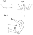
- Fig. 2 shows a cover plate in side view.
- Fig. 3 shows an opening in the end plate.
- 4 shows a perspective view of the end plate
- the connecting device 5 has in the exemplary embodiment a stepped cylindrical shape and is seated with its connection edge 6 on the edge of an adapted circular opening 4 in the end plate 3 of a housing-less plate heat exchanger.
- connection edge 6 and the opening 4 and the line connection end 22 of the connection device 5 could, for example, have a square cross section or any feasible cross section.
- the connection device 5 is a plastic part produced by the well-known injection molding method. With this method, such connection devices 5 are mass-produced very cost-effectively fully automatically.
- the illustrated mechanical attachment of the connecting device 5 at the erect edge of the opening 4 may be a permanent connection, since the replacement of the connecting device 5 is usually not required.
- the edge of the opening 4 is provided with a deformation 7 .
- the deformation 7 is formed as an upright edge 77 , as shown in FIG. 2 shows particularly clearly.
- a seat 8 for the connection edge 6 of the connection device 5 was pronounced, which has a reduced wall thickness compared to the remaining wall thickness of the end plate 3 .
- the edge 77 has crenellated projections 9. (FIG. 3) From FIG. 1 it can be clearly seen that the projections 9 have been bent down onto the connecting edge 6 of the connecting device.
- a seal 10 is located between the terminal edge 6 and the edge 77th
- the end plate 3 has a total of four openings 4.
- the openings 4 are located above each one inlet and outlet channel 20 which passes through the stack of heat exchanger plates 1, 2 .
- a channel 20 has been indicated.
- two of the four openings 4 have been provided with a deformation 7 , which are designed for the mechanical fastening of a connection device 5 made of plastic, as described above.
- the mentioned two openings 4 are in this embodiment those for the supply and for the discharge of a cooling liquid W.
- the others in Fig. 4th shown two openings 4 are intended for the supply and for the discharge of the transmission oil oil.
- the outer shape of the end plate 3 is approximately identical to the shape of a horizontal section through the plate heat exchanger, not shown.
- the body of the plate heat exchanger in the embodiment has two opposite long sides and two opposite shorter sides, wherein one of the shorter sides is semicircular.
- the end plate 3 is slightly smaller because it is flat in the uppermost trough-shaped heat exchanger plate 2 and the protruding edge 21 of the heat exchanger plate 2 projects slightly beyond the circumference of the end plate 3 . (See Fig. 1)
- the position of the openings 4 and the channels 20 depends on the application.
Landscapes
- Engineering & Computer Science (AREA)
- Physics & Mathematics (AREA)
- Thermal Sciences (AREA)
- Mechanical Engineering (AREA)
- General Engineering & Computer Science (AREA)
- Heat-Exchange Devices With Radiators And Conduit Assemblies (AREA)
Abstract
Description
- Die Erfindung betrifft einen Plattenwärmetauscher, bestehend aus Wärmetauscherplatten und wenigstens einer Abschlussplatte mit einer Öffnung, an der eine Anschlussvorrichtung, mit ihrem Anschlussrand die Öffnung umgreifend, befestigt ist, um ein wärmetauschendes Medium dem Plattenwärmetauscher zuzuleiten bzw. vom Plattenwärmetauscher abzuleiten, wobei die Abschlussplatte um ihre Öffnung herum eine Verformung aufweist,
Ein solcher Plattenwärmetauscher wurde in der von derselben Anmelderin stammenden europäischen Patentanmeldung EP 1 176 380 A2 gezeigt und beschrieben. Die Anschlussvorrichtung ist dort aus Metall, insbesondere aus Aluminiumblech, hergestellt worden, um dieselbe bei der Herstellung des Plattenwärmetauschers in einem einzigen Lötvorgang gleichzeitig mit anbringen zu können. In dem in der dortigen Fig. 4 gezeigten Ausführungsbeispiel, wurde die Abschlussplatte mittels Tiefziehen umgeformt und nimmt in dem umgeformten Bereich einen Anschlussflansch auf, der dort angelötet wird.
Die Ausbildung der Anschlussvorrichtung aus Metall ist bei solchen Plattenwärmetauschern scheinbar ausschließlich anzutreffen, denn auch beispielsweise bei dem aus der DE 29 23 944 bekannten Plattenwärmetauscher wurde eine Anschlussvorrichtung aus Metall vorgesehen, die dort an einer Endplatte 2a angeschweißt wurde. Jede zweite Wärmetauscherplatte hat an ihrer den Zu - oder Ablaufkanal bildenden Öffnung jeweils einen Durchzug, dort als rohrförmiger Ansatz 14 bezeichnet, wodurch die Wärmetauscherplatten günstig zentriert und, unter Bildung getrennter horizontaler Kanäle, verschweißt werden können. Die Anschlussvorrichtung sitzt mit ihrer zentralen Öffnung auf den Durchzügen der ersten und der dritten Wärmetauscherplatte auf. Dieser Konstruktion können kaum Nachteile nachgesagt werden. Jedoch wenn Wärmetauscherplatten äußerst geringer Blechdicke vorgesehen werden sollen, dann könnte die Positionssicherung der Anschlussvorrichtung nicht stabil genug sein. Die Anschlussvorrichtung stellt einen großen Anteil an den Herstellungskosten des bekannten Plattenwärmetauschers dar. - Genau wie in der zuerst genannten Schrift soll auch mit der vorliegenden Anmeldung ein kostengünstigerer Plattenwärmetauscher vorgeschlagen werden.
- Diese Aufgabe wird bei dem vorne beschriebenen Plattenwärmetauscher durch die kennzeichnenden Merkmale des Anspruchs 1 erfindungsgemäß gelöst.
- Es ist vorgesehen, dass die Anschlussvorrichtung ein Spritzgussteil, vorzugsweise aus Kunststoff, ist, und dass die Verformung als Befestigungsmittel zur mechanischen Befestigung der Anschlussvorrichtung an der Abschlussplatte ausgebildet ist. Es hat sich herausgestellt, dass dadurch insgesamt eine Kostenersparnis in beachtlicher Höhe erreicht werden kann, die sich hauptsächlich durch die kostengünstige Herstellung der Anschlussvorrichtung als Spritzgussteil einstellt. Die Funktionseigenschaften werden zu 100% gewährleistet, insbesondere dann, wenn der Plattenwärmetauscher als Ölkühler zum Einsatz kommt. Der bei diesem Einsatz vorkommende Temperaturbereich wird von den bekannten Kunststoffen in ausreichender Weise abgedeckt.
Die Herstellung vergleichbarer Anschlussvorrichtungen als Spritzgussteil aus Kunststoff gehört auch nach Auffassung der Anmelderin schon lange zum Stand der Technik. Die Umsetzung dessen im Zusammenhang mit Plattenwärmetauschern scheint jedoch einen erfinderischen Gedanken zu enthalten. Jedenfalls ist dieser der Anmelderin bis zum jetzigen Zeitpunkt nicht bekannt gewesen. - Es ist vorgesehen, dass die Verformung um die Öffnung herum als aufgerichteter Rand ausgebildet ist, der zur mechanischen Befestigung zum Anschlussrand der Anschlussvorrichtung hin umbiegbar ist.
Darüber hinaus wurde daran gedacht, die Verformung mit einem Sitz für den Anschlussrand auszubilden. Aus diesem Grund ist es vorteilhaft, wenn die Verformung eine Wanddickenreduktion der Abschlussplatte aufweist, denn dadurch wird der Sitz eingeebnet und bietet bessere Dichtigkeitseigenschaften bzw. eine verbesserte Passung zwischen Anschlussrand und verformtem Öffnungsrand. Der Rand lässt sich durch die Wanddickenreduktion auch etwas verlängern und kann somit Anschlussvorrichtungen mit größer dimensionierten Anschlussrändern besser umfassen.
Zwischen dem Anschlussrand und der Verformung soll zusätzlich eine Dichtung angeordnet sein, die beim Umbiegen des Randes anpressbar ist.
Vorteilhaft ist ebenfalls, dass der Rand mit zinnenartigen Vorsprüngen ausgebildet ist, denn dadurch wird das Umbiegen des Randes nach außen erleichtert, wobei die Befestigungsfestigkeit trotzdem erhalten bleibt. Die Abschlussplatten weisen bei solchen Plattenwärmetauschern gewöhnlich eine Blechdicke von beispielsweise 1, 0 bis 2,0 mm auf. Sie sind deshalb geeignet, die dichte, dauerhafte und gegen mechanische Einflüsse ausreichend feste mechanische Verbindung bzw. Befestigung der Anschlussvorrichtung zu gewährleisten.
Die Anschlussvorrichtung weist gegenüber dem Anschlussrand vorzugsweise eine Querschnittserweiterung auf, die ein Leitungsanschlussende aufnimmt. In der Erweiterung kann auch ein Kupplungsstück sitzen, das am Leitungsanschlussende befestigt ist. Das Kupplungsstück befindet sich dann zwischen dem Leitungsanschlussende und der Querschnittserweiterung der Anschlussvorrichtung. Anstelle der Erweiterung kann es sich jedoch auch um einen im Querschnitt reduzierten Absatz handeln.
Die bevorzugte Bauart des Plattenwärmetauschers selbst ist die bekannte und oftmals sogenannte "gehäuselose" Plattenbauweise. Das bevorzugte Einsatzgebiet sind Ölkühler für Kraftfahrzeuge. Solche Ölkühler besitzen wannenförmige Wärmetauscherplatten mit je vier Öffnungen, die ineinander gestapelt sind. Dabei bilden jeweils zwei Öffnungen den Einlasskanal bzw. den Auslasskanal für das Kühlmittel, beispielsweise Kühlflüssigkeit. Die anderen zwei Öffnungen bilden entsprechend den Einlasskanal bzw. den Auslasskanal für das Öl. Zwischen den beabstandeten Wärmetauscherplatten befinden sich, bevorzugt in abwechselnder Reihenfolge und senkrecht zu den Ein - und Auslasskanälen angeordnete Strömungskanäle für das ÖI und für das Kühlmittel, die mit dem ihnen zugeordneten Einlasskanal und mit dem Auslasskanal hydraulisch verbunden sind.
Wegen der beschriebenen Bauweise wird beispielsweise auf die DE 103 04 733A1 verwiesen.
Die Erfindung wird nachfolgend in einem Ausführungsbeispiel anhand der beigefügten Zeichnungen beschrieben, welches keinesfalls einschränkend aufgefasst werden soll.
Die Fig. 1 zeigt einen Schnitt durch die Anschlussvorrichtung und durch lediglich einen Teil des Plattenwärmetauschers. Die Fig. 2 zeigt eine Abschlussplatte in Seitenansicht. Die Fig. 3 zeigt eine Öffnung in der Abschlussplatte. Die Fig. 4 zeigt einen perspektivischen Blick auf die Abschlussplatte
Die Anschlussvorrichtung 5 besitzt im Ausführungsbeispiel eine abgesetzte zylindrische Gestalt und sitzt mit ihrem Anschlussrand 6 auf dem Rand einer angepassten kreisförmigen Öffnung 4 in der Abschlussplatte 3 eines gehäuselosen Plattenwärmetauschers. Vom Plattenwärmetauscher selbst ist lediglich ein Teil der Abschlussplatte 3 und ein Teil zweier wannenförmiger Wärmetauscherplatten 1, 2 in der Fig. 1 erkennbar. Bezüglich der weiteren Gestaltung des Plattenwärmetauschers wird nochmals auf DE 103 04 733 A1 hingewiesen. Es handelt sich um die obere Abschlussplatte 3, die im gezeigten Ausführungsbeispiel flach in der oberen wannenförmigen Wärmetauscherplatte 2 liegt. Eine vergleichbare Abschlussplatte 3 könnte auch am nicht gezeigten unteren Ende des Plattenwärmetauschers vorgesehen sein. Die Öffnung 4 in der Abschlussplatte 3 und die Öffnung in den Wärmetauscherplatten 1, 2 bilden einen der vertikalen Ein - oder Auslasskanäle 20 des Plattenwärmetauschers. Vier solche Ein - oder Auslasskanäle 20 sind gewöhnlich bei Plattenwärmetauschern vorgesehen. Sowohl der Anschlussrand 6 und die Öffnung 4 als auch das Leitungsanschlussende 22 der Anschlussvorrichtung 5 könnten beispielsweise einen quadratischen Querschnitt oder einen beliebigen realisierbaren Querschnitt aufweisen. Die Anschlussvorrichtung 5 ist ein mit dem gut bekannten Spritzgussverfahren hergestelltes Teil aus Kunststoff. Mit diesem Verfahren sind solche Anschlussvorrichtungen 5 als Massenprodukt sehr kostengünstig vollautomatisch herstellbar. - Die gezeigte mechanische Befestigung der Anschlussvorrichtung 5 am aufgerichteten Rand der Öffnung 4 kann eine unlösbare Verbindung sein, da das Auswechseln der Anschlussvorrichtung 5 in der Regel nicht erforderlich ist.
- Der Rand der Öffnung 4 ist mit einer Verformung 7 versehen. Die Verformung 7 ist als aufgerichteter Rand 77 ausgebildet, wie die Fig. 2 besonders deutlich zeigt. Es wurde ein Sitz 8 für den Anschlussrand 6 der Anschlussvorrichtung 5 ausgeprägt, der gegenüber der restlichen Wanddicke der Abschlussplatte 3 eine reduzierte Wanddicke aufweist. Der Rand 77 besitzt zinnenartige Vorsprünge 9. (Fig. 3) Aus der Fig. 1 ist deutlich zu sehen, dass die Vorsprünge 9 auf den Anschlussrand 6 der Anschlussvorrichtung herunter gebogen wurden. Eine Dichtung 10 befindet sich zwischen dem Anschlussrand 6 und dem Rand 77.
- Wie die Fig. 4 zeigt, besitzt die Abschlussplatte 3 insgesamt vier Öffnungen 4. Die Öffnungen 4 befinden sich oberhalb je eines Ein - bzw. Auslasskanals 20 der durch den Stapel aus Wärmetauscherplatten 1, 2 hindurchgeht. In der Fig. 1 wurde ein solcher Kanal 20 angedeutet. In der Fig. 4 wurden zwei der vier Öffnungen 4 mit einer Verformung 7 versehen, die zur mechanischen Befestigung einer Anschlussvorrichtung 5 aus Kunststoff - wie oben beschrieben - ausgebildet sind. Die erwähnten zwei Öffnungen 4 sind in diesem Ausführungsbeispiel diejenigen für die Zuführung und für die Abführung einer Kühlflüssigkeit W. Die anderen in Fig. 4 gezeigten zwei Öffnungen 4 sind für die Zuführung und für die Abführung des Getriebeöles Öl gedacht. Die äußere Form der Abschlussplatte 3 ist etwa identisch mit der Form eines Horizontalschnittes durch den nicht gezeigten Plattenwärmetauscher. Es ist demnach erkennbar, dass der Körper des Plattenwärmetauschers im Ausführungsbeispiel zwei gegenüberliegende lange Seiten und zwei gegenüberliegende kürzere Seiten aufweist, wobei eine der kürzeren Seiten halbkreisartig ausgebildet ist. Die Abschlussplatte 3 ist geringfügig kleiner, weil dieselbe flach in der obersten wannenförmigen Wärmetauscherplatte 2 liegt und der abstehende Rand 21 der Wärmetauscherplatte 2 etwas über den Umfang der Abschlussplatte 3 ragt. (siehe Fig. 1) Die Position der Öffnungen 4 und der Kanäle 20 hängt vom Anwendungsfall ab.
Claims (9)
- Plattenwärmetauscher, bestehend aus Wärmetauscherplatten (1, 2) und wenigstens einer Abschlussplatte (3) mit einer Öffnung (4), an der eine Anschlussvorrichtung (5), mit ihrem Anschlussrand (6) die Öffnung (4) umgreifend, befestigt ist, um ein wärmetauschendes Medium dem Plattenwärmetauscher zuzuleiten bzw. vom Plattenwärmetauscher abzuleiten, wobei die Abschlussplatte (3) um ihre Öffnung (4) herum eine Verformung (7) aufweist,
dadurch gekennzeichnet, dass die Anschlussvorrichtung (5) als Spritzgussteil hergestellt ist, und dass die Verformung (7) als Befestigungsmittel zur mechanischen Befestigung der Anschlussvorrichtung (5) an der Abschlussplatte (3) ausgebildet ist. - Plattenwärmetauscher nach Anspruch 1, dadurch gekennzeichnet, dass die Verformung (7) um die Öffnung (4) herum als aufgerichteter Rand (77) ausgebildet ist, der zur mechanischen Befestigung zum Anschlussrand (6) der Anschlussvorrichtung (5) hin umbiegbar ist.
- Plattenwärmetauscher nach einem der vorstehenden Ansprüche, dadurch gekennzeichnet, dass die Verformung (7) mit einem Sitz (8) für den Anschlussrand (6) ausgebildet ist.
- Plattenwärmetauscher nach Anspruch 3, dadurch gekennzeichnet, dass die Verformung (7) eine Wanddickenreduktion der Abschlussplatte (3) im Bereich des Sitzes (8) aufweist.
- Plattenwärmetauscher nach einem der vorstehenden Ansprüche, dadurch gekennzeichnet, dass zwischen dem Anschlussrand (6) und der Verformung (7) eine Dichtung (10) angeordnet ist, die beim Umbiegen des Randes (77) anpressbar ist.
- Plattenwärmetauscher nach den Ansprüchen 3 und 5, dadurch gekennzeichnet, dass der Rand (77) mit zinnenartigen Vorsprüngen (9) ausgebildet ist.
- Plattenwärmetauscher nach einem der vorstehenden Ansprüche, dadurch gekennzeichnet, dass die Anschlussvorrichtung (5) gegenüber dem Anschlussrand (6) vorzugsweise eine Querschnittserweiterung (16) zur Aufnahme beispielsweise eines Leitungsanschlussendes (22) aufweist, wobei eine Abdichtung (11) in der Erweiterung (16) angeordnet ist.
- Plattenwärmetauscher nach einem der vorstehenden Ansprüche, dadurch gekennzeichnet, dass der Plattenwärmetauscher in gehäuseloser Bauweise ausgeführt ist und als Ölkühler verwendet wird.
- Plattenwärmetauscher nach einem der vorstehenden Ansprüche, dadurch gekennzeichnet, dass die Anschlussvorrichtung (5) aus Kunststoff besteht.
Applications Claiming Priority (1)
| Application Number | Priority Date | Filing Date | Title |
|---|---|---|---|
| DE102004049988A DE102004049988A1 (de) | 2004-10-14 | 2004-10-14 | Plattenwärmetauscher |
Publications (2)
| Publication Number | Publication Date |
|---|---|
| EP1647796A1 true EP1647796A1 (de) | 2006-04-19 |
| EP1647796B1 EP1647796B1 (de) | 2007-12-26 |
Family
ID=35759397
Family Applications (1)
| Application Number | Title | Priority Date | Filing Date |
|---|---|---|---|
| EP05021987A Expired - Lifetime EP1647796B1 (de) | 2004-10-14 | 2005-10-08 | Plattenwärmetauscher |
Country Status (3)
| Country | Link |
|---|---|
| US (1) | US20060108095A1 (de) |
| EP (1) | EP1647796B1 (de) |
| DE (2) | DE102004049988A1 (de) |
Families Citing this family (2)
| Publication number | Priority date | Publication date | Assignee | Title |
|---|---|---|---|---|
| DE102006005084A1 (de) * | 2006-02-04 | 2007-08-09 | Modine Manufacturing Co., Racine | Wärmetauscher, insbesondere Ölkühler |
| US20160076676A1 (en) * | 2014-09-15 | 2016-03-17 | Denso International America, Inc. | Connector device, connector having the same and tank for heat exchanger having the connector |
Citations (9)
| Publication number | Priority date | Publication date | Assignee | Title |
|---|---|---|---|---|
| DE2923944A1 (de) | 1978-06-14 | 1980-03-13 | Piemontese Radiatori | Plattenwaermetauscher |
| DE3615904A1 (de) * | 1985-07-24 | 1987-02-05 | Rasmussen Gmbh | Steckkupplung |
| DE3702246C1 (de) * | 1987-01-27 | 1988-03-10 | Rasmussen Gmbh | Steckkupplung zum Verbinden eines Schlauches mit einem Rohr |
| EP0682215A1 (de) * | 1994-05-13 | 1995-11-15 | GIANNONI S.r.l. | Eine dichte Verbindung zum Verbinden einer Platte mit einem Rohr |
| DE19805439A1 (de) * | 1998-02-11 | 1999-08-12 | Behr Gmbh & Co | Verfahren zur Herstellung eines Stapelscheibenwärmeübertragers und dadurch hergestellter Wärmeübertrager |
| EP1176380A2 (de) | 2000-07-27 | 2002-01-30 | Modine Manufacturing Company | Anschluss für Plattenwärmetauscher |
| DE10160380A1 (de) * | 2001-12-10 | 2003-06-18 | Bosch Gmbh Robert | Vorrichtung zur Wärmeübertragung |
| EP1400772A2 (de) * | 2002-09-19 | 2004-03-24 | Modine Manufacturing Company | Plattenwärmeübertrager |
| DE10304733A1 (de) | 2003-02-06 | 2004-08-19 | Modine Manufacturing Co., Racine | Plattenwärmetauscher |
Family Cites Families (16)
| Publication number | Priority date | Publication date | Assignee | Title |
|---|---|---|---|---|
| US167339A (en) * | 1875-08-31 | Improvement in devices for securing boiler-tubes | ||
| US1382049A (en) * | 1920-06-22 | 1921-06-21 | Lincoln Mfg Company | Method of securing a nipple to a hollow shell and article produced thereby |
| US3374014A (en) * | 1965-07-27 | 1968-03-19 | Standard Pressed Steel Co | Swaged seals |
| JP2541409B2 (ja) * | 1991-11-15 | 1996-10-09 | 日本電装株式会社 | 熱交換器 |
| US5253773A (en) * | 1992-08-26 | 1993-10-19 | General Signal Corporation | Filler tube for liquid containers |
| JP3021205B2 (ja) * | 1992-08-31 | 2000-03-15 | 三菱重工業株式会社 | 熱交換器用ヘッダ |
| CA2153528C (en) * | 1995-07-10 | 2006-12-05 | Bruce Laurance Evans | Plate heat exchanger with reinforced input/output manifolds |
| DE69713724T2 (de) * | 1996-12-03 | 2002-11-14 | Calsonic Kansei Corp., Tokio/Tokyo | Befestigungsvorrichtung für Ölkühler und Verfahren zur Befestigung eines Ölkühlers |
| US6186223B1 (en) * | 1998-08-27 | 2001-02-13 | Zeks Air Drier Corporation | Corrugated folded plate heat exchanger |
| DE19951429B4 (de) * | 1999-10-26 | 2005-02-24 | Behr Gmbh & Co. Kg | Rohranschluß für einen Ölkühler |
| US6517117B1 (en) * | 2000-11-13 | 2003-02-11 | Han-Chin Lai | Through wall connector for a reservoir |
| DE20101378U1 (de) * | 2001-01-26 | 2002-05-29 | Viessmann Werke GmbH & Co., 35108 Allendorf | Wärmetauscher |
| US6341649B1 (en) * | 2001-02-12 | 2002-01-29 | Delphi Technologies, Inc. | Aluminum plate oil cooler |
| ATE441073T1 (de) * | 2001-11-08 | 2009-09-15 | Behr Gmbh & Co Kg | Wärmetauscher |
| CA2384712A1 (en) * | 2002-05-03 | 2003-11-03 | Michel St. Pierre | Heat exchanger with nest flange-formed passageway |
| KR100513008B1 (ko) * | 2002-08-27 | 2005-09-05 | 엘지전자 주식회사 | 냉장고 열교환기의 냉매 누설 방지 구조 |
-
2004
- 2004-10-14 DE DE102004049988A patent/DE102004049988A1/de not_active Withdrawn
-
2005
- 2005-10-08 EP EP05021987A patent/EP1647796B1/de not_active Expired - Lifetime
- 2005-10-08 DE DE502005002337T patent/DE502005002337D1/de not_active Expired - Lifetime
- 2005-10-11 US US11/248,075 patent/US20060108095A1/en not_active Abandoned
Patent Citations (10)
| Publication number | Priority date | Publication date | Assignee | Title |
|---|---|---|---|---|
| DE2923944A1 (de) | 1978-06-14 | 1980-03-13 | Piemontese Radiatori | Plattenwaermetauscher |
| DE3615904A1 (de) * | 1985-07-24 | 1987-02-05 | Rasmussen Gmbh | Steckkupplung |
| DE3702246C1 (de) * | 1987-01-27 | 1988-03-10 | Rasmussen Gmbh | Steckkupplung zum Verbinden eines Schlauches mit einem Rohr |
| EP0682215A1 (de) * | 1994-05-13 | 1995-11-15 | GIANNONI S.r.l. | Eine dichte Verbindung zum Verbinden einer Platte mit einem Rohr |
| DE19805439A1 (de) * | 1998-02-11 | 1999-08-12 | Behr Gmbh & Co | Verfahren zur Herstellung eines Stapelscheibenwärmeübertragers und dadurch hergestellter Wärmeübertrager |
| EP1176380A2 (de) | 2000-07-27 | 2002-01-30 | Modine Manufacturing Company | Anschluss für Plattenwärmetauscher |
| DE10160380A1 (de) * | 2001-12-10 | 2003-06-18 | Bosch Gmbh Robert | Vorrichtung zur Wärmeübertragung |
| EP1400772A2 (de) * | 2002-09-19 | 2004-03-24 | Modine Manufacturing Company | Plattenwärmeübertrager |
| DE10304733A1 (de) | 2003-02-06 | 2004-08-19 | Modine Manufacturing Co., Racine | Plattenwärmetauscher |
| EP1452816A2 (de) * | 2003-02-06 | 2004-09-01 | Modine Manufacturing Company | Plattenwärmetauscher |
Also Published As
| Publication number | Publication date |
|---|---|
| DE502005002337D1 (de) | 2008-02-07 |
| EP1647796B1 (de) | 2007-12-26 |
| DE102004049988A1 (de) | 2006-04-20 |
| US20060108095A1 (en) | 2006-05-25 |
Similar Documents
| Publication | Publication Date | Title |
|---|---|---|
| DE69614402T2 (de) | Plattenwärmetauscher | |
| EP0828980B1 (de) | Wärmetauscher | |
| DE19603016C2 (de) | Wärmetauscher | |
| DE69805354T2 (de) | Wärmetauscher | |
| EP1654508B2 (de) | Wärmeübertrager sowie verfahren zu dessen herstellung | |
| DE69315281T2 (de) | Plattenwärmetauscher und Verfahren zu dessen Herstellung | |
| EP1306638B1 (de) | Gehäuseloser Plattenwärmetauscher | |
| EP1452816B1 (de) | Plattenwärmetauscher | |
| WO2005071342A1 (de) | Wärmetauscher, insbesondere öl-/kühlmittel-kühler | |
| EP1273864B1 (de) | Wärmetauscher | |
| DE3500571A1 (de) | Kuehler fuer kraftfahrzeuge | |
| DE3203356A1 (de) | Waermeaustauscher | |
| DE19953787B4 (de) | Anordnung zur Verbindung von zwei Wärmeübertragern | |
| DE20121112U1 (de) | Sammelkasten für einen Wärmeaustauscher, insbesondere an Kraftfahrzeugen | |
| DE102005002417A1 (de) | Wärmeübertrager, insbesondere Ladeluftkühler oder Kühlmittelkühler für Kraftfahrzeuge | |
| DE69903895T2 (de) | Wärmetauscher | |
| DE102017219433A1 (de) | Wärmeübertrager für einen Verbrennungsmotor | |
| EP2167895B1 (de) | Wärmetauscher | |
| DE112018001423B4 (de) | Anordnung eines Verbindungsstücks | |
| DE69507074T2 (de) | Lamellenwärmeaustauscher mit einem einzigen Sammelkanal | |
| EP1647796B1 (de) | Plattenwärmetauscher | |
| DE10121173B4 (de) | Rohrverbindungskonstruktion für einen Wärmetauscher | |
| EP1912035B1 (de) | Kraftfahrzeugkühler | |
| EP1384968B1 (de) | Wärmeübertrager und Herstellungsverfahren | |
| EP1189006B1 (de) | Kühleranordnung |
Legal Events
| Date | Code | Title | Description |
|---|---|---|---|
| PUAI | Public reference made under article 153(3) epc to a published international application that has entered the european phase |
Free format text: ORIGINAL CODE: 0009012 |
|
| AK | Designated contracting states |
Kind code of ref document: A1 Designated state(s): AT BE BG CH CY CZ DE DK EE ES FI FR GB GR HU IE IS IT LI LT LU LV MC NL PL PT RO SE SI SK TR |
|
| AX | Request for extension of the european patent |
Extension state: AL BA HR MK YU |
|
| 17P | Request for examination filed |
Effective date: 20061019 |
|
| 17Q | First examination report despatched |
Effective date: 20061121 |
|
| AKX | Designation fees paid |
Designated state(s): DE ES FR GB IT SE |
|
| GRAP | Despatch of communication of intention to grant a patent |
Free format text: ORIGINAL CODE: EPIDOSNIGR1 |
|
| RTI1 | Title (correction) |
Free format text: PLATE HEAT EXCHANGER |
|
| RBV | Designated contracting states (corrected) |
Designated state(s): DE FR GB |
|
| GRAS | Grant fee paid |
Free format text: ORIGINAL CODE: EPIDOSNIGR3 |
|
| GRAA | (expected) grant |
Free format text: ORIGINAL CODE: 0009210 |
|
| AK | Designated contracting states |
Kind code of ref document: B1 Designated state(s): DE FR GB |
|
| REG | Reference to a national code |
Ref country code: GB Ref legal event code: FG4D Free format text: NOT ENGLISH |
|
| REF | Corresponds to: |
Ref document number: 502005002337 Country of ref document: DE Date of ref document: 20080207 Kind code of ref document: P |
|
| GBT | Gb: translation of ep patent filed (gb section 77(6)(a)/1977) |
Effective date: 20080327 |
|
| ET | Fr: translation filed | ||
| PLBE | No opposition filed within time limit |
Free format text: ORIGINAL CODE: 0009261 |
|
| STAA | Information on the status of an ep patent application or granted ep patent |
Free format text: STATUS: NO OPPOSITION FILED WITHIN TIME LIMIT |
|
| 26N | No opposition filed |
Effective date: 20080929 |
|
| REG | Reference to a national code |
Ref country code: FR Ref legal event code: PLFP Year of fee payment: 11 |
|
| PGFP | Annual fee paid to national office [announced via postgrant information from national office to epo] |
Ref country code: GB Payment date: 20151027 Year of fee payment: 11 |
|
| PGFP | Annual fee paid to national office [announced via postgrant information from national office to epo] |
Ref country code: FR Payment date: 20151019 Year of fee payment: 11 |
|
| GBPC | Gb: european patent ceased through non-payment of renewal fee |
Effective date: 20161008 |
|
| REG | Reference to a national code |
Ref country code: FR Ref legal event code: ST Effective date: 20170630 |
|
| PG25 | Lapsed in a contracting state [announced via postgrant information from national office to epo] |
Ref country code: GB Free format text: LAPSE BECAUSE OF NON-PAYMENT OF DUE FEES Effective date: 20161008 Ref country code: FR Free format text: LAPSE BECAUSE OF NON-PAYMENT OF DUE FEES Effective date: 20161102 |
|
| REG | Reference to a national code |
Ref country code: DE Ref legal event code: R119 Ref document number: 502005002337 Country of ref document: DE |
|
| REG | Reference to a national code |
Ref country code: DE Ref legal event code: R073 Ref document number: 502005002337 Country of ref document: DE |
|
| REG | Reference to a national code |
Ref country code: DE Ref legal event code: R082 Ref document number: 502005002337 Country of ref document: DE |
|
| PG25 | Lapsed in a contracting state [announced via postgrant information from national office to epo] |
Ref country code: DE Free format text: LAPSE BECAUSE OF NON-PAYMENT OF DUE FEES Effective date: 20210501 |
|
| REG | Reference to a national code |
Ref country code: DE Ref legal event code: R082 Ref document number: 502005002337 Country of ref document: DE Representative=s name: TER MEER STEINMEISTER & PARTNER PATENTANWAELTE, DE Ref country code: DE Ref legal event code: R082 Ref document number: 502005002337 Country of ref document: DE |
|
| REG | Reference to a national code |
Ref country code: DE Ref legal event code: R074 Ref document number: 502005002337 Country of ref document: DE |
|
| PG25 | Lapsed in a contracting state [announced via postgrant information from national office to epo] |
Ref country code: DE Free format text: LAPSE BECAUSE OF NON-PAYMENT OF DUE FEES Effective date: 20210501 |
|
| PGRI | Patent reinstated in contracting state [announced from national office to epo] |
Ref country code: DE Effective date: 20210807 |
|
| PGFP | Annual fee paid to national office [announced via postgrant information from national office to epo] |
Ref country code: DE Payment date: 20211027 Year of fee payment: 17 |
|
| REG | Reference to a national code |
Ref country code: DE Ref legal event code: R119 Ref document number: 502005002337 Country of ref document: DE |
|
| REG | Reference to a national code |
Ref country code: DE Ref legal event code: R082 Ref document number: 502005002337 Country of ref document: DE Representative=s name: TER MEER STEINMEISTER & PARTNER PATENTANWAELTE, DE |
|
| PG25 | Lapsed in a contracting state [announced via postgrant information from national office to epo] |
Ref country code: DE Free format text: LAPSE BECAUSE OF NON-PAYMENT OF DUE FEES Effective date: 20230503 |