EP1646771B1 - Kraftfahrzeugk hlmittelkreislauf mit pumpe und retarder - Google Patents
Kraftfahrzeugk hlmittelkreislauf mit pumpe und retarder Download PDFInfo
- Publication number
- EP1646771B1 EP1646771B1 EP04740833A EP04740833A EP1646771B1 EP 1646771 B1 EP1646771 B1 EP 1646771B1 EP 04740833 A EP04740833 A EP 04740833A EP 04740833 A EP04740833 A EP 04740833A EP 1646771 B1 EP1646771 B1 EP 1646771B1
- Authority
- EP
- European Patent Office
- Prior art keywords
- retarder
- coolant
- pump
- coolant circuit
- stator
- Prior art date
- Legal status (The legal status is an assumption and is not a legal conclusion. Google has not performed a legal analysis and makes no representation as to the accuracy of the status listed.)
- Expired - Lifetime
Links
- 239000002826 coolant Substances 0.000 title claims description 90
- 238000009827 uniform distribution Methods 0.000 claims description 3
- 238000002485 combustion reaction Methods 0.000 claims 2
- 230000001186 cumulative effect Effects 0.000 claims 1
- 238000001816 cooling Methods 0.000 description 10
- 230000005540 biological transmission Effects 0.000 description 9
- XLYOFNOQVPJJNP-UHFFFAOYSA-N water Substances O XLYOFNOQVPJJNP-UHFFFAOYSA-N 0.000 description 8
- 239000012530 fluid Substances 0.000 description 5
- 239000000498 cooling water Substances 0.000 description 3
- 239000000446 fuel Substances 0.000 description 3
- 239000010720 hydraulic oil Substances 0.000 description 2
- 239000003921 oil Substances 0.000 description 2
- 238000011144 upstream manufacturing Methods 0.000 description 2
- 230000006978 adaptation Effects 0.000 description 1
- 230000001419 dependent effect Effects 0.000 description 1
- 230000000694 effects Effects 0.000 description 1
- 230000002349 favourable effect Effects 0.000 description 1
- 230000010354 integration Effects 0.000 description 1
- 238000005086 pumping Methods 0.000 description 1
Images


Classifications
-
- F—MECHANICAL ENGINEERING; LIGHTING; HEATING; WEAPONS; BLASTING
- F16—ENGINEERING ELEMENTS AND UNITS; GENERAL MEASURES FOR PRODUCING AND MAINTAINING EFFECTIVE FUNCTIONING OF MACHINES OR INSTALLATIONS; THERMAL INSULATION IN GENERAL
- F16D—COUPLINGS FOR TRANSMITTING ROTATION; CLUTCHES; BRAKES
- F16D57/00—Liquid-resistance brakes; Brakes using the internal friction of fluids or fluid-like media, e.g. powders
- F16D57/005—Details of blades, e.g. shape
-
- B—PERFORMING OPERATIONS; TRANSPORTING
- B60—VEHICLES IN GENERAL
- B60T—VEHICLE BRAKE CONTROL SYSTEMS OR PARTS THEREOF; BRAKE CONTROL SYSTEMS OR PARTS THEREOF, IN GENERAL; ARRANGEMENT OF BRAKING ELEMENTS ON VEHICLES IN GENERAL; PORTABLE DEVICES FOR PREVENTING UNWANTED MOVEMENT OF VEHICLES; VEHICLE MODIFICATIONS TO FACILITATE COOLING OF BRAKES
- B60T1/00—Arrangements of braking elements, i.e. of those parts where braking effect occurs specially for vehicles
- B60T1/02—Arrangements of braking elements, i.e. of those parts where braking effect occurs specially for vehicles acting by retarding wheels
- B60T1/08—Arrangements of braking elements, i.e. of those parts where braking effect occurs specially for vehicles acting by retarding wheels using fluid or powdered medium
- B60T1/087—Arrangements of braking elements, i.e. of those parts where braking effect occurs specially for vehicles acting by retarding wheels using fluid or powdered medium in hydrodynamic, i.e. non-positive displacement, retarders
-
- B—PERFORMING OPERATIONS; TRANSPORTING
- B60—VEHICLES IN GENERAL
- B60T—VEHICLE BRAKE CONTROL SYSTEMS OR PARTS THEREOF; BRAKE CONTROL SYSTEMS OR PARTS THEREOF, IN GENERAL; ARRANGEMENT OF BRAKING ELEMENTS ON VEHICLES IN GENERAL; PORTABLE DEVICES FOR PREVENTING UNWANTED MOVEMENT OF VEHICLES; VEHICLE MODIFICATIONS TO FACILITATE COOLING OF BRAKES
- B60T10/00—Control or regulation for continuous braking making use of fluid or powdered medium, e.g. for use when descending a long slope
- B60T10/02—Control or regulation for continuous braking making use of fluid or powdered medium, e.g. for use when descending a long slope with hydrodynamic brake
-
- F—MECHANICAL ENGINEERING; LIGHTING; HEATING; WEAPONS; BLASTING
- F01—MACHINES OR ENGINES IN GENERAL; ENGINE PLANTS IN GENERAL; STEAM ENGINES
- F01P—COOLING OF MACHINES OR ENGINES IN GENERAL; COOLING OF INTERNAL-COMBUSTION ENGINES
- F01P3/00—Liquid cooling
- F01P3/20—Cooling circuits not specific to a single part of engine or machine
-
- F—MECHANICAL ENGINEERING; LIGHTING; HEATING; WEAPONS; BLASTING
- F16—ENGINEERING ELEMENTS AND UNITS; GENERAL MEASURES FOR PRODUCING AND MAINTAINING EFFECTIVE FUNCTIONING OF MACHINES OR INSTALLATIONS; THERMAL INSULATION IN GENERAL
- F16D—COUPLINGS FOR TRANSMITTING ROTATION; CLUTCHES; BRAKES
- F16D57/00—Liquid-resistance brakes; Brakes using the internal friction of fluids or fluid-like media, e.g. powders
- F16D57/04—Liquid-resistance brakes; Brakes using the internal friction of fluids or fluid-like media, e.g. powders with blades causing a directed flow, e.g. Föttinger type
-
- F—MECHANICAL ENGINEERING; LIGHTING; HEATING; WEAPONS; BLASTING
- F01—MACHINES OR ENGINES IN GENERAL; ENGINE PLANTS IN GENERAL; STEAM ENGINES
- F01P—COOLING OF MACHINES OR ENGINES IN GENERAL; COOLING OF INTERNAL-COMBUSTION ENGINES
- F01P7/00—Controlling of coolant flow
- F01P7/14—Controlling of coolant flow the coolant being liquid
- F01P2007/146—Controlling of coolant flow the coolant being liquid using valves
Definitions
- the invention relates to a coolant circuit of a motor vehicle, which comprises both a coolant pump and a retarder, wherein the working medium of the retarder is the coolant.
- a hydraulic oil was used as the working medium of a retarder in the drive train of a motor vehicle. Due to the heat generated during braking operation, the hydraulic oil had to be cooled.
- an oil-water heat exchanger was provided as an interface between the cooling circuit and Retarderarbeitsmediumniklauf usually through which the necessary amount of heat was removed from the retarder circuit in the cooling circuit of the vehicle.
- retarders have become known which are arranged directly in the conventional coolant circuit of the vehicle and whose working fluid is the cooling medium of the cooling circuit. By providing such retarders in the cooling circuit, the total flow resistance or the flow resistance of the coolant in the cooling circuit can be increased.
- the drive of the more powerful coolant pump requires more energy, resulting in increased fuel consumption of the motor vehicle. This is particularly significant in that this increased power consumption of the coolant pump is also present when the retarder is not turned on, for example, when it is empty. However, the retarder is usually only used for a relatively small period of time compared to the normal driving operation (without braking the vehicle with the retarder). Finally, a more powerful coolant pump means additional vehicle weight, which also leads to increased fuel consumption.
- US 2 287 130 describes a hydrodynamic brake with a upstream in the flow direction 3-way valve for opening and closing a flow path to the hydrodynamic brake.
- EP 0 794 326 A1 describes a retarder in a combined cooling and brake circuit.
- US3367461 discloses a hydrodynamic brake.
- the invention is based on the object to represent a coolant circuit with a coolant pump and a retarder, which is improved over the prior art.
- a coolant pump which does not require any greater power consumption or power output than coolant pumps in cooling circuits without a retarder.
- FIG. 1 represents a coolant circuit according to the prior art
- FIGS. 2 to 11 show advantageous embodiments or details of advantageous embodiments of inventive coolant circuits.
- FIG. 1 One recognizes a coolant circuit 10 and a retarder working medium circuit 11. According to the prior art, both circuits are carried out separately.
- the coolant in the coolant circuit 10 is circulated by means of the coolant pump 1 and the working fluid in the retarder 11 by means of the retarder 2.
- Both circuits are interconnected by means of an oil-water heat exchanger 12 such that the heat generated in the retarder 2 is transferred to the coolant circuit 10 ,
- Out the coolant circuit 10 the heat is discharged conventionally by means of a cooler 12 together with the impeller 13. If, due to the coolant temperature, there is no need to remove the heat from the coolant circuit 10, the coolant is bypassed by means of the bypass 14 on the radiator.
- a thermostat 15 is provided for a corresponding regulation.
- the necessary for energy transport cooling medium flow, in particular cooling water flow, via the motor 5, the water-bearing part of the oil-water heat exchanger 12, via the thermostat 15 and the water-air cooler 12 to the suction side of the pump 1 moves.
- the circulating flow resistances are to be overcome by the pump 1, that is, the pump must absorb or release so much power that the pressure of the working medium so far above the suction side due to the pressure level generated by the pump at the pump outlet 1.1 , Pressure level is that adjusts a corresponding circulation flow through the entire coolant circuit.
- Such an additional resistance for example, the oil-water heat exchanger 12 is. Considering that the retarder is necessary only for about 10 percent of vehicle use for braking, the remaining 90 percent of the vehicle use a pump operation with unnecessarily high power consumption.
- FIG. 2 shows a coolant circuit designed according to the invention.
- the corresponding elements are given the same reference numerals as in FIG. 1 characterized.
- the retarder 2 is arranged directly in the coolant circuit and bypassed by the bypass section 4.
- a changeover valve 3 is arranged to control the flow, either through the retarder 2 or through the bypass 4.
- coolant pump 1 corresponds in its power range of a coolant pump of a coolant circuit without directly introduced retarder or without introduced oil-water heat exchanger for a separate retarder, as in the FIG. 1 is shown.
- the coolant pump 1 circulates the coolant in the coolant circuit 10, beginning with the pressure level of the coolant outlet 1.1 of the pump 1, via the changeover valve 3, the bypass 4, the engine 5, the thermostat 15, the Radiator 12 (or possibly at least partially over the bypass 14 past this) to the suction side of the pump 1.
- the switching valve 3 is particularly advantageously designed such that it does not represent an additional impediment to the flow circuit.
- a particularly advantageous embodiment of such a switching valve is in the FIG. 5 and will be described below.
- the coolant pump has a performance range over the performance range of the retarder in terms of the possible pumping power in the ratio of 1: 100.
- the pump has a power of about 6 kilowatts and the retarder has a power range of 500 to 600 kilowatts.
- the flow resistance to be overcome by the coolant pump 1 during braking operation is lower than in non-braking operation, an increased circulating volume of cooling medium is established.
- This is particularly advantageous in the retarder braking operation to increase the thermal availability of such a brake system and thus to extend the possible wear-free braking operation comparatively, which leads to the relief of wear brakes provided in the vehicle.
- the retarder is arranged in the flow direction in front of the motor to be cooled 5, once the to be overcome by the coolant pump flow resistance can be kept particularly low, which increases the throughput at the same speed, and on the other hand, the working fluid in the retarder a relatively low temperature on.
- FIG. 3 an alternative embodiment of a coolant circuit 10 is shown. This time, the engine 5 is seen behind the coolant pump 1 and upstream of the switching valve 3 as seen in the flow direction. Nevertheless, according to the invention, the flow resistance between the cooling medium outlet 1.1 of the pump 1 and the core ring of the retarder 2 is selected such that it is smaller than the total flow resistance in the coolant circuit with the retarder 2 switched off, that is to say when the bypass 4 flows through.
- the heated coolant in the retarder is cooled immediately below in the vehicle radiator 12.
- the retarder coolant temperatures can be allowed, which are above the permissible coolant inlet temperatures at the motor 5.
- a particularly short coolant-carrying route between coolant pump 1 and retarder 2 can then be achieved if the retarder is designed as a primary retarder with regard to its mechanical integration into the system.
- Primary retarder means that the retarder is arranged in drive connection between the engine 5 and a transmission, not shown, on the transmission drive side. Characterized in that thus the water pump and retarder are both arranged on the engine side with respect to the transmission, the short fluid guide between the pump 1 and retarder 2 and a correspondingly low flow resistance is executable.
- the arrangement according to the FIG. 3 offers in addition to the advantages mentioned the further advantage that the retarder 2 can be particularly easily performed as a secondary retarder.
- Secondary retarder means that the retarder is arranged in a drive connection on the transmission output side, that is, between the transmission and the vehicle wheels. This is favorable because more space is available on the transmission output side in the frame region of a vehicle than in the area of the engine compartment on the transmission drive side.
- FIG. 4 an embodiment is shown, in which the retarder 2 is secondarily arranged in terms of its mechanical effect, that is arranged on the transmission output side, while in its arrangement in the coolant circuit, however, is arranged in front of the motor 5.
- the flow guide from the outlet 1.1 of the coolant pump 1 to the core ring of the retarder 2 is designed such that the flow resistance of this route is less than the flow resistance in non-braking operation of the entire coolant circuit 10th
- an adaptation of the flow resistance between the pump outlet 1.1 and the core ring of the retarder 2 can be performed by a predetermined number of holes in the filling system of the retarder.
- the number and / or size of the bores or the respective filling cross-sections are advantageously selected according to the respective resistance characteristics of the vehicle cooling system used.
- FIGS. 5a and 5b schematically show an advantageous embodiment of a switching valve 3.
- the reversing valve 3 shown is formed as a rotary valve and has an inlet 3.1, a first outlet 3.2 and a second outlet 3.3. Cooling medium is supplied at least indirectly from the coolant pump 1 via the inlet 3.1. Via an outlet, for example the outlet 3.2, coolant is conducted into the bypass 4 around the retarder and via the other outlet, for example the outlet 3.3, to the retarder 2.
- the switching valve 3 has a cylindrical valve piston 3.4, which is rotatable about its longitudinal axis.
- the cylindrical valve piston has radial bores, namely an outlet bore 3.5 and an inlet bore 3.6.
- the outlet bore 3.5 for example, is cylindrical, while the inlet bore 3.6 is conically tapered or funnel-shaped.
- One, two or more holes can of course also have other shapes in their cross section, for example, those of a slot.
- the conically tapered inlet bore 3.6 has such a dimensioned inlet opening on the circumference of the valve piston 3.4, regardless of the position of the valve piston 3.4 - that is regardless of whether this connects the inlet 3.1 with the outlet 3.2 in flow-conducting or the inlet 3.1 with the outlet 3.3 - the inlet opening of the inlet bore 3.6 completely encloses the flow cross-section of the inlet 3.1.
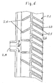
- FIG. 6 shows a with respect to a low-resistance flow in the Retarderkernring Scheme advantageously designed Retardereintritts Switzerland.
- a partial region of the stator 2.2 of the retarder 2 is shown in a developed view.
- the stator 2.2 has a plurality of stator blades 2.7.
- a predetermined number of stator blades 2.7 are provided with a bore 2.3 for supplying working fluid into the working space of the retarder 2.4.
- every second stator blade 2.7 has such a bore 2.3.
- each stator blade would have a corresponding bore.
- Stator blades with bores are also called filling blades.
- the entry into the Retarderkernring Scheme corresponds to the stator outlet, that is, the outlet of the working medium from the holes 2.3 in the filling blades.
- the working medium inlet side 2.5 On the working medium inlet side 2.5, the working medium flows through a central bore 2.8 over the entire circumference of the stator 2.2.
- a number of guide elements 2.6 are provided on the stator inlet side.
- FIG. 7 shows a further measure for aerodynamic design of the retardation entry area.
- two parallel bores 2.3 are introduced for feeding working medium into the working space of the retarder.
- the inlet channel 2.9 in the stator housing 2.10 which is designed as an annular channel (see the indicated dot-dashed center line).
- the stator is provided on its inlet side with guide elements 2.6.
- an outlet channel 2.11 Radially outside the inlet channel 2.9 designed as an annular channel, an outlet channel 2.11, likewise designed as an annular channel, is provided in the stator housing 2.10 in order to remove working medium from the retarder working space via a retarder outlet.
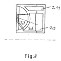
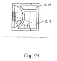
- FIGS. 8 to 11 show further flow resistance reducing measures in the area of the filling blades. So are in accordance with the FIG. 8 the holes 2.3 running in the filling blades of the stator as a conically tapered channel, the inlet opening in the region of the guide element 2.6 almost over the entire Height of the inlet channel 2.9 extends and in the region of the stator outlet side has the shape of a slot or a rectangle.
- FIG. 9 shows a combination of a conically tapered inlet channel with two holes, the inlet channel merges into the two holes.
- FIG. 10 shows an inlet channel, which merges into four stator blade holes.
- FIG. 11 an initially conically tapered channel in the stator blade, which then merges in the flow direction into a channel with a constant cross-section.
Landscapes
- Engineering & Computer Science (AREA)
- General Engineering & Computer Science (AREA)
- Mechanical Engineering (AREA)
- Chemical & Material Sciences (AREA)
- Combustion & Propulsion (AREA)
- Physics & Mathematics (AREA)
- Fluid Mechanics (AREA)
- Transportation (AREA)
- Transmission Of Braking Force In Braking Systems (AREA)
- Braking Arrangements (AREA)
Applications Claiming Priority (2)
| Application Number | Priority Date | Filing Date | Title |
|---|---|---|---|
| DE10332907A DE10332907A1 (de) | 2003-07-19 | 2003-07-19 | Kraftfahrzeugkühlmittelkreislauf mit Pumpe und Retarder |
| PCT/EP2004/007546 WO2005014985A1 (de) | 2003-07-19 | 2004-07-09 | Kraftfahrzeugkühlmittelkreislauf mit pumpe und retarder |
Publications (2)
| Publication Number | Publication Date |
|---|---|
| EP1646771A1 EP1646771A1 (de) | 2006-04-19 |
| EP1646771B1 true EP1646771B1 (de) | 2012-09-12 |
Family
ID=34071790
Family Applications (1)
| Application Number | Title | Priority Date | Filing Date |
|---|---|---|---|
| EP04740833A Expired - Lifetime EP1646771B1 (de) | 2003-07-19 | 2004-07-09 | Kraftfahrzeugk hlmittelkreislauf mit pumpe und retarder |
Country Status (8)
| Country | Link |
|---|---|
| US (1) | US20070131181A1 (https=) |
| EP (1) | EP1646771B1 (https=) |
| JP (1) | JP4767847B2 (https=) |
| KR (1) | KR100740267B1 (https=) |
| CN (1) | CN1826458B (https=) |
| DE (1) | DE10332907A1 (https=) |
| RU (1) | RU2347085C2 (https=) |
| WO (1) | WO2005014985A1 (https=) |
Cited By (2)
| Publication number | Priority date | Publication date | Assignee | Title |
|---|---|---|---|---|
| DE102013001657A1 (de) | 2013-01-31 | 2014-07-31 | Man Truck & Bus Ag | Kühlkreislauf für ein Kraftfahrzeug mit einem hydrodynamischen Retarder |
| DE102017001882A1 (de) | 2017-02-27 | 2018-07-19 | Audi Ag | Verteilereinrichtung zum Verteilen eines fluiden Mediums |
Families Citing this family (19)
| Publication number | Priority date | Publication date | Assignee | Title |
|---|---|---|---|---|
| DE102004061428A1 (de) * | 2004-12-21 | 2006-06-29 | Daimlerchrysler Ag | Kühlkreislauf für ein Kraftfahrzeug und Steuerungsverfahren dafür |
| PL2021666T3 (pl) * | 2006-05-15 | 2018-04-30 | Hollis | Cyfrowy obrotowy zawór regulacyjny |
| DE102007006420A1 (de) * | 2007-02-05 | 2008-08-07 | Voith Patent Gmbh | Kraftfahrzeugantriebsstrang eines Kraftfahrzeugs mit einem Druckluftsystem |
| DE102009005504A1 (de) * | 2009-01-19 | 2010-07-22 | Voith Patent Gmbh | Fahrzeugkühlkreislauf mit einem Retarder oder einer hydrodynamischen Kupplung |
| DE102010051715A1 (de) * | 2010-11-19 | 2012-05-24 | Voith Patent Gmbh | Antriebsstrang mit einem hydrodynamischen Retarder |
| DE102011116933A1 (de) | 2011-10-26 | 2013-05-02 | Man Truck & Bus Ag | Kühlkreislauf für eine flüssigkeitsgekühlteBrennkraftmaschine |
| CN103863271B (zh) * | 2012-12-12 | 2016-11-23 | 北汽福田汽车股份有限公司 | 车辆的冷却系统 |
| CN103486164B (zh) * | 2013-10-15 | 2015-07-22 | 江苏理工学院 | 发动机机油介质式液力缓速装置 |
| CN103481871B (zh) * | 2013-10-15 | 2015-07-22 | 江苏理工学院 | 车用冷却液介质式液力缓速装置 |
| SE538626C2 (sv) * | 2013-10-24 | 2016-10-04 | Scania Cv Ab | Kylsystem i ett fordon |
| DE102014201167A1 (de) | 2014-01-23 | 2015-07-23 | Bayerische Motoren Werke Aktiengesellschaft | Wärmemanagementsystem für eine Verbrennungskraftmaschine |
| WO2015168313A1 (en) * | 2014-04-30 | 2015-11-05 | Cummins Inc. | System and method for optimizing the integration of engines and vehicle driveline retarders |
| KR101642315B1 (ko) * | 2015-04-08 | 2016-07-26 | 한국파워트레인 주식회사 | 유체 리타더의 충진 제어 장치 |
| CN105756763B (zh) * | 2016-03-14 | 2018-10-16 | 潍柴动力股份有限公司 | 一种车辆冷却系统及其控制方法、设有该系统的车辆 |
| DE102016011481A1 (de) | 2016-09-22 | 2018-03-22 | Daimler Ag | Fahrzeugsitz für ein Kraftfahrzeug und Kraftfahrzeug |
| CN110566604B (zh) * | 2019-09-23 | 2024-05-14 | 陕西法士特齿轮有限责任公司 | 一种缓速器主循环系统 |
| DE102019133947A1 (de) * | 2019-12-11 | 2020-12-31 | Voith Patent Gmbh | Kühlsystem |
| CN113323973B (zh) * | 2021-06-29 | 2022-01-28 | 吉林大学 | 一种带减小空载损失装置转子的液力缓速器 |
| CN114135600B (zh) * | 2021-12-31 | 2025-07-08 | 富奥汽车零部件股份有限公司 | 一种缓速器的换热器流量控制油路系统及缓速器 |
Family Cites Families (15)
| Publication number | Priority date | Publication date | Assignee | Title |
|---|---|---|---|---|
| US228713A (en) * | 1880-06-08 | Air-engine | ||
| US2287130A (en) * | 1941-02-26 | 1942-06-23 | Parkersburg Rig & Reed Company | Hydrodynamic brake mechanism |
| DE1530672A1 (de) * | 1963-09-03 | 1969-10-30 | Eaton Yale & Towne | Hydrodynamische Bremseinrichtung fuer Kraftfahrzeuge |
| US3185261A (en) * | 1963-10-25 | 1965-05-25 | Caterpillar Tractor Co | Wheel driven hydrodynamic retarder system |
| US3490567A (en) * | 1968-06-12 | 1970-01-20 | Caterpillar Tractor Co | Engine with hydrodynamic retarder |
| US3721265A (en) * | 1971-04-29 | 1973-03-20 | Fmc Corp | Three-way valve |
| FR2230236A5 (https=) * | 1973-05-14 | 1974-12-13 | Labavia | |
| DE3831596A1 (de) * | 1988-09-14 | 1990-03-22 | Mannesmann Ag | Hydraulische bremse, insbesondere fuer leistungspruefstaende |
| RU2033537C1 (ru) * | 1991-04-02 | 1995-04-20 | Шота Николаевич Хуцишвили | Система охлаждения |
| DE4416039C1 (de) * | 1994-05-06 | 1995-08-31 | Freudenberg Carl Fa | Regelventil |
| US6561324B2 (en) * | 1996-03-08 | 2003-05-13 | Voith Turbo Gmbh & Co. Kg | Drive unit including a motor and a retarder |
| EP0794326A1 (de) * | 1996-03-08 | 1997-09-10 | Voith Turbo GmbH & Co. KG | Antriebseinheit mit einem Motor und einem Retarder |
| DE19641557A1 (de) * | 1996-10-09 | 1997-06-26 | Voith Turbo Kg | Antriebseinheit mit einem Motor, einem Getriebe und einem Kühlmittelkreislauf |
| DE19848544C1 (de) * | 1998-10-22 | 2000-06-21 | Voith Turbo Kg | Verfahren und Vorrichtung zur Erhöhung der Bremsmomentenausnutzung eines hydrodynamischen Retarders in einem Kraftfahrzeug |
| US6539899B1 (en) * | 2002-02-11 | 2003-04-01 | Visteon Global Technologies, Inc. | Rotary valve for single-point coolant diversion in engine cooling system |
-
2003
- 2003-07-19 DE DE10332907A patent/DE10332907A1/de not_active Withdrawn
-
2004
- 2004-07-09 KR KR1020067000202A patent/KR100740267B1/ko not_active Expired - Fee Related
- 2004-07-09 US US10/565,015 patent/US20070131181A1/en not_active Abandoned
- 2004-07-09 JP JP2006519838A patent/JP4767847B2/ja not_active Expired - Fee Related
- 2004-07-09 WO PCT/EP2004/007546 patent/WO2005014985A1/de not_active Ceased
- 2004-07-09 RU RU2006105016/06A patent/RU2347085C2/ru not_active IP Right Cessation
- 2004-07-09 EP EP04740833A patent/EP1646771B1/de not_active Expired - Lifetime
- 2004-07-09 CN CN2004800207251A patent/CN1826458B/zh not_active Expired - Fee Related
Cited By (4)
| Publication number | Priority date | Publication date | Assignee | Title |
|---|---|---|---|---|
| DE102013001657A1 (de) | 2013-01-31 | 2014-07-31 | Man Truck & Bus Ag | Kühlkreislauf für ein Kraftfahrzeug mit einem hydrodynamischen Retarder |
| WO2014118158A1 (de) | 2013-01-31 | 2014-08-07 | Man Truck & Bus Ag | Kühlkreislauf für ein kraftfahrzeug mit einem hydrodynamischen retarder |
| US9650023B2 (en) | 2013-01-31 | 2017-05-16 | Man Truck & Bus Ag | Cooling circuit for a motor vehicle having a hydrodynamic retarder |
| DE102017001882A1 (de) | 2017-02-27 | 2018-07-19 | Audi Ag | Verteilereinrichtung zum Verteilen eines fluiden Mediums |
Also Published As
| Publication number | Publication date |
|---|---|
| CN1826458B (zh) | 2011-06-15 |
| JP4767847B2 (ja) | 2011-09-07 |
| WO2005014985A1 (de) | 2005-02-17 |
| DE10332907A1 (de) | 2005-02-17 |
| CN1826458A (zh) | 2006-08-30 |
| US20070131181A1 (en) | 2007-06-14 |
| JP2007526848A (ja) | 2007-09-20 |
| KR100740267B1 (ko) | 2007-07-18 |
| RU2347085C2 (ru) | 2009-02-20 |
| RU2006105016A (ru) | 2006-06-27 |
| KR20060030104A (ko) | 2006-04-07 |
| EP1646771A1 (de) | 2006-04-19 |
Similar Documents
| Publication | Publication Date | Title |
|---|---|---|
| EP1646771B1 (de) | Kraftfahrzeugk hlmittelkreislauf mit pumpe und retarder | |
| EP0719683B1 (de) | Bremsanlage mit einem hydrodynamischen Retarder, insbesondere für ein Kraftfahrzeug | |
| EP1565365B1 (de) | Antriebseinheit mit einem retarder | |
| EP2951066B1 (de) | Kühlkreislauf für ein kraftfahrzeug mit einem hydrodynamischen retarder | |
| DE102012019459A1 (de) | Temperiervorrichtung eines Fahrzeugs und Verfahren zu deren Betrieb | |
| DE102015200052A1 (de) | Flüssigkeitsgekühlte Brennkraftmaschine mit Schaltkulisse und Verfahren zur Steuerung der Schaltkulisse einer derartigen Brennkraftmaschine | |
| DE102015201238B3 (de) | Verfahren zum Betrieb einer Brennkraftmaschine mit Split-Kühlsystem und Zylinderabschaltung | |
| DE60122992T2 (de) | System und Verfahren zur Kühlung eines Hybridfahrzeugs | |
| DE69829374T2 (de) | Verfahren und vorrichtung für eine umwälzpumpe | |
| EP1702820B1 (de) | Kühlkreislauf mit einer hydrodynamischen Bremse | |
| DE102011015196B4 (de) | Heizung zur Erwärmung von Betriebsstoffen für Fahrzeuge sowie entsprechendes Schienenfahrzeug | |
| DE60118931T2 (de) | Hydrodynamische bremse | |
| DE102013219786A1 (de) | Hydrauliksystem für eine hydrodynamische Maschine | |
| DE19609150A1 (de) | Antriebseinheit mit einem Motor und einem Retarder | |
| DE10150681B4 (de) | Hydrodynamisches Bremssystem mit einem Retarder | |
| DE102015201240A1 (de) | Split-Kühlsystem sowie Brennkraftmaschine mit einem Split-Kühlsystem und entsprechend ausgestattetes Fahrzeug | |
| DE102007055604B3 (de) | Fahrzeugkühlkreislauf mit einem hydrodynamischen Retarder | |
| DE3823474A1 (de) | Fahrzeugheizung mit einem waermespeicher | |
| DE19951731A1 (de) | Retardersystem | |
| EP1586754B1 (de) | Kühlsystem | |
| DE10318711A1 (de) | Vorrichtung zum Antrieb der Kühlmittelpumpe einer Brennkraftmaschine | |
| DE10009959A1 (de) | Verfahren zur Verbesserung der Verfügbarkeit einer Antriebsmaschine und Steuer- und/oder Regelvorrichtung | |
| WO1997033077A1 (de) | Antriebseinheit mit einem motor und einem retarder | |
| DE102008013675B4 (de) | Innere Gestaltung des Gehäuses einer Kühlmittelpumpe mit mehreren Auslasskanälen | |
| DE102004061428A1 (de) | Kühlkreislauf für ein Kraftfahrzeug und Steuerungsverfahren dafür |
Legal Events
| Date | Code | Title | Description |
|---|---|---|---|
| PUAI | Public reference made under article 153(3) epc to a published international application that has entered the european phase |
Free format text: ORIGINAL CODE: 0009012 |
|
| 17P | Request for examination filed |
Effective date: 20051126 |
|
| AK | Designated contracting states |
Kind code of ref document: A1 Designated state(s): DE |
|
| DAX | Request for extension of the european patent (deleted) | ||
| RBV | Designated contracting states (corrected) |
Designated state(s): DE |
|
| 17Q | First examination report despatched |
Effective date: 20101125 |
|
| GRAP | Despatch of communication of intention to grant a patent |
Free format text: ORIGINAL CODE: EPIDOSNIGR1 |
|
| GRAS | Grant fee paid |
Free format text: ORIGINAL CODE: EPIDOSNIGR3 |
|
| GRAA | (expected) grant |
Free format text: ORIGINAL CODE: 0009210 |
|
| AK | Designated contracting states |
Kind code of ref document: B1 Designated state(s): DE |
|
| REG | Reference to a national code |
Ref country code: DE Ref legal event code: R096 Ref document number: 502004013743 Country of ref document: DE Effective date: 20121108 |
|
| PLBE | No opposition filed within time limit |
Free format text: ORIGINAL CODE: 0009261 |
|
| STAA | Information on the status of an ep patent application or granted ep patent |
Free format text: STATUS: NO OPPOSITION FILED WITHIN TIME LIMIT |
|
| 26N | No opposition filed |
Effective date: 20130613 |
|
| REG | Reference to a national code |
Ref country code: DE Ref legal event code: R097 Ref document number: 502004013743 Country of ref document: DE Effective date: 20130613 |
|
| REG | Reference to a national code |
Ref country code: DE Ref legal event code: R082 Ref document number: 502004013743 Country of ref document: DE Ref country code: DE Ref legal event code: R081 Ref document number: 502004013743 Country of ref document: DE Owner name: VOITH PATENT GMBH, DE Free format text: FORMER OWNER: VOITH TURBO GMBH & CO. KG, 89522 HEIDENHEIM, DE |
|
| PGFP | Annual fee paid to national office [announced via postgrant information from national office to epo] |
Ref country code: DE Payment date: 20220620 Year of fee payment: 19 |
|
| REG | Reference to a national code |
Ref country code: DE Ref legal event code: R119 Ref document number: 502004013743 Country of ref document: DE |
|
| PG25 | Lapsed in a contracting state [announced via postgrant information from national office to epo] |
Ref country code: DE Free format text: LAPSE BECAUSE OF NON-PAYMENT OF DUE FEES Effective date: 20240201 |