EP1646771B1 - Motor vehicle coolant circuit comprising a pump and a retarder - Google Patents
Motor vehicle coolant circuit comprising a pump and a retarder Download PDFInfo
- Publication number
- EP1646771B1 EP1646771B1 EP04740833A EP04740833A EP1646771B1 EP 1646771 B1 EP1646771 B1 EP 1646771B1 EP 04740833 A EP04740833 A EP 04740833A EP 04740833 A EP04740833 A EP 04740833A EP 1646771 B1 EP1646771 B1 EP 1646771B1
- Authority
- EP
- European Patent Office
- Prior art keywords
- retarder
- coolant
- pump
- coolant circuit
- stator
- Prior art date
- Legal status (The legal status is an assumption and is not a legal conclusion. Google has not performed a legal analysis and makes no representation as to the accuracy of the status listed.)
- Expired - Fee Related
Links
- 239000002826 coolant Substances 0.000 title claims description 90
- 238000009827 uniform distribution Methods 0.000 claims description 3
- 238000002485 combustion reaction Methods 0.000 claims 2
- 230000001186 cumulative effect Effects 0.000 claims 1
- 238000001816 cooling Methods 0.000 description 10
- 230000005540 biological transmission Effects 0.000 description 9
- XLYOFNOQVPJJNP-UHFFFAOYSA-N water Substances O XLYOFNOQVPJJNP-UHFFFAOYSA-N 0.000 description 8
- 239000012530 fluid Substances 0.000 description 5
- 239000000498 cooling water Substances 0.000 description 3
- 239000000446 fuel Substances 0.000 description 3
- 239000010720 hydraulic oil Substances 0.000 description 2
- 239000003921 oil Substances 0.000 description 2
- 238000011144 upstream manufacturing Methods 0.000 description 2
- 230000006978 adaptation Effects 0.000 description 1
- 230000001419 dependent effect Effects 0.000 description 1
- 230000000694 effects Effects 0.000 description 1
- 230000002349 favourable effect Effects 0.000 description 1
- 230000010354 integration Effects 0.000 description 1
- 238000005086 pumping Methods 0.000 description 1
Images


Classifications
-
- F—MECHANICAL ENGINEERING; LIGHTING; HEATING; WEAPONS; BLASTING
- F16—ENGINEERING ELEMENTS AND UNITS; GENERAL MEASURES FOR PRODUCING AND MAINTAINING EFFECTIVE FUNCTIONING OF MACHINES OR INSTALLATIONS; THERMAL INSULATION IN GENERAL
- F16D—COUPLINGS FOR TRANSMITTING ROTATION; CLUTCHES; BRAKES
- F16D57/00—Liquid-resistance brakes; Brakes using the internal friction of fluids or fluid-like media, e.g. powders
- F16D57/005—Details of blades, e.g. shape
-
- B—PERFORMING OPERATIONS; TRANSPORTING
- B60—VEHICLES IN GENERAL
- B60T—VEHICLE BRAKE CONTROL SYSTEMS OR PARTS THEREOF; BRAKE CONTROL SYSTEMS OR PARTS THEREOF, IN GENERAL; ARRANGEMENT OF BRAKING ELEMENTS ON VEHICLES IN GENERAL; PORTABLE DEVICES FOR PREVENTING UNWANTED MOVEMENT OF VEHICLES; VEHICLE MODIFICATIONS TO FACILITATE COOLING OF BRAKES
- B60T1/00—Arrangements of braking elements, i.e. of those parts where braking effect occurs specially for vehicles
- B60T1/02—Arrangements of braking elements, i.e. of those parts where braking effect occurs specially for vehicles acting by retarding wheels
- B60T1/08—Arrangements of braking elements, i.e. of those parts where braking effect occurs specially for vehicles acting by retarding wheels using fluid or powdered medium
- B60T1/087—Arrangements of braking elements, i.e. of those parts where braking effect occurs specially for vehicles acting by retarding wheels using fluid or powdered medium in hydrodynamic, i.e. non-positive displacement, retarders
-
- B—PERFORMING OPERATIONS; TRANSPORTING
- B60—VEHICLES IN GENERAL
- B60T—VEHICLE BRAKE CONTROL SYSTEMS OR PARTS THEREOF; BRAKE CONTROL SYSTEMS OR PARTS THEREOF, IN GENERAL; ARRANGEMENT OF BRAKING ELEMENTS ON VEHICLES IN GENERAL; PORTABLE DEVICES FOR PREVENTING UNWANTED MOVEMENT OF VEHICLES; VEHICLE MODIFICATIONS TO FACILITATE COOLING OF BRAKES
- B60T10/00—Control or regulation for continuous braking making use of fluid or powdered medium, e.g. for use when descending a long slope
- B60T10/02—Control or regulation for continuous braking making use of fluid or powdered medium, e.g. for use when descending a long slope with hydrodynamic brake
-
- F—MECHANICAL ENGINEERING; LIGHTING; HEATING; WEAPONS; BLASTING
- F01—MACHINES OR ENGINES IN GENERAL; ENGINE PLANTS IN GENERAL; STEAM ENGINES
- F01P—COOLING OF MACHINES OR ENGINES IN GENERAL; COOLING OF INTERNAL-COMBUSTION ENGINES
- F01P3/00—Liquid cooling
- F01P3/20—Cooling circuits not specific to a single part of engine or machine
-
- F—MECHANICAL ENGINEERING; LIGHTING; HEATING; WEAPONS; BLASTING
- F16—ENGINEERING ELEMENTS AND UNITS; GENERAL MEASURES FOR PRODUCING AND MAINTAINING EFFECTIVE FUNCTIONING OF MACHINES OR INSTALLATIONS; THERMAL INSULATION IN GENERAL
- F16D—COUPLINGS FOR TRANSMITTING ROTATION; CLUTCHES; BRAKES
- F16D57/00—Liquid-resistance brakes; Brakes using the internal friction of fluids or fluid-like media, e.g. powders
- F16D57/04—Liquid-resistance brakes; Brakes using the internal friction of fluids or fluid-like media, e.g. powders with blades causing a directed flow, e.g. Föttinger type
-
- F—MECHANICAL ENGINEERING; LIGHTING; HEATING; WEAPONS; BLASTING
- F01—MACHINES OR ENGINES IN GENERAL; ENGINE PLANTS IN GENERAL; STEAM ENGINES
- F01P—COOLING OF MACHINES OR ENGINES IN GENERAL; COOLING OF INTERNAL-COMBUSTION ENGINES
- F01P7/00—Controlling of coolant flow
- F01P7/14—Controlling of coolant flow the coolant being liquid
- F01P2007/146—Controlling of coolant flow the coolant being liquid using valves
Definitions
- the invention relates to a coolant circuit of a motor vehicle, which comprises both a coolant pump and a retarder, wherein the working medium of the retarder is the coolant.
- a hydraulic oil was used as the working medium of a retarder in the drive train of a motor vehicle. Due to the heat generated during braking operation, the hydraulic oil had to be cooled.
- an oil-water heat exchanger was provided as an interface between the cooling circuit and Retarderarbeitsmediumniklauf usually through which the necessary amount of heat was removed from the retarder circuit in the cooling circuit of the vehicle.
- retarders have become known which are arranged directly in the conventional coolant circuit of the vehicle and whose working fluid is the cooling medium of the cooling circuit. By providing such retarders in the cooling circuit, the total flow resistance or the flow resistance of the coolant in the cooling circuit can be increased.
- the drive of the more powerful coolant pump requires more energy, resulting in increased fuel consumption of the motor vehicle. This is particularly significant in that this increased power consumption of the coolant pump is also present when the retarder is not turned on, for example, when it is empty. However, the retarder is usually only used for a relatively small period of time compared to the normal driving operation (without braking the vehicle with the retarder). Finally, a more powerful coolant pump means additional vehicle weight, which also leads to increased fuel consumption.
- US 2 287 130 describes a hydrodynamic brake with a upstream in the flow direction 3-way valve for opening and closing a flow path to the hydrodynamic brake.
- EP 0 794 326 A1 describes a retarder in a combined cooling and brake circuit.
- US3367461 discloses a hydrodynamic brake.
- the invention is based on the object to represent a coolant circuit with a coolant pump and a retarder, which is improved over the prior art.
- a coolant pump which does not require any greater power consumption or power output than coolant pumps in cooling circuits without a retarder.
- FIG. 1 represents a coolant circuit according to the prior art
- FIGS. 2 to 11 show advantageous embodiments or details of advantageous embodiments of inventive coolant circuits.
- FIG. 1 One recognizes a coolant circuit 10 and a retarder working medium circuit 11. According to the prior art, both circuits are carried out separately.
- the coolant in the coolant circuit 10 is circulated by means of the coolant pump 1 and the working fluid in the retarder 11 by means of the retarder 2.
- Both circuits are interconnected by means of an oil-water heat exchanger 12 such that the heat generated in the retarder 2 is transferred to the coolant circuit 10 ,
- Out the coolant circuit 10 the heat is discharged conventionally by means of a cooler 12 together with the impeller 13. If, due to the coolant temperature, there is no need to remove the heat from the coolant circuit 10, the coolant is bypassed by means of the bypass 14 on the radiator.
- a thermostat 15 is provided for a corresponding regulation.
- the necessary for energy transport cooling medium flow, in particular cooling water flow, via the motor 5, the water-bearing part of the oil-water heat exchanger 12, via the thermostat 15 and the water-air cooler 12 to the suction side of the pump 1 moves.
- the circulating flow resistances are to be overcome by the pump 1, that is, the pump must absorb or release so much power that the pressure of the working medium so far above the suction side due to the pressure level generated by the pump at the pump outlet 1.1 , Pressure level is that adjusts a corresponding circulation flow through the entire coolant circuit.
- Such an additional resistance for example, the oil-water heat exchanger 12 is. Considering that the retarder is necessary only for about 10 percent of vehicle use for braking, the remaining 90 percent of the vehicle use a pump operation with unnecessarily high power consumption.
- FIG. 2 shows a coolant circuit designed according to the invention.
- the corresponding elements are given the same reference numerals as in FIG. 1 characterized.
- the retarder 2 is arranged directly in the coolant circuit and bypassed by the bypass section 4.
- a changeover valve 3 is arranged to control the flow, either through the retarder 2 or through the bypass 4.
- coolant pump 1 corresponds in its power range of a coolant pump of a coolant circuit without directly introduced retarder or without introduced oil-water heat exchanger for a separate retarder, as in the FIG. 1 is shown.
- the coolant pump 1 circulates the coolant in the coolant circuit 10, beginning with the pressure level of the coolant outlet 1.1 of the pump 1, via the changeover valve 3, the bypass 4, the engine 5, the thermostat 15, the Radiator 12 (or possibly at least partially over the bypass 14 past this) to the suction side of the pump 1.
- the switching valve 3 is particularly advantageously designed such that it does not represent an additional impediment to the flow circuit.
- a particularly advantageous embodiment of such a switching valve is in the FIG. 5 and will be described below.
- the coolant pump has a performance range over the performance range of the retarder in terms of the possible pumping power in the ratio of 1: 100.
- the pump has a power of about 6 kilowatts and the retarder has a power range of 500 to 600 kilowatts.
- the flow resistance to be overcome by the coolant pump 1 during braking operation is lower than in non-braking operation, an increased circulating volume of cooling medium is established.
- This is particularly advantageous in the retarder braking operation to increase the thermal availability of such a brake system and thus to extend the possible wear-free braking operation comparatively, which leads to the relief of wear brakes provided in the vehicle.
- the retarder is arranged in the flow direction in front of the motor to be cooled 5, once the to be overcome by the coolant pump flow resistance can be kept particularly low, which increases the throughput at the same speed, and on the other hand, the working fluid in the retarder a relatively low temperature on.
- FIG. 3 an alternative embodiment of a coolant circuit 10 is shown. This time, the engine 5 is seen behind the coolant pump 1 and upstream of the switching valve 3 as seen in the flow direction. Nevertheless, according to the invention, the flow resistance between the cooling medium outlet 1.1 of the pump 1 and the core ring of the retarder 2 is selected such that it is smaller than the total flow resistance in the coolant circuit with the retarder 2 switched off, that is to say when the bypass 4 flows through.
- the heated coolant in the retarder is cooled immediately below in the vehicle radiator 12.
- the retarder coolant temperatures can be allowed, which are above the permissible coolant inlet temperatures at the motor 5.
- a particularly short coolant-carrying route between coolant pump 1 and retarder 2 can then be achieved if the retarder is designed as a primary retarder with regard to its mechanical integration into the system.
- Primary retarder means that the retarder is arranged in drive connection between the engine 5 and a transmission, not shown, on the transmission drive side. Characterized in that thus the water pump and retarder are both arranged on the engine side with respect to the transmission, the short fluid guide between the pump 1 and retarder 2 and a correspondingly low flow resistance is executable.
- the arrangement according to the FIG. 3 offers in addition to the advantages mentioned the further advantage that the retarder 2 can be particularly easily performed as a secondary retarder.
- Secondary retarder means that the retarder is arranged in a drive connection on the transmission output side, that is, between the transmission and the vehicle wheels. This is favorable because more space is available on the transmission output side in the frame region of a vehicle than in the area of the engine compartment on the transmission drive side.
- FIG. 4 an embodiment is shown, in which the retarder 2 is secondarily arranged in terms of its mechanical effect, that is arranged on the transmission output side, while in its arrangement in the coolant circuit, however, is arranged in front of the motor 5.
- the flow guide from the outlet 1.1 of the coolant pump 1 to the core ring of the retarder 2 is designed such that the flow resistance of this route is less than the flow resistance in non-braking operation of the entire coolant circuit 10th
- an adaptation of the flow resistance between the pump outlet 1.1 and the core ring of the retarder 2 can be performed by a predetermined number of holes in the filling system of the retarder.
- the number and / or size of the bores or the respective filling cross-sections are advantageously selected according to the respective resistance characteristics of the vehicle cooling system used.
- FIGS. 5a and 5b schematically show an advantageous embodiment of a switching valve 3.
- the reversing valve 3 shown is formed as a rotary valve and has an inlet 3.1, a first outlet 3.2 and a second outlet 3.3. Cooling medium is supplied at least indirectly from the coolant pump 1 via the inlet 3.1. Via an outlet, for example the outlet 3.2, coolant is conducted into the bypass 4 around the retarder and via the other outlet, for example the outlet 3.3, to the retarder 2.
- the switching valve 3 has a cylindrical valve piston 3.4, which is rotatable about its longitudinal axis.
- the cylindrical valve piston has radial bores, namely an outlet bore 3.5 and an inlet bore 3.6.
- the outlet bore 3.5 for example, is cylindrical, while the inlet bore 3.6 is conically tapered or funnel-shaped.
- One, two or more holes can of course also have other shapes in their cross section, for example, those of a slot.
- the conically tapered inlet bore 3.6 has such a dimensioned inlet opening on the circumference of the valve piston 3.4, regardless of the position of the valve piston 3.4 - that is regardless of whether this connects the inlet 3.1 with the outlet 3.2 in flow-conducting or the inlet 3.1 with the outlet 3.3 - the inlet opening of the inlet bore 3.6 completely encloses the flow cross-section of the inlet 3.1.
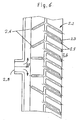
- FIG. 6 shows a with respect to a low-resistance flow in the Retarderkernring Scheme advantageously designed Retardereintritts Switzerland.
- a partial region of the stator 2.2 of the retarder 2 is shown in a developed view.
- the stator 2.2 has a plurality of stator blades 2.7.
- a predetermined number of stator blades 2.7 are provided with a bore 2.3 for supplying working fluid into the working space of the retarder 2.4.
- every second stator blade 2.7 has such a bore 2.3.
- each stator blade would have a corresponding bore.
- Stator blades with bores are also called filling blades.
- the entry into the Retarderkernring Scheme corresponds to the stator outlet, that is, the outlet of the working medium from the holes 2.3 in the filling blades.
- the working medium inlet side 2.5 On the working medium inlet side 2.5, the working medium flows through a central bore 2.8 over the entire circumference of the stator 2.2.
- a number of guide elements 2.6 are provided on the stator inlet side.
- FIG. 7 shows a further measure for aerodynamic design of the retardation entry area.
- two parallel bores 2.3 are introduced for feeding working medium into the working space of the retarder.
- the inlet channel 2.9 in the stator housing 2.10 which is designed as an annular channel (see the indicated dot-dashed center line).
- the stator is provided on its inlet side with guide elements 2.6.
- an outlet channel 2.11 Radially outside the inlet channel 2.9 designed as an annular channel, an outlet channel 2.11, likewise designed as an annular channel, is provided in the stator housing 2.10 in order to remove working medium from the retarder working space via a retarder outlet.
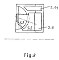
- FIGS. 8 to 11 show further flow resistance reducing measures in the area of the filling blades. So are in accordance with the FIG. 8 the holes 2.3 running in the filling blades of the stator as a conically tapered channel, the inlet opening in the region of the guide element 2.6 almost over the entire Height of the inlet channel 2.9 extends and in the region of the stator outlet side has the shape of a slot or a rectangle.
- FIG. 9 shows a combination of a conically tapered inlet channel with two holes, the inlet channel merges into the two holes.
- FIG. 10 shows an inlet channel, which merges into four stator blade holes.
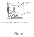
- FIG. 11 an initially conically tapered channel in the stator blade, which then merges in the flow direction into a channel with a constant cross-section.
Description
Die Erfindung betrifft einen Kühlmittelkreislauf eines Kraftfahrzeugs, welcher sowohl eine Kühlmittelpumpe als auch einen Retarder umfasst, wobei das Arbeitsmedium des Retarders das Kühlmittel ist.The invention relates to a coolant circuit of a motor vehicle, which comprises both a coolant pump and a retarder, wherein the working medium of the retarder is the coolant.
Herkömmlich wurde als Arbeitsmedium eines Retarders im Antriebsstrang eines Kraftfahrzeugs ein Hydrauliköl verwendet. Aufgrund der im Bremsbetrieb entstehenden Wärme musste das Hydrauliköl gekühlt werden. Dazu war in der Regel ein Öl-Wasser-Wärmetauscher als Schnittstelle zwischen Kühlkreislauf und Retarderarbeitsmediumkreislauf vorgesehen, über welchen die notwendige Wärmemenge aus dem Retarderkreislauf in den Kühlkreislauf des Fahrzeugs abgeführt wurde.Conventionally, a hydraulic oil was used as the working medium of a retarder in the drive train of a motor vehicle. Due to the heat generated during braking operation, the hydraulic oil had to be cooled. For this purpose, an oil-water heat exchanger was provided as an interface between the cooling circuit and Retarderarbeitsmediumkreislauf usually through which the necessary amount of heat was removed from the retarder circuit in the cooling circuit of the vehicle.
In jüngerer Zeit sind auch Retarder bekannt geworden, die unmittelbar im herkömmlichen Kühlmittelkreislauf des Fahrzeugs angeordnet sind und deren Arbeitsmedium das Kühlmedium des Kühlkreislaufs ist. Durch das Vorsehen solcher Retarder im Kühlkreislauf kann der Gesamtströmungswiderstand beziehungsweise der Durchflusswiderstand des Kühlmittels im Kühlkreislauf erhöht werden.More recently, retarders have become known which are arranged directly in the conventional coolant circuit of the vehicle and whose working fluid is the cooling medium of the cooling circuit. By providing such retarders in the cooling circuit, the total flow resistance or the flow resistance of the coolant in the cooling circuit can be increased.
Eines solche Gesamtströmungswiderstandserhöhung findet in erheblichem Ausmaß auch bei sogenannten Ölretardern aufgrund der zusätzlichen Bauteile im Kühlmittelkreislauf, beispielsweise des Öl-Wasser-Wärmetauschers, statt. Diese Strömungswiderständserhöhung hat Nachteile. Entsprechend kann keine herkömmlich dimensionierte Kühlmittelpumpe eingesetzt werden, wie sie bei Kühlkreisläufen ohne Retarder Verwendung findet, sondern eine leistungsstärkere Kühlmittelpumpe muss verwendet werden.Such a Gesamtströmungswiderstandserhöhung found to a considerable extent in so-called oil retarders due to the additional components in the coolant circuit, such as the oil-water heat exchanger instead. This flow resistance increase has disadvantages. Accordingly, no conventionally sized coolant pump can be used, as it is used in cooling circuits without retarder, but a more powerful coolant pump must be used.
Der Antrieb der leistungsstärkeren Kühlmittelpumpe erfordert mehr Energie, was zu erhöhtem Kraftstoffverbrauch des Kraftfahrzeugs führt. Dies fällt besonders dadurch ins Gewicht, dass diese erhöhte Leistungsaufnahme der Kühlmittelpumpe auch dann vorliegt, wenn der Retarder überhaupt nicht eingeschaltet ist, beispielsweise wenn er entleert ist. Der Retarder ist aber in der Regel nur zu einem relativ geringen Zeitraum gegenüber dem normalen Fahrbetrieb (ohne Bremsung des Fahrzeugs mit dem Retarder) eingesetzt. Schließlich bedeutet eine leistungsstärkere Kühlmiftelpumpe ein zusätzliches Fahrzeuggewicht, was ebenfalls zu einem erhöhten Kraftstoffverbrauch führt.The drive of the more powerful coolant pump requires more energy, resulting in increased fuel consumption of the motor vehicle. This is particularly significant in that this increased power consumption of the coolant pump is also present when the retarder is not turned on, for example, when it is empty. However, the retarder is usually only used for a relatively small period of time compared to the normal driving operation (without braking the vehicle with the retarder). Finally, a more powerful coolant pump means additional vehicle weight, which also leads to increased fuel consumption.
Der Erfindung liegt dia Aufgabe zugrunde, einen Kühlmittelkreislauf mit einer Kühlmittelpumpe und einem Retarder darzustellen, der gegenüber dem Stand der Technik verbessert ist. Insbesondere soll eine Kühlmittelpumpe verwendet werden können, weiche keine stärkere Leistungsaufnahme beziehungsweise Leistungsabgabe als Kühlmittelpumpen in Kühlkreisläufen ohne Retarder erfordert.The invention is based on the object to represent a coolant circuit with a coolant pump and a retarder, which is improved over the prior art. In particular, it should be possible to use a coolant pump which does not require any greater power consumption or power output than coolant pumps in cooling circuits without a retarder.
Die erfindungsgemäße Aufgabe wird durch die Merkmale des Anspruchs 1 gelöst. Die Unteransprüche beschreiben besonders vorteilhafte Ausführungen.The object of the invention is achieved by the features of
Die Erfindung und ihre Vorteile gegenüber dem Stand der Technik werden nachfolgend anhand der Figuren erläutert, wobei die
Im Einzelnen zieigen ;
Figur 1- eine schematische Darstellung eines Kraftfahrzeugskühlkreislaufes mit einem getrennt angeordneten Retarderarbeitsmediumkreislauf mit einem Ölretarder;
Figur 2- eine erste Ausführung eines erfindungsgemäßen Kühlmittelkreislaufs;
Figur 3- eine zweite Ausführung eines erfindungsgemäßen Kühlmittelkreislaufs;
Figur 4- eine dritte Ausführung eines erfindungsgemäßen Kühlmittelkreislaufs;
- Fig. 5a, 5b
- eine geschnittene Darstellung durch ein Umschaltventil;
- Figur 6
- eine abgewickelte Darstellung des Stators eines Retarders;
- Figur 7
- eine vorteilhafte Ausgestaltung von Bohrungen in Retarderfüllschaufeln;
- Figur 8
- eine weitere Ausgestaltung der Bohrung in einer Retarderfüllschaufel;
- Figur 9
- eine dritte mögliche Ausgestaltung der Bohrungen in einer Retarderfüllschaufel;
Figur 10- eine vierte mögliche Ausgestaltung von Bohrungen in einer Retarderfüllschaufel;
Figur 11- eine fünfte mögliche Ausgestaltung der Bohrungen in einer Retarderfüllschaufel.
- FIG. 1
- a schematic representation of a motor vehicle cooling circuit with a separately arranged Retarderarbeitsmedkreiskreislauf with an oil retarder;
- FIG. 2
- a first embodiment of a coolant circuit according to the invention;
- FIG. 3
- a second embodiment of a coolant circuit according to the invention;
- FIG. 4
- a third embodiment of a coolant circuit according to the invention;
- Fig. 5a, 5b
- a sectional view through a switching valve;
- FIG. 6
- a developed view of the stator of a retarder;
- FIG. 7
- an advantageous embodiment of holes in Retarderfüllschaufeln;
- FIG. 8
- a further embodiment of the bore in a Retarderfüllschaufel;
- FIG. 9
- a third possible embodiment of the holes in a Retarderfüllschaufel;
- FIG. 10
- a fourth possible embodiment of holes in a Retarderfüllschaufel;
- FIG. 11
- a fifth possible embodiment of the holes in a Retarderfüllschaufel.
In der
Von der Pumpe 1 wird der zum Energietransport notwendige Kühlmediumstrom, insbesondere Kühlwasserstrom, über den Motor 5, den wasserführenden Teil des Öl-Wasser-Wärmetauschers 12, über das Thermostat 15 und über den Wasser-Luft-Kühler 12 zur Saugseite der Pumpe 1 bewegt. Bei diesem Umlauf sind von der Pumpe 1 die im Kreislauf gegebenen Strömungswiderstände zu überwinden, das heißt, die Pumpe muss so viel Leistung aufnehmen bzw. abgeben, dass der Druck des Arbeitsmediums aufgrund des durch die Pumpe erzeugten Druckniveaus am Pumpenausgang 1.1 so weit über dem saugseitigen . Druckniveau liegt, dass sich eine entsprechende Kreislaufströmung durch den gesamten Kühlmittelkreislauf einstellt.From the
Zusätzliche Widerstände im Kühlmittelkreislauf senken und behindern den umlaufenden Kühlwasserstrom und damit die effektiv übertragbare Wärmemenge oder benötigen bei gleichem Kühlwasserstrom eine stärkere Pumpe mit dem Ergebnis einer erhöhten Leistungsaufnahme. Eine solche erhöhte Leistungsaufnahme führt zu einem vermehrten Kraftstoffverbrauch, was unerwünscht ist.Additional resistances in the coolant circuit reduce and hinder the circulating cooling water flow and thus the amount of heat that can be effectively transferred, or require a stronger pump with the same cooling water flow, resulting in increased power consumption. Such increased power consumption leads to increased fuel consumption, which is undesirable.
Einen solchen zusätzlichen Widerstand stellt beispielsweise der Öl-Wasser-Wärmetauscher 12 dar. Wenn man bedenkt, dass der Retarder nur während ca. 10 Prozent des Fahrzeugeinsatzes zum Bremsen notwendig ist, bedeuten die restlichen 90 Prozent des Fahrzeugeinsatzes einen Pumpenbetrieb mit unnötig hoher Leistungsaufnahme.Such an additional resistance, for example, the oil-
Die
Wie man sieht, ist der Retarder 2 unmittelbar im Kühlmittelkreislauf angeordnet und-durch die Bypassstrecke 4 umgehbar. In Strömungsrichtung vor dem Retarder 2 ist zum Steuern der Strömung - entweder durch den Retarder 2 oder durch den Bypass 4 - ein Umschaltventil 3 angeordnet.As you can see, the
Die vor dem Umschaltventil 3 angeordnete Kühlmittelpumpe 1 entspricht in ihrem Leistungsbereich einer Kühlmittelpumpe eines Kühlmittelkreislaufs ohne direkt eingebrachten Retarder oder ohne eingebrachten Öl-Wasser-Wärmetauscher für einen separaten Retarderkreislauf, wie er in der
Im Retarderbremsbetrieb ist der Strömungswiderstand zwischen Pumpenauslass 1.1 und einer Position im Kernring des Retarders 2 derart ausgelegt, dass er unterhalb des zuvor beschriebenen Gesamtströmungswiderstandes des Kühlmittelkreislaufes im Nichtbremsbetrieb liegt. Somit ist die Leistung der Pumpe 1 ausreichend, um einen ausreichenden Überlagerungsdruck für den Retarder 2 zur Verfügung zu stellen, so dass dieser die restliche Pumpenarbeit zur Umwälzung des Kühlmittels im Kühlmittelkreislauf 10 bis hin zur Saugseite der Pumpe 1 übernimmt. Ein Aspekt der dargestellten Ausführung ist somit darin zu sehen, dass die Pumpe 1 nur die Widerstandsstrecke vom Kühlmittelauslass 1.1 der Pumpe bis zum Retarder 2, das heißt genau gesagt bis zum Kenring des Retarders 2, überwindet. Der Strömungswiderstand im restlichen Kühlmittelkreislauf wird vom zugeschalteten Retarder überwunden. Dieses ist leicht möglich, wenn man bedenkt, dass die Kühlmittelpumpe einen Leistungsbereich gegenüber dem Leistungsbereich des Retarders hinsichtlich der möglichen Pumpleistung im Verhältnis von 1:100 aufweist. Beispielsweise weist die Pumpe eine Leistung von ca. 6 Kilowatt und der Retarder einen Leistungsbereich von 500 bis 600 Kilowatt auf.In Retarderbremsbetrieb the flow resistance between the pump outlet 1.1 and a position in the core ring of the
Dadurch, dass erfindungsgemäß der von der Kühlmittelpumpe 1 zu überwindende Strömungswiderstand im Bremsbetrieb geringer ist als im Nichtbremsbetrieb, stellt sich eine erhöhte Umlaufmenge an Kühlmedium ein. Dies ist gerade im Retarderbremsbetrieb von Vorteil, um die thermische Verfügbarkeit eines derartigen Bremssystems zu erhöhen und damit den möglichen verschleißfreien Bremsbetrieb vergleichsweise zu erweitern, was zur Entlastung von im Fahrzeug vorgesehenen Verschleißbremsen führt. Dadurch, dass der Retarder in Strömungsrichtung vor dem zu kühlenden Motor 5 angeordnet ist, kann einmal der von der Kühlmittelpumpe zu überwindende Strömungswiderstand besonders gering gehalten werden, was den Durchsatz bei gleicher Drehzahl erhöht, und zum anderen weist das Arbeitsmedium im Retarder eine relativ geringe Temperatur auf.Due to the fact that, according to the invention, the flow resistance to be overcome by the
In der
Vorteil dieser Ausführung ist, dass das im Retarder erwärmte Kühlmittel unmittelbar nachfolgend im Fahrzeugkühler 12 gekühlt wird. Bei entsprechender Ausbildung des Retarders können Kühlmitteltemperaturen zugelassen werden, welche oberhalb der zulässigen Kühlmitteleintrittstemperaturen am Motor 5 liegen.Advantage of this embodiment is that the heated coolant in the retarder is cooled immediately below in the
Bei der gezeigten Ausführung gemäß der
Die Anordnung gemäß der
In der
Auch in dieser Ausführung ist die Strömungsführung vom Auslass 1.1 der Kühlmittelpumpe 1 bis zum Kernring des Retarders 2 derart gestaltet, dass der Strömungswiderstand dieser Strecke geringer ist als der Strömungswiderstand im Nichtbremsbetrieb des gesamten Kühlmittelkreislaufs 10.Also in this embodiment, the flow guide from the outlet 1.1 of the
Besonders vorteilhaft kann bei allen gezeigten Ausführungen eine Anpassung des Strömungswiderstandes zwischen Pumpenauslass 1.1 und Kernring des Retarders 2 durch eine vorgegebene Anzahl von Bohrungen im Befüllsystem des Retarders vorgenommen werden. Die Anzahl und/oder Größe der Bohrungen beziehungsweise der jeweiligen Befüllquerschnitte sind vorteilhaft gemäß den jeweiligen Widerstandscharakteristiken des verwendeten Fahrzeugkühlsystems ausgewählt.Particularly advantageously, in all the embodiments shown, an adaptation of the flow resistance between the pump outlet 1.1 and the core ring of the
Nachfolgend werden einige Ausführungen zur Einstellung eines besonders niedrigen Strömungswiderstands dargelegt.In the following, some embodiments for setting a particularly low flow resistance are presented.
Die
Ferner weist das Umschaltventil 3 einen zylindrischen Ventilkolben 3.4 auf, welcher um seine Längsachse drehbar ist. Der zylindrische Ventilkolben weist Radialbohrungen auf, nämlich eine Auslassbohrung 3.5 und eine Einlassbohrung 3.6. Die Auslassbohrung 3.5 ist beispielsweise zylindrisch ausgeführt, während die Einlassbohrung 3.6 konisch verjüngt beziehungsweise trichterförmig ausgeführt ist. Eine, beide oder mehrere Bohrungen können selbstverständlich in ihrem Querschnitt auch andere Formen aufweisen, beispielsweise die eines Langlochs. Durch Drehen des zylindrischen Ventilkolbens 3.4 um seine Längsachse wird der Einlass 3.1 mit einem der beiden Auslässe 3.2 und 3.3 gezielt verbunden.Further, the switching
Bei der oben beschriebenen Verschaltung der Auslässe 3.2 und 3.3 ist in der
Die konisch verjüngte Einlassbohrung 3.6 weist eine derartig dimensionierte Einlassöffnung am Umfang des Ventilkolbens 3.4 auf, das ungeachtet der Stellung des Ventilkolbens 3.4 - das heißt ungeachtet dessen, ob dieser den Einlass 3.1 mit dem Auslass 3.2 strömungsleitend verbindet oder den Einlass 3.1 mit dem Auslass 3.3 - die Einlassöffnung der Einlassbohrung 3.6 den Strömungsquerschnitt des Einlasses 3.1 vollständig umschließt.The conically tapered inlet bore 3.6 has such a dimensioned inlet opening on the circumference of the valve piston 3.4, regardless of the position of the valve piston 3.4 - that is regardless of whether this connects the inlet 3.1 with the outlet 3.2 in flow-conducting or the inlet 3.1 with the outlet 3.3 - the inlet opening of the inlet bore 3.6 completely encloses the flow cross-section of the inlet 3.1.
Durch die gezeigte Gestaltung des Drehschiebers wird eine äußerst strömungsgünstige und widerstandsarme Lösung erreicht.The illustrated design of the rotary valve an extremely streamlined and low-resistance solution is achieved.
Die
Der Stator 2.2 weist eine Vielzahl von Statorschaufeln 2.7 auf. Eine vorbestimmte Anzahl von Statorschaufeln 2.7 sind mit einer Bohrung 2.3 zum Zuführen von Arbeitsmedium in den Arbeitsraum des Retarders 2.4 versehen. In der gezeigten Ausführung weist jede zweite Statorschaufel 2.7 eine solche Bohrung 2.3 auf. In einem Extremfall würde jede Statorschaufel eine entsprechende Bohrung aufweisen. Statorschaufeln mit Bohrungen werden auch als Füllschaufeln bezeichnet.The stator 2.2 has a plurality of stator blades 2.7. A predetermined number of stator blades 2.7 are provided with a bore 2.3 for supplying working fluid into the working space of the retarder 2.4. In the embodiment shown, every second stator blade 2.7 has such a bore 2.3. In an extreme case, each stator blade would have a corresponding bore. Stator blades with bores are also called filling blades.
Der Eintritt in den Retarderkernringbereich entspricht dem Statoraustritt, das heißt dem Austritt des Arbeitsmediums aus den Bohrungen 2.3 in den Füllschaufeln.The entry into the Retarderkernringbereich corresponds to the stator outlet, that is, the outlet of the working medium from the holes 2.3 in the filling blades.
Auf der Arbeitsmediumeintrittsseite 2.5 strömt das Arbeitsmedium über eine Zentralbohrung 2.8 über den gesamten Umfang des Stators 2.2. Um eine besonders gleichmäßige Verteilung des Zulaufstroms über den gesamten Umfang zu erreichen, sind auf der Statoreintrittsseite eine Anzahl von Leitelementen 2.6, insbesondere in Form von Rippen, vorgesehen.On the working medium inlet side 2.5, the working medium flows through a central bore 2.8 over the entire circumference of the stator 2.2. To one To achieve a particularly uniform distribution of the feed stream over the entire circumference, a number of guide elements 2.6, in particular in the form of ribs, are provided on the stator inlet side.
Durch die gleichmäßige Verteilung des durch die Zentralbohrung 2.8 eintretenden Arbeitsmediums über den gesamten Statorumfang und damit gleichmäßig auf alle Füllschaufeln, insbesondere auf jede oder jede zweite Statorschaufel, wird eine besonders widerstandsarme Strömung bis zum Kernring des Retarders, das heißt bis zum Statoraustritt, erreicht.Due to the uniform distribution of the entering through the central bore 2.8 working medium over the entire stator circumference and thus evenly on all Füllschaufeln, in particular every or every second Statorschaufel, a particularly low-resistance flow to the core ring of the retarder, that is to the stator outlet, achieved.
Die
Es ist jedoch nicht notwendig, den Ringkanal rotationssymmetrisch gegenüber der Mittellinie auszuführen, auch abweichende Formen, beispielsweise begründet durch den am Getriebe zur Verfügung stehenden Bauraum, können ausgeführt werden.However, it is not necessary to perform the annular channel rotationally symmetrical with respect to the center line, and deviating forms, for example, based on the space available on the transmission, can be performed.
Radial außerhalb des als Ringkanal ausgebildeten Einlasskanals 2.9 ist ein ebenfalls als Ringkanal ausgebildeter Auslasskanal 2.11 im Statorgehäuse 2.10 vorgesehen, um Arbeitsmedium aus dem Retarderarbeitsraum über einen Retarderauslass abzuführen.Radially outside the inlet channel 2.9 designed as an annular channel, an outlet channel 2.11, likewise designed as an annular channel, is provided in the stator housing 2.10 in order to remove working medium from the retarder working space via a retarder outlet.
Die
Die
Die
Schließlich zeigt die
Claims (5)
- A coolant circuit of a motor vehicle, comprising1.1 a coolant;1.2 a coolant pump (1) having a coolant outlet (1.1);1.3 a retarder (2), which has a stator (2.2) and a core ring and whose working medium is the coolant, the core ring corresponding to the part of the working space (2.4) of the retarder (2) which is arranged behind a coolant-guiding retarder intake region in the flow direction of the coolant;1.4 a changeover valve (3) in the flow direction before the retarder (2) and a bypass route (4) for bypassing the retarder (2), so that the retarder (2) is switchable in and out with respect to the coolant circuit; whereby1.5 the coolant pump (1) is arranged in the flow direction before the retarder (2) in such a manner that it pumps coolant into the retarder (2) when the retarder (2) is switched in and it pumps coolant through the bypass route (4) past the retarder (2) when the retarder (2) is switched out, and whereby1.6 the total flow resistance from the outlet (1.1) of the coolant pump (1) up to the core ring of the retarder (2) when the retarder is switched in is less than the cumulative flow resistance of the coolant circuit to be overcome by the coolant pump (1) in non-braking operation, in that1.6.1 the coolant pump (1), the changeover valve (3), and the retarder (2) are arranged in direct succession in the flow direction in the mentioned sequence in the coolant circuit when the retarder is switched in, and/or1.6.2 the stator (2.2) of the retarder (2) has bores (2.3) for supplying working medium into the working space (2.4) of the retarder (2) and is provided on its working medium intake side (2.5) over its entire circumference with ribs (2.6) for uniform distribution of the working medium over the stator circumference; and/or1.6.3 the stator (2.2) of the retarder (2) has bores (2.3) for supplying the working medium into the working chamber (2.4) of the retarder (2), the bores (2.3) are conically tapered in the flow direction, and/or1.6.4 the stator (2.2) of the retarder (2) has bores (2.3) for supplying the working medium into the working space (2.4) of the retarder (2), which are implemented in a plurality of predefined blades (2.7), whereby multiple bores (2.3) are provided per bored blade (2.7).
- The coolant circuit according to Claim 1, characterized in that an engine (5) to be cooled, in particular an internal combustion engine, is arranged in the coolant circuit before the retarder (2) and after the coolant pump (1) in the flow direction when the retarder (2) is switched in.
- The coolant circuit according to one of Claims 1 or 2, characterized in that an engine (5) to be cooled, in particular an internal combustion engine, is arranged in the coolant circuit after the retarder (2) and before the coolant pump (1) in the flow direction when the retarder (2) is switched in.
- The coolant circuit according to one of Claims 1 to 3, characterized in that the retarder (2) is a secondary retarder.
- The coolant circuit according to one of Claims 1 to 4, characterized in that the changeover valve (3) is implemented as a rotary slide valve, which comprises one inlet (3.1) and two outlets (3.2, 3.3) and
has a cylindrical valve piston (3.4) rotatable around its longitudinal axis, which
comprises an outlet bore (3.5), which is introduced in the radial direction into the valve piston (3.4) and can be aligned flush with each of the outlets (3.2, 3.3) by rotating the valve piston; and furthermore an inlet bore (3.6), which is introduced in the radial direction into the valve piston (3.4) and is connected to the outlet bore (3.5) to conduct flow, whereby
the inlet bore (3.6) is implemented as conically tapering radially from the outside to the inside, whereby the radial outer opening surface has such an enlarged diameter that it continuously has a flow-conducting connection to the inlet (3.1) despite the alignment of the outlet bore (3.5) with an outlet (3.2, 3.3).
Applications Claiming Priority (2)
| Application Number | Priority Date | Filing Date | Title |
|---|---|---|---|
| DE10332907A DE10332907A1 (en) | 2003-07-19 | 2003-07-19 | Automotive coolant circuit with pump and retarder |
| PCT/EP2004/007546 WO2005014985A1 (en) | 2003-07-19 | 2004-07-09 | Motor vehicle coolant circuit comprising a pump and a retarder |
Publications (2)
| Publication Number | Publication Date |
|---|---|
| EP1646771A1 EP1646771A1 (en) | 2006-04-19 |
| EP1646771B1 true EP1646771B1 (en) | 2012-09-12 |
Family
ID=34071790
Family Applications (1)
| Application Number | Title | Priority Date | Filing Date |
|---|---|---|---|
| EP04740833A Expired - Fee Related EP1646771B1 (en) | 2003-07-19 | 2004-07-09 | Motor vehicle coolant circuit comprising a pump and a retarder |
Country Status (8)
| Country | Link |
|---|---|
| US (1) | US20070131181A1 (en) |
| EP (1) | EP1646771B1 (en) |
| JP (1) | JP4767847B2 (en) |
| KR (1) | KR100740267B1 (en) |
| CN (1) | CN1826458B (en) |
| DE (1) | DE10332907A1 (en) |
| RU (1) | RU2347085C2 (en) |
| WO (1) | WO2005014985A1 (en) |
Cited By (2)
| Publication number | Priority date | Publication date | Assignee | Title |
|---|---|---|---|---|
| DE102013001657A1 (en) | 2013-01-31 | 2014-07-31 | Man Truck & Bus Ag | Cooling circuit for a motor vehicle with a hydrodynamic retarder |
| DE102017001882A1 (en) | 2017-02-27 | 2018-07-19 | Audi Ag | Distributor device for distributing a fluid medium |
Families Citing this family (18)
| Publication number | Priority date | Publication date | Assignee | Title |
|---|---|---|---|---|
| DE102004061428A1 (en) * | 2004-12-21 | 2006-06-29 | Daimlerchrysler Ag | Cooling circuit for a motor vehicle and control method therefor |
| EP2021666B8 (en) * | 2006-05-15 | 2018-01-03 | Thomas J. Hollis | Digital rotary control valve |
| DE102007006420A1 (en) * | 2007-02-05 | 2008-08-07 | Voith Patent Gmbh | Motor vehicle drive train of a motor vehicle with a compressed air system |
| DE102009005504A1 (en) * | 2009-01-19 | 2010-07-22 | Voith Patent Gmbh | Vehicle cooling circuit with a retarder or a hydrodynamic coupling |
| DE102010051715A1 (en) * | 2010-11-19 | 2012-05-24 | Voith Patent Gmbh | Powertrain with a hydrodynamic retarder |
| DE102011116933A1 (en) | 2011-10-26 | 2013-05-02 | Man Truck & Bus Ag | Cooling circuit for a liquid-cooled engine |
| CN103863271B (en) * | 2012-12-12 | 2016-11-23 | 北汽福田汽车股份有限公司 | The cooling system of vehicle |
| CN103481871B (en) * | 2013-10-15 | 2015-07-22 | 江苏理工学院 | Cooling-liquid medium type hydraulic retarding device for vehicle |
| CN103486164B (en) * | 2013-10-15 | 2015-07-22 | 江苏理工学院 | Hydraulic speed retarding device adopting engine oil as medium |
| SE538626C2 (en) * | 2013-10-24 | 2016-10-04 | Scania Cv Ab | Cooling system in a vehicle |
| DE102014201167A1 (en) | 2014-01-23 | 2015-07-23 | Bayerische Motoren Werke Aktiengesellschaft | Thermal management system for an internal combustion engine |
| WO2015168313A1 (en) * | 2014-04-30 | 2015-11-05 | Cummins Inc. | System and method for optimizing the integration of engines and vehicle driveline retarders |
| KR101642315B1 (en) * | 2015-04-08 | 2016-07-26 | 한국파워트레인 주식회사 | Feeding control apparatus for fluid retarder |
| CN105756763B (en) * | 2016-03-14 | 2018-10-16 | 潍柴动力股份有限公司 | A kind of cooling system of vehicle and its control method, the vehicle equipped with the system |
| DE102016011481A1 (en) | 2016-09-22 | 2018-03-22 | Daimler Ag | Vehicle seat for a motor vehicle and motor vehicle |
| CN110566604A (en) * | 2019-09-23 | 2019-12-13 | 陕西法士特齿轮有限责任公司 | Retarder main circulation system |
| DE102019133947A1 (en) * | 2019-12-11 | 2020-12-31 | Voith Patent Gmbh | Cooling system |
| CN113323973B (en) * | 2021-06-29 | 2022-01-28 | 吉林大学 | Hydraulic retarder with rotor with device for reducing no-load loss |
Family Cites Families (11)
| Publication number | Priority date | Publication date | Assignee | Title |
|---|---|---|---|---|
| US2287130A (en) * | 1941-02-26 | 1942-06-23 | Parkersburg Rig & Reed Company | Hydrodynamic brake mechanism |
| DE1530672A1 (en) | 1963-09-03 | 1969-10-30 | Eaton Yale & Towne | Hydrodynamic braking device for motor vehicles |
| US3185261A (en) * | 1963-10-25 | 1965-05-25 | Caterpillar Tractor Co | Wheel driven hydrodynamic retarder system |
| US3721265A (en) * | 1971-04-29 | 1973-03-20 | Fmc Corp | Three-way valve |
| DE3831596A1 (en) * | 1988-09-14 | 1990-03-22 | Mannesmann Ag | Hydraulic brake, particularly for power test stands |
| DE4416039C1 (en) * | 1994-05-06 | 1995-08-31 | Freudenberg Carl Fa | Mixer control valve |
| EP0794326A1 (en) * | 1996-03-08 | 1997-09-10 | Voith Turbo GmbH & Co. KG | Drive unit with an engine and a retarder |
| US6561324B2 (en) * | 1996-03-08 | 2003-05-13 | Voith Turbo Gmbh & Co. Kg | Drive unit including a motor and a retarder |
| DE19641557A1 (en) * | 1996-10-09 | 1997-06-26 | Voith Turbo Kg | Drive unit with internal combustion engine, transmission and coolant circuit |
| DE19848544C1 (en) * | 1998-10-22 | 2000-06-21 | Voith Turbo Kg | Method and device for increasing the braking torque utilization of a hydrodynamic retarder in a motor vehicle |
| US6539899B1 (en) * | 2002-02-11 | 2003-04-01 | Visteon Global Technologies, Inc. | Rotary valve for single-point coolant diversion in engine cooling system |
-
2003
- 2003-07-19 DE DE10332907A patent/DE10332907A1/en not_active Withdrawn
-
2004
- 2004-07-09 KR KR1020067000202A patent/KR100740267B1/en not_active IP Right Cessation
- 2004-07-09 WO PCT/EP2004/007546 patent/WO2005014985A1/en active Application Filing
- 2004-07-09 CN CN2004800207251A patent/CN1826458B/en not_active Expired - Fee Related
- 2004-07-09 EP EP04740833A patent/EP1646771B1/en not_active Expired - Fee Related
- 2004-07-09 US US10/565,015 patent/US20070131181A1/en not_active Abandoned
- 2004-07-09 JP JP2006519838A patent/JP4767847B2/en not_active Expired - Fee Related
- 2004-07-09 RU RU2006105016/06A patent/RU2347085C2/en not_active IP Right Cessation
Cited By (4)
| Publication number | Priority date | Publication date | Assignee | Title |
|---|---|---|---|---|
| DE102013001657A1 (en) | 2013-01-31 | 2014-07-31 | Man Truck & Bus Ag | Cooling circuit for a motor vehicle with a hydrodynamic retarder |
| WO2014118158A1 (en) | 2013-01-31 | 2014-08-07 | Man Truck & Bus Ag | Cooling circuit for a motor vehicle having a hydrodynamic retarder |
| US9650023B2 (en) | 2013-01-31 | 2017-05-16 | Man Truck & Bus Ag | Cooling circuit for a motor vehicle having a hydrodynamic retarder |
| DE102017001882A1 (en) | 2017-02-27 | 2018-07-19 | Audi Ag | Distributor device for distributing a fluid medium |
Also Published As
| Publication number | Publication date |
|---|---|
| JP2007526848A (en) | 2007-09-20 |
| RU2006105016A (en) | 2006-06-27 |
| EP1646771A1 (en) | 2006-04-19 |
| DE10332907A1 (en) | 2005-02-17 |
| RU2347085C2 (en) | 2009-02-20 |
| US20070131181A1 (en) | 2007-06-14 |
| KR100740267B1 (en) | 2007-07-18 |
| WO2005014985A1 (en) | 2005-02-17 |
| JP4767847B2 (en) | 2011-09-07 |
| CN1826458B (en) | 2011-06-15 |
| KR20060030104A (en) | 2006-04-07 |
| CN1826458A (en) | 2006-08-30 |
Similar Documents
| Publication | Publication Date | Title |
|---|---|---|
| EP1646771B1 (en) | Motor vehicle coolant circuit comprising a pump and a retarder | |
| EP0719683B1 (en) | Brake system with hydrodynamic retarder, especially for motor vehicle | |
| EP1702820B1 (en) | Cooling circuit with a retarder | |
| EP2379384B1 (en) | Vehicle cooling circuit having a retarder or a hydrodynamic clutch | |
| WO2004026651A1 (en) | Drive unit comprising a retarder | |
| EP0671302A1 (en) | Drive unit with an engine and a retarder | |
| EP2951066B1 (en) | Cooling circuit for a motor vehicle having a hydrodynamic retarder | |
| DE102012019459A1 (en) | Temperature control device for vehicle e.g. passenger car, has supplementary heating unit arranged at and/or in bypass of control circuit, which interconnects heat forward and heat return flows of space heating unit with each other | |
| DE69829374T2 (en) | METHOD AND DEVICE FOR A CIRCULATING PUMP | |
| DE102011015196B4 (en) | Heating for heating vehicle consumables and corresponding rail vehicle | |
| DE102013219786A1 (en) | Hydraulic system for a hydrodynamic machine | |
| DE102015201240A1 (en) | Split cooling system and internal combustion engine with a split cooling system and vehicle equipped accordingly | |
| DE102015200052A1 (en) | Liquid-cooled internal combustion engine with shift gate and method for controlling the shift gate of such an internal combustion engine | |
| DE60118931T2 (en) | HYDRODYNAMIC BRAKE | |
| DE19637316A1 (en) | Drive unit with motor and retarder | |
| EP1586754B1 (en) | Cooling system | |
| WO2006066711A1 (en) | Cooling circuit for a motor vehicle and control method therefor | |
| DE3823474A1 (en) | Vehicle heating system having a heat store (accummulator) | |
| DE10150681B4 (en) | Hydrodynamic braking system with a retarder | |
| DE10138704A1 (en) | Cooling system for vehicle drive, has second cooling circuit divided into sub-circuits that can be used together or separately as required, e.g. for retarder, traction and engine braking operation | |
| DE10318711A1 (en) | Arrangement for driving coolant pump for internal combustion engine has planetary gear components, coupling and brake structurally integrated into common housing | |
| DE19951731A1 (en) | Retarder system | |
| WO1997033077A1 (en) | Drive unit with a motor and a retarder | |
| DE102008013675B4 (en) | Internal design of the housing of a coolant pump with multiple outlet channels | |
| WO2006027132A1 (en) | Cooling circuit for a motor vehicle and control method therefor |
Legal Events
| Date | Code | Title | Description |
|---|---|---|---|
| PUAI | Public reference made under article 153(3) epc to a published international application that has entered the european phase |
Free format text: ORIGINAL CODE: 0009012 |
|
| 17P | Request for examination filed |
Effective date: 20051126 |
|
| AK | Designated contracting states |
Kind code of ref document: A1 Designated state(s): DE |
|
| DAX | Request for extension of the european patent (deleted) | ||
| RBV | Designated contracting states (corrected) |
Designated state(s): DE |
|
| 17Q | First examination report despatched |
Effective date: 20101125 |
|
| GRAP | Despatch of communication of intention to grant a patent |
Free format text: ORIGINAL CODE: EPIDOSNIGR1 |
|
| GRAS | Grant fee paid |
Free format text: ORIGINAL CODE: EPIDOSNIGR3 |
|
| GRAA | (expected) grant |
Free format text: ORIGINAL CODE: 0009210 |
|
| AK | Designated contracting states |
Kind code of ref document: B1 Designated state(s): DE |
|
| REG | Reference to a national code |
Ref country code: DE Ref legal event code: R096 Ref document number: 502004013743 Country of ref document: DE Effective date: 20121108 |
|
| PLBE | No opposition filed within time limit |
Free format text: ORIGINAL CODE: 0009261 |
|
| STAA | Information on the status of an ep patent application or granted ep patent |
Free format text: STATUS: NO OPPOSITION FILED WITHIN TIME LIMIT |
|
| 26N | No opposition filed |
Effective date: 20130613 |
|
| REG | Reference to a national code |
Ref country code: DE Ref legal event code: R097 Ref document number: 502004013743 Country of ref document: DE Effective date: 20130613 |
|
| REG | Reference to a national code |
Ref country code: DE Ref legal event code: R082 Ref document number: 502004013743 Country of ref document: DE Ref country code: DE Ref legal event code: R081 Ref document number: 502004013743 Country of ref document: DE Owner name: VOITH PATENT GMBH, DE Free format text: FORMER OWNER: VOITH TURBO GMBH & CO. KG, 89522 HEIDENHEIM, DE |
|
| PGFP | Annual fee paid to national office [announced via postgrant information from national office to epo] |
Ref country code: DE Payment date: 20220620 Year of fee payment: 19 |
|
| REG | Reference to a national code |
Ref country code: DE Ref legal event code: R119 Ref document number: 502004013743 Country of ref document: DE |