US2287130A - Hydrodynamic brake mechanism - Google Patents
Hydrodynamic brake mechanism Download PDFInfo
- Publication number
- US2287130A US2287130A US380726A US38072641A US2287130A US 2287130 A US2287130 A US 2287130A US 380726 A US380726 A US 380726A US 38072641 A US38072641 A US 38072641A US 2287130 A US2287130 A US 2287130A
- Authority
- US
- United States
- Prior art keywords
- brake
- fluid
- water
- engine
- pipe
- Prior art date
- Legal status (The legal status is an assumption and is not a legal conclusion. Google has not performed a legal analysis and makes no representation as to the accuracy of the status listed.)
- Expired - Lifetime
Links
- 230000007246 mechanism Effects 0.000 title description 5
- 239000012530 fluid Substances 0.000 description 112
- XLYOFNOQVPJJNP-UHFFFAOYSA-N water Substances O XLYOFNOQVPJJNP-UHFFFAOYSA-N 0.000 description 86
- 239000007788 liquid Substances 0.000 description 63
- 230000009471 action Effects 0.000 description 42
- 239000012809 cooling fluid Substances 0.000 description 41
- 238000001816 cooling Methods 0.000 description 19
- 238000005086 pumping Methods 0.000 description 9
- 238000013021 overheating Methods 0.000 description 8
- 238000012856 packing Methods 0.000 description 6
- 238000004891 communication Methods 0.000 description 5
- 238000010276 construction Methods 0.000 description 5
- 238000012423 maintenance Methods 0.000 description 5
- 238000009434 installation Methods 0.000 description 4
- 239000000110 cooling liquid Substances 0.000 description 3
- 230000036961 partial effect Effects 0.000 description 3
- 238000013022 venting Methods 0.000 description 3
- 230000035508 accumulation Effects 0.000 description 2
- 238000009825 accumulation Methods 0.000 description 2
- 230000005540 biological transmission Effects 0.000 description 2
- 230000003247 decreasing effect Effects 0.000 description 2
- 239000000463 material Substances 0.000 description 2
- 230000002829 reductive effect Effects 0.000 description 2
- 238000012360 testing method Methods 0.000 description 2
- 208000027418 Wounds and injury Diseases 0.000 description 1
- 230000002411 adverse Effects 0.000 description 1
- 230000008901 benefit Effects 0.000 description 1
- 239000000969 carrier Substances 0.000 description 1
- 238000005266 casting Methods 0.000 description 1
- 150000001768 cations Chemical class 0.000 description 1
- 239000000498 cooling water Substances 0.000 description 1
- 230000006378 damage Effects 0.000 description 1
- 230000007812 deficiency Effects 0.000 description 1
- 230000001066 destructive effect Effects 0.000 description 1
- 230000003467 diminishing effect Effects 0.000 description 1
- 230000000694 effects Effects 0.000 description 1
- 230000008030 elimination Effects 0.000 description 1
- 238000003379 elimination reaction Methods 0.000 description 1
- 230000001939 inductive effect Effects 0.000 description 1
- 208000014674 injury Diseases 0.000 description 1
- 230000009467 reduction Effects 0.000 description 1
- 230000002441 reversible effect Effects 0.000 description 1
- -1 steam Substances 0.000 description 1
- 239000008400 supply water Substances 0.000 description 1
- 238000009834 vaporization Methods 0.000 description 1
- 230000008016 vaporization Effects 0.000 description 1
Images

Classifications
-
- F—MECHANICAL ENGINEERING; LIGHTING; HEATING; WEAPONS; BLASTING
- F16—ENGINEERING ELEMENTS AND UNITS; GENERAL MEASURES FOR PRODUCING AND MAINTAINING EFFECTIVE FUNCTIONING OF MACHINES OR INSTALLATIONS; THERMAL INSULATION IN GENERAL
- F16D—COUPLINGS FOR TRANSMITTING ROTATION; CLUTCHES; BRAKES
- F16D57/00—Liquid-resistance brakes; Brakes using the internal friction of fluids or fluid-like media, e.g. powders
- F16D57/04—Liquid-resistance brakes; Brakes using the internal friction of fluids or fluid-like media, e.g. powders with blades causing a directed flow, e.g. Föttinger type
Definitions
- This invention relates to hydrodynamic brake mechanisms for motor vehicles.
- Hydrodynamic brake and similar mechanisms have been developed to a point of high efficiency and numerous efiorts have been made to utilize such a mechanism in motor vehicles, particularly heavy trucks and buses, for the purpose of the speed of the vehicles on long down grades without the necessity of having to use the conventional vehicle friction brakes; It is well known, that the latter brakes have a relatively short life on large motor vehicles used in hilly and mountainous regions due to the constant wearing of the brakes on long down grades and due to the destructive efiects of the heat generated in the continued use of the brakes over substantial periods. r
- the hydrodynamic brake is supplied with water from the inlet side of the engine water pump but does not employ the threeway valve which prevents water from flowing to the engine. 0n the contrary, it governs the admission of water into the brake by means of a valved control associated with the brake itself whereby some of the water flows through the engine and some to the brake.
- This arrangement therefore, is desirable over other and previous arrangements, but all prior uses of hydrodynamic brakes on motor vehicles have been disadvantageous for the reason that a substantial amount of water is required in the brake and when the brake is in operation the water level of the vehicle cooling system necessarilydrops, thus causing the engine to overheat or at least to run above a preferred maximum temperature.
- An important object of the present invention is to provide a hydrodynamic braking system for motor vehicles wherein the' disadvantages of prior constructions referred to above are completely eliminated.
- an important object of the invention is to provide a hydrodynamic brake system for motor vehicles which utilizes the vehicle radiator as the means for cooling the liquid flowing through the brake, and wherein means is provided for preventing the level of the cooling fluid from dropping in the radiator, and thus avoiding the overheating of the motor.
- a further object is to provide such a braking system wherein the normal flow of engine cooling water from the radiator to the water .pump and thence through the engine water jacket is not disturbed in any way in pumping water to ter or other cooling and braking liquid is maintained in association with the liquid of the engine cooling system in such a manner as to provide an auxiliary liquid supply which is ample for taking care of the demands of the hydrodynamic brake without causing the liquid level in the cooling system to drop.
- a further object is to provide such a. system wherein the auxiliary liquid supply immediately compensates for the diminishing fiow of water from the engine to the radiator when the hydrodynamic brake is brought into action, thus maintaining the water level in the-radiator at the proper point.
- a further object is to provide a simplified valve control for determining the rate of flow of liquid to the brake andthus to determine the degree of braking action provided thereby.
- a further object is to provide a novel system which, under normal operating conditions, is
- a further object is to provide novel means for returning to the liquid system any liquid which leaks from the rotor and stator pockets in the tion and parts being broken away,
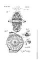
- FIG. 2 is a side elevation of the hydrodynamic brake, parts being shown in section,
- Figure 3 is a section on line 3-3 of Figure 2
- Figure 4 is a section on line 4-4 of Figure 3,
- Figure 5 is a detail sectional view of the threeway brake control valve.
- Figure 6 is a fragmentary elevation showing a means for venting the brake.
- the numeral 18 designates a portion of a conventional motor vehicle engine having the usual water jacket (not shown) to which inlet and outlet pipes I l and I2 respectively are connected.
- the pipe connection 12 leads through a three-way valve l3, to be described in detail later, and thence through a pipe i4 to a radiator l5 which may be conventional except for the elimination of the usual over-flow pipe, as will be referred to later.
- the lower portion of the radiator is connected by a pipe 18 to a conventional circulating pump l1 from which water or other cooling liquid flows through the pipe II to the jacket of the engine.
- a pipe l8 has one end leading into the radiator adjacent the top thereof from a surge tank indicated as a whole by the numeral I9 and to be described later.
- the third connection of the valve i3 has one end of a pipe 28' tapped thereinto and leads to the hydrodynamic brake indicated as a whole by the numeral 28.
- the hydrodynamic brake is shown in Figures 2,
- numerals 2i and 22 designate a pair of annular casing sections which form the stator elements of the brake as will become apparent.
- the casing section 22 is provided with an annular flange 23 projecting toward the casing section 2
- the two casing sections cooperate to form a circular rotor cavity 25 in which is arranged a rotor indicated as a whole by the numeral 26.
- the casing sections 2i and 22 are provided in their inner faces with radial cavities 21 for the radial flow of liquid in accordance with the conventional operation of a hydrodynamic brake.
- and 22 is provided with preferably integral water inlet tubes 28, the inner edges of which terminate in the plane of the walls of the cavity 25.
- the outer ends of these tubes communicate with annular water pockets 29 formed in the casing sections and communicating with'each other at the bottom of the brake as at 30.
- the liquid communicating space 30 is formed at the inner end of a tangential connection 3
- the rotor 25 is arranged in the rotor cavity 25 radial pockets 33 formed by radial vanes 34 as I shown in Figure 4.
- the thickness of the rotor is slightly less than the width of the rotor cavity 25 so as to provide a slight clearance between the rotor and stator elements.
- water flows through the tubes 28 into the pockets 33.
- Opposite pockets 33 preferably communicate with each other through openings 33' for a purpose to be described.
- the tubes 28 are preferably arranged so that rotation of the rotor will induce a flow of liquid into the brake pockets. This arrangement of the tubes 28 forms no part of the present invention, being disclosed in a number of prior patents, such, for example, as Patent No. 2,118,109, granted to Robert Griffln De La Mater.
- the rotor is mounted on a shaft 34' which may be connected in the propeller shaft of the motor vehicle to form a part thereof.
- the forward end of the shaft 34' may be directly connected to the driven shaft of the vehicle, or may be connectedto the driven shaft of the auxiliary transmission arranged rearwardly of the conventional transmission in soine trucks and buses.
- the brake unit may be substituted for the mid-ship bearing employed with many truck and bus propeller shafts.
- the rear end of the shaft 34' is directly connected by a shaft section to the conventional bearing diiferential.
- the shaft 34' is rotatable in roller bearings 35 mounted in carriers 38 supported in recesses 31 formed in the respective casing sections 2
- the rotor 28 carries a hub 38 keyed to the shaft as at 39.
- the hub 38 rotates in contact with packing rings 40 to provide as nearly leak-proof joints as possible to prevent water or other liquid in the brake from escaping axially from the brake.
- is preferably arranged to prevent any leakage water from reaching the bearings.
- packing rings 42 are preferably employed to prevent the entrance of any foreign material into the bearings.
- and 22 are respectively provided with leakage cavities 43 wholly separate and distinct from the liquid cavities 29 and extending downwardly from the rings 38 as indicated in dotted lines in Figure 2. Accordingly it will be apparent that any leakage liquid finding its way past the packing rings 40 will gravitate into the pockets 43, and this liquid is returned to the system in a manner to be described.
- the flange 23 of the casing section 22 has formed therewithin an outlet pocket 44 communicatingwith a tangential connection 45 through which liquid is discharged from the brake.
- the rotor 26 is slightly narrower than the cavity 25 and an annular space 46 surrounds the rotor to receive liquid flowing through the clearance space at opposite sides of the rotor. This flow of water is fairly slow but is sufflciently rapid for the circulation of liquid through the brake so as to prevent the overheating of the liquid, particularly when water is employed.
- the annular space 46 communicates with the pocket 44 to discharge the water from the brake.
- ejector From the tangential connection 45 water flows through an ejector indicated as a whole by the numeral 41.
- the ejector has an extenand has parallel opposite faces provided with sion 48 threaded into the extension 45 through which water flows through a nozzle ll into an outlet extension 50 connected to one end of a pipe i ( Figure 1) for a purpose to be described.
- a check valve Si is arranged in the pipe 5! and opens away from the brake.
- a space 52 surrounds the ejector nozzle 49 and has its bottom capped as at 53 and communicating with the upper ends of pipes 54 leading to the respective leakage pockets 0.
- is preferably provided with a check valve 54' opening toward the ejector nozzle. Water collecting in these pockets is maintained under partial vacuum induced by the ejector nozzle 40 and accumulations of leakage water are fed into the outf let 5! and discharged therefrom together with the fluid flowing from the brake.
- the numeral 55 designates what may be termed a surge tank through the bottom of which the pipe 5
- a battle 51 is preferably arranged over the upper end of the pipe 5!.
- a filling spout 58 is provided for the surge tank and this constitutes preferably the only filling spout for liquid used in the braking and engine cooling systems, as will become apparent.
- one end of the pipe I8 communicates with the radiator [5 adjacent the top thereof and the other end of the pipe i8 extends into the tank 55 near the bottom thereof and is preferably screened as at 59 to prevent the entrance of foreign material into the pipe l8 from whence it would flow to the radiator.
- screen 59 is preferably arranged slightly above the bottom of the tank 55 and the bottom wall of the tank is preferably provided with a clean-out plug 60.
- the radiator is connected to one end of a pipe 8] leading to the surge tank 55 adjacent the top thereof and the purpose of this pipe will become appar-: ent.
- is preferably provided with a check valve 6
- the top of the surge tank is provided with a pop-off valve 62 connected to an overflow pipe 63.
- the brakeitself is of simple construction and it need not involve any means for governing the degree of braking action between minimum and maximum.
- This regulation of the braking action is provided by operation of the three-way valve l3.
- This valve is shown in detail in Figure 5 and comprises a casing 64 having a valve plug 85 therein and a passage 66 is provided through the valve plug and normally establishes direct communication between the pipes l2 and IB, the valve plug 85 normally occupying the position shown in Figure 5 when'the hydrodynamic brake is not in operation. It will be noted that the end of the passage 66 adjacent the pipe I2 is enlarged so as to be in full communication with this pipe in any position of the valve.
- the other end of the passage 65 is enlarged by being extended upoutlet opening to the brake pipe 20'; 'lhe valve is turned to a braking position by rotating the plug 85 in a clockwise direction as viewed in Figure 5, and it is obvious that the turning of the valve progressively opens the discharge port to the pipe cation with the pipe M.
- the rate of discharge will be uniform for any position of the valve plug 85, the proportionate discharge into the pipes l4 and 20' being varied in accordance with the desired braking action which will become apparent.
- the valve plug 65 is operated by an arm 68 from which a rod 69 leads to a handle '10 in the driver's compartment.
- the brake 20 ordinarily is self-evacuating. However, when necessary to provide some means for venting the brake to empty it of water, a device such as that shown in Figure 6 may be employed wherein an inwardly opening check valve H is. tapped into the brake inlet pipe 20' I and lightly spring biased to closed position.
- small pet cock 12 may be connected to the valve 1 i to regulate the intake of air therethrough.
- the operation of the apparatus is as follows: During the normal operation of the motor vehicle, the. three-way valve usually is arranged in the position shown in Figure 5 affording full communication between the pipes I2 and i4.
- the water can be displaced through either or both of the pipes l8 and BI and will compress the air in the top of the surge tank. If any steam develops in the engine circulating system, or if any air is entrapped therein, it will find its way into the radiator and will flow into the surge tank through the pipe 6
- the pop-off valve 62 permits the accumulation of a pressure of above that of the atmosphere, and the system is preferably operated at from 4 to 7 pounds pressure above that of the atmosphere.
- the maintenance of some slight pressure is desirable since it elevates the temperature at which water will be converted into stream, and if water is used in the system the maintenance of pressure tends to keep the water in a liquid state. If pressure rises above the point for which the valve 62 has been set, the pressure is released and overflows through pipe63.
- the lower end of this pipe is shown as being broken away and it will be obvious that'it preferably extends downwardly beneath the vehicle to discharge water, steam, or air adjacent the road.
- the operator When it is desired to employ the hydrodynamic brake, .for example, when the vehicle starts to descend a long grade, the operator will push for wardiy on the handle 10 ( Figure 1) to turn the valve plug 65 in a clockwise direction as viewed 20' and progressively closes communiin Figure 5. This action partially closes communication between the passage 68 and pipe l4 and opens communication to the same extent with the brake pipe 20', thus diverting-part of the water from the engine cooling Jacket to the pipe 20 and the liquid flows through this pipe to the brake.
- the three-way valve may be turned in the manner stated to divert any desired proportion of the water flowing from the pipe I! into the pipe 20'. If the maximum braking action is desirable, the three-way valve will be turned to divert all of the water into the pipe 20.
- the hydrodynamic brake is empty during the normal operation of the vehicle and thus provides no braking action whatever. As soon as water enters the brake, following the turning of the three-way valve, the braking action will be initiated. Water will flow into the chambers 29 ( Figure 3) thence into the brake pockets through the tubes 28. The brake elements then operate in accordance with the well understood principles of hydrodynamic braking, the water being thrown radially outwardly by the pockets 33, due to centrifugal force, and thence flowing into the radially outer ends of the pockets 21. These pockets being stationary the circumferential inertia of the flowing water is overcome to provide part of the braking action.
- the openings 33' between the rotor pockets 33 are provided for the purpose of, equalizing the amounts of liquid contained in opposite sides of the brake. These amounts might be unequal, due for example to the inertia of the moving vehicle, in which case they would provide unequal braking action. This is overcome by the provision of openings 33'.
- a certain proportion of the water moving radially outwardly in the pockets 33 will constantly escape through the clearance at opposite sides of the rotorinto the circumferential space 46 from which it will flow into the discharge pocket 44 and thence through the ejector 41 ( Figure 2) to the pipe ( Figure l) to be discharged into the surge tank 55. From the surge tank the water flows through pipe 18 back into the top portion of the radiator.
- serve to minimize as far as possible the actual leakage of liquid from the hydrodynamic brake and any water which leaks past the rings 40 will flow into the pockets 43 and the action of the ejector nozzle 49 serves to draw this leakage water into the ejector body to be discharged therefrom with the water flowing from the brake.
- any desired braking action between minimum and maximum may be secured by turning the three-way valve ( Figure 5) to determine the proportional flow of water from the engine jacket into the pipe
- the flow of water through the pipe l2 always equals the flow of water from the radiator through pipe Hi, this flow being determined by the operation of the pump ll. It will be apparent therefore that upon the turning of the three-way valve the flow of liquid into the radiator through pipe 14 will be less than the flow from the radiator through the pipe l8. This diflerence is compensated for immediately upon the turning of the three-way valve by the flow of liquid from the surge tank into the radiator through the pipe I 8. The sum of the flows through pipes l4 and I3 into the radiator will equal the flow from the radiator through pipe 18, thus always maintaining the radiator 15 completely filled with water.
- the surge tank serves two highly important purposes, namely, to maintain an ample reserve supply of liquid so as to prevent the overheating of the liquid, and to maintain a head of liquid at the highest point in the system for a purpose to be described.
- the vehicle engine of course, generates heat under all conditions, although les heat is generated when the vehicle is descending a grade.
- the friction generated in the hydrodynamic brake also tends to heat the liquid in the system and the reserve supply of liquid in the tank increases the capacity of the system to a point wherein the conventional vehicle radiator dissipates heat sufliciently rapidly to prevent the overheating of the system.
- the capacity of the brake was such that the water level in the system would'drop materially, thus greatly decreasing the quantity of water maintained in the radiator and consequently decreasing the heat exchanging capacity of the radiator to the point where overheating could occur.
- the maintenance of a quantity of liquid at the top of the system overcomes this detect, the quantity of water maintained above the top of the radiator being suflicient to permit the brake to be completely filled through the pipe II without lowering the level of the water below the top of the radiator.
- the capacity of the surge tank is ten gallons and two gallons of the liquid is disposed above the top of the radiator. 1
- the capacity of the surge tank and its arrangement as to height is determined in accordance with individual installations and the system is filled with liquid solely through the filling spout 58.
- This spout is connected to the surge tank at such a point as to permit it to be utilized for determining the proper level of the liquid in the tank.
- This level is sufliciently high to accomplish the results referred to but is also suiiiciently below the top of the surge tank to provide an adequate expansion space.
- connection of pipe 20' to the outlet side of the engine cooling jacket permits the flow of the cooling liquid to take place exactly in accordance with conventional practice when the brake is not in operation.
- it provides an arrangement where by the pressure generated by the pump I! is utilized to assist the flow of liquid through the pipe 20' to the hydrodynamic brake.
- the brake itself is so constructed as to provide a selfinduced flow of liquid therethrough, it is important that a continuous and adequate circulation of liquid through the brake take place to prevent overheating.
- the friction occurring in the pipe 23' will tend to slow down the rate of circulation through the brake and the utilization of the pressure of the pump l1 overcomes this fault.
- the arrangement of the surge-tank in the return line between the brake 2D and the radiator also is important. Assuming that a vehicle has ascended a relatively long grade and the cooling liquid is at a relatively high temperature when the top of the grade is reached, and assuming that the vehicle then starts down grade, the opening of the three-way valve diverts part or all of the water from the engine jacket to the pipe 20', whereupon cool water immediately flows from the surge tank into the radiator and through the engine to promptly lower the temperature of the coolingsystem, thus tending to prevent injury to the motor due to overheating.
- This cooling has a prompt tendency also to condense any steam which has been generated, thus tending to maintain the fluid in the system in a liquid condition.
- the surge tank main results of the surge tank may be obtained, namely, the maintenance of a substantial reserve supply of liquid, and the maintenance of a quantity of liquid above the top of the radiator to maintain the radiator filled with liquid when the brake goes into operation.
- a smaller surge tank may be employed to hold the necessary supply of liquid above the level of the radiator, and the remainder of the excess water may be contained in an auxiliary tank located anywhere in the return line, for example, as shown in the patent to Robert Grifiin De La Mater, No. 2,170,128.
- the baflle 51 ( Figure l) is arranged below the level 56 of the liquid when the brake is not in operation, but when water is drained from the surge tank into the system the baille is above the water level and serves to minimize the splashing of the water. be employed within the surge tank to minimize the splashing of the water therein.
- the use or the check valve BI is not essential but is preferred in order to stabilize theopera- 'tion of the system and to prevent possibility of any erratic action.
- the level of the water in the radiator may drop more rapidly than the water in the radiator is replaced through the pipe 88, in which case the tendency for the partial vacuum in the radiator would be to draw air from the top of the surge tank i9 into the radiator.
- the self-circulating. characteristics of the brake provide for the automatic evacuation of the brake when it is cut out of operation, and this is true under most conditions. It has been found in operation that when the three-way valve is turned to the position shown in Figure 5 to render thebrake inoperative, the pumping action efiected in the brake will discharge a substantial quantity of the water from the brake and will permitto remain therein an insufficient quantity of water for substantial effect the evacuation referred to.
- FIG. 6 of the drawings adevice is illustrated which has been found highly efficient unr the latter conditions for assisting in the sacuation of the brake, and the use of a device of this nature is preferred in colder climates.
- the check valve ,H is springbiased to closed position and the tension of the spring employed for this purpose may be relatively light.
- the frictional resistance offered to the flow of the water from the three-way valve II to the inlet of the brake may be such that the difference in pressure effected by the circulating pump and the reduced pressure adjacent the intake side of the brake caused by the pumping action of the brake itself may result ina pressure slightly below atmospheric pressure adjacent the check valve I I. Under such conditions,
- the small pet cook 12 is preferably employed to determine the maximum flow of air into the intake side of the brake when the latter is being evacuated. It will be, obvious that when the brake is placed out of operation by turning the three-way valve to the position shown in Figure 5, the self-circulating characteristics of the brake will evacuate water from the: brake through the pipe Ii ( Figure 1) and this action is permitted therein, without disturbing the flow of cooling fluid through the engine.
- a braking system for a motor vehicle hav'- ing a power plant including an engine provided with a cooling fluid circulating system including a circulating pump, comprising a fluid friction brake including rotor and stator elements, a fluid inlet for the brake connected to said circulating system at such a point as to receive cooling fluid therefrom after it has passed through the engine, and a three-way valve arranged between said inlet andsaid circulating system to determine the proportion of the flow of cooling fluid which will pass into said inlet to thus vary the quantity of fluid in the brake and govern the degree of brak ing action.
- a braking system for a motor vehicle having a power plant including a water-jacketed engine and a cooling fluid circulating system therefor including a heat exchanger, conduits connecting the engine jacket to said heat exchanger, and a circulating pump for pumping cooling fluid through one of said conduits to the engine jacket, comprising a fluid friction brake including rotor and stator elements, a fluid inlet for the brake connected to the other conduit to receive cooling wfluid therefrom after it has passed through the engine jacket, and means for varying the braking action of said brake.
- a braking system for a motor vehicle having a power plant including a water-jacketed engine and a cooling fluid circulating system therefor including a heat exchanger, conduits connecting the engine jacket to said heat exchanger, and a circulating pump for pumping cooling fluid through one of said conduits to the'engine jacket, comprising a fluid friction brake including rotor and stator elements, a fluid inlet for the brake to take place very readily by the venting of the brake through the check valve 1 I.
- a braking system for'a motor vehicle provided with a cooling fluid circulating system including a circulating pump, comprising a fluid friction brake including rotor and stator elements, 9. fluid inlet for the brake connected to said circulating system at such a point as to be subject to the pressure developed by the circulating pump, and means for varying the effective braking action of said brake without disturbing the circulation -of cooling fluid through the en ine.
- a braking system for a motor vehicle provided with a cooling fluid circulating system including a circulating pump, comprising a fluid friction brake including rotor and stator elements, a fluid inlet for the brake connected to said circulating system at such a point as to connected to the other conduit to receive cooling fluid therefrom after it has passed through the engine jacket, and valve means for determining the proportionate flow of fluid from said last named conduit to the heat exchanger and to said brake to determine the braking action of said brake.
- a braking system for a motor vehicle having a power plant including a water-jacketed engine and a cooling fluid circulating system therefor including a heat exchanger, conduits connecting the engine jacket to said heatexchanger,
- a circulating pump for pumping cooling fluid through one of said conduits to the engine jacket, comprising a fluid friction brake including rotor and stator elements, a fluid inlet for the brake connected to the other conduitto receive cooling fluid therefrom after it has passed through the en ine jacket, and valve means for determining ,the proportionate flow of fluid from said last be subject to the pressure developed by the circunamed conduit to the heat exchanger and to said a brake to determine the braking action of said brake, said valve means comprising a three-way valve constructed and arranged to conduct all of the fluid flow to the heat exchanger or all to said brake, or to divert any portion, of the flow to said brake while maintaining a uniform flow of fluid through said three-way valve.
- a braking system for a motor vehicle having a power plant including a water-jacketed I engine and a cooling fluid circulating system therefor including a heat exchanger and a circulating pump, a fluid friction brake vincluding rotor and stator elements, fluid circulating connections for said brake including a fluid inlet for the-brake connected to said circulating system at such a point as to receive cooling fluid thereman c a return line for conve;fluid--1rom said brake to said-heat means for varying thehrake.
- a braking system for a motor vehicle hava ing a power plant including a water-jacketed engine and a cooling, fluid system 1 therefor including a'heat exchanger and a circulating pump, a fluid friction brake including rotor and stator elements, fluid circulating connections for said brake including a fluid inlet for the brake connected to said circulating system at such a point as to receive cooling fluid therefrom after it has passed through said engine, said circulating system including a conduit connecting the engine jacket to said heat exchanger, a return line for conveying fluid from said brake to said heat exchanger at a point adjacent the connection of said conduit thereto, and means for varying the braking action of said brake by varying the amount of fluid therein, said means comprising a three-way valve for diverting to the fluid inlet for said brake a variable proportion of the fluid flowing from the engine jacket;
- brake including rotor and stator elements, a fluid inlet for said brake connected to the other conduit, a return line from said brake connected to said heat exchanger adjacent the point of connection of said lastnamed conduit thereto, and means for varying the braking action of said brake.
- Abraking system for a motor vehicle having a power plant including a water-jacketed engine and a cooling fluid circulating system therefor including a heat exchanger, fluid conduits connecting said heat exchanger to the engine jacket, and a circulating pump for pumping fluid through one of said conduits to the engine jacket, comprising a fluid friction brake including rotor and stator elements, a fluid inlet for said brake connected to the other conduit, a return line from said brake connected to said heat exchanger adjacent the point of connection of said last named conduit thereto, and a three-way valve arranged between said fluid inlet and said last named conduit for diverting a variable proportion of the flow of fluid from the engine jacket to said brake to vary the braking action thereof.
- a braking system for a motor vehicle ha level of the fluid therein.
- a braking system for a motor vehicle having apower plant including a water-jacketed engine and a cooling fluid circulating system therefor providedwith a heat exchanger, conduits connecting the engine jacket to said heat exchanger, and a circulating pump for pumping fluid throughone of said conduits to the engine jacket, comprising a fluid friction brake having rotor and stator elements, a fluid inlet for said brake connected to the other conduit, a return line connected between said brake and said heat exchanger, a tank in said return line having a fluid level normally above the highest point in said circulating system, a vent line connected between said heat exchanger and said tank above said fluid level, and means for varying the brak ing action of said brake.
- a braking system for a motor vehicle having a power plant including a water-jacketed engine and a cooling fluid circulating system fluid level normally above the highest point in said circulating system, a vent line connected between said heat exchanger and said tank above said fluid level, and means for varying the braking action of said brake by varying the amount of fluid therein, said means comprising a threeway valve connected between said last namedconduit and said fluid inlet.
- a braking system for a motor vehicle having a power plant including a water-jacketed en- 'gine and a circulating system therefor provided with a heat exchanger, and a circulating pump for circulating cooling fluid through the engine jacket and through said heat exchanger, comprising a fluid friction brake having rotor and stator elements, fluid inlet and return lines for the brake connected to said circulating system, said return line having a portion so arranged as to maintain a normal fluid level therein above the highest point in said system, a vent line connecting said heat exchanger to said portion of said return line, and means for varying the braking action of said brake.
- a braking system for a motor vehicle having a power plant including a water-jacketed engine and a circulating system therefor provided with a heat exchanger, and a circulating pump jacket and through said heat exchanger, comprising a fluid friction brake having rotor and stator elements, fluid inlet and return lines for the brake connected to said circulating system,
- acooling fluid cirsystem includingja circulating pump
- said return line having a portion so arranged as to maintain a normal fluid level therein above the fluid in said brake; said means comprising a three-way valve 'fordiverting a variable proportion of the fluid flow from the engine jacket to the heat exchanger to cause it to flow through said inlet line.
- a braking system for a motor vehicle having a power plant including an engine provided with a fluid circulating system, comprising a fluid friction brake having a casing provided with a statorv element, bearings carried by said casing, a shaft, mounted in said bearings, and a rotor element carried by said shaft within said brake, and inlet and return lines connected between said brake and said circulating system, and means for for determining the maximum pressure in said circulating system and in said braking system.
- a motor vehicle braking system comprising a fluid friction brake having inlet and return lines connected to said circulating returning fluid leaking axially from said brake to said system at a point where relatively low pressure exists.
- a braking system ing a power plant including an engine provided with a fluid circulating system, comprising a fluid for a motor vehicle hav-.
- friction brake having a casing provided with a stator element, bearings carried by said casin a shaft mounted in said bearings, and a rotor element carried by said shaft within said brake,
- a braking system for a motor vehicle having a power plant including an engine provided with a fluid circulating system, comprising a fluid friction brake having a casing provided with a stator element, bearings carried by said casing, a shaft mounted in said bearings, and a rotor element carried by said shaft within said brake, inlet and return lines connected between said brake and said circulating system, and means including a device in said return line for aspirating thereinto flzuid leaking axially from said brake.
- a braking system for a motor vehicle having a power plant including an engine provided witha fluid circulating system, comprising a fluid friction brake having a casing provided with a stator element, bearings carried by said casing, a shaft mounted in said bearings, and a rotor element carried by said shaft within said brake, inlet and return lines connected between said brake and said circulating system, said casing being provided with pockets to receive fluid leaking axially from said brake, pipe connections between said pockets and said return line, and an ejector in said return line for inducing a flowof leakage fluid from said pipe connections into said return line.
- a motor vehicle braking system comprising a fluid friction brake having inlet and return lines connected to said circulating system, a portion of one of said lines extending above the highest point in said circulating system, a vent line connecting said circulating system to said portion of one of said lines, and a reliefvalve connected to said portion of one of said lines system, a portion of one of said lines extending above the highest point in said Qirculating system, a vent line connecting said circulating system to said portion of one of said lines, a relief valve connected to said portion of one of said lines for determining the maximum pressure in said circulating system and in said braking system, and means for controlling the flow of fluid from said circulating system to said inlet line to varythe braking action of said brake.
- a motor vehicle braking system 7 comprising a fluid friction brake having inlet and return lines connected to said circulating system, a tank in one of said lines containing cooling fluid to a normal level above the highest point in said circulating system, a vent line connecting said circulating system to the top of said tank,
- motor vehicle braking system comprising a fluid friction brake having inlet and return lines connected to said circulating system, a tank in one of said lines containing cooling fluid to a normal level above the highest point in said circulating system, a vent line connecting said circulating system to the top of said tank, a relief valve connected to the top of said tank for determining the maximum pressure in said circulating system and in said braking system, and means for controlling the flow of fluid from said circulating system to said inlet line to vary the braking action of said brake.
- a motor vehicle braking system comprising a fluid friction brake having an inlet line connected to said circulating system at such a point as to receive cooling fluid therefrom after it has passed through the engine, a return line connecting said brake to said circulating system, a tank in said return line containing cooling fluid to a normal level above the highest point in said circulating system, a check valve in said return line between said tank and said brake to prevent a reverse flow of fluid into the latter, a vent line connecting the top of said heat exchanger to the top of said tank, and a relief valve for determining the maximum pressure in said circulating system and in said braking system.
- a braking system for a motor vehicle having an engine provided with a cooling fluid circulating system including a circulating Dump comprising a fluid friction brake including rotor and stator elements, a fluid inlet for said brake connected to said circulating system at such a point as to receive cooling fluid therefrom after it has passed through the engine, a return line connected between said brake and said circulating system, and a tank arranged in said return line and containing wholly above the highest point in said circulating system a quantity of fluid approximately equal to the capacity of said brake.
- a braking system for a motor vehicle having a power plant including a water-jacketed engine and a circulating system therefor provided with a heat exchanger, and a circulating pump for circulating cooling fluid through the engine jacket and through said heat exchanger, comprising a fluid friction brake having rotor and stator elements, fluid inlet and return lines for the brake connected to said circulating system, one of said fluid lines having a portion so arranged as to normally contain above the highest point in said system a quantity of fluid approximately equal to the capacity of said brake, and means for varying the braking action of said brake by varying the amount of fluid therein.
- a braking system for a motor vehicle having a power plant including a water-jacketed engine and a circulating system therefor provided with a heat exchanger, and a circulating pump for circulating cooling fluid through the engine jacket and through said heat exchanger, comprising a fluid friction brake having rotor and stator elements, fluid inlet and return lines for the brake connected to said circulating system, said return line having a portion so arranged as to maintain above the highest point in said system a quantity of fluid approximately equal to the capacity of said brake, and means for varying the braking action of said brake by varying the amount of fluid therein.
- a braking system for a motor vehicle having a power plant including a water-jacketed engine and a circulating system therefor provided with a heat exchanger, and a circulating pump for circulating cooling fluid through the engine jacket and through said heat exchanger, comprising a fluid friction brake having rotor and stator elements, fluid inlet and return lines for the brake connected to said circulating system, one of said fluid lines having a portion arranged above the highest point in said system, a, vent line connecting said heat exchanger tosaid portion of said last named fluid line, and a check valve in said vent line opening away from said heat exchanger.
Landscapes
- Engineering & Computer Science (AREA)
- General Engineering & Computer Science (AREA)
- Mechanical Engineering (AREA)
- Braking Arrangements (AREA)
Description
June 23, 1942. H RAMEY 2,287,130
HYDRODYNAMI C BRAKE MECHANI SM Filed Feb. 26, 1941 2 Sheets-Sheet l June 23, 1942. H. w. RAMEY 2,287,130
HYDRODYNAMIC BRAKE MECHANI SM Filed Feb. 26, 1941 2 Sheets-Sheet 2 awn/wan Patented as 23, 1942 HYDRODYNAMIC BRAKE IIECHANISM Harold W. Ramey, Parkersbnrg, W. Va, assignor to The Parkersburg Big & Reel Company, Parkersburg, W. Va., a corporation. of West Virginia Application Febrnary'26, 1941, No. 380,726
'30 Claims.
This invention relates to hydrodynamic brake mechanisms for motor vehicles.
Hydrodynamic brake and similar mechanisms have been developed to a point of high efficiency and numerous efiorts have been made to utilize such a mechanism in motor vehicles, particularly heavy trucks and buses, for the purpose of the speed of the vehicles on long down grades without the necessity of having to use the conventional vehicle friction brakes; It is well known, that the latter brakes have a relatively short life on large motor vehicles used in hilly and mountainous regions due to the constant wearing of the brakes on long down grades and due to the destructive efiects of the heat generated in the continued use of the brakes over substantial periods. r
The mechanisms developed for utilizing hydrodynamic brakes with motor vehicles have been only more or less successful, some being wholly impracticable. For example, an efiort the water pump to the engine and is adapted to be turned to a position to divert water from the pump to the brake. Obviously, this arrangement prevents water from flowing to the engine and thus sometimes results in the overheating of the engine.
In another prior construction, and a. far more practicable one, the hydrodynamic brake is supplied with water from the inlet side of the engine water pump but does not employ the threeway valve which prevents water from flowing to the engine. 0n the contrary, it governs the admission of water into the brake by means of a valved control associated with the brake itself whereby some of the water flows through the engine and some to the brake. This arrangement, therefore, is desirable over other and previous arrangements, but all prior uses of hydrodynamic brakes on motor vehicles have been disadvantageous for the reason that a substantial amount of water is required in the brake and when the brake is in operation the water level of the vehicle cooling system necessarilydrops, thus causing the engine to overheat or at least to run above a preferred maximum temperature.
An important object of the present invention is to provide a hydrodynamic braking system for motor vehicles wherein the' disadvantages of prior constructions referred to above are completely eliminated.
More specifically, an important object of the invention is to provide a hydrodynamic brake system for motor vehicles which utilizes the vehicle radiator as the means for cooling the liquid flowing through the brake, and wherein means is provided for preventing the level of the cooling fluid from dropping in the radiator, and thus avoiding the overheating of the motor.
A further object is to provide such a braking system wherein the normal flow of engine cooling water from the radiator to the water .pump and thence through the engine water jacket is not disturbed in any way in pumping water to ter or other cooling and braking liquid is maintained in association with the liquid of the engine cooling system in such a manner as to provide an auxiliary liquid supply which is ample for taking care of the demands of the hydrodynamic brake without causing the liquid level in the cooling system to drop.
A further object is to provide such a. system wherein the auxiliary liquid supply immediately compensates for the diminishing fiow of water from the engine to the radiator when the hydrodynamic brake is brought into action, thus maintaining the water level in the-radiator at the proper point.
A further object is to provide a simplified valve control for determining the rate of flow of liquid to the brake andthus to determine the degree of braking action provided thereby.
A further object is to provide a novel system which, under normal operating conditions, is
closed, and wherein a relatively slight pressure is normally maintained in the system to minimize vaporization of the cooling and braking liquid, thus tending to maintain it in liquid form.
A further object is to provide novel means for returning to the liquid system any liquid which leaks from the rotor and stator pockets in the tion and parts being broken away,
Figure 2 is a side elevation of the hydrodynamic brake, parts being shown in section,
Figure 3 is a section on line 3-3 of Figure 2,
Figure 4 is a section on line 4-4 of Figure 3,
' the rotor being shown in elevation,
Figure 5 is a detail sectional view of the threeway brake control valve, and,
Figure 6 is a fragmentary elevation showing a means for venting the brake.
Referring to Figure 1, the numeral 18 designates a portion of a conventional motor vehicle engine having the usual water jacket (not shown) to which inlet and outlet pipes I l and I2 respectively are connected. The pipe connection 12 leads through a three-way valve l3, to be described in detail later, and thence through a pipe i4 to a radiator l5 which may be conventional except for the elimination of the usual over-flow pipe, as will be referred to later. The lower portion of the radiator is connected by a pipe 18 to a conventional circulating pump l1 from which water or other cooling liquid flows through the pipe II to the jacket of the engine. A pipe l8 has one end leading into the radiator adjacent the top thereof from a surge tank indicated as a whole by the numeral I9 and to be described later. The third connection of the valve i3 has one end of a pipe 28' tapped thereinto and leads to the hydrodynamic brake indicated as a whole by the numeral 28.
The hydrodynamic brake is shown in Figures 2,
3 and 4. Referring particularly to Figure 3, the
The casing sections 2i and 22 are provided in their inner faces with radial cavities 21 for the radial flow of liquid in accordance with the conventional operation of a hydrodynamic brake.
Each casing section 2| and 22 is provided with preferably integral water inlet tubes 28, the inner edges of which terminate in the plane of the walls of the cavity 25. The outer ends of these tubes communicate with annular water pockets 29 formed in the casing sections and communicating with'each other at the bottom of the brake as at 30. The liquid communicating space 30 is formed at the inner end of a tangential connection 3| (Figure 4) to which the pipe 20' is connected to supply braking liquid to the brake. It will be apparent that water flowing through the pipe 28' into the connection 3| will spread out in the connection 30 to flow into both liquid spaces 29 and thence into the hydrodynamic brake elements through the tubes-28.
The rotor 25 is arranged in the rotor cavity 25 radial pockets 33 formed by radial vanes 34 as I shown in Figure 4. The thickness of the rotor is slightly less than the width of the rotor cavity 25 so as to provide a slight clearance between the rotor and stator elements. Upon rotation of the rotor, water flows through the tubes 28 into the pockets 33. Opposite pockets 33 preferably communicate with each other through openings 33' for a purpose to be described. The tubes 28 are preferably arranged so that rotation of the rotor will induce a flow of liquid into the brake pockets. This arrangement of the tubes 28 forms no part of the present invention, being disclosed in a number of prior patents, such, for example, as Patent No. 2,118,109, granted to Robert Griffln De La Mater.
The rotor is mounted on a shaft 34' which may be connected in the propeller shaft of the motor vehicle to form a part thereof. The forward end of the shaft 34' may be directly connected to the driven shaft of the vehicle, or may be connectedto the driven shaft of the auxiliary transmission arranged rearwardly of the conventional transmission in soine trucks and buses. If desired, the brake unit may be substituted for the mid-ship bearing employed with many truck and bus propeller shafts. Obviously the rear end of the shaft 34' is directly connected by a shaft section to the conventional bearing diiferential.
The shaft 34' is rotatable in roller bearings 35 mounted in carriers 38 supported in recesses 31 formed in the respective casing sections 2| and 22 as shown in Figure 3. Between the bearings 35, the rotor 28 carries a hub 38 keyed to the shaft as at 39. The hub 38 rotates in contact with packing rings 40 to provide as nearly leak-proof joints as possible to prevent water or other liquid in the brake from escaping axially from the brake. Between each end of the hub 38 and the adjacent bearing 35 a compressible packing ring 4| is preferably arranged to prevent any leakage water from reaching the bearings. Outwardly of the bearings 35, packing rings 42 are preferably employed to prevent the entrance of any foreign material into the bearings.
The casting sections 2| and 22 are respectively provided with leakage cavities 43 wholly separate and distinct from the liquid cavities 29 and extending downwardly from the rings 38 as indicated in dotted lines in Figure 2. Accordingly it will be apparent that any leakage liquid finding its way past the packing rings 40 will gravitate into the pockets 43, and this liquid is returned to the system in a manner to be described.
As shown in Figures 2, 3 and 4, the flange 23 of the casing section 22 has formed therewithin an outlet pocket 44 communicatingwith a tangential connection 45 through which liquid is discharged from the brake. As previously stated, the rotor 26 is slightly narrower than the cavity 25 and an annular space 46 surrounds the rotor to receive liquid flowing through the clearance space at opposite sides of the rotor. This flow of water is fairly slow but is sufflciently rapid for the circulation of liquid through the brake so as to prevent the overheating of the liquid, particularly when water is employed. The annular space 46 communicates with the pocket 44 to discharge the water from the brake.
From the tangential connection 45 water flows through an ejector indicated as a whole by the numeral 41. The ejector has an extenand has parallel opposite faces provided with sion 48 threaded into the extension 45 through which water flows through a nozzle ll into an outlet extension 50 connected to one end of a pipe i (Figure 1) for a purpose to be described. A check valve Si is arranged in the pipe 5! and opens away from the brake. A space 52 surrounds the ejector nozzle 49 and has its bottom capped as at 53 and communicating with the upper ends of pipes 54 leading to the respective leakage pockets 0. Each of the pipes 5| is preferably provided with a check valve 54' opening toward the ejector nozzle. Water collecting in these pockets is maintained under partial vacuum induced by the ejector nozzle 40 and accumulations of leakage water are fed into the outf let 5!! and discharged therefrom together with the fluid flowing from the brake.
Referring to Figure l, the numeral 55 designates what may be termed a surge tank through the bottom of which the pipe 5| projects preferably upwardly to a point just below the normal liquid level in the tank as indicated by the numeral 56. A baiile 51 is preferably arranged over the upper end of the pipe 5!. A filling spout 58 is provided for the surge tank and this constitutes preferably the only filling spout for liquid used in the braking and engine cooling systems, as will become apparent.
As previously stated, one end of the pipe I8 communicates with the radiator [5 adjacent the top thereof and the other end of the pipe i8 extends into the tank 55 near the bottom thereof and is preferably screened as at 59 to prevent the entrance of foreign material into the pipe l8 from whence it would flow to the radiator. The
In place of the usual overflow pipe, the radiator is connected to one end of a pipe 8] leading to the surge tank 55 adjacent the top thereof and the purpose of this pipe will become appar-: ent. The pipe 6| is preferably provided with a check valve 6| opening away from the radiator l5. Provision is made for the escape of fluid from the system in the event pressure is generated above a given point and in this connection it is pointed out that the system may be, and preferably is, operated at several pounds above atmospheric pressure. Accordingly the top of the surge tank is provided with a pop-off valve 62 connected to an overflow pipe 63.
It will be noted that the brakeitself is of simple construction and it need not involve any means for governing the degree of braking action between minimum and maximum. This regulation of the braking action is provided by operation of the three-way valve l3. This valve is shown in detail in Figure 5 and comprises a casing 64 having a valve plug 85 therein and a passage 66 is provided through the valve plug and normally establishes direct communication between the pipes l2 and IB, the valve plug 85 normally occupying the position shown in Figure 5 when'the hydrodynamic brake is not in operation. It will be noted that the end of the passage 66 adjacent the pipe I2 is enlarged so as to be in full communication with this pipe in any position of the valve. The other end of the passage 65 is enlarged by being extended upoutlet opening to the brake pipe 20'; 'lhe valve is turned to a braking position by rotating the plug 85 in a clockwise direction as viewed in Figure 5, and it is obvious that the turning of the valve progressively opens the discharge port to the pipe cation with the pipe M. The rate of discharge will be uniform for any position of the valve plug 85, the proportionate discharge into the pipes l4 and 20' being varied in accordance with the desired braking action which will become apparent. The valve plug 65 is operated by an arm 68 from which a rod 69 leads to a handle '10 in the driver's compartment.
The brake 20 ordinarily is self-evacuating. However, when necessary to provide some means for venting the brake to empty it of water, a device such as that shown in Figure 6 may be employed wherein an inwardly opening check valve H is. tapped into the brake inlet pipe 20' I and lightly spring biased to closed position. A
The operation of the apparatus is as follows: During the normal operation of the motor vehicle, the. three-way valve usually is arranged in the position shown in Figure 5 affording full communication between the pipes I2 and i4.
Accordingly movement of liquid through the engine cooling system takes place in the usual manher, water being pumped through the pipe H,
through the engine water jacket (not shown), through pipes i2 and it, through the radiator i5 and thence out of the radiator through the pipe I 6. The usual filling spout for the radiator is either removed and the-opening sealed, or the filling cap is sealed to prevent leakage. It will become apparent that except as referred to below the entire cooling system is full of liquid. As the engine becomes heated, it is obviously necessary to take care of the expansion of the liquid wardly as at 6'! toward the connection leading cut away portion 61 is in a position to close the and accordingly an air space is provided in the highest point in the liquid system, and this point, in the form of the invention illustrated, will be the top of the surge tank 55. As the water circulates through the engine, an expansion takes place, therefore, the water can be displaced through either or both of the pipes l8 and BI and will compress the air in the top of the surge tank. If any steam develops in the engine circulating system, or if any air is entrapped therein, it will find its way into the radiator and will flow into the surge tank through the pipe 6|.
As previously stated, the pop-off valve 62 permits the accumulation of a pressure of above that of the atmosphere, and the system is preferably operated at from 4 to 7 pounds pressure above that of the atmosphere. The maintenance of some slight pressure is desirable since it elevates the temperature at which water will be converted into stream, and if water is used in the system the maintenance of pressure tends to keep the water in a liquid state. If pressure rises above the point for which the valve 62 has been set, the pressure is released and overflows through pipe63. The lower end of this pipe is shown as being broken away and it will be obvious that'it preferably extends downwardly beneath the vehicle to discharge water, steam, or air adjacent the road.
When it is desired to employ the hydrodynamic brake, .for example, when the vehicle starts to descend a long grade, the operator will push for wardiy on the handle 10 (Figure 1) to turn the valve plug 65 in a clockwise direction as viewed 20' and progressively closes communiin Figure 5. This action partially closes communication between the passage 68 and pipe l4 and opens communication to the same extent with the brake pipe 20', thus diverting-part of the water from the engine cooling Jacket to the pipe 20 and the liquid flows through this pipe to the brake. Depending upon the braking action desired, the three-way valve may be turned in the manner stated to divert any desired proportion of the water flowing from the pipe I! into the pipe 20'. If the maximum braking action is desirable, the three-way valve will be turned to divert all of the water into the pipe 20.
The hydrodynamic brake is empty during the normal operation of the vehicle and thus provides no braking action whatever. As soon as water enters the brake, following the turning of the three-way valve, the braking action will be initiated. Water will flow into the chambers 29 (Figure 3) thence into the brake pockets through the tubes 28. The brake elements then operate in accordance with the well understood principles of hydrodynamic braking, the water being thrown radially outwardly by the pockets 33, due to centrifugal force, and thence flowing into the radially outer ends of the pockets 21. These pockets being stationary the circumferential inertia of the flowing water is overcome to provide part of the braking action. The continued flow of water into the radially outer ends of the pockets 21 displaces the water in these pockets radially inwardly and the water reaching the radially inner ends of the pockets 21 will flow into the corresponding ends of the pockets 33, which are rotating. At this point the second braking action comes into efiect, as is well known. The operation of the brake elements need not be further referred to.
The openings 33' between the rotor pockets 33 are provided for the purpose of, equalizing the amounts of liquid contained in opposite sides of the brake. These amounts might be unequal, due for example to the inertia of the moving vehicle, in which case they would provide unequal braking action. This is overcome by the provision of openings 33'.
A certain proportion of the water moving radially outwardly in the pockets 33 will constantly escape through the clearance at opposite sides of the rotorinto the circumferential space 46 from which it will flow into the discharge pocket 44 and thence through the ejector 41 (Figure 2) to the pipe (Figure l) to be discharged into the surge tank 55. From the surge tank the water flows through pipe 18 back into the top portion of the radiator. The packing rings 40 (Figure 3) and compressible packing 4| serve to minimize as far as possible the actual leakage of liquid from the hydrodynamic brake and any water which leaks past the rings 40 will flow into the pockets 43 and the action of the ejector nozzle 49 serves to draw this leakage water into the ejector body to be discharged therefrom with the water flowing from the brake.
As previously stated any desired braking action between minimum and maximum may be secured by turning the three-way valve (Figure 5) to determine the proportional flow of water from the engine jacket into the pipe The flow of water through the pipe l2 always equals the flow of water from the radiator through pipe Hi, this flow being determined by the operation of the pump ll. It will be apparent therefore that upon the turning of the three-way valve the flow of liquid into the radiator through pipe 14 will be less than the flow from the radiator through the pipe l8. This diflerence is compensated for immediately upon the turning of the three-way valve by the flow of liquid from the surge tank into the radiator through the pipe I 8. The sum of the flows through pipes l4 and I3 into the radiator will equal the flow from the radiator through pipe 18, thus always maintaining the radiator 15 completely filled with water.
The surge tank serves two highly important purposes, namely, to maintain an ample reserve supply of liquid so as to prevent the overheating of the liquid, and to maintain a head of liquid at the highest point in the system for a purpose to be described. The vehicle engine, of course, generates heat under all conditions, although les heat is generated when the vehicle is descending a grade. The friction generated in the hydrodynamic brake also tends to heat the liquid in the system and the reserve supply of liquid in the tank increases the capacity of the system to a point wherein the conventional vehicle radiator dissipates heat sufliciently rapidly to prevent the overheating of the system.
In prior constructions it was found that upon the diverting of water from the system into the brake to provide the desired braking action, the capacity of the brake was such that the water level in the system would'drop materially, thus greatly decreasing the quantity of water maintained in the radiator and consequently decreasing the heat exchanging capacity of the radiator to the point where overheating could occur. The maintenance of a quantity of liquid at the top of the system overcomes this detect, the quantity of water maintained above the top of the radiator being suflicient to permit the brake to be completely filled through the pipe II without lowering the level of the water below the top of the radiator. In typical installations, the capacity of the surge tank is ten gallons and two gallons of the liquid is disposed above the top of the radiator. 1
The capacity of the surge tank and its arrangement as to height is determined in accordance with individual installations and the system is filled with liquid solely through the filling spout 58. This spout is connected to the surge tank at such a point as to permit it to be utilized for determining the proper level of the liquid in the tank. This level is sufliciently high to accomplish the results referred to but is also suiiiciently below the top of the surge tank to provide an adequate expansion space.
It will be noted that the connection of pipe 20' to the outlet side of the engine cooling jacket permits the flow of the cooling liquid to take place exactly in accordance with conventional practice when the brake is not in operation. At thesame time it provides an arrangement where by the pressure generated by the pump I! is utilized to assist the flow of liquid through the pipe 20' to the hydrodynamic brake. While the brake itself is so constructed as to provide a selfinduced flow of liquid therethrough, it is important that a continuous and adequate circulation of liquid through the brake take place to prevent overheating. In many piping arrangements the friction occurring in the pipe 23' will tend to slow down the rate of circulation through the brake and the utilization of the pressure of the pump l1 overcomes this fault.
It also will be apparent that the piping arrangements or the system are such as to provide the equivalent of a conventional flow of liquid through the cooling radiator at all times.
vThe pipe l8 automatically operates to make up any deficiency .in the rate of flow of water through the pipe [4 to the radiator when the three-way valve is opened orpartially opened,-
and thus there is a continuous feeding of liquid to the top portion of the radiator.
The arrangement of the surge-tank in the return line between the brake 2D and the radiator also is important. Assuming that a vehicle has ascended a relatively long grade and the cooling liquid is at a relatively high temperature when the top of the grade is reached, and assuming that the vehicle then starts down grade, the opening of the three-way valve diverts part or all of the water from the engine jacket to the pipe 20', whereupon cool water immediately flows from the surge tank into the radiator and through the engine to promptly lower the temperature of the coolingsystem, thus tending to prevent injury to the motor due to overheating. This cooling has a prompt tendency also to condense any steam which has been generated, thus tending to maintain the fluid in the system in a liquid condition.
In a test installation it has been found that the temperature in the cooling system will be promptly reduced as much as 50, depending upon the load involved. This is due to the introduction into the cooling system of water from the surge tank, and the cooling action eliminates any erratic brake action which would occur due to the continued presence of steam in the system if the vehicle reaches the top of a grade with the liquid too highly heated. Of course, the generation of steam is minimized by the fact that the system operates under superatmospheric pressure, and accordingly numerous tests have been made under extremely adverse conditions without any failure of the hydrodynamic brake due to steam in the system.
While the surge tank has been shown as a single unit, it will be obvious that any desired arrangement may be employed by which the two,
main results of the surge tank may be obtained, namely, the maintenance of a substantial reserve supply of liquid, and the maintenance of a quantity of liquid above the top of the radiator to maintain the radiator filled with liquid when the brake goes into operation. For example, a smaller surge tank may be employed to hold the necessary supply of liquid above the level of the radiator, and the remainder of the excess water may be contained in an auxiliary tank located anywhere in the return line, for example, as shown in the patent to Robert Grifiin De La Mater, No. 2,170,128.
The baflle 51 (Figure l) is arranged below the level 56 of the liquid when the brake is not in operation, but when water is drained from the surge tank into the system the baille is above the water level and serves to minimize the splashing of the water. be employed within the surge tank to minimize the splashing of the water therein.
The foregoing description covers the operation and advantageous features of the system as a whole over prior systems as to the arrangements and connections of the various parts. The advantage of using the hydrodynamic brake per se, of course, is obvious since it provides a fluid friction brake in which there are no wearing parts and which will limit the maximum speed of a vehicle when descending a long grade without the necessity of using the conventional vehicle If desired any type of battles may friction brakes. As is well known, the braking action in a brake of this type varies as the square of the speed, and it is this fact which is utilized to provide a maximum vehicle speed under any given operating conditions of the brake. It will be obvious, of course, that the maximum vehicle speed will be progressively lowered as a progressively greater quantity of liquid is admitted into the brake since the braking action increases as the amount of liquid in the brake is increased. i
The use or the check valve BI is not essential but is preferred in order to stabilize theopera- 'tion of the system and to prevent possibility of any erratic action. For example it is possible that upon the turning of the three way valve (Figure 5) to a position in which all or a substantial portion of the water from the engine cooling jacket flows to the brake through the pipe 20' while the pump I1 continues to supply water from the radiator to the engine jacket. the level of the water in the radiator may drop more rapidly than the water in the radiator is replaced through the pipe 88, in which case the tendency for the partial vacuum in the radiator would be to draw air from the top of the surge tank i9 into the radiator. Such possibility, of course, is prevented by the use of the check valve 6i, air being prevented from flowing into the radiator to reduce the volume of water therein while the partial vacuum thus created causes a more rapid flow of water from the surge tank into the radiator through the pipe 58 to prevent any substantial reduction in the quantity of wagar in the radiator for any appreciable length of The brake-is placed in operation and functions in accordance with the foregoing description. When the bottom of a grade is reached the brake may be rendered inoperative merely by pulling back on the handle l0 to return the three-way valve to the position shown in Figure 5. Under such conditions a flow of liquid from the engine jacket to theradiator will exactly equal the flow of water from the radiator through the pipe l6, and accordingly no further flow of liquid from the surge tank to the radiator through the pipe I8 will occur. The self-circulating construction provided in the brake itself will then empty the brake of water. With the flow of water into the pipe 20' (Figure 5) cut ofi, the brake 20 will discharge the water therein through pipe 5i into the surge tank, whereupon the brake will be returned to inoperative condition. The check valve 5! obviously operates to prevent any return flow of liquid into the brake.
As stated above, the self-circulating. characteristics of the brake provide for the automatic evacuation of the brake when it is cut out of operation, and this is true under most conditions. It has been found in operation that when the three-way valve is turned to the position shown in Figure 5 to render thebrake inoperative, the pumping action efiected in the brake will discharge a substantial quantity of the water from the brake and will permitto remain therein an insufficient quantity of water for substantial effect the evacuation referred to.
In Figure 6 of the drawings adevice is illustrated which has been found highly efficient unr the latter conditions for assisting in the sacuation of the brake, and the use of a device of this nature is preferred in colder climates. The check valve ,H is springbiased to closed position and the tension of the spring employed for this purpose may be relatively light. In some installations the frictional resistance offered to the flow of the water from the three-way valve II to the inlet of the brake may be such that the difference in pressure effected by the circulating pump and the reduced pressure adjacent the intake side of the brake caused by the pumping action of the brake itself may result ina pressure slightly below atmospheric pressure adjacent the check valve I I. Under such conditions,
a perfectly free check valve H would result in admitting air into the brake. It is for this reason that the inwardly opening check valve Ii is preferably lightly spring biased to closed position.
The small pet cook 12 is preferably employed to determine the maximum flow of air into the intake side of the brake when the latter is being evacuated. It will be, obvious that when the brake is placed out of operation by turning the three-way valve to the position shown in Figure 5, the self-circulating characteristics of the brake will evacuate water from the: brake through the pipe Ii (Figure 1) and this action is permitted therein, without disturbing the flow of cooling fluid through the engine.
3. A braking system for a motor vehicle hav'- ing a power plant including an engine provided with a cooling fluid circulating system including a circulating pump, comprising a fluid friction brake including rotor and stator elements, a fluid inlet for the brake connected to said circulating system at such a point as to receive cooling fluid therefrom after it has passed through the engine, and a three-way valve arranged between said inlet andsaid circulating system to determine the proportion of the flow of cooling fluid which will pass into said inlet to thus vary the quantity of fluid in the brake and govern the degree of brak ing action. a
4. A braking system for a motor vehicle having a power plant including a water-jacketed engine and a cooling fluid circulating system therefor including a heat exchanger, conduits connecting the engine jacket to said heat exchanger, and a circulating pump for pumping cooling fluid through one of said conduits to the engine jacket, comprising a fluid friction brake including rotor and stator elements, a fluid inlet for the brake connected to the other conduit to receive cooling wfluid therefrom after it has passed through the engine jacket, and means for varying the braking action of said brake.
5. A braking system for a motor vehicle having a power plant including a water-jacketed engine and a cooling fluid circulating system therefor including a heat exchanger, conduits connecting the engine jacket to said heat exchanger, and a circulating pump for pumping cooling fluid through one of said conduits to the'engine jacket, comprising a fluid friction brake including rotor and stator elements, a fluid inlet for the brake to take place very readily by the venting of the brake through the check valve 1 I.
It is to be understood that the form of the invention herewith shown and described is to be taken as a preferred example of the same and that various changes in the shape, size and ar- -rangement of parts may be resorted to without departing from the spirit of the invention or the scope of the subj oined claims. I
I claim:
1. A braking system for'a motor vehicle provided with a cooling fluid circulating system including a circulating pump, comprising a fluid friction brake including rotor and stator elements, 9. fluid inlet for the brake connected to said circulating system at such a point as to be subject to the pressure developed by the circulating pump, and means for varying the effective braking action of said brake without disturbing the circulation -of cooling fluid through the en ine. I
2. A braking system for a motor vehicle provided with a cooling fluid circulating system including a circulating pump, comprising a fluid friction brake including rotor and stator elements, a fluid inlet for the brake connected to said circulating system at such a point as to connected to the other conduit to receive cooling fluid therefrom after it has passed through the engine jacket, and valve means for determining the proportionate flow of fluid from said last named conduit to the heat exchanger and to said brake to determine the braking action of said brake.
6. A braking system for a motor vehicle having a power plant including a water-jacketed engine and a cooling fluid circulating system therefor including a heat exchanger, conduits connecting the engine jacket to said heatexchanger,
\ and a circulating pump for pumping cooling fluid through one of said conduits to the engine jacket, comprising a fluid friction brake including rotor and stator elements, a fluid inlet for the brake connected to the other conduitto receive cooling fluid therefrom after it has passed through the en ine jacket, and valve means for determining ,the proportionate flow of fluid from said last be subject to the pressure developed by the circunamed conduit to the heat exchanger and to said a brake to determine the braking action of said brake, said valve means comprising a three-way valve constructed and arranged to conduct all of the fluid flow to the heat exchanger or all to said brake, or to divert any portion, of the flow to said brake while maintaining a uniform flow of fluid through said three-way valve.
7. A braking system for a motor vehicle having a power plant including a water-jacketed I engine and a cooling fluid circulating system therefor including a heat exchanger and a circulating pump, a fluid friction brake vincluding rotor and stator elements, fluid circulating connections for said brake including a fluid inlet for the-brake connected to said circulating system at such a point as to receive cooling fluid thereman c a return line for conve;fluid--1rom said brake to said-heat means for varying thehrake.
of er at 2 N320 3:; vtli connectionofsaidcondui here e 1. action or said =1 from it has passed throusk m inhzazionduitccne A News the engine i m and stator eiements, a fluid inlet for said brake connected to said circulating system at such-a point as to receive cooling fluid therefrom after it has passed through the enginaa return line a. A braking system for a motor vehicle hava ing a power plant including a water-jacketed engine and a cooling, fluid system 1 therefor including a'heat exchanger and a circulating pump, a fluid friction brake including rotor and stator elements, fluid circulating connections for said brake including a fluid inlet for the brake connected to said circulating system at such a point as to receive cooling fluid therefrom after it has passed through said engine, said circulating system including a conduit connecting the engine jacket to said heat exchanger, a return line for conveying fluid from said brake to said heat exchanger at a point adjacent the connection of said conduit thereto, and means for varying the braking action of said brake by varying the amount of fluid therein, said means comprising a three-way valve for diverting to the fluid inlet for said brake a variable proportion of the fluid flowing from the engine jacket;
.9. A braking system for a motor vehicle having a power plant lnciuding a water-jacketed engine and a cooling fluid circulating system therefor including a heat exchanger, fluid conduits connecting said heat exchanger to the engine jacket, and a circulating pump for pumping fluid through one of said conduits to the engine jacket, comprising a fluid friction. brake including rotor and stator elements, a fluid inlet for said brake connected to the other conduit, a return line from said brake connected to said heat exchanger adjacent the point of connection of said lastnamed conduit thereto, and means for varying the braking action of said brake.
10. Abraking system for a motor vehicle having a power plant including a water-jacketed engine and a cooling fluid circulating system therefor including a heat exchanger, fluid conduits connecting said heat exchanger to the engine jacket, and a circulating pump for pumping fluid through one of said conduits to the engine jacket, comprising a fluid friction brake including rotor and stator elements, a fluid inlet for said brake connected to the other conduit, a return line from said brake connected to said heat exchanger adjacent the point of connection of said last named conduit thereto, and a three-way valve arranged between said fluid inlet and said last named conduit for diverting a variable proportion of the flow of fluid from the engine jacket to said brake to vary the braking action thereof.
11. A braking system for a motor vehicle having an engine provided with a cooling fluid circulating system including a circulating pump, comprising a fluid friction brake including rotor and stator elements, fluid inlet and return lines for the brake connected to the circulating system, means connected and arranged for varying the eiiective braking action of said brake by the controlled admission of fluid thereinto from said circulating system, and a tank connected in one of said lines and normally containing fluid to a level wholly above the uppermost point in said comprising a fluid friction brake including rotor connected between said brake and said circulats system,.a tank arranged in said return line "and-containing liquid having a normal level said circulating systemand said tank above the circulating system, and a vent line connected between said circulating system and said tank above the level of the fluid therein. e
12. A braking system for a motor vehicle ha level of the fluid therein.
13. A braking system for a motor vehicle having apower plant including a water-jacketed engine and a cooling fluid circulating system therefor providedwith a heat exchanger, conduits connecting the engine jacket to said heat exchanger, and a circulating pump for pumping fluid throughone of said conduits to the engine jacket, comprising a fluid friction brake having rotor and stator elements, a fluid inlet for said brake connected to the other conduit, a return line connected between said brake and said heat exchanger, a tank in said return line having a fluid level normally above the highest point in said circulating system, a vent line connected between said heat exchanger and said tank above said fluid level, and means for varying the brak ing action of said brake.
14. A braking system for a motor vehicle having a power plant including a water-jacketed engine and a cooling fluid circulating system fluid level normally above the highest point in said circulating system, a vent line connected between said heat exchanger and said tank above said fluid level, and means for varying the braking action of said brake by varying the amount of fluid therein, said means comprising a threeway valve connected between said last namedconduit and said fluid inlet.
15. A braking system for a motor vehicle having a power plant including a water-jacketed en- 'gine and a circulating system therefor provided with a heat exchanger, and a circulating pump for circulating cooling fluid through the engine jacket and through said heat exchanger, comprising a fluid friction brake having rotor and stator elements, fluid inlet and return lines for the brake connected to said circulating system, said return line having a portion so arranged as to maintain a normal fluid level therein above the highest point in said system, a vent line connecting said heat exchanger to said portion of said return line, and means for varying the braking action of said brake.
16. A braking system for a motor vehicle having a power plant including a water-jacketed engine and a circulating system therefor provided with a heat exchanger, and a circulating pump jacket and through said heat exchanger, comprising a fluid friction brake having rotor and stator elements, fluid inlet and return lines for the brake connected to said circulating system,
ing or provided with" acooling fluid cirsystem includingja circulating pump,
said return line having a portion so arranged as to maintain a normal fluid level therein above the fluid in said brake; said means comprising a three-way valve 'fordiverting a variable proportion of the fluid flow from the engine jacket to the heat exchanger to cause it to flow through said inlet line.
17. A braking system for a motor vehicle having a power plant including an engine provided with a fluid circulating system, comprising a fluid friction brake having a casing provided with a statorv element, bearings carried by said casing, a shaft, mounted in said bearings, and a rotor element carried by said shaft within said brake, and inlet and return lines connected between said brake and said circulating system, and means for for determining the maximum pressure in said circulating system and in said braking system.
22. In combination with a closed'cooling fluid circulating system for a motor vehicle engine including a fluid jacket around the engine, and a heat exchanger, a motor vehicle braking system comprising a fluid friction brake having inlet and return lines connected to said circulating returning fluid leaking axially from said brake to said system at a point where relatively low pressure exists.
18. A braking system ing a power plant including an engine provided with a fluid circulating system, comprising a fluid for a motor vehicle hav-.
friction brake having a casing provided with a stator element, bearings carried by said casin a shaft mounted in said bearings, and a rotor element carried by said shaft within said brake,
inlet and return lines connected between 'said brake and said circulating system, means for returning fluid leaking axially from said brake to one of said lines at a point where relatively low pressure exists, and means for varying the braking action of said brake I 19. A braking system for a motor vehicle having a power plant including an engine provided with a fluid circulating system, comprising a fluid friction brake having a casing provided with a stator element, bearings carried by said casing, a shaft mounted in said bearings, and a rotor element carried by said shaft within said brake, inlet and return lines connected between said brake and said circulating system, and means including a device in said return line for aspirating thereinto flzuid leaking axially from said brake.
20. A braking system for a motor vehicle having a power plant including an engine provided witha fluid circulating system, comprising a fluid friction brake having a casing provided with a stator element, bearings carried by said casing, a shaft mounted in said bearings, and a rotor element carried by said shaft within said brake, inlet and return lines connected between said brake and said circulating system, said casing being provided with pockets to receive fluid leaking axially from said brake, pipe connections between said pockets and said return line, and an ejector in said return line for inducing a flowof leakage fluid from said pipe connections into said return line.
21. In combination with a closed cooling fluid circulating system for a motor vehicle engine including a fluid jacket around the engine, and a heat exchanger, a motor vehicle braking system comprising a fluid friction brake having inlet and return lines connected to said circulating system, a portion of one of said lines extending above the highest point in said circulating system, a vent line connecting said circulating system to said portion of one of said lines, and a reliefvalve connected to said portion of one of said lines system, a portion of one of said lines extending above the highest point in said Qirculating system, a vent line connecting said circulating system to said portion of one of said lines, a relief valve connected to said portion of one of said lines for determining the maximum pressure in said circulating system and in said braking system, and means for controlling the flow of fluid from said circulating system to said inlet line to varythe braking action of said brake.
23. In combination with a closed cooling fluid circulating system for a motor vehicle engine including a fluid jacket around the engine, and a. heat exchanger, a motor vehicle braking system 7 comprising a fluid friction brake having inlet and return lines connected to said circulating system, a tank in one of said lines containing cooling fluid to a normal level above the highest point in said circulating system, a vent line connecting said circulating system to the top of said tank,
and a relief valve connected to the top of said tank for determining the maximum pressure in said circulating system and in said braking system.
24. In combination with a closed cooling fluid circulating system for a motor vehicle engine including a fluid jacket around the engine, and a heat exchanger, 9. motor vehicle braking system comprising a fluid friction brake having inlet and return lines connected to said circulating system, a tank in one of said lines containing cooling fluid to a normal level above the highest point in said circulating system, a vent line connecting said circulating system to the top of said tank, a relief valve connected to the top of said tank for determining the maximum pressure in said circulating system and in said braking system, and means for controlling the flow of fluid from said circulating system to said inlet line to vary the braking action of said brake.
25. In combination with a closed cooling fluid circulating system for a motor vehicle engine having a water jacket, a heat exchanger, and a pump for circulating fluid through said system, a motor vehicle braking system comprising a fluid friction brake having an inlet line connected to said circulating system at such a point as to receive cooling fluid therefrom after it has passed through the engine, a return line connecting said brake to said circulating system, a tank in said return line containing cooling fluid to a normal level above the highest point in said circulating system, a check valve in said return line between said tank and said brake to prevent a reverse flow of fluid into the latter, a vent line connecting the top of said heat exchanger to the top of said tank, and a relief valve for determining the maximum pressure in said circulating system and in said braking system.
26. A braking system for a motor vehicle having an engine provided with a cooling fluid circulating system including a circulating pump, comprising a, fluid friction brake including rotor and stator elements, fluid inlet and return lines for the brake connected to the circulating system,
means connected and arranged for varying the circulating system, and a tank connected to one of said lines and normally containing wholly above the uppermost point in said circulating system a quantity of fluid approximately equal to the capacity of said brake.
27. A braking system for a motor vehicle having an engine provided with a cooling fluid circulating system including a circulating Dump, comprising a fluid friction brake including rotor and stator elements, a fluid inlet for said brake connected to said circulating system at such a point as to receive cooling fluid therefrom after it has passed through the engine, a return line connected between said brake and said circulating system, and a tank arranged in said return line and containing wholly above the highest point in said circulating system a quantity of fluid approximately equal to the capacity of said brake.
28. A braking system for a motor vehicle having a power plant including a water-jacketed engine and a circulating system therefor provided with a heat exchanger, and a circulating pump for circulating cooling fluid through the engine jacket and through said heat exchanger, comprising a fluid friction brake having rotor and stator elements, fluid inlet and return lines for the brake connected to said circulating system, one of said fluid lines having a portion so arranged as to normally contain above the highest point in said system a quantity of fluid approximately equal to the capacity of said brake, and means for varying the braking action of said brake by varying the amount of fluid therein.
29. A braking system for a motor vehicle having a power plant including a water-jacketed engine and a circulating system therefor provided with a heat exchanger, and a circulating pump for circulating cooling fluid through the engine jacket and through said heat exchanger, comprising a fluid friction brake having rotor and stator elements, fluid inlet and return lines for the brake connected to said circulating system, said return line having a portion so arranged as to maintain above the highest point in said system a quantity of fluid approximately equal to the capacity of said brake, and means for varying the braking action of said brake by varying the amount of fluid therein.
30. A braking system for a motor vehicle having a power plant including a water-jacketed engine and a circulating system therefor provided with a heat exchanger, and a circulating pump for circulating cooling fluid through the engine jacket and through said heat exchanger, comprising a fluid friction brake having rotor and stator elements, fluid inlet and return lines for the brake connected to said circulating system, one of said fluid lines having a portion arranged above the highest point in said system, a, vent line connecting said heat exchanger tosaid portion of said last named fluid line, and a check valve in said vent line opening away from said heat exchanger.
HAROLD W. RAMEY.
Priority Applications (1)
| Application Number | Priority Date | Filing Date | Title |
|---|---|---|---|
| US380726A US2287130A (en) | 1941-02-26 | 1941-02-26 | Hydrodynamic brake mechanism |
Applications Claiming Priority (1)
| Application Number | Priority Date | Filing Date | Title |
|---|---|---|---|
| US380726A US2287130A (en) | 1941-02-26 | 1941-02-26 | Hydrodynamic brake mechanism |
Publications (1)
| Publication Number | Publication Date |
|---|---|
| US2287130A true US2287130A (en) | 1942-06-23 |
Family
ID=23502226
Family Applications (1)
| Application Number | Title | Priority Date | Filing Date |
|---|---|---|---|
| US380726A Expired - Lifetime US2287130A (en) | 1941-02-26 | 1941-02-26 | Hydrodynamic brake mechanism |
Country Status (1)
| Country | Link |
|---|---|
| US (1) | US2287130A (en) |
Cited By (21)
| Publication number | Priority date | Publication date | Assignee | Title |
|---|---|---|---|---|
| US2496497A (en) * | 1946-08-16 | 1950-02-07 | Robert C Russell | Brake |
| US2517531A (en) * | 1946-10-19 | 1950-08-08 | Foote Bros Gear And Machine Co | Hydrodynamic brake for vehicles |
| US2597450A (en) * | 1946-10-01 | 1952-05-20 | Clayton Manufacturing Co | Series flow cooling system for dynamometers and engines |
| US2689013A (en) * | 1947-03-28 | 1954-09-14 | Greyhound Corp | Control for two-engine vehicles |
| US2716339A (en) * | 1943-08-30 | 1955-08-30 | Clayton Manufacturing Co | Hydraulic dynamometer |
| US2748899A (en) * | 1952-09-18 | 1956-06-05 | Thompson Prod Inc | Fluid control system for torque absorbing and transmitting coupling |
| US2924308A (en) * | 1956-01-23 | 1960-02-09 | Gen Motors Corp | Brake cooling system |
| DE1095066B (en) * | 1952-03-20 | 1960-12-15 | Parkersburg Rig & Reel Company | Fluid vortex brake |
| US3024876A (en) * | 1960-04-25 | 1962-03-13 | Borg Warner | Vehicle retarder |
| US3032258A (en) * | 1958-09-04 | 1962-05-01 | Nash Engineering Co | Vacuum pumps |
| US3352385A (en) * | 1965-11-22 | 1967-11-14 | Caterpillar Tractor Co | Hydrodynamic retarder |
| US3482659A (en) * | 1966-10-28 | 1969-12-09 | Teves Gmbh Alfred | Hydrodynamic brake for automotive vehicles |
| US3650358A (en) * | 1968-09-17 | 1972-03-21 | Labavia | Decelerating system for touring vehicles |
| DE3831596A1 (en) * | 1988-09-14 | 1990-03-22 | Mannesmann Ag | Hydraulic brake, particularly for power test stands |
| US5425435A (en) * | 1993-09-15 | 1995-06-20 | Gregory Rig Service & Sales, Inc. | Brake system for drilling equipment |
| WO2005014985A1 (en) * | 2003-07-19 | 2005-02-17 | Voith Turbo Gmbh & Co. Kg | Motor vehicle coolant circuit comprising a pump and a retarder |
| US20110000750A1 (en) * | 2009-07-02 | 2011-01-06 | Schnell Ray F | Wet brake cooling fluid system |
| WO2015126314A1 (en) * | 2014-02-19 | 2015-08-27 | Scania Cv Ab | Hydrodynamic retarder device, method for its use and vehicle |
| WO2015126312A1 (en) * | 2014-02-19 | 2015-08-27 | Scania Cv Ab | Hydrodynamic retarder device, method for its use and vehicle |
| US20160327103A1 (en) * | 2014-04-16 | 2016-11-10 | Tianwei Li | Hydraulic damper |
| SE545818C2 (en) * | 2020-08-31 | 2024-02-13 | Scania Cv Ab | Coolant Circuit, Hydrodynamic Retarder Arrangement, and Vehicle |
-
1941
- 1941-02-26 US US380726A patent/US2287130A/en not_active Expired - Lifetime
Cited By (29)
| Publication number | Priority date | Publication date | Assignee | Title |
|---|---|---|---|---|
| US2716339A (en) * | 1943-08-30 | 1955-08-30 | Clayton Manufacturing Co | Hydraulic dynamometer |
| US2496497A (en) * | 1946-08-16 | 1950-02-07 | Robert C Russell | Brake |
| US2597450A (en) * | 1946-10-01 | 1952-05-20 | Clayton Manufacturing Co | Series flow cooling system for dynamometers and engines |
| US2517531A (en) * | 1946-10-19 | 1950-08-08 | Foote Bros Gear And Machine Co | Hydrodynamic brake for vehicles |
| US2689013A (en) * | 1947-03-28 | 1954-09-14 | Greyhound Corp | Control for two-engine vehicles |
| DE1095066B (en) * | 1952-03-20 | 1960-12-15 | Parkersburg Rig & Reel Company | Fluid vortex brake |
| US2748899A (en) * | 1952-09-18 | 1956-06-05 | Thompson Prod Inc | Fluid control system for torque absorbing and transmitting coupling |
| US2924308A (en) * | 1956-01-23 | 1960-02-09 | Gen Motors Corp | Brake cooling system |
| US3032258A (en) * | 1958-09-04 | 1962-05-01 | Nash Engineering Co | Vacuum pumps |
| US3024876A (en) * | 1960-04-25 | 1962-03-13 | Borg Warner | Vehicle retarder |
| US3352385A (en) * | 1965-11-22 | 1967-11-14 | Caterpillar Tractor Co | Hydrodynamic retarder |
| US3482659A (en) * | 1966-10-28 | 1969-12-09 | Teves Gmbh Alfred | Hydrodynamic brake for automotive vehicles |
| US3650358A (en) * | 1968-09-17 | 1972-03-21 | Labavia | Decelerating system for touring vehicles |
| DE3831596A1 (en) * | 1988-09-14 | 1990-03-22 | Mannesmann Ag | Hydraulic brake, particularly for power test stands |
| US5425435A (en) * | 1993-09-15 | 1995-06-20 | Gregory Rig Service & Sales, Inc. | Brake system for drilling equipment |
| JP4767847B2 (en) * | 2003-07-19 | 2011-09-07 | フォイト・ターボ・ゲーエムベーハー・ウント・コンパニー・カーゲー | Automobile coolant circulation with pump and retarder |
| US20070131181A1 (en) * | 2003-07-19 | 2007-06-14 | Voith Turbo Gmbh & Co. Kg | Motor vehicle coolant circuit comprising a pump and a retarder |
| KR100740267B1 (en) | 2003-07-19 | 2007-07-18 | 보이트 터보 게엠베하 운트 콤파니 카게 | Motor vehicle coolant circuit comprising a pump and a retarder |
| JP2007526848A (en) * | 2003-07-19 | 2007-09-20 | フォイト・ターボ・ゲーエムベーハー・ウント・コンパニー・カーゲー | Automobile coolant circulation with pump and retarder |
| WO2005014985A1 (en) * | 2003-07-19 | 2005-02-17 | Voith Turbo Gmbh & Co. Kg | Motor vehicle coolant circuit comprising a pump and a retarder |
| CN1826458B (en) * | 2003-07-19 | 2011-06-15 | 沃伊斯涡轮机有限两合公司 | Motor vehicle coolant circuit comprising a pump and a retarder |
| US20110000750A1 (en) * | 2009-07-02 | 2011-01-06 | Schnell Ray F | Wet brake cooling fluid system |
| US8251191B2 (en) * | 2009-07-02 | 2012-08-28 | Ausco Products, Inc. | Wet brake cooling fluid system |
| WO2015126312A1 (en) * | 2014-02-19 | 2015-08-27 | Scania Cv Ab | Hydrodynamic retarder device, method for its use and vehicle |
| WO2015126314A1 (en) * | 2014-02-19 | 2015-08-27 | Scania Cv Ab | Hydrodynamic retarder device, method for its use and vehicle |
| CN105939909B (en) * | 2014-02-19 | 2019-06-14 | 斯堪尼亚商用车有限公司 | Fluid power deceleration device and its application method and vehicle |
| US20160327103A1 (en) * | 2014-04-16 | 2016-11-10 | Tianwei Li | Hydraulic damper |
| US10138959B2 (en) * | 2014-04-16 | 2018-11-27 | Tianwei Li | Hydraulic damper |
| SE545818C2 (en) * | 2020-08-31 | 2024-02-13 | Scania Cv Ab | Coolant Circuit, Hydrodynamic Retarder Arrangement, and Vehicle |
Similar Documents
| Publication | Publication Date | Title |
|---|---|---|
| US2287130A (en) | Hydrodynamic brake mechanism | |
| US2170128A (en) | Brake mechanism for motor vehicles | |
| JP2883211B2 (en) | Hydrodynamic retarder | |
| US3610384A (en) | Fluid cooled clutch | |
| US2990919A (en) | Hydrodynamic brake system | |
| US3229456A (en) | Cooling systems for internal combustion engines | |
| US3366211A (en) | Lubricating system for wet clutches | |
| US2221308A (en) | Hydraulic power transmission mechanism | |
| US2277113A (en) | Internal combustion engine | |
| US2716469A (en) | Fluid brakes for rotary members | |
| US2185491A (en) | Hydraulic braking apparatus | |
| US3882973A (en) | Automatic retarder control system | |
| US3590960A (en) | Brake fluid cooling arrangement | |
| US2055297A (en) | Hydraulic brake | |
| US2077038A (en) | Sealing and thrust balancing device | |
| US3040845A (en) | Liquid-cooled frictional mechanism | |
| US1841863A (en) | Fluid apparatus | |
| US2113109A (en) | Hydrodynamic brake mechanism | |
| US1885546A (en) | Liquid film seal | |
| US2074738A (en) | Control for compressors and the like | |
| US4017217A (en) | Overspeed protection system | |
| US1840876A (en) | Power transmitting apparatus | |
| US2982377A (en) | Liquid cooled frictional mechanism | |
| US3039567A (en) | Fluid cooled brake | |
| US3407908A (en) | Hydrodynamic retarder |