EP0719683B1 - Bremsanlage mit einem hydrodynamischen Retarder, insbesondere für ein Kraftfahrzeug - Google Patents
Bremsanlage mit einem hydrodynamischen Retarder, insbesondere für ein Kraftfahrzeug Download PDFInfo
- Publication number
- EP0719683B1 EP0719683B1 EP95120514A EP95120514A EP0719683B1 EP 0719683 B1 EP0719683 B1 EP 0719683B1 EP 95120514 A EP95120514 A EP 95120514A EP 95120514 A EP95120514 A EP 95120514A EP 0719683 B1 EP0719683 B1 EP 0719683B1
- Authority
- EP
- European Patent Office
- Prior art keywords
- retarder
- throttle
- brake system
- switching
- valve
- Prior art date
- Legal status (The legal status is an assumption and is not a legal conclusion. Google has not performed a legal analysis and makes no representation as to the accuracy of the status listed.)
- Expired - Lifetime
Links
- 230000008859 change Effects 0.000 claims description 2
- 239000002826 coolant Substances 0.000 description 7
- 230000008901 benefit Effects 0.000 description 6
- 239000012530 fluid Substances 0.000 description 6
- 238000010276 construction Methods 0.000 description 5
- 230000006870 function Effects 0.000 description 4
- 238000001816 cooling Methods 0.000 description 3
- 238000000034 method Methods 0.000 description 3
- 230000008569 process Effects 0.000 description 3
- XLYOFNOQVPJJNP-UHFFFAOYSA-N water Substances O XLYOFNOQVPJJNP-UHFFFAOYSA-N 0.000 description 3
- 230000008878 coupling Effects 0.000 description 2
- 238000010168 coupling process Methods 0.000 description 2
- 238000005859 coupling reaction Methods 0.000 description 2
- 230000003044 adaptive effect Effects 0.000 description 1
- 239000012080 ambient air Substances 0.000 description 1
- 210000000078 claw Anatomy 0.000 description 1
- 238000002485 combustion reaction Methods 0.000 description 1
- 238000010586 diagram Methods 0.000 description 1
- 230000010354 integration Effects 0.000 description 1
- 239000007788 liquid Substances 0.000 description 1
- 230000009993 protective function Effects 0.000 description 1
- 230000009467 reduction Effects 0.000 description 1
- 230000001105 regulatory effect Effects 0.000 description 1
- 230000035939 shock Effects 0.000 description 1
- 238000011144 upstream manufacturing Methods 0.000 description 1
Images






Classifications
-
- B—PERFORMING OPERATIONS; TRANSPORTING
- B60—VEHICLES IN GENERAL
- B60T—VEHICLE BRAKE CONTROL SYSTEMS OR PARTS THEREOF; BRAKE CONTROL SYSTEMS OR PARTS THEREOF, IN GENERAL; ARRANGEMENT OF BRAKING ELEMENTS ON VEHICLES IN GENERAL; PORTABLE DEVICES FOR PREVENTING UNWANTED MOVEMENT OF VEHICLES; VEHICLE MODIFICATIONS TO FACILITATE COOLING OF BRAKES
- B60T1/00—Arrangements of braking elements, i.e. of those parts where braking effect occurs specially for vehicles
- B60T1/02—Arrangements of braking elements, i.e. of those parts where braking effect occurs specially for vehicles acting by retarding wheels
- B60T1/08—Arrangements of braking elements, i.e. of those parts where braking effect occurs specially for vehicles acting by retarding wheels using fluid or powdered medium
-
- F—MECHANICAL ENGINEERING; LIGHTING; HEATING; WEAPONS; BLASTING
- F01—MACHINES OR ENGINES IN GENERAL; ENGINE PLANTS IN GENERAL; STEAM ENGINES
- F01P—COOLING OF MACHINES OR ENGINES IN GENERAL; COOLING OF INTERNAL-COMBUSTION ENGINES
- F01P5/00—Pumping cooling-air or liquid coolants
- F01P5/10—Pumping liquid coolant; Arrangements of coolant pumps
- F01P2005/105—Using two or more pumps
-
- F—MECHANICAL ENGINEERING; LIGHTING; HEATING; WEAPONS; BLASTING
- F01—MACHINES OR ENGINES IN GENERAL; ENGINE PLANTS IN GENERAL; STEAM ENGINES
- F01P—COOLING OF MACHINES OR ENGINES IN GENERAL; COOLING OF INTERNAL-COMBUSTION ENGINES
- F01P2060/00—Cooling circuits using auxiliaries
- F01P2060/06—Retarder
-
- F—MECHANICAL ENGINEERING; LIGHTING; HEATING; WEAPONS; BLASTING
- F01—MACHINES OR ENGINES IN GENERAL; ENGINE PLANTS IN GENERAL; STEAM ENGINES
- F01P—COOLING OF MACHINES OR ENGINES IN GENERAL; COOLING OF INTERNAL-COMBUSTION ENGINES
- F01P5/00—Pumping cooling-air or liquid coolants
- F01P5/10—Pumping liquid coolant; Arrangements of coolant pumps
Definitions
- the invention relates to a brake system with a hydrodynamic Retarders. Reference is made to the preamble of claim 1.
- retarders are mainly used to control the especially when braking from high driving speed (Adaptive braking) absorb kinetic braking energy and convert it into heat, but also for the required braking performance retarders are well suited, for example at a constant Speed of 30 km / h and with a gradient of 7%.
- Operating fluid is usually used for oil.
- the retarder to the Operating fluid heat must be transferred using a special Heat exchanger are supplied to the coolant or the ambient air.
- the speed of the Rotor of the retarder during engagement with the Speed of the drive train can be adjusted.
- the speed of the Rotor of the retarder during engagement with the Speed of the drive train can be adjusted.
- the mass of the rotor and at the same time, i.e. during the shift, braking torque is transmitted.
- the invention has for its object a switched Brake system to create a relatively low Switching work required, has a small construction volume, simple is under construction, and bumpless switching is permitted.
- the inventors thus have a switched brake system created, in which the maximum in rotation achievable retarder torque during engagement of the Retarders is reduced.
- the retarder will not emptied. But it is in during the switching operations changed dimensions or not at all of work equipment flows through. The additional construction effort is extreme low. Because the retarder torque during switching is reduced accordingly, the synchronization of the rotor blade wheel with the drive shaft mechanical power switching elements correspondingly smaller be interpreted and experienced as a result of the reduced Switching work less wear.
- the invention makes it possible to use conventional mechanical Power switching elements, e.g. Synchronizer rings combined with one Claw clutch, a braking system with maximum in braking mode greater power than mechanically switchable in the drivetrain Coupling the vehicle gently.
- conventional mechanical Power switching elements e.g. Synchronizer rings combined with one Claw clutch
- Figure 1.1 shows the circuit of a hydrodynamic retarder system a retarder 1, an inlet throttle 2, an outlet throttle 3, one Expansion tank 4 and a cooler 5. A sits on the retarder shaft 6 Pinion 7. This meshes with a gear 9, which in turn on a Gearbox output shaft 8 is keyed up.
- a bypass line 11 is provided with which the Exhaust throttle 3 can bypass. There is a in the bypass line 11 Two / two-way valve 10. This allows the bypass line 11 more or open less, as shown here. The working fluid also flows through the bypass line 11, and not only through the outlet throttle 3 in this way, the braking torque generated by the retarder becomes corresponding lowered. This process advantageously avoids a large one Switching work.
- Figure 1.2 shows the same object as Figure 1.1, but at closed 2/2 way valve.
- the working fluid now flows completely through the outlet throttle 3.
- the retarder 1 delivers correspondingly high braking torque.
- this shows hydrodynamic retarder system the same components as in the Figures 1.1 and 1.2.
- the bypass line 11 is in this case arranged that the retarder 1 can be operated in the short circuit.
- the 2/2 way valve 10 is then between inlet throttle 2 and outlet throttle 3rd switched. Its function and mode of operation is otherwise identical to the embodiment according to Figures 1.1 and 1.2. If valve 10 is opened, the inlet and the The outlet of the retarder 1 is short-circuited and it flows Work equipment through the bypass line 11. Is the Cross-section of the bypass line 11 dimensioned sufficiently large, so the work equipment flows almost exclusively through the Bypass line 11.
- the retarder thus acts as a pump high throughput, but low flow resistance and accordingly takes little power. That state is shown in Figure 2.1.
- the inlet throttle 2 in the short circuit to be included - see dashed line in Figures 2.1 and 2.2.
- Is valve 10 as shown in Figure 3.1, in Closed position, so work equipment can only by Flow inlet throttle 2. Because of the high mentioned Retarder inlet resistance and the following retarder 1 only produces low throughput a low braking torque. Inlet throttle 2 becomes entirely locked, the braking torque is reduced to a minimum.
- valve 10 directly into the Install retarder feed line.
- valve 10 opened, as shown in Figure 3.3, so receives Retarder 1 the full amount of work equipment and developed therefore a full braking torque. If it is closed, so Retarder 1 contains no work equipment, so that Braking torque drops to a minimum.
- FIG 3.4 shows an alternative to the embodiment according to Figure 3.3.
- valve 10 is a throttle 16 downstream.
- the throttle 16 can have a smaller cross section as valve 10. A pressure reduction then takes place in throttle 16 instead, likewise a possible cavitation. With that Throttle 16 a protective function in favor of the much more expensive Valves 10.
- Another advantage is that at about necessary exchange or at a Cross section adjustment the choke cheaper than Variant part is available.
- valve 10 again arranged in the inlet to the retarder.
- Valve 10 can be from a "fully open” position to a throttled position switch.
- an inlet throttle 2 is provided in the embodiment shown in Figure 4 .
- An outlet throttle 30 is arranged in the outlet line. This can be regulated, which is crucial. In idle mode as well as before or during the switching of the retarder be opened wide so that a large cross section to Is available and therefore a minimal braking torque. To the switching this cross section can be very reduce the small value, so the braking torque accordingly gets high.
- a great advantage of this embodiment is that Possibility of a gentle increase in braking torque, whereby torque surges are avoided. This protects everyone involved components. You also save with this Embodiment of the bypass line 11.
- FIG. 5 The embodiment shown in Figure 5 is similar that according to Figures 2.1 and 2.2. Instead of the valve However, 10 is a throttle 12 in the bypass line 11 provided. It is crucial that throttle 12 is adjustable is. Throttle 12 is in function and mode of operation in essentially identical to throttle 30 according to FIG. 4 however, the arrangement in the bypass line 11 results an interesting variant regarding the design of the Braking torque curve.
- the inlet throttle is 20 designed as an adjustable throttle, while outlet throttle 3 is again a constant choke.
- Inlet throttle 20 functions in reverse to outlet throttle 30 in Figure 4. This means that the cross section of the throttle is in front or reduced to a minimum during the switching process can be. This will feed the retarder Fluid flow and accordingly the torque in the desired manner minimized. Conversely, throttle 20 can also be opened wide with the opposite consequences.
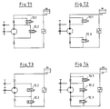
- Figures 7.1 to 7.4 show four embodiments, at which different combinations of 2/2 way valves 10.1, 10.2, 10.3 can be applied. With these four Embodiments are not just the arrangements and Circuits different, but it can also different sizes and different nominal sizes of mentioned valves 10.1 to 10.3 are used.
- Figures 8.1 to 8.4 show more Possible combinations of control chokes 20, 30 and 12. This allows different control areas to be covered.
- Figures 9.1 to 9.9 show others Possible combinations of control throttles and valves. These combinations have the advantage that the control range the single throttle to one for braking maximum necessary area can be minimized. The while change in cross-section during a switching period is by the additionally installed valve accepted. By dividing the two valves size can be saved.
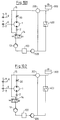
- Figures 10.1 and 10.2 each show an interesting one Embodiment of a drive system with a Retarder system.
- the drive system includes an internal combustion engine 100. This is among other things associated with a cooler 400.
- a water pump 500 is connected upstream of the engine 100, and an additional one Pump 13 is connected downstream.
- a 3/2 is very important in this embodiment
- the pump 13 on the retarder shaft 6 or on a separate shaft at the gearbox output.
- the pump 13 serves to increase the coolant throughput braking operation at high driving speed and low engine speeds. Avoiding a Torque increase occurs during the switching process here by switching the valve 14 with a time delay. This means that immediately before or during the Switching operations performed the work equipment via the bypass 15 becomes.
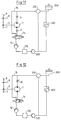
- the adjustable throttle 30 can also be a fixed throttle be replaced. This is shown in Figure 11.
- FIG. 12 is analogous to that Embodiment according to Figures 10.1 and 10.2, however Here valve 14 takes over the function of throttle 2.
- controllable throttle 30 to provide a constant throttle 3.
- FIG 13 shows a drive system in which a Retarder system integrated with a separate circuit is.
- the energy exchange through the Retarder cooler 5 made. This gives the braking energy to the coolant of the vehicle. He is in the cooling circuit of the vehicle between the engine outlet and Inlet to the thermostat 200. You can recognize the following components: a motor 100, the thermostat 200, the expansion tank 300, the vehicle radiator 400 and the coolant pump 500.
- FIG. 14.1 The diagram of a drive system shown in Figure 14.1 illustrates another way of integration of a retarder system in the cooling circuit of the vehicle.
- retarder 1 is also during the non-braking operation flowed through by coolant.
- coolant pump 500 of the vehicle is retarder 1 by the coolant pump 500 of the vehicle.
- retarder 1 analogous to the embodiment according to FIG. 1 - in the Cooling circuit switched on and also in the Drive train of a vehicle.
- retarder 1 is connected in parallel to the coolant pump 500 of the vehicle.
- Retarder 1 must be switchable on drive shaft 8 or via an overdrive on a separate retarder shaft be arranged.
- the retarder acts in Brake operation as an additional pump (so-called Water pump retarder). It is therefore self-priming and is not fed by the actual water pump.
- they are omitted also expansion tank 4 and retarder cooler 5.
- a check valve 600 may be necessary.
Landscapes
- Engineering & Computer Science (AREA)
- Transportation (AREA)
- Mechanical Engineering (AREA)
- Transmission Of Braking Force In Braking Systems (AREA)
- Braking Arrangements (AREA)
Description
- D1:
- US-A-3 650 358
- D2:
- US-A-3 720 372
- D3:
- DE-A-44 08 349
Claims (5)
- Bremsanlage, insbesondere für ein Kraftfahrzeug;1.1 mit einem schaltbaren hydrodynamischen Retarder (1), der ein Statorschaufelrad und ein Rotorschaufelrad aufweist;1.2 mit einem Leitungssystem, das das Arbeitsmittel des Retarders (1) führt, und das den Retarder (1) sowie einen Kühler (5) enthält;1.3 der Retarder (1) weist eine Einlaßdrossel (2) und/oder eine Auslaßdrossel (3) auf;1.4 es sind Maßnahmen getroffen, um das Bremsmoment des Retarders (1) während des Einschaltens unterhalb des vollen Wertes zu halten; gekennzeichnet durch die folgenden Merkmale:1.5 das Leitungssystem weist eine Bypassleitung (11) auf, die den Retarder (1) und die Einlaßdrossel (2) oder den Retarder und die Auslaßdrossel (3) umgeht.
- Bremsanlage nach Anspruch 1, dadurch gekennzeichnet, daß Maßnahmen getroffen sind, um den Durchsatz an Arbeitsmittel durch den Retarder (1) zum Zwecke des Schaltens zu verändern.
- Bremsanlage nach Anspruch 1 oder 2, dadurch gekennzeichnet, daß zwei oder mehrere Bypassleitungen vorgesehen sind.
- Bremsanlage nach einem der Ansprüche 1 bis 3, dadurch gekennzeichnet, daß die Bypassleitung regelbare Drosselventile enthält.
- Bremsanlage nach einem der Ansprüche 1 bis 4, dadurch gekennzeichnet, daß diese mit einer Antriebsanlage zusammengeschaltet ist.
Applications Claiming Priority (2)
| Application Number | Priority Date | Filing Date | Title |
|---|---|---|---|
| DE4447166 | 1994-12-30 | ||
| DE4447166A DE4447166A1 (de) | 1994-12-30 | 1994-12-30 | Bremsanlage mit einem hydrodynamischen Retarder, insbesondere für ein Kraftfahrzeug |
Publications (3)
| Publication Number | Publication Date |
|---|---|
| EP0719683A2 EP0719683A2 (de) | 1996-07-03 |
| EP0719683A3 EP0719683A3 (de) | 1997-08-13 |
| EP0719683B1 true EP0719683B1 (de) | 2000-03-22 |
Family
ID=6537460
Family Applications (1)
| Application Number | Title | Priority Date | Filing Date |
|---|---|---|---|
| EP95120514A Expired - Lifetime EP0719683B1 (de) | 1994-12-30 | 1995-12-23 | Bremsanlage mit einem hydrodynamischen Retarder, insbesondere für ein Kraftfahrzeug |
Country Status (4)
| Country | Link |
|---|---|
| US (1) | US6167993B1 (de) |
| EP (1) | EP0719683B1 (de) |
| JP (1) | JPH0924806A (de) |
| DE (2) | DE4447166A1 (de) |
Families Citing this family (31)
| Publication number | Priority date | Publication date | Assignee | Title |
|---|---|---|---|---|
| DE19603184B4 (de) * | 1996-01-30 | 2005-03-10 | Zahnradfabrik Friedrichshafen | Retarder-Kühlkreislauf |
| US6561324B2 (en) | 1996-03-08 | 2003-05-13 | Voith Turbo Gmbh & Co. Kg | Drive unit including a motor and a retarder |
| EP0794326A1 (de) * | 1996-03-08 | 1997-09-10 | Voith Turbo GmbH & Co. KG | Antriebseinheit mit einem Motor und einem Retarder |
| DE19609150A1 (de) * | 1996-03-08 | 1996-10-17 | Voith Turbo Kg | Antriebseinheit mit einem Motor und einem Retarder |
| DE19641558A1 (de) * | 1996-10-09 | 1998-04-16 | Voith Turbo Kg | Verfahren und Steuerung zur Regelung des Kühlkreislaufes eines Fahrzeuges mittels einer thermisch geregelten Wasserpumpe |
| DE19641559A1 (de) * | 1996-10-09 | 1998-04-16 | Voith Turbo Kg | Antriebseinheit mit thermisch geregelter Wasserpumpe |
| DE19831922A1 (de) * | 1998-07-16 | 2000-01-20 | Man Nutzfahrzeuge Ag | Antriebseinrichtung in einem Kraftfahrzeug |
| DE19853831C1 (de) * | 1998-11-21 | 2000-03-30 | Voith Turbo Kg | Bremsanlage mit einem hydrodynamischen Retarder, insbesondere für ein Kraftfahrzeug |
| DE19853830C1 (de) | 1998-11-21 | 2000-03-02 | Voith Turbo Kg | Bremsanlage mit einem hydrodynamischen Retarder, insbesondere für ein Kraftfahrzeug |
| DE10118856A1 (de) | 2001-04-18 | 2002-10-24 | Zahnradfabrik Friedrichshafen | Bremsanlage mit einem Retarder |
| DE10232404A1 (de) * | 2002-07-18 | 2004-01-29 | Adam Opel Ag | Strömungsbremse |
| DE10342869B4 (de) * | 2003-09-15 | 2005-07-21 | Voith Turbo Gmbh & Co. Kg | Kraftfahrzeugantrieb mit einem Wasserretarder |
| CA2557355C (en) | 2004-02-26 | 2017-04-04 | Ventech, Llc | Vehicle supplemental heating system |
| DE102004043131A1 (de) * | 2004-09-07 | 2006-03-23 | Daimlerchrysler Ag | Kühlkreislauf für ein Kraftfahrzeug und Steuerungsverfahren dafür |
| DE102004061428A1 (de) * | 2004-12-21 | 2006-06-29 | Daimlerchrysler Ag | Kühlkreislauf für ein Kraftfahrzeug und Steuerungsverfahren dafür |
| DE102005009456A1 (de) * | 2005-03-02 | 2006-09-07 | Voith Turbo Gmbh & Co. Kg | Retarder-Rotationspumpen-Baugruppe |
| US8480006B2 (en) | 2006-09-08 | 2013-07-09 | Ventech, Llc | Vehicle supplemental heating system |
| DE102006048714A1 (de) * | 2006-10-14 | 2008-04-17 | Daimler Ag | Kühlkreislauf |
| DE102007006420A1 (de) * | 2007-02-05 | 2008-08-07 | Voith Patent Gmbh | Kraftfahrzeugantriebsstrang eines Kraftfahrzeugs mit einem Druckluftsystem |
| RU2499688C2 (ru) | 2008-07-29 | 2013-11-27 | Вентек, Ллс | Дополнительная система отопления, включающая встроенный теплообменник |
| US9112717B2 (en) * | 2008-07-31 | 2015-08-18 | Broadcom Corporation | Systems and methods for providing a MoCA power management strategy |
| DE102009016816A1 (de) * | 2009-04-09 | 2010-10-14 | Voith Patent Gmbh | Verfahren zur Vermeidung von Druckspitzen in einem Arbeitsmediumkreislauf mit einer hydrodynamischen Maschine |
| DE102011010555A1 (de) * | 2011-02-07 | 2012-08-09 | Voith Patent Gmbh | Hydrodynamischer Retarder |
| US9115736B2 (en) * | 2011-12-30 | 2015-08-25 | Cnh Industrial America Llc | Work vehicle fluid heating system |
| DE102013001657A1 (de) * | 2013-01-31 | 2014-07-31 | Man Truck & Bus Ag | Kühlkreislauf für ein Kraftfahrzeug mit einem hydrodynamischen Retarder |
| DE102013213556B4 (de) * | 2013-07-11 | 2025-04-17 | Voith Patent Gmbh | Kühlsystem mit eingebundener hydrodynamischer Maschine |
| DE102013219786A1 (de) * | 2013-09-30 | 2015-04-02 | Voith Patent Gmbh | Hydrauliksystem für eine hydrodynamische Maschine |
| CN103486164B (zh) * | 2013-10-15 | 2015-07-22 | 江苏理工学院 | 发动机机油介质式液力缓速装置 |
| SE539583C2 (en) * | 2015-06-26 | 2017-10-17 | Scania Cv Ab | Hydrodynamic retarder device and method for controlling it |
| SE540577C2 (en) * | 2015-06-26 | 2018-10-02 | Scania Cv Ab | Hydrodynamic retarder device |
| US9841211B2 (en) | 2015-08-24 | 2017-12-12 | Ventech, Llc | Hydrodynamic heater |
Family Cites Families (11)
| Publication number | Priority date | Publication date | Assignee | Title |
|---|---|---|---|---|
| NL6913276A (de) | 1968-09-17 | 1970-03-19 | ||
| US3720372A (en) * | 1971-12-09 | 1973-03-13 | Gen Motors Corp | Means for rapidly heating interior of a motor vehicle |
| AT333331B (de) * | 1974-02-23 | 1976-11-10 | Voith Getriebe Kg | Hydrodynamische bremse |
| DE2855654C2 (de) * | 1978-12-22 | 1982-09-23 | Voith Getriebe Kg, 7920 Heidenheim | Hydrodynamische Bremse |
| US4262781A (en) * | 1979-07-17 | 1981-04-21 | Twin Disc, Incorporated | Hydraulic retarder for multi-speed power transmissions |
| DE3441877A1 (de) * | 1984-11-16 | 1986-05-22 | Voith-Turbo Gmbh & Co Kg, 7180 Crailsheim | Kraftuebertragungsaggregat zum antrieb einer drehzahlvariablen arbeitsmaschine |
| DE3545660C1 (de) * | 1985-12-21 | 1987-06-25 | Voith Turbo Kg | Hydrodynamischer Stroemungskreislauf mit einer Einrichtung zur Reduktion der Luftventilationsleistung |
| DE3713580C1 (en) * | 1987-04-23 | 1988-11-10 | Voith Turbo Kg | Drive system with a hydrodynamic retarder |
| JP2816489B2 (ja) * | 1990-04-27 | 1998-10-27 | 曙ブレーキ工業株式会社 | リターダ制御装置 |
| DE3943708C2 (de) * | 1989-12-11 | 1996-07-25 | Voith Turbo Kg | Hydrodynamischer Retarder |
| DE4408349C2 (de) * | 1994-03-11 | 1995-08-31 | Voith Turbo Kg | Antriebseinheit mit einem Motor und einem Retarder |
-
1994
- 1994-12-30 DE DE4447166A patent/DE4447166A1/de not_active Withdrawn
-
1995
- 1995-12-23 EP EP95120514A patent/EP0719683B1/de not_active Expired - Lifetime
- 1995-12-23 DE DE59508052T patent/DE59508052D1/de not_active Expired - Lifetime
- 1995-12-28 JP JP7344056A patent/JPH0924806A/ja active Pending
-
1996
- 1996-01-02 US US08/581,950 patent/US6167993B1/en not_active Expired - Fee Related
Also Published As
| Publication number | Publication date |
|---|---|
| EP0719683A3 (de) | 1997-08-13 |
| JPH0924806A (ja) | 1997-01-28 |
| US6167993B1 (en) | 2001-01-02 |
| DE4447166A1 (de) | 1995-06-08 |
| EP0719683A2 (de) | 1996-07-03 |
| DE59508052D1 (de) | 2000-04-27 |
Similar Documents
| Publication | Publication Date | Title |
|---|---|---|
| EP0719683A2 (de) | Bremsanlage mit einem hydrodynamischen Retarder, insbesondere für ein Kraftfahrzeug | |
| DE3713580C1 (en) | Drive system with a hydrodynamic retarder | |
| DE4408350C2 (de) | Antriebseinheit und Verfahren zum Betreiben der Antriebseinheit | |
| EP1565365B1 (de) | Antriebseinheit mit einem retarder | |
| DE4408349C2 (de) | Antriebseinheit mit einem Motor und einem Retarder | |
| DE1700160B1 (de) | Getriebe mit einer einem hydrodynamischen drehmomentwandler vorgeschalteten rutschkupplung | |
| EP0958463B1 (de) | Hydrodynamischer retarder mit axial verschiebbarem stator | |
| DE3321948A1 (de) | Antriebs- und bremsanlage fuer fahrzeuge | |
| EP0427116A1 (de) | Bremsleistungswandler | |
| WO2017050724A1 (de) | Antriebsstrang mit automatgetriebe oder automatisiertem schaltgetriebe, einer ölversorgung und einem hydrodynamischen retarder | |
| EP1702820B1 (de) | Kühlkreislauf mit einer hydrodynamischen Bremse | |
| DE102013219786A1 (de) | Hydrauliksystem für eine hydrodynamische Maschine | |
| DE10360155A1 (de) | Antriebsstrang mit Abgasnutzung und Steuerungsverfahren | |
| DE19951731A1 (de) | Retardersystem | |
| DE102007055604B3 (de) | Fahrzeugkühlkreislauf mit einem hydrodynamischen Retarder | |
| EP0885351B1 (de) | Antriebseinheit mit einem motor und einem retarder | |
| DE2235076A1 (de) | Steuereinrichtung fuer ueberbrueckungskupplungen, insbesondere fuer von einer gasturbine angetriebene getriebe | |
| DE1455685A1 (de) | Hydrodynamische Bremse | |
| DE19934621B4 (de) | Kreislaufsystem eines Retarders | |
| WO2007107314A1 (de) | Hydrodynamische baugruppe mit einem retarder und einer hydrodynamischen kupplung | |
| DE3832559C1 (de) | ||
| DE102015207851A1 (de) | Steuerungsverfahren und damit betriebener hydrodynamischer Retarder | |
| DE102013219795A1 (de) | Hydrauliksystem für eine hydrodynamische Maschine | |
| DE1700160C (de) | Getriebe mit einer einem hydrodynami sehen Drehmomentwandler vorgeschalteten Rutschkupplung | |
| DE1125300B (de) | Vorrichtung zum Abbremsen von Fahrzeugen, insbesondere Kraftfahrzeugen, mit hydrostatischem Getriebe |
Legal Events
| Date | Code | Title | Description |
|---|---|---|---|
| PUAI | Public reference made under article 153(3) epc to a published international application that has entered the european phase |
Free format text: ORIGINAL CODE: 0009012 |
|
| AK | Designated contracting states |
Kind code of ref document: A2 Designated state(s): DE FR GB IT SE |
|
| PUAL | Search report despatched |
Free format text: ORIGINAL CODE: 0009013 |
|
| AK | Designated contracting states |
Kind code of ref document: A3 Designated state(s): DE FR GB IT SE |
|
| 17P | Request for examination filed |
Effective date: 19971111 |
|
| 17Q | First examination report despatched |
Effective date: 19980428 |
|
| RAP1 | Party data changed (applicant data changed or rights of an application transferred) |
Owner name: VOITH TURBO BETEILIGUNGS GMBH |
|
| GRAG | Despatch of communication of intention to grant |
Free format text: ORIGINAL CODE: EPIDOS AGRA |
|
| GRAG | Despatch of communication of intention to grant |
Free format text: ORIGINAL CODE: EPIDOS AGRA |
|
| GRAH | Despatch of communication of intention to grant a patent |
Free format text: ORIGINAL CODE: EPIDOS IGRA |
|
| GRAH | Despatch of communication of intention to grant a patent |
Free format text: ORIGINAL CODE: EPIDOS IGRA |
|
| GRAA | (expected) grant |
Free format text: ORIGINAL CODE: 0009210 |
|
| AK | Designated contracting states |
Kind code of ref document: B1 Designated state(s): DE FR GB IT SE |
|
| PG25 | Lapsed in a contracting state [announced via postgrant information from national office to epo] |
Ref country code: SE Free format text: THE PATENT HAS BEEN ANNULLED BY A DECISION OF A NATIONAL AUTHORITY Effective date: 20000322 Ref country code: IT Free format text: LAPSE BECAUSE OF FAILURE TO SUBMIT A TRANSLATION OF THE DESCRIPTION OR TO PAY THE FEE WITHIN THE PRESCRIBED TIME-LIMIT;WARNING: LAPSES OF ITALIAN PATENTS WITH EFFECTIVE DATE BEFORE 2007 MAY HAVE OCCURRED AT ANY TIME BEFORE 2007. THE CORRECT EFFECTIVE DATE MAY BE DIFFERENT FROM THE ONE RECORDED. Effective date: 20000322 Ref country code: GB Free format text: LAPSE BECAUSE OF FAILURE TO SUBMIT A TRANSLATION OF THE DESCRIPTION OR TO PAY THE FEE WITHIN THE PRESCRIBED TIME-LIMIT Effective date: 20000322 Ref country code: FR Free format text: LAPSE BECAUSE OF FAILURE TO SUBMIT A TRANSLATION OF THE DESCRIPTION OR TO PAY THE FEE WITHIN THE PRESCRIBED TIME-LIMIT Effective date: 20000322 |
|
| REF | Corresponds to: |
Ref document number: 59508052 Country of ref document: DE Date of ref document: 20000427 |
|
| EN | Fr: translation not filed | ||
| GBV | Gb: ep patent (uk) treated as always having been void in accordance with gb section 77(7)/1977 [no translation filed] |
Effective date: 20000322 |
|
| PLBE | No opposition filed within time limit |
Free format text: ORIGINAL CODE: 0009261 |
|
| STAA | Information on the status of an ep patent application or granted ep patent |
Free format text: STATUS: NO OPPOSITION FILED WITHIN TIME LIMIT |
|
| 26N | No opposition filed | ||
| PGFP | Annual fee paid to national office [announced via postgrant information from national office to epo] |
Ref country code: DE Payment date: 20130128 Year of fee payment: 18 |
|
| REG | Reference to a national code |
Ref country code: DE Ref legal event code: R119 Ref document number: 59508052 Country of ref document: DE |
|
| REG | Reference to a national code |
Ref country code: DE Ref legal event code: R119 Ref document number: 59508052 Country of ref document: DE Effective date: 20140701 |
|
| PG25 | Lapsed in a contracting state [announced via postgrant information from national office to epo] |
Ref country code: DE Free format text: LAPSE BECAUSE OF NON-PAYMENT OF DUE FEES Effective date: 20140701 |