EP1646514B1 - Laufflächeprofil das mindestens ein eingesetztes element hat - Google Patents
Laufflächeprofil das mindestens ein eingesetztes element hat Download PDFInfo
- Publication number
- EP1646514B1 EP1646514B1 EP04736640A EP04736640A EP1646514B1 EP 1646514 B1 EP1646514 B1 EP 1646514B1 EP 04736640 A EP04736640 A EP 04736640A EP 04736640 A EP04736640 A EP 04736640A EP 1646514 B1 EP1646514 B1 EP 1646514B1
- Authority
- EP
- European Patent Office
- Prior art keywords
- tread
- contact
- relief
- inserted element
- wells
- Prior art date
- Legal status (The legal status is an assumption and is not a legal conclusion. Google has not performed a legal analysis and makes no representation as to the accuracy of the status listed.)
- Expired - Lifetime
Links
- 238000005096 rolling process Methods 0.000 claims description 9
- 230000007423 decrease Effects 0.000 claims description 2
- 238000000465 moulding Methods 0.000 description 9
- XLYOFNOQVPJJNP-UHFFFAOYSA-N water Substances O XLYOFNOQVPJJNP-UHFFFAOYSA-N 0.000 description 5
- 239000000463 material Substances 0.000 description 4
- 238000000034 method Methods 0.000 description 3
- 239000000203 mixture Substances 0.000 description 3
- 230000002787 reinforcement Effects 0.000 description 2
- 230000016571 aggressive behavior Effects 0.000 description 1
- 230000015572 biosynthetic process Effects 0.000 description 1
- 230000009194 climbing Effects 0.000 description 1
- 230000006835 compression Effects 0.000 description 1
- 238000007906 compression Methods 0.000 description 1
- 230000002349 favourable effect Effects 0.000 description 1
- 238000003780 insertion Methods 0.000 description 1
- 230000037431 insertion Effects 0.000 description 1
- 238000012986 modification Methods 0.000 description 1
- 230000004048 modification Effects 0.000 description 1
- 210000003462 vein Anatomy 0.000 description 1
- 238000004073 vulcanization Methods 0.000 description 1
Images
Classifications
-
- B—PERFORMING OPERATIONS; TRANSPORTING
- B60—VEHICLES IN GENERAL
- B60C—VEHICLE TYRES; TYRE INFLATION; TYRE CHANGING; CONNECTING VALVES TO INFLATABLE ELASTIC BODIES IN GENERAL; DEVICES OR ARRANGEMENTS RELATED TO TYRES
- B60C11/00—Tyre tread bands; Tread patterns; Anti-skid inserts
- B60C11/03—Tread patterns
- B60C11/12—Tread patterns characterised by the use of narrow slits or incisions, e.g. sipes
-
- B—PERFORMING OPERATIONS; TRANSPORTING
- B60—VEHICLES IN GENERAL
- B60C—VEHICLE TYRES; TYRE INFLATION; TYRE CHANGING; CONNECTING VALVES TO INFLATABLE ELASTIC BODIES IN GENERAL; DEVICES OR ARRANGEMENTS RELATED TO TYRES
- B60C11/00—Tyre tread bands; Tread patterns; Anti-skid inserts
- B60C11/03—Tread patterns
- B60C11/13—Tread patterns characterised by the groove cross-section, e.g. for buttressing or preventing stone-trapping
Definitions
- the present invention relates to an improvement of the treads for tires intended to equip trucks; it relates in particular to the sculpture of these treads.
- This invention is particularly, but not exclusively, intended to be implemented for radial-carcass tires intended for non-driving axles of heavy goods vehicles.
- Such tires generally comprise a carcass reinforcement surmounted radially on the outside by a crown belt, itself surmounted by a tread provided with a sculpture formed essentially of ribs of general circumferential orientation delimited by grooves of the same orientation or blocks delimited by circumferential grooves and transverse grooves or a combination of blocks and ribs.
- the document GB 903389 shows such a solution.
- the document japanese 20021234313 shows a sculpture comprising in a groove a rib intended to reduce the wear of a tread, this rib being provided with a plurality of transverse extensions intended to bear on the walls of the ribs of the sculpture.
- the subject of the invention is a tread according to claim 1.
- the average length of a bridge means the dimension of a bridge taken in a direction parallel to the track on the running surface of the lateral faces of the intercalated element and the adjacent carving element.
- the average distance between two bridges corresponds to the length of the space between two connecting bridges in the same direction on the same side face.
- the distance between two lateral faces connected by the bridges is at most equal to 2.0 mm and even more preferably to at most equal to 1.0 mm.
- the radially outer surface of the intercalated element is radially offset relative to the contact surface of the adjacent carving elements, that is to say that it only touches the ground when a load is applied to the tire provided. of this tread (that is to say when the compression of neighboring elements is sufficient).
- the shift is chosen so that this outer surface of the interposed element comes into contact with the ground in new condition or only after a short initial use compared to the total duration of use of the band before removal for wear.
- a tread comprising ribs is easily applicable to the case of a tread comprising a plurality of blocks arranged circumferentially or transversely; for example, the inserted element may equally well be a single continuous rib or a plurality of blocks arranged in the same direction.
- the connecting bridges do not create closed zones, that is to say areas with no possibility of flow other than opening on the running surface.
- the impact of this last provision is also favorable on noise during taxiing.
- known techniques of molding the incision separating the intercalated element from at least one adjacent carving element may be employed with a sheet or film material of which the thickness corresponds to the width of the incision (that is to say to the average distance between the facing faces delimiting the incision) and having the characteristic to withstand the molding and vulcanization efforts of the tread, this sheet having a plurality of orifices for passing the rubber mixture during said molding to form connecting bridges connecting the sacrificed element to at least one neighboring element.
- This sheet is preferably made of a material that can self-eliminate during rolling for example by the action of moisture on said material.
- connection ratio between an intercalated element and the neighboring elements so as to confer both a sufficient connection stiffness between said relief elements and a flexibility adapted to allow the implementation contact of the element interposed with the roadway while driving.
- Linkage rate means the ratio of the total bridging area (that is, the sum of the intersection surfaces of all bridges on a lateral face of a relief element) and the total area of bridging. the side face. When this rate is zero it means that there is no bridge, and when it is equal to the unit, it means that the connecting bridges occupy the entire lateral surface of the connected elements.
- an interposed element is connected to a neighboring element by a plurality of connecting bridges extending in the direction of the depth of the groove from depth V to the interior of which is placed said interposed element, these bridges extending between the intercalated element and the neighboring elements on at least 80% of the depth V.
- this interposed element is formed by a succession of blocks, it may be advantageous, in addition to the rubber bridge connections with the adjacent carving elements, to provide for the presence of mechanical connection bridges of rubber mixture between said interposed elements themselves.
- At least one intercalated element is connected to neighboring elements by bridges extending from the contact surface of the element inserted to the bottom of the groove at the end of the groove. inside which the intercalated element is provided.
- This variant can be obtained by customarily molding the surfaces of the carving elements and molding at the same time kinds of wells (corresponding to the spaces between the bridges) extending in the thickness of the tread. These wells may or may not be evenly spaced in the circumferential or transverse direction depending on the intercalated element considered.
- the wells then form successive parts of the same incision and the spaces filled with rubber between these wells form connecting bridges.
- each well or space, of length D in a direction parallel to the trace on the rolling surface of the lateral faces of an intercalated element and its adjacent carving element has a sectional area of between 0.5 mm 2 and 10. mm 2 .
- Wells made can take any geometry of section: in particular, circular, elliptical, rectangular, triangular, or semi circular, half elliptical, half rectangular. To avoid as much as possible a concentration of stresses at certain points of the wells in use, it is advisable to use a section geometry of the wells whose contour does not include angular points (thus a circular shape is preferred to a rectangular shape in particular). In addition, it is possible to extend the bottoms of the wells to avoid the concentrations of bottom forces of said wells.
- the wells thus produced may have, seen in a meridian section plane, that is to say containing the axis of rotation of the tire provided with a tread according to the invention, appropriate inclinations with respect to a perpendicular to the running surface.
- the angle of inclination is preferably less than or equal to 25 ° with a perpendicular to the running surface. More preferably still, the angle is between 0 ° and 15 °.
- the wells formed are not isolated from each other but that they are interconnected to allow the passage of water.
- the molding method described in the patent US 6484772 or in the patent US 6,143,223 can be implemented.
- the method of molding the incision with a sheet or film provided with orifices is adapted .
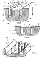
- FIG. 1 shows a partial perspective view of a tread for a tire according to the invention
- Figure 2 shows a sectional view along the line II-II of Figure 1;
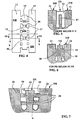
- Figure 3 shows a partial view of a mold for molding the sculpture shown in Figure 1;
- FIGS 4, 5, 6 show, in plan and in section, the same variant tread according to the invention, the intercalated elements are interconnected blocks;
- Figure 7 shows a variant in which an inserted element delimits with a neighboring element an inclined incision.
- FIG 1 there is a partial perspective view of a tread B according to the invention.
- this partial view there are two ribs 1 delimiting a groove 2 inside which is disposed an interspersed rib 3 extending in the same direction as the neighboring ribs 1.
- This interspersed rib 3 delimits with each of the neighboring ribs 1 an incision 4 with a width of 0.6 mm.
- this interspersed rib 3 is mechanically connected to the two neighboring ribs 1 by rubber connecting bridges 6.
- connecting bridges 6 extend throughout the height of the interspersed rib 3 from the contact surface 31 of said element to the bottom 42 of the incisions 4.
- FIG. 2 shows the interposed rib 3 whose contact surface 31 with the ground is offset with respect to the contact surface 10 of the neighboring ribs 1 with an appropriate offset f for contacting the contact face 31 of the rib interposed 3 with the roadway when driving. This contact is made either from the use of the tire provided with this new tread, or after initial use.
- the bridges 6 have a length L and a width d and are separated from each other by wells 41 whose section is rectangular with a length D and a width d.
- an intermediate rib 3' forming a relief on the surface of the mold with an offset f, this intermediate rib 3 'having a height less than the height of the neighboring ribs 2', said heights being measured by relative to the surface of the mold.
- a plurality of rods 4' of rectangular section are arranged, regularly distributed, a plurality of rods 4' of rectangular section.
- rods 41 'of rectangular section but is of course not limited to this geometry and in particular other sectional shapes can be used as circular, elliptical, triangular shapes.
- the connecting bridges can be formed only from a height equivalent to a certain percentage of the depth of the incision under the contact surface of the interposed carving element as is the case with the variant shown in FIGS. 4 to 6.
- FIG. 4 shows a plan view of the tread surface of a tread according to the invention comprising at least two ribs 11 and between these ribs a series of intercalated blocks 13; each of said blocks 13 having an outer surface 131 slightly offset below the contact surface 110 of the ribs 11 flanking said blocks 13.
- Each of these blocks 13 is connected on its two lateral faces to the two ribs 11 by connecting bridges 16 which can be seen in Figure 6 (section along the line VI-VI) they themselves are radially offset to the The bridges 16 extend in the direction of the depth only over part of the depth of the incision separating the interposed blocks from the adjacent carving elements in such a way that the bridges 16 extend in the direction of the depth. maintain satisfactory performance in water drainage when driving on wet roads.
- intercalated blocks 13 are interconnected by connecting bridges 17 visible on the section along the line VV shown in Figure 5.
- connecting bridges 17 visible on the section along the line VV shown in Figure 5.
- only the grooves most sensitive to breaks in the groove bottom are provided with intercalated relief elements and the other grooves are left without inserted element to allow sufficient drainage and thus maintain necessary performance especially on wet pavement.
- an interposed relief element is connected by a plurality of two-rib gum bridges.
- an interposed element 23 is disposed between two adjacent elements 21 and has a contact surface 231 offset by an amount f relative to the external surface 210 of the neighboring elements 21.
- This interposed element 23 defines with each neighboring element a incision 25 inclined at an average angle ⁇ with a perpendicular to the contact surface 231 of the intercalated element.
- angle ⁇ is 10 ° and such that the width of the interposed element seen from the running surface of the strip decreases with the wear of said strip.
- the interposed element 23 is connected to each neighboring element 21 by connecting bridges 26 offset in the direction of the depth of the inclined incision 25.
- the average angle ⁇ of inclination of the incisions between an intercalated element and a neighboring element with a perpendicular to the contact surface of the intercalated element is at most equal to 25 °.
- the angle of inclination of the incisions can be chosen so that the width of the inserted element increases with wear. It is also possible to combine the presence of an incision inclined at an angle greater than zero and another incision forming a zero angle with a perpendicular to the running surface.
- this invention may be combined with the presence axially outside the ribs edges of a so-called sacrificed rib with respect to wear in order to protect this edge rib from uneven wear on its edges.
- This sacrificial rib has an external contact surface intended to come into contact with the rolling road, the difference of the rolling radii of this sacrificed rib and the rib edge leads to amplify the sliding on the rib sacrificed thus causing a pronounced wear on this rib.
- This rib offset in the direction of the thickness is separated from the rib edge by a narrow incision whose walls vis-à-vis are connected by a plurality of connecting bridges rubber mixture.
- the bridges are formed in grooves of generally circumferential (longitudinal) orientation and delimit closed spaces (with the exception of the opening on the running surface), it may be advantageous to be able to strip the web with a plurality of channels opening on one side outside the band and on the other side in the spaces.
Landscapes
- Engineering & Computer Science (AREA)
- Mechanical Engineering (AREA)
- Tires In General (AREA)
- Road Paving Structures (AREA)
- Fats And Perfumes (AREA)
- Medicines Containing Material From Animals Or Micro-Organisms (AREA)
Claims (8)
- Lauffläche (B) aus einer Kautschukmischung für einen Luftreifen, wobei diese Lauffläche mit einem Profil versehen ist, das aus einer Vielzahl von Reliefelementen (1, 11, 21) ausgebildet ist, welche Kontaktflächen (10, 110, 210) umfassen, um während des Fahrens mit der Fahrbahn in Kontakt zu kommen, wobei jedes Reliefelement Seitenflächen umfasst, welche die Nuten (4) oder Einschnitte begrenzen, wobei diese Lauffläche (B) außerdem mindestens ein eingesetztes Element (3, 13, 23) umfasst, das in einer Nut (4) zwischen zwei benachbarten Reliefelementen (1, 11, 21) angeordnet ist, wobei dieses eingesetzte Element Seitenflächen und eine Kontaktfläche (31, 131, 231) aufweist, wobei die Kontaktfläche radial zum Inneren der Lauffläche im Verhältnis zu den Kontaktflächen (10, 110, 220) der benachbarten Elemente dergestalt versetzt ist, dass es beim Fahren mit der Fahrbahn in Kontakt sein kann, wobei dieses eingesetzte Element über zwei seiner Seitenflächen mit benachbarten Reliefelementen (1, 11, 21) über eine Vielzahl von Verbindungsstegen (6, 16, 26) aus einer Kautschukmischung mit einer Länge L verbunden ist, wobei die Verbindungsstege mit dem eingesetzten Element und jedem benachbarten Reliefelement eine Vielzahl von Senken (41) mittlerer Länge D begrenzen, wobei die Länge D und der mittlere Abstand L in eine parallele Richtung zu der Spur auf der Laufoberfläche der Seitenflächen eines eingesetzten Elementes (3) und des benachbarten Profilelementes (1) gemessen werden, wobei die Lauffläche dadurch gekennzeichnet ist, dass die mittlere Länge L der Verbindungsstege zwischen der einfachen und sechsfachen mittleren Länge D der Senken liegt.
- Lauffläche nach Anspruch 1, dadurch gekennzeichnet, dass die ausgebildeten Senken eine Tiefe V aufweisen, wobei sich die Verbindungsstege (6, 16, 26) in die Richtung der Tiefe über mindestens 80% der Tiefe V erstrecken.
- Lauffläche nach Anspruch 1 oder Anspruch 2, dadurch gekennzeichnet, dass die Senken (41), in Verlängerung auf der Laufoberfläche, eine mittlere Querschnittsfläche aufweisen, die zwischen 0,5 und 10 mm2 beträgt.
- Lauffläche nach Anspruch 3, dadurch gekennzeichnet, dass jede Senke oder jeder Einschnitt im Verhältnis zu einer Senkrechten auf der Laufoberfläche in einem Winkel von weniger oder gleich 25° geneigt ist.
- Lauffläche nach Anspruch 4, dadurch gekennzeichnet, dass der Neigungswinkel der Senken dergestalt ist, dass sich die Kontaktoberfläche des eingesetzten Elementes mit der Abnutzung verändert.
- Lauffläche nach Anspruch 5, dadurch gekennzeichnet, dass die Kontaktoberfläche des eingesetzten Elementes mit der Fahrbahn im Verlauf der Abnutzung abnimmt.
- Lauffläche nach einem der Ansprüche 1 bis 6,
dadurch gekennzeichnet, dass die Spur auf der Laufoberfläche der Seitenflächen eines eingesetzten Elementes (3) und des benachbarten Reliefelementes (1) in einer allgemeinen Längsausrichtung liegt. - Lauffläche nach Anspruch 7, dadurch gekennzeichnet, dass mindestens ein eingesetztes Element aus einer durchgehenden Rippe besteht.
Applications Claiming Priority (2)
| Application Number | Priority Date | Filing Date | Title |
|---|---|---|---|
| FR0307233 | 2003-06-16 | ||
| PCT/EP2004/006333 WO2004110791A1 (fr) | 2003-06-16 | 2004-06-11 | Sculpture de bande de roulement ayant au moins un element intercale |
Publications (2)
| Publication Number | Publication Date |
|---|---|
| EP1646514A1 EP1646514A1 (de) | 2006-04-19 |
| EP1646514B1 true EP1646514B1 (de) | 2007-09-26 |
Family
ID=33548124
Family Applications (1)
| Application Number | Title | Priority Date | Filing Date |
|---|---|---|---|
| EP04736640A Expired - Lifetime EP1646514B1 (de) | 2003-06-16 | 2004-06-11 | Laufflächeprofil das mindestens ein eingesetztes element hat |
Country Status (7)
| Country | Link |
|---|---|
| US (1) | US7380577B2 (de) |
| EP (1) | EP1646514B1 (de) |
| JP (1) | JP4685770B2 (de) |
| CN (1) | CN1805859A (de) |
| AT (1) | ATE374120T1 (de) |
| DE (1) | DE602004009186T2 (de) |
| WO (1) | WO2004110791A1 (de) |
Families Citing this family (19)
| Publication number | Priority date | Publication date | Assignee | Title |
|---|---|---|---|---|
| ATE450384T1 (de) * | 2003-06-16 | 2009-12-15 | Michelin Soc Tech | Schutzrippe für eine reifenlauffläche |
| CN1805857A (zh) * | 2003-06-16 | 2006-07-19 | 米其林技术公司 | 包括有通风的保护性胎纹的轮胎胎面 |
| US7252728B2 (en) * | 2004-07-12 | 2007-08-07 | The Goodyear Tire & Rubber Company | Method for forming a pneumatic tire |
| US7249620B2 (en) * | 2004-07-12 | 2007-07-31 | The Goodyear Tire & Rubber Company | Pneumatic tire |
| US7468153B2 (en) * | 2004-12-30 | 2008-12-23 | The Goodyear Tire & Rubber Co. | Degradable blading for tire curing molds |
| FR2890600B1 (fr) * | 2005-09-15 | 2010-02-26 | Michelin Soc Tech | Dispositif anti-usure irreguliere pour bande de roulement de pneumatique |
| JP4943797B2 (ja) * | 2006-10-02 | 2012-05-30 | 東洋ゴム工業株式会社 | 空気入りタイヤ及びタイヤ成形型 |
| US7980281B2 (en) * | 2006-10-02 | 2011-07-19 | Toyo Tire & Rubber Co., Ltd. | Pneumatic tire with tread having protruding stripe in groove bottom and tire mold for making the tire |
| FR2937902B1 (fr) * | 2008-11-06 | 2011-12-09 | Michelin Rech Tech | Pneumatique muni de temoins d'usure sonores |
| FR2954220B1 (fr) * | 2009-12-17 | 2012-03-23 | Michelin Soc Tech | Pneu a faible resistance au roulement. |
| FR2959960B1 (fr) * | 2010-05-11 | 2014-05-16 | Michelin Soc Tech | Procede de realisation d'une bande de roulement pour un pneumatique de vehicule |
| FR2995823A1 (fr) * | 2012-09-26 | 2014-03-28 | Michelin & Cie | Dispositif perfectionne anti bruit de resonance pour pneu |
| EP2914445B1 (de) * | 2012-10-30 | 2018-12-05 | Pirelli Tyre S.p.A. | Verfahren zur erhöhung der leistung eines reifens für schwerlastenfahrzeugräder und reifen für schwerlastenfahrzeugräder |
| CA2927941C (en) | 2013-10-30 | 2020-06-02 | Bridgestone Americas Tire Operations, Llc | Snow tire with directional paddles |
| FR3013635B1 (fr) * | 2013-11-26 | 2015-12-11 | Michelin & Cie | Bande de roulement a drainage ameliore pour pneu |
| CN106029402A (zh) | 2013-12-26 | 2016-10-12 | 普利司通美国轮胎运营有限责任公司 | 具有挠性闸门装置的轮胎胎面 |
| DE102014210823A1 (de) * | 2014-06-06 | 2015-12-17 | Continental Reifen Deutschland Gmbh | Fahrzeugluftreifen |
| JP6763706B2 (ja) * | 2016-06-30 | 2020-09-30 | Toyo Tire株式会社 | 空気入りタイヤ |
| CN110001299A (zh) * | 2019-05-07 | 2019-07-12 | 江苏通用科技股份有限公司 | 轮胎胎面的分段式加强筋结构 |
Family Cites Families (17)
| Publication number | Priority date | Publication date | Assignee | Title |
|---|---|---|---|---|
| GB903389A (en) | 1957-09-30 | 1962-08-15 | Pirelli | Improvements in or relating to pneumatic tyres |
| GB1274554A (en) * | 1968-06-27 | 1972-05-17 | Dunlop Holdings Ltd | Improvements in or relating to tyres |
| JP2700808B2 (ja) * | 1988-09-27 | 1998-01-21 | 株式会社ブリヂストン | 空気入りタイヤ |
| JPH02179506A (ja) * | 1988-12-29 | 1990-07-12 | Bridgestone Corp | 空気入りタイヤ |
| US5115850A (en) * | 1991-02-19 | 1992-05-26 | The Goodyear Tire & Rubber Company | Tread with improved groove design |
| CA2261237A1 (en) * | 1996-07-22 | 1998-01-29 | The Goodyear Tire & Rubber Company | A tire tread having flow-through grooves |
| JP3150622B2 (ja) * | 1996-09-03 | 2001-03-26 | 住友ゴム工業株式会社 | 空気入りタイヤ |
| FR2759323B1 (fr) | 1997-02-12 | 1999-03-19 | Michelin & Cie | Sculpture de bande de roulement et procede de fabrication |
| JP4127881B2 (ja) * | 1997-08-20 | 2008-07-30 | 東洋ゴム工業株式会社 | 空気入りタイヤ |
| FR2772663A1 (fr) | 1997-12-24 | 1999-06-25 | Michelin & Cie | Procede et element moulant pour mouler une decoupure dans une bande de roulement de pneumatique |
| JP2001030715A (ja) * | 1999-07-16 | 2001-02-06 | Ohtsu Tire & Rubber Co Ltd :The | 空気入りタイヤ |
| JP2001030716A (ja) * | 1999-07-19 | 2001-02-06 | Bridgestone Corp | 重荷重用空気入りラジアルタイヤ |
| WO2001039994A1 (en) * | 1999-11-30 | 2001-06-07 | Pirelli Pneumatici S.P.A. | Tyre for vehicle wheels, particularly for medium and heavy motor vehicles such as lorries and similar |
| JP3493177B2 (ja) * | 2000-12-19 | 2004-02-03 | 住友ゴム工業株式会社 | 空気入りタイヤ |
| JP2002234313A (ja) | 2001-02-08 | 2002-08-20 | Bridgestone Corp | 空気入りタイヤ |
| CN1805857A (zh) * | 2003-06-16 | 2006-07-19 | 米其林技术公司 | 包括有通风的保护性胎纹的轮胎胎面 |
| ATE450384T1 (de) * | 2003-06-16 | 2009-12-15 | Michelin Soc Tech | Schutzrippe für eine reifenlauffläche |
-
2004
- 2004-06-11 EP EP04736640A patent/EP1646514B1/de not_active Expired - Lifetime
- 2004-06-11 DE DE602004009186T patent/DE602004009186T2/de not_active Expired - Lifetime
- 2004-06-11 CN CN200480016786.0A patent/CN1805859A/zh active Pending
- 2004-06-11 AT AT04736640T patent/ATE374120T1/de not_active IP Right Cessation
- 2004-06-11 JP JP2006515906A patent/JP4685770B2/ja not_active Expired - Fee Related
- 2004-06-11 WO PCT/EP2004/006333 patent/WO2004110791A1/fr active IP Right Grant
-
2005
- 2005-12-14 US US11/302,879 patent/US7380577B2/en not_active Expired - Lifetime
Non-Patent Citations (1)
| Title |
|---|
| None * |
Also Published As
| Publication number | Publication date |
|---|---|
| JP2006527685A (ja) | 2006-12-07 |
| CN1805859A (zh) | 2006-07-19 |
| US20060090829A1 (en) | 2006-05-04 |
| DE602004009186D1 (de) | 2007-11-08 |
| DE602004009186T2 (de) | 2008-06-26 |
| US7380577B2 (en) | 2008-06-03 |
| EP1646514A1 (de) | 2006-04-19 |
| ATE374120T1 (de) | 2007-10-15 |
| JP4685770B2 (ja) | 2011-05-18 |
| WO2004110791A1 (fr) | 2004-12-23 |
Similar Documents
| Publication | Publication Date | Title |
|---|---|---|
| EP1646514B1 (de) | Laufflächeprofil das mindestens ein eingesetztes element hat | |
| EP2834089B1 (de) | Reifenlauffläche für eine durch ein schwerlastfahrzeug getriebene achse | |
| EP2694302B1 (de) | Lauffläche mit mindestens einer wellenförmigen nut und herstellungsverfahren dafür | |
| EP2099621B1 (de) | Doppelausrichtungseinschnitte umfassende lauffläche | |
| CA2383301C (fr) | Bande de roulement comportant des nervures pourvues d'incisions d'inclinaison variable | |
| EP2525988B1 (de) | Reifenlauffläche mit verbesserter geräuschsreduktionsvorrichtung | |
| EP2731811B1 (de) | Reifen mit lauffläche beinhaltend einschnitte mit breiten und dünnen abschnitten | |
| EP3648991B1 (de) | Reifen dessen lauffläche wellenförmige nuten aufweist | |
| WO2007101794A1 (fr) | Incision de bande de roulement comprenant des parties de blocage | |
| EP3802154B1 (de) | Reifenlauffläche mit gewellten rillen und lamellen | |
| EP3439898A1 (de) | Reifenlauffläche | |
| WO2018096257A1 (fr) | Bande de roulement comportant des nervures incisées | |
| EP1638785B1 (de) | Schutzrippe für eine reifenlauffläche | |
| FR3099414A1 (fr) | Bande de roulement de pneumatique pour véhicule poids lourd | |
| CA2320876C (fr) | Armature de sommet pour pneumatique | |
| EP3439897B1 (de) | Reifenlauffläche | |
| WO2017174927A1 (fr) | Bande de roulement améliorée pour pneu | |
| EP3898281B1 (de) | Lauffläche mit durch versetzte öffnungen erweiterten verborgenen hohlräumen | |
| WO2017174928A1 (fr) | Bande de roulement pour pneu | |
| EP3074244B1 (de) | Reifenlauffläche | |
| WO2024115261A1 (fr) | Pneumatique pour vehicule poids lourd avec une bande de roulement a robustesse amelioree | |
| EP4232303A1 (de) | Schwerlastfahrzeugreifenlauffläche mit verbesserter robustheit | |
| WO2017093662A1 (fr) | Géométrie de blocs d'une bande de roulement pour pneu |
Legal Events
| Date | Code | Title | Description |
|---|---|---|---|
| PUAI | Public reference made under article 153(3) epc to a published international application that has entered the european phase |
Free format text: ORIGINAL CODE: 0009012 |
|
| 17P | Request for examination filed |
Effective date: 20060116 |
|
| AK | Designated contracting states |
Kind code of ref document: A1 Designated state(s): AT BE BG CH CY CZ DE DK EE ES FI FR GB GR HU IE IT LI LU MC NL PL PT RO SE SI SK TR |
|
| DAX | Request for extension of the european patent (deleted) | ||
| GRAP | Despatch of communication of intention to grant a patent |
Free format text: ORIGINAL CODE: EPIDOSNIGR1 |
|
| GRAS | Grant fee paid |
Free format text: ORIGINAL CODE: EPIDOSNIGR3 |
|
| GRAA | (expected) grant |
Free format text: ORIGINAL CODE: 0009210 |
|
| AK | Designated contracting states |
Kind code of ref document: B1 Designated state(s): AT BE BG CH CY CZ DE DK EE ES FI FR GB GR HU IE IT LI LU MC NL PL PT RO SE SI SK TR |
|
| REG | Reference to a national code |
Ref country code: GB Ref legal event code: FG4D Free format text: NOT ENGLISH |
|
| REG | Reference to a national code |
Ref country code: CH Ref legal event code: EP |
|
| REF | Corresponds to: |
Ref document number: 602004009186 Country of ref document: DE Date of ref document: 20071108 Kind code of ref document: P |
|
| REG | Reference to a national code |
Ref country code: IE Ref legal event code: FG4D Free format text: LANGUAGE OF EP DOCUMENT: FRENCH |
|
| GBT | Gb: translation of ep patent filed (gb section 77(6)(a)/1977) |
Effective date: 20071219 |
|
| PG25 | Lapsed in a contracting state [announced via postgrant information from national office to epo] |
Ref country code: FI Free format text: LAPSE BECAUSE OF FAILURE TO SUBMIT A TRANSLATION OF THE DESCRIPTION OR TO PAY THE FEE WITHIN THE PRESCRIBED TIME-LIMIT Effective date: 20070926 |
|
| PG25 | Lapsed in a contracting state [announced via postgrant information from national office to epo] |
Ref country code: AT Free format text: LAPSE BECAUSE OF FAILURE TO SUBMIT A TRANSLATION OF THE DESCRIPTION OR TO PAY THE FEE WITHIN THE PRESCRIBED TIME-LIMIT Effective date: 20070926 Ref country code: PL Free format text: LAPSE BECAUSE OF FAILURE TO SUBMIT A TRANSLATION OF THE DESCRIPTION OR TO PAY THE FEE WITHIN THE PRESCRIBED TIME-LIMIT Effective date: 20070926 |
|
| NLV1 | Nl: lapsed or annulled due to failure to fulfill the requirements of art. 29p and 29m of the patents act | ||
| PG25 | Lapsed in a contracting state [announced via postgrant information from national office to epo] |
Ref country code: ES Free format text: LAPSE BECAUSE OF FAILURE TO SUBMIT A TRANSLATION OF THE DESCRIPTION OR TO PAY THE FEE WITHIN THE PRESCRIBED TIME-LIMIT Effective date: 20080106 Ref country code: GR Free format text: LAPSE BECAUSE OF FAILURE TO SUBMIT A TRANSLATION OF THE DESCRIPTION OR TO PAY THE FEE WITHIN THE PRESCRIBED TIME-LIMIT Effective date: 20071227 Ref country code: NL Free format text: LAPSE BECAUSE OF FAILURE TO SUBMIT A TRANSLATION OF THE DESCRIPTION OR TO PAY THE FEE WITHIN THE PRESCRIBED TIME-LIMIT Effective date: 20070926 |
|
| REG | Reference to a national code |
Ref country code: IE Ref legal event code: FD4D |
|
| PG25 | Lapsed in a contracting state [announced via postgrant information from national office to epo] |
Ref country code: PT Free format text: LAPSE BECAUSE OF FAILURE TO SUBMIT A TRANSLATION OF THE DESCRIPTION OR TO PAY THE FEE WITHIN THE PRESCRIBED TIME-LIMIT Effective date: 20080226 Ref country code: SK Free format text: LAPSE BECAUSE OF FAILURE TO SUBMIT A TRANSLATION OF THE DESCRIPTION OR TO PAY THE FEE WITHIN THE PRESCRIBED TIME-LIMIT Effective date: 20070926 Ref country code: CZ Free format text: LAPSE BECAUSE OF FAILURE TO SUBMIT A TRANSLATION OF THE DESCRIPTION OR TO PAY THE FEE WITHIN THE PRESCRIBED TIME-LIMIT Effective date: 20070926 |
|
| PG25 | Lapsed in a contracting state [announced via postgrant information from national office to epo] |
Ref country code: SE Free format text: LAPSE BECAUSE OF FAILURE TO SUBMIT A TRANSLATION OF THE DESCRIPTION OR TO PAY THE FEE WITHIN THE PRESCRIBED TIME-LIMIT Effective date: 20071226 Ref country code: RO Free format text: LAPSE BECAUSE OF FAILURE TO SUBMIT A TRANSLATION OF THE DESCRIPTION OR TO PAY THE FEE WITHIN THE PRESCRIBED TIME-LIMIT Effective date: 20070926 |
|
| PG25 | Lapsed in a contracting state [announced via postgrant information from national office to epo] |
Ref country code: DK Free format text: LAPSE BECAUSE OF FAILURE TO SUBMIT A TRANSLATION OF THE DESCRIPTION OR TO PAY THE FEE WITHIN THE PRESCRIBED TIME-LIMIT Effective date: 20070926 |
|
| PLBE | No opposition filed within time limit |
Free format text: ORIGINAL CODE: 0009261 |
|
| STAA | Information on the status of an ep patent application or granted ep patent |
Free format text: STATUS: NO OPPOSITION FILED WITHIN TIME LIMIT |
|
| 26N | No opposition filed |
Effective date: 20080627 |
|
| PG25 | Lapsed in a contracting state [announced via postgrant information from national office to epo] |
Ref country code: IE Free format text: LAPSE BECAUSE OF FAILURE TO SUBMIT A TRANSLATION OF THE DESCRIPTION OR TO PAY THE FEE WITHIN THE PRESCRIBED TIME-LIMIT Effective date: 20070926 |
|
| BERE | Be: lapsed |
Owner name: SOC. DE TECHNOLOGIE MICHELIN Effective date: 20080630 |
|
| PG25 | Lapsed in a contracting state [announced via postgrant information from national office to epo] |
Ref country code: MC Free format text: LAPSE BECAUSE OF NON-PAYMENT OF DUE FEES Effective date: 20080630 |
|
| REG | Reference to a national code |
Ref country code: CH Ref legal event code: PL |
|
| PG25 | Lapsed in a contracting state [announced via postgrant information from national office to epo] |
Ref country code: BE Free format text: LAPSE BECAUSE OF NON-PAYMENT OF DUE FEES Effective date: 20080630 |
|
| PG25 | Lapsed in a contracting state [announced via postgrant information from national office to epo] |
Ref country code: EE Free format text: LAPSE BECAUSE OF FAILURE TO SUBMIT A TRANSLATION OF THE DESCRIPTION OR TO PAY THE FEE WITHIN THE PRESCRIBED TIME-LIMIT Effective date: 20070926 |
|
| PG25 | Lapsed in a contracting state [announced via postgrant information from national office to epo] |
Ref country code: SI Free format text: LAPSE BECAUSE OF FAILURE TO SUBMIT A TRANSLATION OF THE DESCRIPTION OR TO PAY THE FEE WITHIN THE PRESCRIBED TIME-LIMIT Effective date: 20070926 Ref country code: LI Free format text: LAPSE BECAUSE OF NON-PAYMENT OF DUE FEES Effective date: 20080630 Ref country code: CH Free format text: LAPSE BECAUSE OF NON-PAYMENT OF DUE FEES Effective date: 20080630 |
|
| PG25 | Lapsed in a contracting state [announced via postgrant information from national office to epo] |
Ref country code: CY Free format text: LAPSE BECAUSE OF FAILURE TO SUBMIT A TRANSLATION OF THE DESCRIPTION OR TO PAY THE FEE WITHIN THE PRESCRIBED TIME-LIMIT Effective date: 20070926 |
|
| PG25 | Lapsed in a contracting state [announced via postgrant information from national office to epo] |
Ref country code: BG Free format text: LAPSE BECAUSE OF FAILURE TO SUBMIT A TRANSLATION OF THE DESCRIPTION OR TO PAY THE FEE WITHIN THE PRESCRIBED TIME-LIMIT Effective date: 20071226 |
|
| PG25 | Lapsed in a contracting state [announced via postgrant information from national office to epo] |
Ref country code: HU Free format text: LAPSE BECAUSE OF FAILURE TO SUBMIT A TRANSLATION OF THE DESCRIPTION OR TO PAY THE FEE WITHIN THE PRESCRIBED TIME-LIMIT Effective date: 20080327 Ref country code: LU Free format text: LAPSE BECAUSE OF NON-PAYMENT OF DUE FEES Effective date: 20080611 |
|
| PG25 | Lapsed in a contracting state [announced via postgrant information from national office to epo] |
Ref country code: TR Free format text: LAPSE BECAUSE OF FAILURE TO SUBMIT A TRANSLATION OF THE DESCRIPTION OR TO PAY THE FEE WITHIN THE PRESCRIBED TIME-LIMIT Effective date: 20070926 |
|
| PGFP | Annual fee paid to national office [announced via postgrant information from national office to epo] |
Ref country code: GB Payment date: 20100618 Year of fee payment: 7 |
|
| GBPC | Gb: european patent ceased through non-payment of renewal fee |
Effective date: 20110611 |
|
| PG25 | Lapsed in a contracting state [announced via postgrant information from national office to epo] |
Ref country code: GB Free format text: LAPSE BECAUSE OF NON-PAYMENT OF DUE FEES Effective date: 20110611 |
|
| PGFP | Annual fee paid to national office [announced via postgrant information from national office to epo] |
Ref country code: IT Payment date: 20140624 Year of fee payment: 11 |
|
| PG25 | Lapsed in a contracting state [announced via postgrant information from national office to epo] |
Ref country code: IT Free format text: LAPSE BECAUSE OF NON-PAYMENT OF DUE FEES Effective date: 20150611 |
|
| REG | Reference to a national code |
Ref country code: FR Ref legal event code: PLFP Year of fee payment: 13 |
|
| REG | Reference to a national code |
Ref country code: FR Ref legal event code: PLFP Year of fee payment: 14 |
|
| REG | Reference to a national code |
Ref country code: FR Ref legal event code: PLFP Year of fee payment: 15 |
|
| PGFP | Annual fee paid to national office [announced via postgrant information from national office to epo] |
Ref country code: DE Payment date: 20210618 Year of fee payment: 18 Ref country code: FR Payment date: 20210622 Year of fee payment: 18 |
|
| REG | Reference to a national code |
Ref country code: DE Ref legal event code: R119 Ref document number: 602004009186 Country of ref document: DE |
|
| PG25 | Lapsed in a contracting state [announced via postgrant information from national office to epo] |
Ref country code: FR Free format text: LAPSE BECAUSE OF NON-PAYMENT OF DUE FEES Effective date: 20220630 |
|
| PG25 | Lapsed in a contracting state [announced via postgrant information from national office to epo] |
Ref country code: DE Free format text: LAPSE BECAUSE OF NON-PAYMENT OF DUE FEES Effective date: 20230103 |