EP3898281B1 - Lauffläche mit durch versetzte öffnungen erweiterten verborgenen hohlräumen - Google Patents
Lauffläche mit durch versetzte öffnungen erweiterten verborgenen hohlräumen Download PDFInfo
- Publication number
- EP3898281B1 EP3898281B1 EP19842816.1A EP19842816A EP3898281B1 EP 3898281 B1 EP3898281 B1 EP 3898281B1 EP 19842816 A EP19842816 A EP 19842816A EP 3898281 B1 EP3898281 B1 EP 3898281B1
- Authority
- EP
- European Patent Office
- Prior art keywords
- tread
- hidden channel
- extensions
- openings
- channel
- Prior art date
- Legal status (The legal status is an assumption and is not a legal conclusion. Google has not performed a legal analysis and makes no representation as to the accuracy of the status listed.)
- Active
Links
- 230000000295 complement effect Effects 0.000 claims description 5
- 238000004891 communication Methods 0.000 claims description 4
- 238000005096 rolling process Methods 0.000 description 36
- XLYOFNOQVPJJNP-UHFFFAOYSA-N water Substances O XLYOFNOQVPJJNP-UHFFFAOYSA-N 0.000 description 9
- 239000000463 material Substances 0.000 description 5
- 230000009467 reduction Effects 0.000 description 4
- 230000002349 favourable effect Effects 0.000 description 3
- 238000004519 manufacturing process Methods 0.000 description 3
- 230000008030 elimination Effects 0.000 description 1
- 238000003379 elimination reaction Methods 0.000 description 1
- 238000005265 energy consumption Methods 0.000 description 1
- 238000010348 incorporation Methods 0.000 description 1
- 230000001788 irregular Effects 0.000 description 1
- 239000007788 liquid Substances 0.000 description 1
- 238000012986 modification Methods 0.000 description 1
- 230000004048 modification Effects 0.000 description 1
- 238000000465 moulding Methods 0.000 description 1
- 230000000750 progressive effect Effects 0.000 description 1
- 230000000007 visual effect Effects 0.000 description 1
Images


Classifications
-
- B—PERFORMING OPERATIONS; TRANSPORTING
- B60—VEHICLES IN GENERAL
- B60C—VEHICLE TYRES; TYRE INFLATION; TYRE CHANGING; CONNECTING VALVES TO INFLATABLE ELASTIC BODIES IN GENERAL; DEVICES OR ARRANGEMENTS RELATED TO TYRES
- B60C11/00—Tyre tread bands; Tread patterns; Anti-skid inserts
- B60C11/03—Tread patterns
- B60C11/032—Patterns comprising isolated recesses
- B60C11/0323—Patterns comprising isolated recesses tread comprising channels under the tread surface, e.g. for draining water
-
- B—PERFORMING OPERATIONS; TRANSPORTING
- B60—VEHICLES IN GENERAL
- B60C—VEHICLE TYRES; TYRE INFLATION; TYRE CHANGING; CONNECTING VALVES TO INFLATABLE ELASTIC BODIES IN GENERAL; DEVICES OR ARRANGEMENTS RELATED TO TYRES
- B60C11/00—Tyre tread bands; Tread patterns; Anti-skid inserts
- B60C11/03—Tread patterns
- B60C11/12—Tread patterns characterised by the use of narrow slits or incisions, e.g. sipes
- B60C11/1272—Width of the sipe
- B60C11/1281—Width of the sipe different within the same sipe, i.e. enlarged width portion at sipe bottom or along its length
-
- B—PERFORMING OPERATIONS; TRANSPORTING
- B60—VEHICLES IN GENERAL
- B60C—VEHICLE TYRES; TYRE INFLATION; TYRE CHANGING; CONNECTING VALVES TO INFLATABLE ELASTIC BODIES IN GENERAL; DEVICES OR ARRANGEMENTS RELATED TO TYRES
- B60C11/00—Tyre tread bands; Tread patterns; Anti-skid inserts
- B60C11/03—Tread patterns
- B60C11/13—Tread patterns characterised by the groove cross-section, e.g. for buttressing or preventing stone-trapping
- B60C11/1307—Tread patterns characterised by the groove cross-section, e.g. for buttressing or preventing stone-trapping with special features of the groove walls
- B60C11/1315—Tread patterns characterised by the groove cross-section, e.g. for buttressing or preventing stone-trapping with special features of the groove walls having variable inclination angles, e.g. warped groove walls
-
- B—PERFORMING OPERATIONS; TRANSPORTING
- B60—VEHICLES IN GENERAL
- B60C—VEHICLE TYRES; TYRE INFLATION; TYRE CHANGING; CONNECTING VALVES TO INFLATABLE ELASTIC BODIES IN GENERAL; DEVICES OR ARRANGEMENTS RELATED TO TYRES
- B60C2200/00—Tyres specially adapted for particular applications
- B60C2200/06—Tyres specially adapted for particular applications for heavy duty vehicles
Definitions
- the invention relates to treads for heavy goods vehicle tires and more particularly to the hollow arrangements with which these strips are provided, for which driving performance in rainy weather is made more durable.
- cutout any cavity or hollow made in particular by molding in a tire tread, this cutout extending both in the depth of the tread and in a main direction - which is the direction of flow water in the cutout when driving in rainy weather.
- open groove is meant an open cutout on a rolling surface of a tread coming into contact with the roadway, this groove being delimited by facing walls, the average distance between these walls being appropriate for that these walls are not in contact with each other under normal conditions of use of the tire.
- incision is meant a thin cutout having a small average width, this average width corresponding to the average distance separating the opposite walls delimiting it, and such that, under normal conditions of use of the tire, these walls can come, at least partially, into contact with one another when passing through the region of contact with the roadway.
- hidden cavity or channel is meant a cavity formed under the new rolling surface of the tread, this cavity being intended to form a new open groove on the new rolling surface generated after predetermined partial wear.
- a hidden cavity is delimited by two side walls facing each other, these two side walls being connected together by a lower part forming a bottom and by an upper part in the extension of these walls radially outwards. In this upper part, an incision can open to connect the hidden cavity to the new rolling surface.
- a hidden cavity can take any geometric shape such as: circular, rectangular, triangular.
- the main direction of a hidden channel is defined as the direction in which the water flows when driving on a road surface covered with water.
- thickness of material to be used in a tread we mean the thickness of material of this tread that can be worn out while driving before reaching a legal limit of use, this limit being able to be identified by indicator devices. wear formed particularly in the grooves. When this limit is reached, intervention is necessary in order to either reform a new hollow pattern on the tire tread or to put on a new tread or even change the tire.
- radial or radially are used to indicate a direction which, when taken on the tire, is a direction perpendicular to the axis of rotation of the tire while, when taken on a strip rolling alone, it corresponds to the direction of the thickness of said strip.
- circumferential to indicate a direction which corresponds to a direction tangent to any circle centered on the axis of rotation of the tire.
- This circumferential direction corresponds to the longitudinal direction of the tread, the latter being formed in the manner of a flat strip before its incorporation in the manufacture of a new tire or its retreading.
- transverse refers to a direction that is parallel to the direction of the tire's axis of rotation. This direction is perpendicular to the radial direction and the circumferential direction. A direction is said to be oblique when it forms an angle greater than zero with the circumferential or longitudinal direction.
- the tread of this tire must offer water drainage performance on the road which is always above a minimum performance known as safety performance. Consequently and taking into account the progressive wear of the tread which progressively reduces the cross-sectional areas of the grooves and consequently the capacity of these grooves to evacuate a given quantity of liquid, it is usual to produce grooves opening onto the running surface in new condition and extending into the thickness of the strip up to at least a level which corresponds to a legal wear limit requiring removal of the strip.
- WO 2018/158546 A1 describes a tread of a tire intended to equip a heavy goods vehicle trailer, not being suitable for conferring a preferential direction of rotation.
- WO 2020/204942 A1 published after the effective date of the present application, describes a tread comprising first openings of extensions oriented, such that the part of each first opening furthest from the incision enters last, and not first , in contact with the roadway, depending on the direction of rotation of the tire.
- the present invention relates to a solution to this problem of increasing the length of oblique or transverse edges while maintaining a good level of overall rigidity of a tire tread provided with hidden cavities.
- the subject of the invention is a tread for a heavy goods vehicle tire according to claim 1.
- each extension extending a hidden channel opens on the one hand on or near the rolling surface, according to a first opening, and on the other hand in the hidden channel, according to a second opening, constituting a secondary channel, having a significant section.
- an extension within the meaning of the invention, is not an incision.
- each first opening of an extension opening on or near the rolling surface, has an elongated shape, characterized by a maximum dimension L0 and a minimum dimension I0 corresponding respectively to the length and width of the smallest rectangle in which said first opening is inscribed.
- a first opening typically has a minimum dimension I0 at least equal to 3 mm and a maximum dimension L0 at least equal to 10 mm and at most equal to 100 mm.
- the orientation of the maximum dimension L0 is generally transverse or oblique, to obtain the largest possible transverse or oblique edge length, which guarantees an optimal contribution of the first opening to the longitudinal adhesion.
- the first opening of an extension can be transversely positioned either in contact with the incision extending the hidden canal, or at a distance from said incision.
- the first opening of an extension can open onto the new tread surface allowing water to drain from the start of use of the tire.
- this first opening can be offset a short distance towards the inside of the tread and only appear on the tread surface after a predetermined partial wear of the tread, thus offering the possibility of have greater rigidity when new.
- each extension is generally extended towards the rolling surface by an incision of small width, this incision being connected to the incision extending the hidden channel.
- the first openings of the extensions are offset transversely with respect to the incision extending the hidden channel, a complementary incision of small width connecting each extension to the rolling surface, this complementary incision being further connected to the incision extending the hidden canal. It should be noted that the first opening of an extension has a smaller dimension or width significantly greater than the width of the complementary incision.
- all the first openings of the extensions of the same hidden channel are formed on the same side with respect to the incision extending said channel towards the rolling surface.
- each extension opens at least partially onto one of the side walls delimiting a hidden channel, this making it possible to maintain the presence of transverse or oblique edges even after the appearance of additional grooves during the opening of hidden channels after wear.
- all the extensions of the same hidden channel have their first openings located between the incision extending a hidden channel towards the rolling surface and one of the external edges of the tread in order to allow drainage of this edge.
- the first openings of the extensions of the same hidden channel are formed on the same side relative to the incision extending the hidden channel and moreover they are transversely offset from each other.
- the first openings of the extensions are oriented to make an angle A of between 20 degrees and 70 degrees with the main direction of the hidden channel to which these extensions are connected.
- the tread is suitable for conferring a preferential direction of rotation to the tire provided with this strip.
- This preferential direction is generally materialized on the tread or on the tire by a visual element or marking such as an arrow.
- the first openings of the extensions putting a hidden channel into communication with the outside are advantageously all oriented to promote the flow of water present on a roadway towards the inside of the tread. Precisely, these first openings are oriented so that the part of each first opening furthest from the incision extending the hidden channel first enters into contact with the roadway.
- the first openings of the extensions have elongated geometries on the rolling surface, that is to say whose ratio between the dimension I0 and the maximum dimension L0 is between 1/2 and 1/15.
- the maximum dimension of the first openings is at least equal to 10 mm and at most equal to 100 mm, and their minimum dimension I0 is at least equal to 3 mm
- the tread comprises at least one hidden channel having a plurality of extensions, this hidden channel extending in the longitudinal direction of the tread (this direction corresponds to the circumferential direction when the tread equips a tire).
- the invention also relates to a tire for a heavy goods vehicle, this tire being equipped with a tread as described above.
- a tread 1 for a heavy goods vehicle tire comprises a rolling surface 10 and, open on this rolling surface, cutouts including at least one incision 21 oriented longitudinally (circumferentially on the tire provided with this strip). .
- This longitudinal incision 21 opens at its other end into a hidden channel 22 oriented longitudinally.
- This hidden channel 22 is entirely formed inside the tread and is intended to form, after a predetermined partial wear, a new groove open on the rolling surface. It is thus possible to adjust, by limiting it, the volume of hollows in the new tread in order to better manage the reduction in rigidity linked to the presence of these hollows.
- the longitudinal incision 21 has a width adapted to be able to close when passing through contact with a roadway, that is to say that the walls delimiting said incision can at least partly come into contact with each other. other and thus isolate channel 22 from the outside.
- the hidden channel 22 is delimited by facing walls 221, 222, these walls being connected both in their lower part forming the bottom 223 of the channel 22 and in their upper part 224 (close to the rolling surface 10). It is in this upper part 224 of channel 22 that incision 21 opens.
- a plurality of extensions 3 are further formed comprising a first opening 30 opening onto the rolling surface 10 when new.
- These extensions 3 include a second opening 32 opening in the incision 21 and in the upper part 224 of the hidden channel 22.
- Each extension 3 extends entirely on the same side with respect to the incision 21; the extensions 3 are arranged alternately on each side of the incision 21.
- the first opening 30 of each extension 3 on the rolling surface at nine has a rectangular geometry of length Lo and width Io, the length Lo being oriented transversely on the tread. These widths Io and length Lo are in the example described in a ratio of 1 to 5.
- the extensions 3 thus allow the new drainage of the rolling surface towards the hidden channel 22 and their offset relative to the longitudinal incision 21 surmounting the hidden channel 22 generates transversely oriented edges favorable for obtaining traction and braking performance . Furthermore, the contour of these first openings 30 on the rolling surface changes with the wear of the tread, which is favorable for preventing the appearance of irregular wear. In this variant, the first opening 30 of each extension 3 has a surface which gradually reduces with wear.
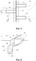
- FIG. 3 shows a second variant which is not according to the invention according to which the first openings 30 of the extensions 3 opening onto a hidden channel 22 are all positioned on the same side in relation to the incision 21 surmounting the hidden channel 22
- the first openings 30 are positioned nine and transversely at different distances H1, H2 relative to the incision 21 surmounting the hidden channel 22.
- FIG 4 shows a cross section of the tread of this second variant.
- the extension 3 comprises a second opening 32 opening in one of the side walls delimiting the hidden channel 22. Thanks to this arrangement, it is possible to maintain a length of transverse edges even after the hidden channel has become an additional groove.
- FIG 5 shows a variant according to the invention of arrangement of the first openings 30 of the extensions 3 opening into a hidden channel 22 oriented longitudinally in a tread.
- the tread is designed to impose a direction of rotation on the tire (marked in the figure by an arrow R).
- This preferred direction of rotation is generally identified on the tire by a specific visible sign.
- the case described shows first openings 30 of oblong shape, the largest of whose dimensions denoted Lo makes an angle A with the longitudinal direction followed by the hidden channel 22 and the incision 21 extending it to the rolling surface.
- the additional incisions 31 formed between the longitudinal incision 21 and each extension 3 are oriented with the same angle A.
- this angle A is such that during rolling, it is the part 301 of the first opening 30 of each extension 3 furthest from the longitudinal incision 21 which first enters into contact with the roadway. This arrangement further improves drainage between the roadway and the interior of the hidden canal.
Landscapes
- Engineering & Computer Science (AREA)
- Mechanical Engineering (AREA)
- Tires In General (AREA)
Claims (10)
- Laufstreifen (1) für einen Lkw-Reifen mit einer Lauffläche (10) im Neuzustand, die dazu bestimmt ist, beim Rollen eines mit diesem Laufstreifen versehenen Reifens mit einer Fahrbahn in Kontakt zu gelangen, wobei dieser Laufstreifen (1) umfasst:- mindestens einen Hohlraum, der einen verborgenen Kanal (22) bildet, der dazu bestimmt ist, nach einem vorbestimmten teilweisen Verschleiß eine zusätzliche Rille zu bilden, wobei dieser verborgene Kanal (22) durch zwei einander gegenüberliegende Seitenwände (221,222) begrenzt wird, wobei diese beiden Seitenwände untereinander durch einen unteren Teil, der einen Boden (223) bildet, und durch einen oberen Teil (224) verbunden sind,- wobei jeder verborgene Kanal (22) zu der Lauffläche (10) hin im Neuzustand und über seine gesamte Länge durch eine Lamelle (21) von geringer Breite verlängert wird, die sich in dem oberen Teil (224) des Kanals öffnet;- wobei mindestens ein verborgener Kanal (22) eine Mehrzahl von Erweiterungen (3) hat, die sich von diesem verborgenen Kanal aus zu der Lauffläche hin erstrecken, um den verborgenen Kanal (22) und die Außenseite des Laufstreifens zumindest ab einem teilweisen Verschleiß des Streifens in Verbindung zu bringen,- wobei jede Erweiterung (3) ein Nebenkanal mit zwei Öffnungen ist, einer ersten Öffnung (30) auf oder nahe der Lauffläche (10) von länglicher Form mit dem kleinsten Maß 10 und dem größten Maßdem mit diesem Streifen versehenen Reifen eine bevorzugte Drehrichtung zu verleihen, dass bei mindestens einem mit Erweiterungen (3) versehenen verborgenen Kanal (22) jede erste Öffnung (30) dieser Erweiterungen (3) vollständig auf einer Seite der den verborgenen Kanal (22) verlängernden Lamelle (21) gebildet ist und dass die ersten Öffnungen (30) der Erweiterungen (3), die einen verborgenen Kanal (22) mit der Außenseite in Verbindung bringen, alle ausgerichtet sind, damit der Teil (301) jeder ersten Öffnung (30), der am weitesten von der den verborgenen Kanal verlängernden Lamelle (21) entfernt ist, als Erster in Kontakt mit der Fahrbahn gelangt.
- Laufstreifen (1) nach Anspruch 1, bei dem alle ersten Öffnungen (30) der Erweiterungen (3) eines selben verborgenen Kanals (22) auf einer selben Seite in Bezug auf die den Kanal zu der Lauffläche (10) hin verlängernde Lamelle (21) gebildet sind.
- Laufstreifen (1) nach Anspruch 1 oder Anspruch 2, bei dem die ersten Öffnungen (30) in Bezug auf die den verborgenen Kanal (22) verlängernde Lamelle (21) quer versetzt sind, wobei eine ergänzende Lamelle (21) von geringer Breite jede Erweiterung (3) mit der Lauffläche verbindet, wobei diese ergänzende Lamelle (31) ferner mit der den verborgenen Kanal (22) verlängernden Lamelle (21) verbunden ist.
- Laufstreifen (1) nach einem der Ansprüche 1 bis 3, bei dem sich die zweite Öffnung (32) jeder Erweiterung (3) mindestens zum Teil an einer der einen verborgenen Kanal (22) begrenzenden Seitenwände (221, 222) öffnet.
- Laufstreifen (1) nach Anspruch 3 oder Anspruch 4, bei dem die ersten Öffnungen (30) der Erweiterungen (3) eines selben verborgenen Kanals (22) auf einer selben Seite in Bezug auf die den verborgenen Kanal verlängernde Lamelle (21) gebildet sind und darüber hinaus zueinander quer versetzt sind.
- Laufstreifen (1) nach einem der Ansprüche 1 bis 5, bei dem die ersten Öffnungen (30) der Erweiterungen (3) ausgerichtet sind, um einen Winkel A zwischen 20 Grad und 70 Grad mit der Hauptrichtung des verbogenen Kanals (22) zu bilden, mit dem diese Erweiterungen (3) verbunden sind.
- Laufstreifen (1) nach einem der Ansprüche 1 bis 6, bei dem die ersten Öffnungen (30) der Erweiterungen (3) Geometrien auf der Lauffläche haben, die länglich sind, das heißt, deren Verhältnis zwischen dem kleinsten Maß 10 und dem größten Maß L0 zwischen 1/2 und 1/15 beträgt.
- Laufstreifen (1) nach einem der Ansprüche 1 bis 7, bei dem sich die ersten Öffnungen (30) der Erweiterungen (3) auf der Lauffläche des Streifens erst nach einem teilweisen Verschleiß dieses Streifens öffnen.
- Laufstreifen (1) nach einem der Ansprüche 1 bis 8, bei dem sich mindestens ein verborgener Kanal (22), der eine Mehrzahl von Erweiterungen (3) hat, in der Längsrichtung des Laufstreifens erstreckt.
- Lkw-Reifen, der mit einem Laufstreifen nach einem der Ansprüche 1 bis 9 versehen ist.
Applications Claiming Priority (3)
| Application Number | Priority Date | Filing Date | Title |
|---|---|---|---|
| FR1873050A FR3089866A3 (fr) | 2018-12-17 | 2018-12-17 | Bande de roulement ayant des cavités cachées prolongées par des ouvertures décalées |
| FR1900893A FR3089863B1 (fr) | 2018-12-17 | 2019-01-31 | Bande de roulement ayant des cavités cachées prolongées par des ouvertures décalées |
| PCT/FR2019/053082 WO2020128271A1 (fr) | 2018-12-17 | 2019-12-16 | Bande de roulement ayant des cavites cachees prolongees par des ouvertures decalees |
Publications (2)
| Publication Number | Publication Date |
|---|---|
| EP3898281A1 EP3898281A1 (de) | 2021-10-27 |
| EP3898281B1 true EP3898281B1 (de) | 2024-02-07 |
Family
ID=66867444
Family Applications (1)
| Application Number | Title | Priority Date | Filing Date |
|---|---|---|---|
| EP19842816.1A Active EP3898281B1 (de) | 2018-12-17 | 2019-12-16 | Lauffläche mit durch versetzte öffnungen erweiterten verborgenen hohlräumen |
Country Status (4)
| Country | Link |
|---|---|
| EP (1) | EP3898281B1 (de) |
| CN (1) | CN113242803B (de) |
| FR (2) | FR3089866A3 (de) |
| WO (1) | WO2020128271A1 (de) |
Families Citing this family (1)
| Publication number | Priority date | Publication date | Assignee | Title |
|---|---|---|---|---|
| DE102021205792A1 (de) * | 2021-06-08 | 2022-12-08 | Continental Reifen Deutschland Gmbh | Fahrzeugluftreifen |
Citations (1)
| Publication number | Priority date | Publication date | Assignee | Title |
|---|---|---|---|---|
| WO2020204942A1 (en) * | 2019-04-05 | 2020-10-08 | Compagnie Generale Des Etablissements Michelin | Truck tire with circumferential sipe having blind micro sipes |
Family Cites Families (18)
| Publication number | Priority date | Publication date | Assignee | Title |
|---|---|---|---|---|
| GB1407790A (en) * | 1971-09-15 | 1975-09-24 | Dunlop Ltd | Tyres |
| JPH05155202A (ja) * | 1991-12-09 | 1993-06-22 | Bridgestone Corp | タイヤ用プレキュアトレッド及びその製造方法ならびにこれを用いた更生タイヤ |
| JP3397450B2 (ja) * | 1994-06-24 | 2003-04-14 | 株式会社ブリヂストン | 空気入りタイヤ |
| JP5032852B2 (ja) * | 2007-01-09 | 2012-09-26 | 東洋ゴム工業株式会社 | 空気入りタイヤ及びタイヤ成型用金型 |
| JP2008168872A (ja) * | 2007-01-15 | 2008-07-24 | Toyo Tire & Rubber Co Ltd | 空気入りタイヤ及びタイヤ成型用金型 |
| JP5064869B2 (ja) * | 2007-04-12 | 2012-10-31 | 株式会社ブリヂストン | 空気入りタイヤ |
| EP2323858B1 (de) | 2008-09-11 | 2013-03-20 | Michelin Recherche et Technique S.A. | Reifenlauffläche mit variabler oberfläche |
| FR2940185B1 (fr) * | 2008-12-22 | 2010-12-17 | Michelin Soc Tech | Bande de roulement a volume de drainage ameliore |
| FR2959448B1 (fr) * | 2010-04-30 | 2012-10-26 | Michelin Soc Tech | Bande de roulement de pneu pour vehicule poids lourd de type remorque |
| FR2983779A1 (fr) * | 2011-12-09 | 2013-06-14 | Michelin Soc Tech | Combinaison d'une structure de pneu poids lourd avec une sculpture de bande de roulement |
| JP5827655B2 (ja) * | 2013-09-25 | 2015-12-02 | 住友ゴム工業株式会社 | 空気入りタイヤ |
| FR3017076B1 (fr) * | 2014-02-03 | 2016-02-12 | Michelin & Cie | Bande de roulement pour pneu poids lourd |
| FR3018222B1 (fr) * | 2014-03-10 | 2017-09-01 | Michelin & Cie | Bande de roulement comportant une texture a fort contraste dans une rainure |
| WO2016190881A1 (en) * | 2015-05-28 | 2016-12-01 | Compagnie Generale Des Etablissements Michelin | Truck tire tread and truck tire |
| WO2017039679A1 (en) * | 2015-09-04 | 2017-03-09 | Compagnie Generale Des Etablissements Michelin | Truck tire tread and truck tire |
| WO2017176280A1 (en) * | 2016-04-08 | 2017-10-12 | Compagnie Generale Des Etablissements Michelin | Truck tire tread and truck tire |
| FR3061081A1 (fr) * | 2016-12-28 | 2018-06-29 | Compagnie Generale Des Etablissements Michelin | Bande de roulement comportant des cavites cachees |
| FR3063454A1 (fr) * | 2017-03-03 | 2018-09-07 | Compagnie Generale Des Etablissements Michelin | Bande de roulement de pneu pour vehicule remorque poids lourd |
-
2018
- 2018-12-17 FR FR1873050A patent/FR3089866A3/fr active Pending
-
2019
- 2019-01-31 FR FR1900893A patent/FR3089863B1/fr active Active
- 2019-12-16 CN CN201980082994.7A patent/CN113242803B/zh active Active
- 2019-12-16 EP EP19842816.1A patent/EP3898281B1/de active Active
- 2019-12-16 WO PCT/FR2019/053082 patent/WO2020128271A1/fr unknown
Patent Citations (1)
| Publication number | Priority date | Publication date | Assignee | Title |
|---|---|---|---|---|
| WO2020204942A1 (en) * | 2019-04-05 | 2020-10-08 | Compagnie Generale Des Etablissements Michelin | Truck tire with circumferential sipe having blind micro sipes |
Also Published As
| Publication number | Publication date |
|---|---|
| CN113242803B (zh) | 2023-01-31 |
| CN113242803A (zh) | 2021-08-10 |
| FR3089866A3 (fr) | 2020-06-19 |
| FR3089863A1 (fr) | 2020-06-19 |
| FR3089863B1 (fr) | 2023-04-28 |
| WO2020128271A1 (fr) | 2020-06-25 |
| US20220055413A1 (en) | 2022-02-24 |
| EP3898281A1 (de) | 2021-10-27 |
Similar Documents
| Publication | Publication Date | Title |
|---|---|---|
| EP2834089B1 (de) | Reifenlauffläche für eine durch ein schwerlastfahrzeug getriebene achse | |
| EP2588327B1 (de) | Reifenprofil mit verringertem rollgeräusch | |
| EP3094502B1 (de) | Erweiterbare reifenlauffläche | |
| EP3648991B1 (de) | Reifen dessen lauffläche wellenförmige nuten aufweist | |
| EP2788204B1 (de) | Kombination von einer schwerlastreifenstruktur mit einem laufstreifenprofil | |
| EP3439898B1 (de) | Reifenlauffläche | |
| EP3727893B1 (de) | Reifenlauffläche mit wellenförmigen rillen | |
| EP3802154B1 (de) | Reifenlauffläche mit gewellten rillen und lamellen | |
| WO2012152593A1 (fr) | Bande de roulement combinant inserts et incisions | |
| EP3853044B1 (de) | Reifenlauffläche mit feineinschnitten und komplexen rillen | |
| WO2016188956A1 (fr) | Pneu pour poids lourd avec dispositif indicateur d'usure | |
| WO2018096257A1 (fr) | Bande de roulement comportant des nervures incisées | |
| EP3562689A1 (de) | Lauffläche für einen schwerlastfahrzeugreifen | |
| EP3703958B1 (de) | Lauffläche für einen schwerlastfahrzeugreifen | |
| EP3898280B1 (de) | Lauffläche mit unterbrochenen rillen | |
| EP3898281B1 (de) | Lauffläche mit durch versetzte öffnungen erweiterten verborgenen hohlräumen | |
| WO2010063750A1 (fr) | Bande de roulement comportant des incisions et des cavites | |
| EP3898279B1 (de) | Lauffläche mit verborgenen vertiefungen und nuten | |
| WO2020128235A1 (fr) | Bande de roulement comportant des cavites cachees et des rainures | |
| FR3090485A1 (fr) | Bande de roulement de pneu pour poids lourd ayant des incisions améliorées. | |
| WO2020128237A1 (fr) | Bande de roulement comportant des rainures interrompues | |
| EP3383673B1 (de) | Reifenlaufflächenblockgeometrie | |
| FR3044594A1 (fr) | Bande de roulement pour pneu hivernal poids lourd. |
Legal Events
| Date | Code | Title | Description |
|---|---|---|---|
| STAA | Information on the status of an ep patent application or granted ep patent |
Free format text: STATUS: UNKNOWN |
|
| STAA | Information on the status of an ep patent application or granted ep patent |
Free format text: STATUS: THE INTERNATIONAL PUBLICATION HAS BEEN MADE |
|
| PUAI | Public reference made under article 153(3) epc to a published international application that has entered the european phase |
Free format text: ORIGINAL CODE: 0009012 |
|
| STAA | Information on the status of an ep patent application or granted ep patent |
Free format text: STATUS: REQUEST FOR EXAMINATION WAS MADE |
|
| 17P | Request for examination filed |
Effective date: 20210719 |
|
| AK | Designated contracting states |
Kind code of ref document: A1 Designated state(s): AL AT BE BG CH CY CZ DE DK EE ES FI FR GB GR HR HU IE IS IT LI LT LU LV MC MK MT NL NO PL PT RO RS SE SI SK SM TR |
|
| DAV | Request for validation of the european patent (deleted) | ||
| DAX | Request for extension of the european patent (deleted) | ||
| STAA | Information on the status of an ep patent application or granted ep patent |
Free format text: STATUS: EXAMINATION IS IN PROGRESS |
|
| 17Q | First examination report despatched |
Effective date: 20220927 |
|
| GRAP | Despatch of communication of intention to grant a patent |
Free format text: ORIGINAL CODE: EPIDOSNIGR1 |
|
| STAA | Information on the status of an ep patent application or granted ep patent |
Free format text: STATUS: GRANT OF PATENT IS INTENDED |
|
| INTG | Intention to grant announced |
Effective date: 20230922 |
|
| GRAS | Grant fee paid |
Free format text: ORIGINAL CODE: EPIDOSNIGR3 |
|
| GRAA | (expected) grant |
Free format text: ORIGINAL CODE: 0009210 |
|
| STAA | Information on the status of an ep patent application or granted ep patent |
Free format text: STATUS: THE PATENT HAS BEEN GRANTED |
|
| AK | Designated contracting states |
Kind code of ref document: B1 Designated state(s): AL AT BE BG CH CY CZ DE DK EE ES FI FR GB GR HR HU IE IS IT LI LT LU LV MC MK MT NL NO PL PT RO RS SE SI SK SM TR |
|
| REG | Reference to a national code |
Ref country code: GB Ref legal event code: FG4D Free format text: NOT ENGLISH |
|
| REG | Reference to a national code |
Ref country code: CH Ref legal event code: EP |
|
| REG | Reference to a national code |
Ref country code: IE Ref legal event code: FG4D Free format text: LANGUAGE OF EP DOCUMENT: FRENCH |
|
| REG | Reference to a national code |
Ref country code: DE Ref legal event code: R096 Ref document number: 602019046290 Country of ref document: DE |
|
| REG | Reference to a national code |
Ref country code: LT Ref legal event code: MG9D |
|
| REG | Reference to a national code |
Ref country code: NL Ref legal event code: MP Effective date: 20240207 |
|
| PG25 | Lapsed in a contracting state [announced via postgrant information from national office to epo] |
Ref country code: IS Free format text: LAPSE BECAUSE OF FAILURE TO SUBMIT A TRANSLATION OF THE DESCRIPTION OR TO PAY THE FEE WITHIN THE PRESCRIBED TIME-LIMIT Effective date: 20240607 |
|
| PG25 | Lapsed in a contracting state [announced via postgrant information from national office to epo] |
Ref country code: LT Free format text: LAPSE BECAUSE OF FAILURE TO SUBMIT A TRANSLATION OF THE DESCRIPTION OR TO PAY THE FEE WITHIN THE PRESCRIBED TIME-LIMIT Effective date: 20240207 |
|
| PG25 | Lapsed in a contracting state [announced via postgrant information from national office to epo] |
Ref country code: GR Free format text: LAPSE BECAUSE OF FAILURE TO SUBMIT A TRANSLATION OF THE DESCRIPTION OR TO PAY THE FEE WITHIN THE PRESCRIBED TIME-LIMIT Effective date: 20240508 |
|
| REG | Reference to a national code |
Ref country code: AT Ref legal event code: MK05 Ref document number: 1655154 Country of ref document: AT Kind code of ref document: T Effective date: 20240207 |
|
| PG25 | Lapsed in a contracting state [announced via postgrant information from national office to epo] |
Ref country code: HR Free format text: LAPSE BECAUSE OF FAILURE TO SUBMIT A TRANSLATION OF THE DESCRIPTION OR TO PAY THE FEE WITHIN THE PRESCRIBED TIME-LIMIT Effective date: 20240207 Ref country code: NL Free format text: LAPSE BECAUSE OF FAILURE TO SUBMIT A TRANSLATION OF THE DESCRIPTION OR TO PAY THE FEE WITHIN THE PRESCRIBED TIME-LIMIT Effective date: 20240207 Ref country code: RS Free format text: LAPSE BECAUSE OF FAILURE TO SUBMIT A TRANSLATION OF THE DESCRIPTION OR TO PAY THE FEE WITHIN THE PRESCRIBED TIME-LIMIT Effective date: 20240507 |
|
| PG25 | Lapsed in a contracting state [announced via postgrant information from national office to epo] |
Ref country code: ES Free format text: LAPSE BECAUSE OF FAILURE TO SUBMIT A TRANSLATION OF THE DESCRIPTION OR TO PAY THE FEE WITHIN THE PRESCRIBED TIME-LIMIT Effective date: 20240207 |
|
| PG25 | Lapsed in a contracting state [announced via postgrant information from national office to epo] |
Ref country code: AT Free format text: LAPSE BECAUSE OF FAILURE TO SUBMIT A TRANSLATION OF THE DESCRIPTION OR TO PAY THE FEE WITHIN THE PRESCRIBED TIME-LIMIT Effective date: 20240207 |
|
| PG25 | Lapsed in a contracting state [announced via postgrant information from national office to epo] |
Ref country code: RS Free format text: LAPSE BECAUSE OF FAILURE TO SUBMIT A TRANSLATION OF THE DESCRIPTION OR TO PAY THE FEE WITHIN THE PRESCRIBED TIME-LIMIT Effective date: 20240507 Ref country code: NO Free format text: LAPSE BECAUSE OF FAILURE TO SUBMIT A TRANSLATION OF THE DESCRIPTION OR TO PAY THE FEE WITHIN THE PRESCRIBED TIME-LIMIT Effective date: 20240507 Ref country code: NL Free format text: LAPSE BECAUSE OF FAILURE TO SUBMIT A TRANSLATION OF THE DESCRIPTION OR TO PAY THE FEE WITHIN THE PRESCRIBED TIME-LIMIT Effective date: 20240207 Ref country code: LT Free format text: LAPSE BECAUSE OF FAILURE TO SUBMIT A TRANSLATION OF THE DESCRIPTION OR TO PAY THE FEE WITHIN THE PRESCRIBED TIME-LIMIT Effective date: 20240207 Ref country code: IS Free format text: LAPSE BECAUSE OF FAILURE TO SUBMIT A TRANSLATION OF THE DESCRIPTION OR TO PAY THE FEE WITHIN THE PRESCRIBED TIME-LIMIT Effective date: 20240607 Ref country code: HR Free format text: LAPSE BECAUSE OF FAILURE TO SUBMIT A TRANSLATION OF THE DESCRIPTION OR TO PAY THE FEE WITHIN THE PRESCRIBED TIME-LIMIT Effective date: 20240207 Ref country code: GR Free format text: LAPSE BECAUSE OF FAILURE TO SUBMIT A TRANSLATION OF THE DESCRIPTION OR TO PAY THE FEE WITHIN THE PRESCRIBED TIME-LIMIT Effective date: 20240508 Ref country code: FI Free format text: LAPSE BECAUSE OF FAILURE TO SUBMIT A TRANSLATION OF THE DESCRIPTION OR TO PAY THE FEE WITHIN THE PRESCRIBED TIME-LIMIT Effective date: 20240207 Ref country code: ES Free format text: LAPSE BECAUSE OF FAILURE TO SUBMIT A TRANSLATION OF THE DESCRIPTION OR TO PAY THE FEE WITHIN THE PRESCRIBED TIME-LIMIT Effective date: 20240207 Ref country code: BG Free format text: LAPSE BECAUSE OF FAILURE TO SUBMIT A TRANSLATION OF THE DESCRIPTION OR TO PAY THE FEE WITHIN THE PRESCRIBED TIME-LIMIT Effective date: 20240207 Ref country code: AT Free format text: LAPSE BECAUSE OF FAILURE TO SUBMIT A TRANSLATION OF THE DESCRIPTION OR TO PAY THE FEE WITHIN THE PRESCRIBED TIME-LIMIT Effective date: 20240207 |
|
| PG25 | Lapsed in a contracting state [announced via postgrant information from national office to epo] |
Ref country code: PT Free format text: LAPSE BECAUSE OF FAILURE TO SUBMIT A TRANSLATION OF THE DESCRIPTION OR TO PAY THE FEE WITHIN THE PRESCRIBED TIME-LIMIT Effective date: 20240607 Ref country code: PL Free format text: LAPSE BECAUSE OF FAILURE TO SUBMIT A TRANSLATION OF THE DESCRIPTION OR TO PAY THE FEE WITHIN THE PRESCRIBED TIME-LIMIT Effective date: 20240207 |
|
| PG25 | Lapsed in a contracting state [announced via postgrant information from national office to epo] |
Ref country code: SE Free format text: LAPSE BECAUSE OF FAILURE TO SUBMIT A TRANSLATION OF THE DESCRIPTION OR TO PAY THE FEE WITHIN THE PRESCRIBED TIME-LIMIT Effective date: 20240207 Ref country code: PT Free format text: LAPSE BECAUSE OF FAILURE TO SUBMIT A TRANSLATION OF THE DESCRIPTION OR TO PAY THE FEE WITHIN THE PRESCRIBED TIME-LIMIT Effective date: 20240607 Ref country code: PL Free format text: LAPSE BECAUSE OF FAILURE TO SUBMIT A TRANSLATION OF THE DESCRIPTION OR TO PAY THE FEE WITHIN THE PRESCRIBED TIME-LIMIT Effective date: 20240207 Ref country code: LV Free format text: LAPSE BECAUSE OF FAILURE TO SUBMIT A TRANSLATION OF THE DESCRIPTION OR TO PAY THE FEE WITHIN THE PRESCRIBED TIME-LIMIT Effective date: 20240207 |
|
| PG25 | Lapsed in a contracting state [announced via postgrant information from national office to epo] |
Ref country code: DK Free format text: LAPSE BECAUSE OF FAILURE TO SUBMIT A TRANSLATION OF THE DESCRIPTION OR TO PAY THE FEE WITHIN THE PRESCRIBED TIME-LIMIT Effective date: 20240207 |
|
| PG25 | Lapsed in a contracting state [announced via postgrant information from national office to epo] |
Ref country code: SM Free format text: LAPSE BECAUSE OF FAILURE TO SUBMIT A TRANSLATION OF THE DESCRIPTION OR TO PAY THE FEE WITHIN THE PRESCRIBED TIME-LIMIT Effective date: 20240207 |