EP1643525A1 - Einstellmodul für eine Überstromauslösung eines Schutzschalters - Google Patents
Einstellmodul für eine Überstromauslösung eines Schutzschalters Download PDFInfo
- Publication number
- EP1643525A1 EP1643525A1 EP04405612A EP04405612A EP1643525A1 EP 1643525 A1 EP1643525 A1 EP 1643525A1 EP 04405612 A EP04405612 A EP 04405612A EP 04405612 A EP04405612 A EP 04405612A EP 1643525 A1 EP1643525 A1 EP 1643525A1
- Authority
- EP
- European Patent Office
- Prior art keywords
- lever
- circuit breaker
- module
- module according
- kompensationsbimetallfeder
- Prior art date
- Legal status (The legal status is an assumption and is not a legal conclusion. Google has not performed a legal analysis and makes no representation as to the accuracy of the status listed.)
- Granted
Links
- 230000008878 coupling Effects 0.000 claims description 9
- 238000010168 coupling process Methods 0.000 claims description 9
- 238000005859 coupling reaction Methods 0.000 claims description 9
- 238000009434 installation Methods 0.000 claims description 3
- 230000005540 biological transmission Effects 0.000 description 7
- 238000004519 manufacturing process Methods 0.000 description 3
- 238000005452 bending Methods 0.000 description 2
- 238000010276 construction Methods 0.000 description 2
- 239000002184 metal Substances 0.000 description 2
- 238000010791 quenching Methods 0.000 description 2
- 230000000171 quenching effect Effects 0.000 description 2
- 239000006096 absorbing agent Substances 0.000 description 1
- 230000015572 biosynthetic process Effects 0.000 description 1
- 230000007423 decrease Effects 0.000 description 1
- 230000001419 dependent effect Effects 0.000 description 1
- 238000001514 detection method Methods 0.000 description 1
- 238000006073 displacement reaction Methods 0.000 description 1
- 230000000694 effects Effects 0.000 description 1
- 238000010438 heat treatment Methods 0.000 description 1
- 230000005923 long-lasting effect Effects 0.000 description 1
- 229920000642 polymer Polymers 0.000 description 1
- 230000000284 resting effect Effects 0.000 description 1
- 230000035945 sensitivity Effects 0.000 description 1
- 230000035939 shock Effects 0.000 description 1
- 230000001960 triggered effect Effects 0.000 description 1
Images


Classifications
-
- H—ELECTRICITY
- H01—ELECTRIC ELEMENTS
- H01H—ELECTRIC SWITCHES; RELAYS; SELECTORS; EMERGENCY PROTECTIVE DEVICES
- H01H71/00—Details of the protective switches or relays covered by groups H01H73/00 - H01H83/00
- H01H71/10—Operating or release mechanisms
- H01H71/12—Automatic release mechanisms with or without manual release
- H01H71/14—Electrothermal mechanisms
- H01H71/16—Electrothermal mechanisms with bimetal element
- H01H71/162—Electrothermal mechanisms with bimetal element with compensation for ambient temperature
Definitions
- the present invention relates to the field of circuit breakers for low voltage distribution networks. It relates to an adjustment module for installation in a circuit breaker with an overcurrent trip based on a temperature-compensated tripping bimetallic spring and an overcurrent trip with such an adjustment module and a circuit breaker with this overcurrent trip.
- circuit breakers designed as circuit-breakers are used for the rapid and reliable protection of low-voltage lines, motors, equipment and systems against the consequences of overload and short-circuit currents. They usually each have a thermal release with a bimetallic spring, an electromagnetic release with a coil and a shock absorber and a cooperating with a quenching contact arrangement. When a thermal overcurrent occurs, this contact arrangement is generally opened by the thermal release causing the unlatching of a switching mechanism acting on the contact arrangement at a certain point in time. For an accurate detection of the triggering time, it has been proven to provide an additional bimetallic spring, which compensates for a caused by the ambient temperature bending the Auslierebimetallfeder.
- a circuit breaker with an overcurrent release based on a bimetallic spring is described in EP 0 316 719 A1.
- the circuit breaker described has a tripping bimetal exposed to the heating effect of the switch current, which is bent so strongly when an overcurrent occurs that an opening of the switch is caused by a tripping lever.
- a balancing bimetal is provided to adjust the tripping bimetal responsive to the specified overcurrent. This tripping bimetal is arranged in the tripping path between the tripping bimetal and the tripping lever.
- a further circuit breaker with an overcurrent release based on a bimetal spring is shown in EP 0 616 350 A1.
- the circuit breaker described contains an at least partially traversed by the switch current bimetallic spring. This spring bends on the occurrence of a long-lasting overcurrent and unlatched via a pin a switch lock a in the on state of the switch energized contact arrangement.
- the object is to provide a setting module for installation in a circuit breaker with a temperature-compensated overcurrent trip, an overcurrent trip with such a setting module and a circuit breaker with this overcurrent trip, which are easy to manufacture and which at the same time allow easy adjustment of the temperature compensation and / or a dependent on the performance of the switch thermal rated current.
- the adjustment module has a housing insertable into the circuit breaker, this module housing accommodates a bimetallic spring for temperature compensation and a part of a coupling gear of the overcurrent release and are cooperating through the module housing with a switching mechanism of the circuit breaker first arm of a two-armed release lever of the overcurrent release and guided at least a first lever of the linkage.
- a simple construction of the adjustment module and a convenient adjustment of the temperature compensation and / or the thermal rated current are made possible when the compensation bimetallic spring is rotatably mounted about a setting axis and with a first of its two ends positionally cooperable with a setting knob.
- the Kompensationsbimetallfeder is designed in the manner of a U, a spiral or a helix.
- a particularly compact construction of the adjustment module is made possible.
- the adjustment and the Ausbiegein are increased compared to an elongated bimetallic spring and accordingly the tripping accuracy of the adjustment module containing overcurrent release resp. of the equipped with this trigger circuit breaker significantly improved.
- the guide lever is fork-shaped and has two pivotable about the adjustment fork arms for articulating the pivotably held between the fork arms first lever of the linkage.
- the first lever should be releasably connected to a second lever of the linkage.
- the adjustment module can then be easily installed in the circuit breaker or removed from this switch again.
- a holder for receiving a rod is provided with advantage. This rod establishes the connection to adjacent switch poles of the circuit breaker and transmits to these poles the parameters required for temperature compensation and determined by the ambient temperature and / or the permissible rated current. Separate adjustment modules for the neighboring poles are then not required.
- the ambient temperature can be reliably compensated for and the rated thermal current can be easily adjusted.
- the coupling mechanism advantageously has a one-armed drive lever whose fulcrum is fixedly mounted on the circuit breaker and whose pivotable about the pivot end carries a connecting element for articulating a transmission lever. A safe operation of the overcurrent release is guaranteed. Due to the fact that the transmission lever is detachable on the drive lever and on a lever of the adjustment module Coupling gear is articulated, this overcurrent trip can be quickly assembled or disassembled.
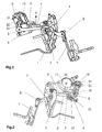
- FIG. 1 and 2 is a part of a circuit breaker after removing an arc quenching device and a surrounding its active parts housing shown.
- This part of the circuit breaker essentially shows a contact arrangement with two series-connected switching points 1, 2 and a switch housing carrying a movable contact unit 3.
- a not apparent release spring 4 is a release latch of the latch mechanism biased with a force acting in the arrow direction K.
- On the trigger finger 4 acts when triggered in a setting module 6 of an overcurrent release fixedly mounted two armed trained (Fig.2) release lever 5.
- This overcurrent trip also includes a Auslettebimetallfeder 7, which is loaded with a guided current in the switch, and a transmission 8, which the Auslettesbimetallfeder 7 and the release lever 5 positively coupled with each other.
- the adjustment module 6 has an insertable into the circuit breaker housing 9. This module housing accommodates a bimetallic spring 10 designed in the manner of a U for temperature compensation and also a part of the linkage gear 8. The triggering lever 5 and a lever 15 of the linkage 8 are guided through the module housing 9.
- a shift lever system 12 can be seen, which is hinged to the movable contact unit 3 and the manual switching on the circuit breaker with simultaneous charging of a movable contact unit 3 acts with a biasing force spring accumulator.
- the U-shaped compensation bimetallic spring 10 and a guide lever 11 are mounted rotatably about an adjustment axis 13 in the interior of the module housing 9.
- the right leg of the U is supported at its upper end to a lever operable by a knob 14.
- the Kompensationsbimetallfeder 10 can be pivoted in the drawing plane to the adjustment axis 13.
- the left leg of the U is freely movable in the plane of the drawing and pivots at a temperature change due to the formation of the U as a bimetal about the adjustment axis 13.
- the guide lever 11 has a cooperating with the left leg of the U stop 16, which during operation of the switch on this leg rests.
- the lever 15 is hinged at its end facing away from the axis 17 to a transmission lever 20 of the linkage 8. At least two of the levers of the linkage 8, z. B. 15 and 20 are detachably connected together.
- the coupling gear 8 can be easily separated or assembled by loosening or closing a hinge connection between the two levers 15 and 20 and the adjustment module 6 accordingly removed from the circuit breaker or used in this switch.
- a drive lever 21 of the linkage 8 is located.
- the pivot point 22 of this drive lever is fixedly mounted in the switch.
- a pivotable about the pivot end 22 of the drive lever 21 carries a biased by the Auslettesbimetallfeder 7 stop 23 and a non-designated connection element for hinging the transmission lever 20th
- the loaded with the upward biasing force K trigger finger 4 is held fixed regardless of the setting 6.
- an arm 51 projecting from the module housing 9 of the two-armed release lever 5 is pressed downwards in a clockwise direction for triggering.
- the second Arm 52 of the release lever 5 is driven by the guided into the interior of the module housing 9 part of the lever 15 for actuating the release finger 4 in a clockwise direction.
- the stop 16 and correspondingly also the lever 15 and the axis 17 are displaced by turning the adjusting knob 14 on a circular arc 24 shown in FIG. Center point and radius of the associated circle are determined by the adjustment axis 13 and the distance defined by the guide lever 11 between the adjustment axis 13 and the shaft 17. If a higher current set or increases the ambient temperature, then move stop 16, lever 15 and axis 17 on the circular arc 24 in the counterclockwise direction. This results in a distance between an apparent from Fig.7 arm 52 of the release lever 5 and a cut in Fig.7 part of the lever 15th
- the opening angle of the U. is also increased Ambient temperature, so the opening angle decreases.
- the stop 16 resting against the free limb of the compensation bimetallic spring 10 is guided to the left and thus a distance (not visible from FIG. 7) between the arm 52 of the release lever 5 and the Lever 15 is formed. Since at a temperature change at the same time but also the Auslettesbimetallfeder 7 in the direction shown in Figure 6 direction, ie to the right, bends, this distance is reversed by a rotation of the lever 15 in the counterclockwise direction.
- the rod 18 held on the guide lever 11 transmits to the adjacent switch poles the adjustment parameters required for the temperature compensation and determined by the ambient temperature and / or the maximum permissible rated current. It also causes the same setting at these switch poles as the compensation bimetallic spring 10 and the manual rated current setting.
Landscapes
- Breakers (AREA)
- Emergency Protection Circuit Devices (AREA)
- Thermally Actuated Switches (AREA)
Abstract
Description
- Die vorliegende Erfindung bezieht sich auf das Gebiet der Schutzschalter für Niederspannungsverteilnetze. Sie betrifft ein Einstellmodul zum Einbau in einen Schutzschalter mit einer Überstromauslösung auf der Basis einer temperaturkompensierten Auslösebimetallfeder sowie eine Überstromauslösung mit einem solchen Einstellmodul und einen Schutzschalter mit dieser Überstromauslösung.
- In Niederspannungsverteilnetzen dienen als Installationseinbauschalter ausgeführte Schutzschalter dem raschen und zuverlässigen Schutz von unter Niederspannung stehenden Leitungen, Motoren, Apparaten und Anlagen vor den Folgen von Überlast und Kurzschlussströmen. Sie weisen jeweils zumeist einen thermischen Auslöser mit einer Bimetallfeder auf, einen elektromagnetischen Auslöser mit einer Spule und einem Schlaganker und eine mit einer Löscheinrichtung zusammenwirkende Kontaktanordnung. Diese Kontaktanordnung wird beim Auftreten eines thermischen Überstroms im allgemeinen dadurch geöffnet, dass der thermische Auslöser an einem bestimmten Zeitpunkt das Entklinken eines auf die Kontaktanordnung wirkenden Schaltschlosses veranlasst. Für eine genaue Erfassung des Auslösezeitpunktes hat es sich bewährt, eine zusätzliche Bimetallfeder vorzusehen, welche ein durch die Umgebungstemperatur hervorgerufenes Ausbiegen der Auslösebimetallfeder kompensiert.
- Ein Schutzschalter mit einer Überstromauslösung auf der Basis einer Bimetallfeder ist in EP 0 316 719 A1 beschrieben. Der beschriebene Schutzschalter weist einen der Heizwirkung des Schalterstroms ausgesetzten Auslösebimetall auf, der beim Auftreten eines Überstroms so stark verbogen wird, dass über einen Auslösehebel ein Öffnen des Schalters veranlasst wird. Um den Einfluss der Umgebungstemperatur auszugleichen, ist ein Ausgleichsbimetall vorgesehen, das zur Einstellung des auf den festgelegten Überstrom ansprechenden Auslösebimetalls dient. Dieser Auslösebimetall ist im Auslöseweg zwischen dem Auslösebimetall und dem Auslösehebel angeordnet.
- Einen weiteren Schutzschalter mit einer Überstromauslösung auf der Basis einer Bimetallfeder zeigt EP 0 616 350 A1. Der beschriebene Schutzschalter enthält eine zumindest zum Teil vom Schalterstrom durchflossene Bimetallfeder. Diese Feder verbiegt sich beim Auftreten eines langandauernden Überstroms und entklinkt so über einen Stift ein Schaltschloss einer in Einschaltzustand des Schalters stromführenden Kontaktanordnung.
- Der Erfindung, wie sie in den Patentansprüchen angegeben ist, liegt die Aufgabe zugrunde, ein Einstellmodul zum Einbau in einen Schutzschalter mit einer temperaturkompensierten Überstromauslösung, eine Überstromauslösung mit einem solchen Einstellmodul und einen Schutzschalter mit dieser Überstromauslösung zu schaffen, welche einfach herstellbar sind und welche zugleich eine einfache Einstellung der Temperaturkompensation und/oder eines von der Leistung des Schalters abhängigen thermischen Nennstroms ermöglichen.
- Das Einstellmodul nach der Erfindung weist ein in den Schutzschalter einsetzbares Gehäuse auf, nimmt dieses Modulgehäuse eine Bimetallfeder zur Temperaturkompensation sowie einen Teil eines Koppelgetriebes der Überstromauslösung auf und sind durch das Modulgehäuse ein mit einem Schaltschloss des Schutzschalters zusammenwirkender erster Arm eines zweiarmigen Auslösehebels der Überstromauslösung und mindestens ein erster Hebel des Koppelgetriebes geführt. Durch diese Massnahmen wird erreicht, dass das Einstellmodul unabhängig vom Schutzschalter hergestellt und mit geringem Aufwand in den Schutzschalter eingesetzt oder daraus wieder entfernt werden kann. Die Herstellkosten der Überstromauslösung bzw. des mit dieser Überstromauslösung ausgerüsteten Schutzschalters werden so erheblich reduziert. Mit dem Einstellmodul lässt sich zugleich ein von der Leistungsklasse des Schalters abhängiger thermischer Nennstrom bequem einstellen und/oder der Einfluss der Umgebungstemperatur in sicherer und einfacher Weise kompensieren.
- Ein einfacher Aufbau des Einstellmoduls und eine bequeme Einstellung der Temperaturkompensation und/oder des thermischen Nennstroms werden ermöglicht, wenn die Kompensationsbimetallfeder um eine Einstellachse drehbar gelagert ist und mit einem ersten ihrer beiden Enden lageveränderlich mit einem Einstellknopf zusammenwirkt.
- Mit Vorteil ist die Kompensationsbimetallfeder nach Art eines U, einer Spirale oder einer Wendel ausgeführt. Zum einen wird so ein besonders kompakter Aufbau des Einstellmoduls ermöglicht. Zum anderen werden so auch der Verstellweg und die Ausbiegelänge gegenüber einer gestreckt ausgebildeten Bimetallfeder vergrössert und dementsprechend die Auslösegenauigkeit der das Einstellmodul enthaltenden Überstromauslösung resp. des mit dieser Auslösung ausgerüsteten Schutzschalters erheblich verbessert.
- Eine durch Zusammenstecken einfacher Ausgangskomponenten, wie insbesondere polymerer Spritzgussteile und metallener Standardbauelemente, insbesondere Metallachsen und Bimetallfedern, kostengünstig zu fertigende Ausführungsform des Einstellmoduls ist durch folgende Merkmale gekennzeichnet:
- die Kompensationsbimetallfeder ist nach Art eines U ausgebildet und weist eine kreisbogenförmig ausgebildete Basis auf,
- die Basis des U ist um die Einstellachse schwenkbar an einem am Koppelgetriebe angelenkten Führungshebel gehalten, und
- der Führungshebel ist ebenfalls um die Einstellachse schwenkbar und liegt mit seinem schwenkbaren Ende an dem als Schenkel des U ausgebildeten zweiten Ende der Kompensationsbimetallfeder an.
- Für eine gute Stabilität des Koppelgetriebes und für einen sicheren Betrieb des Einstellmoduls ist es von Vorteil, wenn der Führungshebel gabelförmig ausgebildet ist und zwei um die Einstellachse schwenkbare Gabelarme aufweist zum Anlenken des zwischen den Gabelarmen schwenkbar gehaltenen ersten Hebels des Koppelgetriebes.
- Aus fertigungstechnischen Gründen sollte der erste Hebel mit einem zweiten Hebel des Koppelgetriebes lösbar verbunden sein. Das Einstellmodul kann dann in einfacher Weise in den Schutzschalter eingebaut oder wieder aus diesen Schalter ausgebaut werden.
- An einem ausserhalb des Modulgehäuses angeordneten ersten beider Gabelarme des Führungshebels ist mit Vorteil eine Halterung zur Aufnahme einer Stange vorgesehen. Diese Stange stellt die Verbindung zu benachbarten Schalterpolen des Schutzschalters her und übertragt auf diese Pole die zur Temperaturkompensation benötigten und durch die Umgebungstemperatur und/oder den zulässigen Nennstrom bestimmten Parameter. Separate Einstellmodule für die Nachbarpole sind dann nicht erforderlich.
- Ist an einem innerhalb des Modulgehäuses angeordneten zweiten beider Gabelarme des Führungshebels ein an die Kompensationsbimetallfeder führbarer Anschlag angeordnet, so können die Umgebungstemperatur sicher kompensiert und der thermische Nennstrom leicht eingestellt werden.
- Bei einer mit einem Einstellmodul nach der Erfindung versehenen Überstromauslösung weist das Koppelgetriebe mit Vorteil einen einarmigen Antriebshebel auf, dessen Drehpunkt am Schutzschalter feststehend gelagert ist, und dessen um den Drehpunkt schwenkbares Ende ein Verbindungselement zum Anlenken eines Übertragungshebels trägt. Eine sichere Wirkungsweise der Überstromauslösung ist so gewährleistet. Dadurch, dass der Übertragungshebel lösbar am Antriebshebel und an einem am Einstellmodul gehaltenen Hebel des Koppelgetriebes angelenkt ist, kann diese Überstromauslösung rasch montiert oder demontiert werden.
- Anhand von Zeichnungen werden nachfolgend zwei Ausführungsbeispiele der Erfindung näher erläutert. Hierbei zeigt:
- Fig.1
- in perspektivischer Ansicht Aktivteile eines Schutzschalters mit einer Überstromauslösung enthaltend eine erste Ausführungsform eines Einstellmoduls 6 nach der Erfindung,
- Fig.2
- eine im wesentlichen in entgegengesetzter Richtung geführte Ansicht des Schutzschalters gemäss Fig.1, bei der zusätzlich ein manuell betätigbares Schalthebelsystem 12 dargestellt ist,
- Fig.3
- eine in Richtung einer Einstellachse 13 geführte Ansicht des Einstellmoduls 6 gemäss Fig. 1 nach dem Entfernen eines Teils des Modulgehäuses 9,
- Fig.4
- das Modul gemäss Fig.3 nach dem Entfernen eines Führungshebels 11,
- Fig.5
- eine Aufsicht von rechts auf die Überstromauslösung des Schutzschalters gemäss Fig.1 nach dem Entfernen von Teilen des Schutzschalters,
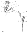
- Fig.6
- eine in Richtung einer Einstellachse 13 geführte Ansicht der Überstromauslösung des Schutzschalter gemäss Fig.5, und
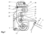
- Fig.7
- eine Aufsicht auf einen Schnitt durch das Modul gemäss Fig.3, welcher durch einen Hebel 15 eines Koppelgetriebes 8 geführt ist, und
- In allen Figuren beziehen sich gleiche Bezugszeichen auf gleichwirkende Teile. In den Figuren 1 und 2 ist ein Teil eines Schutzschalters nach dem Entfernen einer Lichtbogenlöscheinrichtung und eines seine Aktivteile umgebenden Gehäuses dargestellt. Dieser Teil des Schutzschalters zeigt im wesentlichen eine Kontaktanordnung mit zwei in Serie geschalteten Schaltstellen 1, 2 und mit einer ein Schaltschloss tragenden beweglichen Kontakteinheit 3. Durch eine nicht ersichtliche Auslösefeder ist ein Auslösefinger 4 einer Verklinkung des Schaltschlosses mit einer in Pfeilrichtung wirkenden Kraft K vorgespannt. Auf den Auslösefinger 4 wirkt beim Auslösen ein in einem Einstellmodul 6 einer Überstromauslösung feststehend gelagerter zweiarmig ausgebildeter (Fig.2) Auslösehebel 5. Diese Überstromauslösung umfasst auch eine Auslösebimetallfeder 7, die mit einem im Schalter geführten Strom belastbar ist, sowie ein Getriebe 8, welches die Auslösebimetallfeder 7 und den Auslösehebel 5 kraftschlüssig miteinander koppelt. Das Einstellmodul 6 weist ein in den Schutzschalter einsetzbares Gehäuse 9 auf. Dieses Modulgehäuse nimmt eine nach Art eines U ausgebildete Bimetallfeder 10 zur Temperaturkompensation auf sowie einen Teil des Koppelgetriebes 8. Der Auslösehebel 5 und ein Hebel 15 des Koppelgetriebes 8 sind durch das Modulgehäuse 9 geführt.
- Aus Fig.2 ist auch ein Schalthebelsystem 12 ersichtlich, welches an die bewegliche Kontakteinheit 3 angelenkt ist und dem manuellen Einschalten des Schutzschalters unter gleichzeitigem Aufladen eines die bewegliche Kontakteinheit 3 mit einer Vorspannkraft beaufschlagenden Federspeichers dient. Darüber hinaus ist aus Fig.2 auch ersichtlich, dass die U-förmige Kompensationsbimetallfeder 10 und ein Führungshebel 11 um eine Einstellachse 13 drehbar im Inneren des Modulgehäuses 9 gelagert sind. Der rechte Schenkel des U ist mit seinem oberen Ende an einem von einem Einstellknopf 14 betätigbaren Hebel abgestützt. Durch Drehen des Einstellknopfs 14 kann so die Kompensationsbimetallfeder 10 in der Zeichnungsebene um die Einstellachse 13 geschwenkt werden. Der linke Schenkel des U ist in der Zeichnungsebene frei beweglich und schwenkt bei einer Temperaturänderung infolge der Ausbildung des U als Bimetall um die Einstellachse 13. Der Führungshebel 11 weist einen mit dem linken Schenkel des U zusammenwirkenden Anschlag 16 auf, welcher bei Betrieb des Schalters auf diesem Schenkel aufliegt.
- Der weitere Aufbau und die Wirkungsweise des Einstellmoduls 6 sowie die mit diesem Modul ausgerüstete Überstromauslösung werden nachfolgend anhand der Figuren 3 bis 7 erläutert.
- Aus den Figuren 3 und 4 ist die im Inneren des Modulgehäuses 9 feststehend gehaltene Einstellachse 13 ersichtlich, an welcher der Drehpunkt des Führungshebels 11 (Fig.3) und die Basis des U der Kompensationsbimetallfeder 10 schwenkbar gelagert sind. Fig.5 kann entnommen werden, dass sich der Führungshebel 11 an seinem von der Einstellachse 13 abgewandten Ende in zwei Arme 19, 19' aufgabelt. Ein im Modulgehäuse 9 angeordneter Arm 19' (auch aus den Figuren 2 und 3 ersichtlich) der Gabel trägt den Anschlag 16 sowie eine Lagerstelle für eine Achse 17. Ein ausserhalb des Modulgehäuses 9 angeordneter Arm 19 der Gabel (auch aus den Figuren 1 und 3 ersichtlich) trägt eine zweite Lagerstelle der Achse 17 sowie eine Halterung zur Aufnahme einer Stange 18. Ersichtlich erstreckt sich die Achse 17 durch ein Ende des Hebels 15. Dieses Ende des Hebels 15 ist daher zwischen den beiden Armen 19, 19' der Gabel drehbar gehalten und ersichtlich von aussen durch das Modulgehäuse 9 in dessen Inneres geführt.. Die Stange 18 stellt die Verbindung zu benachbarten Schalterpolen des Schutzschalters her.
- Der Hebel 15 ist an seinem von der Achse 17 abgewandten Ende an einen Übertragungshebel 20 des Koppelgetriebes 8 angelenkt. Mindestens zwei der Hebel des Koppelgetriebes 8, z. B. 15 und 20, sind lösbar miteinander verbunden. Das Koppelgetriebe 8 kann so durch Lösen oder Schliessen einer Gelenkverbindung zwischen den beiden Hebeln 15 und 20 leicht aufgetrennt oder zusammengebaut werden und das Einstellmodul 6 entsprechend aus dem Schutzschalter entfernt oder in diesen Schalter eingesetzt werden.
- In die Figuren 5 und 6 ist ein Antriebshebel 21 des Koppelgetriebes 8 eingezeichnet. Der Drehpunkt 22 dieses Antriebshebels ist feststehend im Schalter gelagert. Ein um den Drehpunkt 22 schwenkbares Ende des Antriebshebels 21 trägt einen von der Auslösebimetallfeder 7 beaufschlagbaren Anschlag 23 sowie ein nicht bezeichnetes Verbindungselement zum Anlenken des Übertragungshebels 20.
- Der mit der nach oben wirkenden Vorspannkraft K belastete Auslösefinger 4 ist unabhängig vom Einstellmodul 6 fix gehalten. In der Darstellung gemäss Fig.7 wird ein aus dem Modulgehäuse 9 ragender Arm 51 des zweiarmig ausgebildeten Auslösehebels 5 zum Auslösen im Uhrzeigersinn nach unten gedrückt. Der zweite Arm 52 des Auslösehebels 5 wird durch das ins Innere des Modulgehäuses 9 geführte Teil des Hebels 15 zum Betätigen des Auslösefingers 4 im Uhrzeigersinn angetrieben.
- Mit dem Einstellknopf 14 wird der vom Schutzschalter noch beherrschbare Überstrom eingestellt. In der Darstellung gemäss Fig.2 wird durch Drehen des Einstellknopfs 14 der rechte Schenkel des U und damit auch die gesamte Kompensationsbimetallfeder 10 in der Zeichnungsebene geschwenkt. Ist der Schalter zum Tragen grosser Nennströme, beispielsweise 63 A, bestimmt, so wird das U im Uhrzeigersinn, d. h. nach rechts, geschwenkt. Ist der Schalter zum Tragen kleinerer Ströme bemessen, beispielsweise 40 A, so wird das U im Gegenuhrzeigersinn, d. h. nach links, geschwenkt.
- Der Anschlag 16 und entsprechend auch der Hebel 15 bzw. die Achse 17 werden durch Verdrehen des Einstellknopfes 14 auf einem aus Fig.7 ersichtlichen Kreisbogen 24 verschoben. Mittelpunkt und Radius des zugeordneten Kreises sind bestimmt durch die Einstellachse 13 und den durch den Führungshebel 11 festgelegten Abstand zwischen der Einstellachse 13 und der Welle 17. Wird ein höherer Strom eingestellt oder erhöht sich die Umgebungstemperatur, so bewegen sich Anschlag 16, Hebel 15 und Achse 17 auf dem Kreisbogen 24 im Gegenuhrzeigersinn. Dadurch entsteht ein Abstand zwischen einem aus Fig.7 ersichtlichen Arm 52 des Auslösehebels 5 und einem in Fig.7 geschnitten dargestellten Teil des Hebels 15.
- Tritt bei Betrieb des Schutzschalters Überstrom auf, so verbiegt sich die Auslösebimetallfeder 7 nach rechts (Fig.6) und werden nun der mit seinem Anschlag 23 an der Auslösebimetallfeder 7 abgestützte Antriebshebel 21 und damit auch der Übertragungshebel 20 nach rechts geführt. Entsprechend wird der Hebel 15 im Gegenuhrzeigersinn gedreht und über den nun im Uhrzeigersinn gedrehten Auslösehebel 5 (Fig.7) eine nach unten gerichtete Schwenkbewegung des Auslösefingers 4 bewirkt, wodurch das Schaltschloss entklinkt und der Schutzschalter geöffnet wird.
- Verändert sich beim Betrieb des Schutzschalters die Umgebungstemperatur, so verändert sich auch der Öffnungswinkel des U. Erhöht sich beispielsweise die Umgebungstemperatur, so verringert sich der Öffnungswinke. Wie aus der Darstellung des Einstellmoduls gemäss Fig.7 ersichtlich ist, wird der am freien Schenkel der Kompensationsbimetallfeder 10 anliegende Anschlag 16 nach links geführt und so ein (aus der Fig.7 nicht mehr ersichtlicher Abstand) zwischen dem Arm 52 des Auslösehebels 5 und dem Hebel 15 gebildet. Da bei einer Temperaturänderung sich zugleich aber auch die Auslösebimetallfeder 7 in der aus Fig.6 ersichtlichen Richtung, d. h. nach rechts, verbiegt, wird dieser Abstand durch eine Drehung des Hebels 15 im Gegenuhrzeigersinn rückgängig gemacht.
- Dadurch, dass die Kompensationsbimetallfeder 10 nach Art eines U gebogen ist, werden ein grosser Verstellweg und eine grosse Ausbiegelänge und damit eine hohe Ansprechempfindlichkeit der Überstromauslösung erreicht. Gegenüber einem vergleichbaren Schutzschalter mit einer ungebogenen Kompensationsbimetallfeder wird Platz eingespart, da das Einstellmodul besonders kompakt ausgebildet ist.
- Die am Führungshebel 11 gehaltene Stange 18 übertragt auf die benachbarten Schalterpole die zur Temperaturkompensation benötigten und durch die Umgebungstemperatur und/oder den maximal zulässigen Nennstrom bestimmten Einstellparameter. Sie bewirkt so auch an diesen Schalterpolen die gleiche Einstellung wie die Kompensationsbimetallfeder 10 und die manuelle Nennstromeinstellung.
-
- 1, 2
- Schaltstellen
- 3
- Kontakteinheit
- 4
- Auslösefinger
- 5
- Auslösehebel
- 51,52
- Hebelarme
- 6
- Einstellmodul
- 7
- Auslösebimetallfeder
- 8
- Koppelgetriebe
- 9
- Modulgehäuse
- 10
- Kompensationsbimetallfeder
- 11
- Führungshebel
- 12
- Schalthebelsystem
- 13
- Einstellachse
- 14
- Einstellknopf
- 15
- Hebel
- 16
- Anschlag
- 17
- Welle
- 18
- Stange
- 19, 19'
- Gabelarme
- 20
- Übertragungshebel
- 21
- Antriebshebel
- 22
- Drehpunkt
- 23
- Anschlag
- 24
- Kreisbogen
Claims (10)
- Einstellmodul (6) zum Einbau in einen Schutzschalter mit einer Überstromauslösung auf der Basis einer temperaturkompensierten Auslösebimetallfeder (7), dadurch gekennzeichnet, dass das Modul (6) ein in den Schutzschalter einsetzbares Gehäuse (9) aufweist, dass das Modulgehäuse (9) eine Bimetallfeder (10) zur Temperaturkompensation und einen Teil eines Koppelgetriebes (8) der Überstromauslösung aufnimmt, und dass durch das Modulgehäuse (9) ein mit einem Schaltschloss des Schutzschalters zusammenwirkender erster Arm (51) eines zweiarmigen Auslösehebels (5) der Überstromauslösung und mindestens ein erster Hebel (15) des Koppelgetriebes (8) geführt sind.
- Modul nach Anspruch 1, dadurch gekennzeichnet, dass die Kompensationsbimetallfeder (10) um eine Einstellachse (13) drehbar gelagert ist und mit einem ersten ihrer beiden Enden lageveränderlich mit einem Einstellknopf (14) zusammenwirkt.
- Modul nach Anspruch 2, dadurch gekennzeichnet, dass die Kompensationsbimetallfeder (10) nach Art eines U, einer Spirale oder einer Wendel ausgeführt ist.
- Modul nach Anspruch 3, dadurch gekennzeichnet, dass bei Ausbildung der Kompensationsbimetallfeder (10) nach Art eines U die Basis des U kreisbogenförmig ausgebildet und um die Einstellachse (13) schwenkbar an einem am Koppelgetriebe (8) angelenkten Führungshebel (11) gehalten ist, der ebenfalls um die Einstellachse (13) schwenkbar ist und mit seinem schwenkbaren Ende an dem als Schenkel des U ausgebildeten zweiten Ende der Kompensationsbimetallfeder (10) anliegt.
- Modul nach Anspruch 4, dadurch gekennzeichnet, dass der Führungshebel (11) gabelförmig ausgebildet ist und zwei um die Einstellachse (13) schwenkbare Gabelarme (19, 19') aufweist zum Anlenken des zwischen den Gabelarmen (19, 19') schwenkbar gehaltenen ersten Hebels (15) des Koppelgetriebes (8).
- Modul nach Anspruch 5, dadurch gekennzeichnet, dass der erste Hebel (15) mit einem zweiten Hebel (20) des Koppelgetriebes (8) lösbar verbunden ist.
- Modul nach einem der Ansprüche 5 oder 6, dadurch gekennzeichnet, dass an einen ausserhalb des Modulgehäuses (9) angeordneten ersten (19) beider Gabelarme (19, 19') des Führungshebels (11) eine Halterung zur Aufnahme einer Stange (18) vorgesehen ist.
- Modul nach einem der Ansprüche 5 bis 7, dadurch gekennzeichnet, dass an einem innerhalb des Modulgehäuses (9) angeordneten zweiten (19') beider Gabelarme (19, 19') des Führungshebels (11) ein an die Kompensationsbimetallfeder (10) führbarer Anschlag (16) angeordnet ist.
- Überstromauslösung mit einem Modul nach einem der Ansprüche 1 bis 8, dadurch gekennzeichnet, dass das Koppelgetriebe (8) einen Antriebshebel (21) aufweist, dessen Drehpunkt (22) am Schutzschalter feststehend gelagert, und dessen um den Drehpunkt (22) schwenkbares Ende ein Verbindungselement zum Anlenken eines zweiten Hebels (20) des Koppelgetriebes (8) trägt.
- Schutzschalter mit der Überstromauslösung nach Anspruch 9.
Priority Applications (4)
| Application Number | Priority Date | Filing Date | Title |
|---|---|---|---|
| AT04405612T ATE377256T1 (de) | 2004-09-29 | 2004-09-29 | Einstellmodul für eine überstromauslösung eines schutzschalters |
| ES04405612T ES2295808T3 (es) | 2004-09-29 | 2004-09-29 | Modulo de ajuste para un disparador de sobreintensidad para un interruptor de proteccion. |
| DE502004005372T DE502004005372D1 (de) | 2004-09-29 | 2004-09-29 | Einstellmodul für eine Überstromauslösung eines Schutzschalters |
| EP04405612A EP1643525B1 (de) | 2004-09-29 | 2004-09-29 | Einstellmodul für eine Überstromauslösung eines Schutzschalters |
Applications Claiming Priority (1)
| Application Number | Priority Date | Filing Date | Title |
|---|---|---|---|
| EP04405612A EP1643525B1 (de) | 2004-09-29 | 2004-09-29 | Einstellmodul für eine Überstromauslösung eines Schutzschalters |
Publications (2)
| Publication Number | Publication Date |
|---|---|
| EP1643525A1 true EP1643525A1 (de) | 2006-04-05 |
| EP1643525B1 EP1643525B1 (de) | 2007-10-31 |
Family
ID=34932304
Family Applications (1)
| Application Number | Title | Priority Date | Filing Date |
|---|---|---|---|
| EP04405612A Expired - Lifetime EP1643525B1 (de) | 2004-09-29 | 2004-09-29 | Einstellmodul für eine Überstromauslösung eines Schutzschalters |
Country Status (4)
| Country | Link |
|---|---|
| EP (1) | EP1643525B1 (de) |
| AT (1) | ATE377256T1 (de) |
| DE (1) | DE502004005372D1 (de) |
| ES (1) | ES2295808T3 (de) |
Citations (2)
| Publication number | Priority date | Publication date | Assignee | Title |
|---|---|---|---|---|
| EP0317660A1 (de) * | 1987-11-25 | 1989-05-31 | Square D Company (Deutschland) Gmbh | Schütz |
| DE10158255A1 (de) * | 2000-11-29 | 2002-07-18 | Fuji Electric Co Ltd | Leitungsschutzschalter mit Sofortauslösung |
-
2004
- 2004-09-29 AT AT04405612T patent/ATE377256T1/de not_active IP Right Cessation
- 2004-09-29 DE DE502004005372T patent/DE502004005372D1/de not_active Expired - Lifetime
- 2004-09-29 EP EP04405612A patent/EP1643525B1/de not_active Expired - Lifetime
- 2004-09-29 ES ES04405612T patent/ES2295808T3/es not_active Expired - Lifetime
Patent Citations (2)
| Publication number | Priority date | Publication date | Assignee | Title |
|---|---|---|---|---|
| EP0317660A1 (de) * | 1987-11-25 | 1989-05-31 | Square D Company (Deutschland) Gmbh | Schütz |
| DE10158255A1 (de) * | 2000-11-29 | 2002-07-18 | Fuji Electric Co Ltd | Leitungsschutzschalter mit Sofortauslösung |
Also Published As
| Publication number | Publication date |
|---|---|
| DE502004005372D1 (de) | 2007-12-13 |
| ATE377256T1 (de) | 2007-11-15 |
| ES2295808T3 (es) | 2008-04-16 |
| EP1643525B1 (de) | 2007-10-31 |
Similar Documents
| Publication | Publication Date | Title |
|---|---|---|
| DE69419670T2 (de) | Betätigungsmechanismus für elektrischen Modulschutzschalter | |
| EP0543208B1 (de) | Schutzschalter mit Schaltwippe | |
| DE670790C (de) | Thermisch wirkender Selbstschalter | |
| EP2345057B1 (de) | Elektrisches überstromrelais mit einem gelagerten betätigungshebel | |
| WO2003007322A1 (de) | Schaltgerät mit einem schaltschloss | |
| DE3105774C2 (de) | ||
| DE10032323A1 (de) | Ein- und Ausschaltmechanismus für einen Ausschalter | |
| EP2027590B1 (de) | Thermischer und/oder magnetischer überlastauslöser | |
| DE10234864B4 (de) | Schutzschalter | |
| DE3119165C2 (de) | Selbstschalter als Baueinheit aus einem Leitungsschutzschalter sowie Hilfs- und Signalschaltern | |
| EP1643525B1 (de) | Einstellmodul für eine Überstromauslösung eines Schutzschalters | |
| WO2006053648A1 (de) | Elektrisches installationsschaltgerät | |
| EP1328956B1 (de) | Strombegrenzender niederspannungs-leistungsschalter | |
| EP0454018B1 (de) | Elektrisches Schaltgerät | |
| DE3105524C2 (de) | Leistungsschalter | |
| DE19534612C2 (de) | Stromkreisunterbrecher | |
| EP0091040A2 (de) | Überstromschutzschalter | |
| DE29917173U1 (de) | Betätigungseinrichtung für ein elektrisches Überstromrelais | |
| DE69836247T2 (de) | Antriebsvorrichtung eines elektrischen Schutzgerätes wie zum Beispiel eines Leistungsschalters mit einem Auslöseanzeigemittel sowie mit einer solchen Vorrichtung ausgerüsteter Leistungsschalter | |
| EP0473619A1 (de) | Schaltmechanismus für einen leitungsschutzschalter. | |
| DE4339425A1 (de) | Schaltschloß für einen Fehlerstromschutzschalter | |
| DE10061783C1 (de) | Verriegelungsvorrichtung | |
| DE102005046640B4 (de) | Elektrisches Installationsgerät | |
| DE3002122A1 (de) | Flammhemmende polycarbonat-zusammensetzungen | |
| DE2857067C2 (de) | Motorschutzschalter |
Legal Events
| Date | Code | Title | Description |
|---|---|---|---|
| PUAI | Public reference made under article 153(3) epc to a published international application that has entered the european phase |
Free format text: ORIGINAL CODE: 0009012 |
|
| AK | Designated contracting states |
Kind code of ref document: A1 Designated state(s): AT BE BG CH CY CZ DE DK EE ES FI FR GB GR HU IE IT LI LU MC NL PL PT RO SE SI SK TR |
|
| AX | Request for extension of the european patent |
Extension state: AL HR LT LV MK |
|
| 17P | Request for examination filed |
Effective date: 20060819 |
|
| 17Q | First examination report despatched |
Effective date: 20061103 |
|
| AKX | Designation fees paid |
Designated state(s): AT BE BG CH CY CZ DE DK EE ES FI FR GB GR HU IE IT LI LU MC NL PL PT RO SE SI SK TR |
|
| GRAP | Despatch of communication of intention to grant a patent |
Free format text: ORIGINAL CODE: EPIDOSNIGR1 |
|
| GRAS | Grant fee paid |
Free format text: ORIGINAL CODE: EPIDOSNIGR3 |
|
| GRAA | (expected) grant |
Free format text: ORIGINAL CODE: 0009210 |
|
| AK | Designated contracting states |
Kind code of ref document: B1 Designated state(s): AT BE BG CH CY CZ DE DK EE ES FI FR GB GR HU IE IT LI LU MC NL PL PT RO SE SI SK TR |
|
| REG | Reference to a national code |
Ref country code: GB Ref legal event code: FG4D Free format text: NOT ENGLISH |
|
| REG | Reference to a national code |
Ref country code: IE Ref legal event code: FG4D Free format text: LANGUAGE OF EP DOCUMENT: GERMAN |
|
| REG | Reference to a national code |
Ref country code: CH Ref legal event code: EP |
|
| REF | Corresponds to: |
Ref document number: 502004005372 Country of ref document: DE Date of ref document: 20071213 Kind code of ref document: P |
|
| GBT | Gb: translation of ep patent filed (gb section 77(6)(a)/1977) |
Effective date: 20080116 |
|
| NLV1 | Nl: lapsed or annulled due to failure to fulfill the requirements of art. 29p and 29m of the patents act | ||
| ET | Fr: translation filed | ||
| REG | Reference to a national code |
Ref country code: ES Ref legal event code: FG2A Ref document number: 2295808 Country of ref document: ES Kind code of ref document: T3 |
|
| PG25 | Lapsed in a contracting state [announced via postgrant information from national office to epo] |
Ref country code: NL Free format text: LAPSE BECAUSE OF FAILURE TO SUBMIT A TRANSLATION OF THE DESCRIPTION OR TO PAY THE FEE WITHIN THE PRESCRIBED TIME-LIMIT Effective date: 20071031 Ref country code: SE Free format text: LAPSE BECAUSE OF FAILURE TO SUBMIT A TRANSLATION OF THE DESCRIPTION OR TO PAY THE FEE WITHIN THE PRESCRIBED TIME-LIMIT Effective date: 20080131 |
|
| PG25 | Lapsed in a contracting state [announced via postgrant information from national office to epo] |
Ref country code: PT Free format text: LAPSE BECAUSE OF FAILURE TO SUBMIT A TRANSLATION OF THE DESCRIPTION OR TO PAY THE FEE WITHIN THE PRESCRIBED TIME-LIMIT Effective date: 20080331 Ref country code: PL Free format text: LAPSE BECAUSE OF FAILURE TO SUBMIT A TRANSLATION OF THE DESCRIPTION OR TO PAY THE FEE WITHIN THE PRESCRIBED TIME-LIMIT Effective date: 20071031 Ref country code: BG Free format text: LAPSE BECAUSE OF FAILURE TO SUBMIT A TRANSLATION OF THE DESCRIPTION OR TO PAY THE FEE WITHIN THE PRESCRIBED TIME-LIMIT Effective date: 20080131 Ref country code: SI Free format text: LAPSE BECAUSE OF FAILURE TO SUBMIT A TRANSLATION OF THE DESCRIPTION OR TO PAY THE FEE WITHIN THE PRESCRIBED TIME-LIMIT Effective date: 20071031 |
|
| REG | Reference to a national code |
Ref country code: IE Ref legal event code: FD4D |
|
| PG25 | Lapsed in a contracting state [announced via postgrant information from national office to epo] |
Ref country code: DK Free format text: LAPSE BECAUSE OF FAILURE TO SUBMIT A TRANSLATION OF THE DESCRIPTION OR TO PAY THE FEE WITHIN THE PRESCRIBED TIME-LIMIT Effective date: 20071031 Ref country code: CZ Free format text: LAPSE BECAUSE OF FAILURE TO SUBMIT A TRANSLATION OF THE DESCRIPTION OR TO PAY THE FEE WITHIN THE PRESCRIBED TIME-LIMIT Effective date: 20071031 |
|
| PG25 | Lapsed in a contracting state [announced via postgrant information from national office to epo] |
Ref country code: SK Free format text: LAPSE BECAUSE OF FAILURE TO SUBMIT A TRANSLATION OF THE DESCRIPTION OR TO PAY THE FEE WITHIN THE PRESCRIBED TIME-LIMIT Effective date: 20071031 Ref country code: RO Free format text: LAPSE BECAUSE OF FAILURE TO SUBMIT A TRANSLATION OF THE DESCRIPTION OR TO PAY THE FEE WITHIN THE PRESCRIBED TIME-LIMIT Effective date: 20071031 |
|
| PLBE | No opposition filed within time limit |
Free format text: ORIGINAL CODE: 0009261 |
|
| STAA | Information on the status of an ep patent application or granted ep patent |
Free format text: STATUS: NO OPPOSITION FILED WITHIN TIME LIMIT |
|
| 26N | No opposition filed |
Effective date: 20080801 |
|
| PG25 | Lapsed in a contracting state [announced via postgrant information from national office to epo] |
Ref country code: IE Free format text: LAPSE BECAUSE OF FAILURE TO SUBMIT A TRANSLATION OF THE DESCRIPTION OR TO PAY THE FEE WITHIN THE PRESCRIBED TIME-LIMIT Effective date: 20071031 |
|
| PG25 | Lapsed in a contracting state [announced via postgrant information from national office to epo] |
Ref country code: GR Free format text: LAPSE BECAUSE OF FAILURE TO SUBMIT A TRANSLATION OF THE DESCRIPTION OR TO PAY THE FEE WITHIN THE PRESCRIBED TIME-LIMIT Effective date: 20080201 |
|
| PG25 | Lapsed in a contracting state [announced via postgrant information from national office to epo] |
Ref country code: FI Free format text: LAPSE BECAUSE OF FAILURE TO SUBMIT A TRANSLATION OF THE DESCRIPTION OR TO PAY THE FEE WITHIN THE PRESCRIBED TIME-LIMIT Effective date: 20071031 |
|
| BERE | Be: lapsed |
Owner name: ABB SCHWEIZ A.G. Effective date: 20080930 |
|
| PG25 | Lapsed in a contracting state [announced via postgrant information from national office to epo] |
Ref country code: MC Free format text: LAPSE BECAUSE OF NON-PAYMENT OF DUE FEES Effective date: 20080930 Ref country code: EE Free format text: LAPSE BECAUSE OF FAILURE TO SUBMIT A TRANSLATION OF THE DESCRIPTION OR TO PAY THE FEE WITHIN THE PRESCRIBED TIME-LIMIT Effective date: 20071031 |
|
| REG | Reference to a national code |
Ref country code: CH Ref legal event code: PL |
|
| PG25 | Lapsed in a contracting state [announced via postgrant information from national office to epo] |
Ref country code: BE Free format text: LAPSE BECAUSE OF NON-PAYMENT OF DUE FEES Effective date: 20080930 Ref country code: CY Free format text: LAPSE BECAUSE OF FAILURE TO SUBMIT A TRANSLATION OF THE DESCRIPTION OR TO PAY THE FEE WITHIN THE PRESCRIBED TIME-LIMIT Effective date: 20071031 |
|
| PG25 | Lapsed in a contracting state [announced via postgrant information from national office to epo] |
Ref country code: LI Free format text: LAPSE BECAUSE OF NON-PAYMENT OF DUE FEES Effective date: 20080930 Ref country code: AT Free format text: LAPSE BECAUSE OF NON-PAYMENT OF DUE FEES Effective date: 20080929 Ref country code: CH Free format text: LAPSE BECAUSE OF NON-PAYMENT OF DUE FEES Effective date: 20080930 |
|
| PG25 | Lapsed in a contracting state [announced via postgrant information from national office to epo] |
Ref country code: HU Free format text: LAPSE BECAUSE OF FAILURE TO SUBMIT A TRANSLATION OF THE DESCRIPTION OR TO PAY THE FEE WITHIN THE PRESCRIBED TIME-LIMIT Effective date: 20080501 Ref country code: LU Free format text: LAPSE BECAUSE OF NON-PAYMENT OF DUE FEES Effective date: 20080929 |
|
| PG25 | Lapsed in a contracting state [announced via postgrant information from national office to epo] |
Ref country code: TR Free format text: LAPSE BECAUSE OF FAILURE TO SUBMIT A TRANSLATION OF THE DESCRIPTION OR TO PAY THE FEE WITHIN THE PRESCRIBED TIME-LIMIT Effective date: 20071031 |
|
| PGFP | Annual fee paid to national office [announced via postgrant information from national office to epo] |
Ref country code: GB Payment date: 20150917 Year of fee payment: 12 Ref country code: ES Payment date: 20150928 Year of fee payment: 12 |
|
| REG | Reference to a national code |
Ref country code: FR Ref legal event code: PLFP Year of fee payment: 13 |
|
| GBPC | Gb: european patent ceased through non-payment of renewal fee |
Effective date: 20160929 |
|
| PG25 | Lapsed in a contracting state [announced via postgrant information from national office to epo] |
Ref country code: GB Free format text: LAPSE BECAUSE OF NON-PAYMENT OF DUE FEES Effective date: 20160929 |
|
| REG | Reference to a national code |
Ref country code: FR Ref legal event code: PLFP Year of fee payment: 14 |
|
| PG25 | Lapsed in a contracting state [announced via postgrant information from national office to epo] |
Ref country code: ES Free format text: LAPSE BECAUSE OF NON-PAYMENT OF DUE FEES Effective date: 20160930 |
|
| REG | Reference to a national code |
Ref country code: FR Ref legal event code: PLFP Year of fee payment: 15 |
|
| REG | Reference to a national code |
Ref country code: ES Ref legal event code: FD2A Effective date: 20181126 |
|
| PGFP | Annual fee paid to national office [announced via postgrant information from national office to epo] |
Ref country code: IT Payment date: 20190925 Year of fee payment: 16 Ref country code: DE Payment date: 20190918 Year of fee payment: 16 Ref country code: FR Payment date: 20190926 Year of fee payment: 16 |
|
| REG | Reference to a national code |
Ref country code: DE Ref legal event code: R119 Ref document number: 502004005372 Country of ref document: DE |
|
| PG25 | Lapsed in a contracting state [announced via postgrant information from national office to epo] |
Ref country code: DE Free format text: LAPSE BECAUSE OF NON-PAYMENT OF DUE FEES Effective date: 20210401 Ref country code: FR Free format text: LAPSE BECAUSE OF NON-PAYMENT OF DUE FEES Effective date: 20200930 |
|
| PG25 | Lapsed in a contracting state [announced via postgrant information from national office to epo] |
Ref country code: IT Free format text: LAPSE BECAUSE OF NON-PAYMENT OF DUE FEES Effective date: 20200929 |