EP1640783A2 - Système de projection optique pour un dispositif d'affichage d'images - Google Patents
Système de projection optique pour un dispositif d'affichage d'images Download PDFInfo
- Publication number
- EP1640783A2 EP1640783A2 EP05108540A EP05108540A EP1640783A2 EP 1640783 A2 EP1640783 A2 EP 1640783A2 EP 05108540 A EP05108540 A EP 05108540A EP 05108540 A EP05108540 A EP 05108540A EP 1640783 A2 EP1640783 A2 EP 1640783A2
- Authority
- EP
- European Patent Office
- Prior art keywords
- image
- optical
- distortion
- lens group
- projection system
- Prior art date
- Legal status (The legal status is an assumption and is not a legal conclusion. Google has not performed a legal analysis and makes no representation as to the accuracy of the status listed.)
- Granted
Links
Images


Classifications
-
- G—PHYSICS
- G02—OPTICS
- G02B—OPTICAL ELEMENTS, SYSTEMS OR APPARATUS
- G02B27/00—Optical systems or apparatus not provided for by any of the groups G02B1/00 - G02B26/00, G02B30/00
- G02B27/18—Optical systems or apparatus not provided for by any of the groups G02B1/00 - G02B26/00, G02B30/00 for optical projection, e.g. combination of mirror and condenser and objective
-
- G—PHYSICS
- G02—OPTICS
- G02B—OPTICAL ELEMENTS, SYSTEMS OR APPARATUS
- G02B17/00—Systems with reflecting surfaces, with or without refracting elements
- G02B17/08—Catadioptric systems
-
- G—PHYSICS
- G02—OPTICS
- G02B—OPTICAL ELEMENTS, SYSTEMS OR APPARATUS
- G02B17/00—Systems with reflecting surfaces, with or without refracting elements
- G02B17/08—Catadioptric systems
- G02B17/0852—Catadioptric systems having a field corrector only
-
- G—PHYSICS
- G02—OPTICS
- G02B—OPTICAL ELEMENTS, SYSTEMS OR APPARATUS
- G02B27/00—Optical systems or apparatus not provided for by any of the groups G02B1/00 - G02B26/00, G02B30/00
- G02B27/0025—Optical systems or apparatus not provided for by any of the groups G02B1/00 - G02B26/00, G02B30/00 for optical correction, e.g. distorsion, aberration
-
- G—PHYSICS
- G02—OPTICS
- G02B—OPTICAL ELEMENTS, SYSTEMS OR APPARATUS
- G02B27/00—Optical systems or apparatus not provided for by any of the groups G02B1/00 - G02B26/00, G02B30/00
- G02B27/28—Optical systems or apparatus not provided for by any of the groups G02B1/00 - G02B26/00, G02B30/00 for polarising
-
- G—PHYSICS
- G03—PHOTOGRAPHY; CINEMATOGRAPHY; ANALOGOUS TECHNIQUES USING WAVES OTHER THAN OPTICAL WAVES; ELECTROGRAPHY; HOLOGRAPHY
- G03B—APPARATUS OR ARRANGEMENTS FOR TAKING PHOTOGRAPHS OR FOR PROJECTING OR VIEWING THEM; APPARATUS OR ARRANGEMENTS EMPLOYING ANALOGOUS TECHNIQUES USING WAVES OTHER THAN OPTICAL WAVES; ACCESSORIES THEREFOR
- G03B21/00—Projectors or projection-type viewers; Accessories therefor
- G03B21/10—Projectors with built-in or built-on screen
-
- G—PHYSICS
- G03—PHOTOGRAPHY; CINEMATOGRAPHY; ANALOGOUS TECHNIQUES USING WAVES OTHER THAN OPTICAL WAVES; ELECTROGRAPHY; HOLOGRAPHY
- G03B—APPARATUS OR ARRANGEMENTS FOR TAKING PHOTOGRAPHS OR FOR PROJECTING OR VIEWING THEM; APPARATUS OR ARRANGEMENTS EMPLOYING ANALOGOUS TECHNIQUES USING WAVES OTHER THAN OPTICAL WAVES; ACCESSORIES THEREFOR
- G03B21/00—Projectors or projection-type viewers; Accessories therefor
- G03B21/14—Details
- G03B21/28—Reflectors in projection beam
-
- G—PHYSICS
- G03—PHOTOGRAPHY; CINEMATOGRAPHY; ANALOGOUS TECHNIQUES USING WAVES OTHER THAN OPTICAL WAVES; ELECTROGRAPHY; HOLOGRAPHY
- G03B—APPARATUS OR ARRANGEMENTS FOR TAKING PHOTOGRAPHS OR FOR PROJECTING OR VIEWING THEM; APPARATUS OR ARRANGEMENTS EMPLOYING ANALOGOUS TECHNIQUES USING WAVES OTHER THAN OPTICAL WAVES; ACCESSORIES THEREFOR
- G03B21/00—Projectors or projection-type viewers; Accessories therefor
- G03B21/54—Accessories
- G03B21/56—Projection screens
-
- H—ELECTRICITY
- H04—ELECTRIC COMMUNICATION TECHNIQUE
- H04N—PICTORIAL COMMUNICATION, e.g. TELEVISION
- H04N5/00—Details of television systems
- H04N5/74—Projection arrangements for image reproduction, e.g. using eidophor
-
- H—ELECTRICITY
- H04—ELECTRIC COMMUNICATION TECHNIQUE
- H04N—PICTORIAL COMMUNICATION, e.g. TELEVISION
- H04N9/00—Details of colour television systems
- H04N9/12—Picture reproducers
- H04N9/31—Projection devices for colour picture display, e.g. using electronic spatial light modulators [ESLM]
- H04N9/3141—Constructional details thereof
-
- H—ELECTRICITY
- H04—ELECTRIC COMMUNICATION TECHNIQUE
- H04N—PICTORIAL COMMUNICATION, e.g. TELEVISION
- H04N5/00—Details of television systems
- H04N5/74—Projection arrangements for image reproduction, e.g. using eidophor
- H04N5/7416—Projection arrangements for image reproduction, e.g. using eidophor involving the use of a spatial light modulator, e.g. a light valve, controlled by a video signal
Definitions
- the invention relates to an optical projection system and, more particularly, to an optical projection system that projects an image produced by a display onto a screen with a wide viewing angle and provides improved image quality by correcting distortions caused by the wide viewing angle projection and an image display apparatus employing the same.
- An image display apparatus includes a display, which controls a light source to provide illumination for a plurality of pixels to create a color image, and an optical projection system that enlarges and projects the color image onto a screen.
- a display which controls a light source to provide illumination for a plurality of pixels to create a color image
- an optical projection system that enlarges and projects the color image onto a screen.
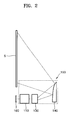
- FIG. 1 is a schematic illustration of a conventional image display apparatus.
- the optical projection system 20 in order to increase the viewing angle of a bundle of light rays generated by an optical projection system 20, the optical projection system 20 is arranged so that the light rays are incident on a lower portion of a screen 40 at an oblique angle.
- An image produced by an optical engine 10 is enlarged and projected by the optical projection system 20 and is incident on a reflective mirror 30. The image reflected from the reflective mirror 30 is projected onto the screen 40.
- the present invention provide a slim optical projection system for an image display apparatus that can project an image at a wide viewing angle and provide improved image quality by correcting distortions caused by the wide viewing angle projection.
- an optical projection system comprises optical means arranged to receive a first image and to produce from said first image a second image and a reflector arranged to reflect the second image, wherein said optical means is configured to generate first distortions in the second image to compensate for second distortions resulting from the reflection of the second image by said reflector.
- a reflector permits an image display apparatus comprising the optical projection system to be of a slim design, while the compensation of the second distortions arising from the use of the reflector can ensure that a high quality image having a wide viewing angle is produced.
- an optical projection system includes a relay lens group to produce an intermediate image from an image created by a display and to generate a first distortion in the intermediate image, a projection lens group to enlarge and project the intermediate image that passes through the relay lens group and to generate a second distortion in the projected image, and a reflector to reflect the image enlarged by the projection lens group to a screen at a wide viewing angle.
- the first and second distortions are used to compensate for a third distortion caused by the reflector.
- the reflector may be an aspherical mirror and have a negative refractive power.
- the optical projection system may further include first and second optical path changers to change optical paths between the relay lens group and the projection lens group and between the projection lens group and the reflector, respectively. While an optical axis of the display can be coaxial with optical axes of the relay lens group and the projection lens group, an optical axis of the reflector is offset from the optical axis of the display.
- the first and second distortions may be spool distortions and the third distortion caused by the reflector may be a barrel distortion.
- an optical projection system includes a refractive optical system to enlarge and transmit an image produced by a display, a reflective optical system to reflect the image transmitted by the refractive optical system at a wide viewing angle, and a relay lens group disposed between the display and the reflective optical system to preliminarily induce a first distortion to compensate for a third distortion caused by the reflective optical system.
- the refractive optical system may preliminarily induce a second distortion that is used in combination with the first distortion to compensate for the third distortion caused by the reflective optical system.
- an image display apparatus includes a display to receive a beam emitted by a light source and to produce an image by processing the received beam according to an input image signal and an optical projection system to enlarge and project the image onto a screen.
- the optical projection system includes: a relay lens group to produce an intermediate image from the image created by the display and to generate a first distortion in the intermediate image, a projection lens group to enlarge and project the intermediate image that passes through the relay lens group and to generate a second distortion in the projected image, and a reflector to reflect the image enlarged by the projection lens group to the screen at a wide viewing angle.
- the first and second distortions may be used to compensate for a third distortion caused by the reflector.
- the optical projection system of the image displaying apparatus may include a refractive optical system to enlarge and transmit an image produced by a display, a reflective optical system to reflect the image transmitted by the refractive optical system at a wide viewing angle, and a relay lens group disposed between the display and the reflective optical system to preliminarily induce a first distortion to compensate for a third distortion caused by the reflective optical system.
- the refractive optical system may preliminarily induce a second distortion that is used in combination with the first distortion to compensate for the third distortion caused by the reflective optical system.
- an image display apparatus includes an optical projection system 150 comprising a relay lens group 110 to produce an intermediate image from an image created by a display device 100, a projection lens group 130 to enlarge and project the intermediate image that produced by the relay lens group 110, and a reflector 140 to enlarge and reflect the image received from the projection lens group 130 onto a screen S.
- an optical projection system 150 comprising a relay lens group 110 to produce an intermediate image from an image created by a display device 100, a projection lens group 130 to enlarge and project the intermediate image that produced by the relay lens group 110, and a reflector 140 to enlarge and reflect the image received from the projection lens group 130 onto a screen S.
- the display device 100 produces an image by modulating a received beam according to image information received from an image information input (not shown).
- suitable display devices 100 include a digital micromirror device (DMD) display, a liquid crystal display (LCD), a grating light valve (GLV) display or a liquid crystal on silicon (LCOS) display.
- DMD digital micromirror device
- LCD liquid crystal display
- GLV grating light valve
- LCOS liquid crystal on silicon
- a DMD display is a two-dimensional array of micromirrors that spatially modulate the intensity of light incident thereon in order to produce an image.
- Figure 3 illustrates an arrangement of optical elements in the optical projection system 150 according to an embodiment of the invention.
- the optical projection system 150 includes a total reflection prism 105 that is disposed between the display device 100 and the relay lens group 110 and allows a beam to be incident on the display device 100 and reflects the image produced by the display device 100 to the relay lens group 110.
- the projection lens group 130 enlarges and projects the intermediate image produced by the relay lens group 110 onto the reflector 140.
- the reflector 140 further enlarges the image received from the projection lens group 130 and projects the enlarged image onto the screen S.
- the reflector 140 may be a flat mirror or an aspherical mirror made of a reflective material, such as plastic, having a negative refractive power so as to diffuse and enlarge the image received from the projection lens group 130. Since image is enlarged and projected by both the projection lens group 130 and the reflector 140, an image having an ultra-wide viewing angle can be produced.
- the relay lens group 110 includes at least one lens and generates a first distortion in the intermediate image.
- the projection lens group 130 also includes at least one lens and generates a second distortion in the intermediate image received from the relay lens group 110.
- the relay lens group 110 and projection lens group 130 are configured so that the combination of the first and second distortions compensates for a third distortion of the image, which is caused by its reflection by the reflector 140. In other words, a predistortion is induced by the relay lens group 110 and the projection lens group 130 to offset a subsequent distortion caused by the reflector 140.
- the optical axes of the relay lens group 110 and the projection lens group 130 are coaxial with an optical axis of the display device 100, while an optical axis of the reflector 140 is offset from the optical axis of the display device 100.
- the reflector 140 causes a barrel distortion in the image.
- the relay lens group 110 and the projection lens group 130 produce spool distortions.
- the image reflected from the reflector 140 onto the screen S has a high visual quality and little distortion.
- the optical projection system 150 includes a refractive optical system, such as the projection lens group 130, and a reflective optical system, such as the reflector 140, and induces the first and second distortions, respectively generated by the relay lens group 110 and the projection lens group 130, to correct the third distortion, which is caused by the reflective optical system.
- a refractive optical system such as the projection lens group 130
- a reflective optical system such as the reflector 140
- the optical projection system 150 can produce images having a wide viewing angle, while permitting the image display apparatus to be of a slim design.
- the optical projection system 150 may further include at least one optical path changer, disposed in an optical path of light exiting the display device 100, to bend the optical path.
- the optical path changer may be a mirror member, reflector, a refractor or a total reflection prism.
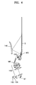
- Figure 4 illustrates an optical projection system according to another embodiment of the invention, in which the optical projection system further includes a first optical path changer M1 disposed within the relay lens group 110, a second optical path changer M2 disposed between the relay lens group 110 and the projection lens group 130, and a third optical path changer M3 disposed between the projection lens group 130 and the reflector 140.
- the first, second, and third optical path changers M1, M2, and M3 may be arranged in a variety of different manners according to structure and size of the image display apparatus, as long as propagation of light is not impeded.
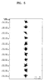
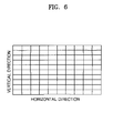
- Figures 5 and 6 illustrate a distribution of light spots at given field positions and image distortions exhibited by an image display apparatus according to an embodiment of the invention.
- image display apparatuses according to various embodiments of the invention exhibit good image quality.
- the use of refractive and reflective optical systems efficiently achieve a wide viewing angle, thereby providing the image display apparatus with a reduced thickness compared to a thickness of a conventional image display apparatus having a screen of comparable size.
- optical projection systems and image display apparatuses include refractive and reflective optical systems to project an image produced by a display onto a screen with a wide viewing angle, thereby reducing a thickness of the image display apparatus.
- the optical projection system and the image display apparatus also generate predistortions, through a relay lens group and/or the refractive optical system, to compensate for distortion caused by the reflective optical system, thereby providing high quality images.
Applications Claiming Priority (1)
| Application Number | Priority Date | Filing Date | Title |
|---|---|---|---|
| KR1020040077374A KR100677134B1 (ko) | 2004-09-24 | 2004-09-24 | 박형 투사 광학계 및 이를 채용한 화상 표시 장치 |
Publications (3)
| Publication Number | Publication Date |
|---|---|
| EP1640783A2 true EP1640783A2 (fr) | 2006-03-29 |
| EP1640783A3 EP1640783A3 (fr) | 2006-07-12 |
| EP1640783B1 EP1640783B1 (fr) | 2008-03-19 |
Family
ID=36098600
Family Applications (1)
| Application Number | Title | Priority Date | Filing Date |
|---|---|---|---|
| EP05108540A Expired - Fee Related EP1640783B1 (fr) | 2004-09-24 | 2005-09-16 | Système de projection optique pour un dispositif d'affichage d'images |
Country Status (6)
| Country | Link |
|---|---|
| US (1) | US7448756B2 (fr) |
| EP (1) | EP1640783B1 (fr) |
| JP (1) | JP2006091867A (fr) |
| KR (1) | KR100677134B1 (fr) |
| CN (1) | CN100381867C (fr) |
| DE (1) | DE602005005410D1 (fr) |
Cited By (1)
| Publication number | Priority date | Publication date | Assignee | Title |
|---|---|---|---|---|
| EP2730961A4 (fr) * | 2011-07-05 | 2015-07-15 | Nittoh Kogaku Kk | Ensemble optique de projection et dispositif projecteur |
Families Citing this family (17)
| Publication number | Priority date | Publication date | Assignee | Title |
|---|---|---|---|---|
| JP4910384B2 (ja) * | 2005-12-16 | 2012-04-04 | 株式会社日立製作所 | 自由曲面光学素子およびそれを含む投射光学ユニットまたは投射型画像表示装置 |
| DE102006008589A1 (de) * | 2006-02-24 | 2007-09-06 | Carl Zeiss Jena Gmbh | Anordnung zur Bilddarstellung in einem Rückprojektions-Fernsehgerät |
| US7959302B2 (en) * | 2006-03-28 | 2011-06-14 | Seiko Epson Corporation | Display device and game machine |
| US8319832B2 (en) * | 2008-01-31 | 2012-11-27 | Denso Corporation | Input apparatus and imaging apparatus |
| US9244287B2 (en) * | 2008-05-09 | 2016-01-26 | Reald Inc. | Optical systems with compact back focal lengths |
| JP2010014815A (ja) | 2008-07-01 | 2010-01-21 | Mitsubishi Electric Corp | 投写型表示装置 |
| JP5106309B2 (ja) | 2008-08-07 | 2012-12-26 | 三菱電機株式会社 | 投写型表示装置 |
| JP5484098B2 (ja) * | 2009-03-18 | 2014-05-07 | 三菱電機株式会社 | 投写光学系及び画像表示装置 |
| US8279527B2 (en) * | 2009-06-16 | 2012-10-02 | Delta Electronics, Inc. | Wide-angle projection optical system |
| KR20110120590A (ko) * | 2010-04-29 | 2011-11-04 | 삼성전자주식회사 | 광학 시스템 및 이를 적용한 영상투사장치 |
| JP5621583B2 (ja) * | 2010-12-27 | 2014-11-12 | 株式会社リコー | 投射光学系及び画像投射装置 |
| JP5163794B2 (ja) * | 2011-09-20 | 2013-03-13 | 株式会社日立製作所 | 投射型画像表示装置 |
| CN103293642B (zh) * | 2012-03-02 | 2015-08-26 | 扬明光学股份有限公司 | 投影镜头和投影装置 |
| WO2014103324A1 (fr) * | 2012-12-28 | 2014-07-03 | 日東光学株式会社 | Système optique de projection et dispositif de projection |
| JP6736366B2 (ja) * | 2015-06-19 | 2020-08-05 | キヤノン株式会社 | 結像光学系、光学機器および画像投射装置 |
| JP6847003B2 (ja) * | 2017-08-17 | 2021-03-24 | 富士フイルム株式会社 | 投写用光学系及び投写型表示装置 |
| TWI831849B (zh) | 2018-12-07 | 2024-02-11 | 日商索尼股份有限公司 | 圖像顯示裝置及投射光學系統 |
Citations (5)
| Publication number | Priority date | Publication date | Assignee | Title |
|---|---|---|---|---|
| WO1998008141A1 (fr) * | 1996-08-23 | 1998-02-26 | Robin Christopher Colclough | Appareil de projection d'images |
| US20010050758A1 (en) * | 2000-05-10 | 2001-12-13 | Hiroshi Suzuki | Image display device and adjustment for alignment |
| US20040032653A1 (en) * | 2002-08-16 | 2004-02-19 | Gohman Jeffrey Alan | Wide angle lens system having a distorted intermediate image |
| US20040156117A1 (en) * | 2003-02-06 | 2004-08-12 | Atsushi Takaura | Projection optical system, magnification projection optical system, magnification projection apparatus, and image projection apparatus |
| US20050174545A1 (en) * | 2004-02-09 | 2005-08-11 | Jong-Soo Lee | Optical projection system and image display device having the same |
Family Cites Families (17)
| Publication number | Priority date | Publication date | Assignee | Title |
|---|---|---|---|---|
| US5274406A (en) * | 1987-12-29 | 1993-12-28 | Asahi Kogaku Kogyo Kabushiki Kaisha | Image projecting device |
| US5692820A (en) * | 1992-02-20 | 1997-12-02 | Kopin Corporation | Projection monitor |
| US5625495A (en) * | 1994-12-07 | 1997-04-29 | U.S. Precision Lens Inc. | Telecentric lens systems for forming an image of an object composed of pixels |
| JPH09138349A (ja) * | 1995-09-11 | 1997-05-27 | Semiconductor Energy Lab Co Ltd | 表示装置 |
| KR100471458B1 (ko) | 1997-03-29 | 2005-06-28 | 엘지전자 주식회사 | 액정프로젝션tv용렌즈 |
| KR200156536Y1 (ko) | 1997-06-02 | 1999-09-01 | 김영환 | 리어 프로젝션 텔레비젼의 프로젝터 |
| JP4240342B2 (ja) | 1998-03-20 | 2009-03-18 | フジノン株式会社 | レトロフォーカス型レンズ |
| JPH11305337A (ja) * | 1998-04-17 | 1999-11-05 | Seiko Epson Corp | 背面投写型表示装置 |
| JP2000250131A (ja) * | 1999-03-01 | 2000-09-14 | Lg Electronics Inc | 投写形ディスプレイ |
| JP2003503744A (ja) | 1999-06-28 | 2003-01-28 | コーニンクレッカ フィリップス エレクトロニクス エヌ ヴィ | トンネルプリズムが設けられたインテグレータ装置を具える投写形表示装置 |
| KR100534574B1 (ko) | 2001-04-24 | 2005-12-07 | 삼성에스디아이 주식회사 | 프로젝션 시스템 및 그 프로젝션방법 |
| KR100410964B1 (ko) | 2001-07-27 | 2003-12-18 | 삼성전기주식회사 | 프로젝션 디스플레이 장치의 프로젝션 렌즈 |
| US7714943B2 (en) * | 2002-06-12 | 2010-05-11 | Geo Semiconductor Inc. | Ultra-thin image projection system |
| JP3951833B2 (ja) * | 2002-06-28 | 2007-08-01 | 日本ビクター株式会社 | 資料提示装置 |
| US7090354B2 (en) * | 2002-08-16 | 2006-08-15 | Infocus Corporation | Projection device and screen |
| JP4186591B2 (ja) * | 2002-11-01 | 2008-11-26 | 日本ビクター株式会社 | 結像光学系及び資料提示装置 |
| JP4086686B2 (ja) * | 2003-03-18 | 2008-05-14 | キヤノン株式会社 | 投射光学系、投射型画像表示装置および画像表示システム |
-
2004
- 2004-09-24 KR KR1020040077374A patent/KR100677134B1/ko not_active IP Right Cessation
-
2005
- 2005-09-01 JP JP2005253449A patent/JP2006091867A/ja active Pending
- 2005-09-16 EP EP05108540A patent/EP1640783B1/fr not_active Expired - Fee Related
- 2005-09-16 DE DE602005005410T patent/DE602005005410D1/de active Active
- 2005-09-19 CN CNB2005101048117A patent/CN100381867C/zh not_active Expired - Fee Related
- 2005-09-22 US US11/231,885 patent/US7448756B2/en not_active Expired - Fee Related
Patent Citations (5)
| Publication number | Priority date | Publication date | Assignee | Title |
|---|---|---|---|---|
| WO1998008141A1 (fr) * | 1996-08-23 | 1998-02-26 | Robin Christopher Colclough | Appareil de projection d'images |
| US20010050758A1 (en) * | 2000-05-10 | 2001-12-13 | Hiroshi Suzuki | Image display device and adjustment for alignment |
| US20040032653A1 (en) * | 2002-08-16 | 2004-02-19 | Gohman Jeffrey Alan | Wide angle lens system having a distorted intermediate image |
| US20040156117A1 (en) * | 2003-02-06 | 2004-08-12 | Atsushi Takaura | Projection optical system, magnification projection optical system, magnification projection apparatus, and image projection apparatus |
| US20050174545A1 (en) * | 2004-02-09 | 2005-08-11 | Jong-Soo Lee | Optical projection system and image display device having the same |
Non-Patent Citations (2)
| Title |
|---|
| PATENT ABSTRACTS OF JAPAN vol. 1997, no. 09, 30 September 1997 (1997-09-30) -& JP 09 138349 A (SEMICONDUCTOR ENERGY LAB CO LTD), 27 May 1997 (1997-05-27) * |
| PATENT ABSTRACTS OF JAPAN vol. 2000, no. 12, 3 January 2001 (2001-01-03) -& JP 2000 250131 A (LG ELECTRONICS INC), 14 September 2000 (2000-09-14) * |
Cited By (4)
| Publication number | Priority date | Publication date | Assignee | Title |
|---|---|---|---|---|
| EP2730961A4 (fr) * | 2011-07-05 | 2015-07-15 | Nittoh Kogaku Kk | Ensemble optique de projection et dispositif projecteur |
| US9372388B2 (en) | 2011-07-05 | 2016-06-21 | Nittoh Kogaku K.K. | Projection optical assembly with multiple refractive optical systems and related projector device |
| US10310366B2 (en) | 2011-07-05 | 2019-06-04 | Nittoh Inc. | Projection optical assembly and projector device |
| US10754239B2 (en) | 2011-07-05 | 2020-08-25 | Nittoh Inc. | Projection optical assembly and projector device |
Also Published As
| Publication number | Publication date |
|---|---|
| EP1640783B1 (fr) | 2008-03-19 |
| US7448756B2 (en) | 2008-11-11 |
| KR20060028278A (ko) | 2006-03-29 |
| EP1640783A3 (fr) | 2006-07-12 |
| KR100677134B1 (ko) | 2007-02-02 |
| DE602005005410D1 (de) | 2008-04-30 |
| JP2006091867A (ja) | 2006-04-06 |
| CN100381867C (zh) | 2008-04-16 |
| CN1752798A (zh) | 2006-03-29 |
| US20060066760A1 (en) | 2006-03-30 |
Similar Documents
| Publication | Publication Date | Title |
|---|---|---|
| EP1640783B1 (fr) | Système de projection optique pour un dispositif d'affichage d'images | |
| EP1965254B1 (fr) | Appareil d'affichage de type projection | |
| US9983394B2 (en) | Projection optical system and image display apparatus | |
| US6715885B2 (en) | Display device with screen having curved surface | |
| US7009765B2 (en) | Wide angle lens system having a distorted intermediate image | |
| US6752500B1 (en) | Rear surface projection type display device | |
| US7959305B2 (en) | Light recycling in a micromirror-based projection display system | |
| US7789516B2 (en) | Projection type image display device | |
| US6406150B1 (en) | Compact rear projections system | |
| JP3429291B2 (ja) | プロジェクションディスプレイ装置のプロジェクションレンズ | |
| US8901473B2 (en) | Projection optical system having an aperture to limit quantity of light to a refractive optical system, and image display device using the same | |
| EP2410378A1 (fr) | Système optique de projection et dispositif de projection d'image | |
| US20090021703A1 (en) | Projection optical system, magnification projection optical system, magnification projection apparatus, and image projection apparatus | |
| JPH07168123A (ja) | カラー映像の投写装置およびその装置に用いられる変換用光学システム | |
| EP1802113A1 (fr) | Système de rétroéclairage pour un écran d'affichage à cristaux liquides et dispositif d'affichage correspondant | |
| CN109870791B (zh) | 短焦图像投影装置 | |
| CN111208701A (zh) | 激光投影设备 | |
| JP2004279988A (ja) | 投射光学系 | |
| JP2004177654A (ja) | 投写型画像表示装置 | |
| CN110456600B (zh) | 投影镜头及激光投影装置 | |
| CN110456599B (zh) | 投影成像系统及激光投影装置 | |
| Ley et al. | Imaging and non-imaging illumination of DLP for high resolution headlamps | |
| US20220299790A1 (en) | Projector and projection method | |
| CN112578610B (zh) | 投影镜头及激光投影设备 | |
| CA2305268C (fr) | Appareil et technique de projection optique |
Legal Events
| Date | Code | Title | Description |
|---|---|---|---|
| PUAI | Public reference made under article 153(3) epc to a published international application that has entered the european phase |
Free format text: ORIGINAL CODE: 0009012 |
|
| AK | Designated contracting states |
Kind code of ref document: A2 Designated state(s): AT BE BG CH CY CZ DE DK EE ES FI FR GB GR HU IE IS IT LI LT LU LV MC NL PL PT RO SE SI SK TR |
|
| AX | Request for extension of the european patent |
Extension state: AL BA HR MK YU |
|
| PUAL | Search report despatched |
Free format text: ORIGINAL CODE: 0009013 |
|
| AK | Designated contracting states |
Kind code of ref document: A3 Designated state(s): AT BE BG CH CY CZ DE DK EE ES FI FR GB GR HU IE IS IT LI LT LU LV MC NL PL PT RO SE SI SK TR |
|
| AX | Request for extension of the european patent |
Extension state: AL BA HR MK YU |
|
| RIC1 | Information provided on ipc code assigned before grant |
Ipc: G02B 17/08 20060101ALI20060606BHEP Ipc: G03B 21/28 20060101ALI20060606BHEP Ipc: H04N 5/74 20060101ALI20060606BHEP Ipc: H04N 9/31 20060101ALI20060606BHEP Ipc: G02B 27/18 20060101AFI20051222BHEP |
|
| 17P | Request for examination filed |
Effective date: 20070108 |
|
| R17C | First examination report despatched (corrected) |
Effective date: 20070208 |
|
| AKX | Designation fees paid |
Designated state(s): DE FR GB IT NL |
|
| GRAP | Despatch of communication of intention to grant a patent |
Free format text: ORIGINAL CODE: EPIDOSNIGR1 |
|
| GRAS | Grant fee paid |
Free format text: ORIGINAL CODE: EPIDOSNIGR3 |
|
| GRAA | (expected) grant |
Free format text: ORIGINAL CODE: 0009210 |
|
| AK | Designated contracting states |
Kind code of ref document: B1 Designated state(s): DE FR GB IT NL |
|
| REG | Reference to a national code |
Ref country code: GB Ref legal event code: FG4D |
|
| REF | Corresponds to: |
Ref document number: 602005005410 Country of ref document: DE Date of ref document: 20080430 Kind code of ref document: P |
|
| NLV1 | Nl: lapsed or annulled due to failure to fulfill the requirements of art. 29p and 29m of the patents act | ||
| PG25 | Lapsed in a contracting state [announced via postgrant information from national office to epo] |
Ref country code: NL Free format text: LAPSE BECAUSE OF FAILURE TO SUBMIT A TRANSLATION OF THE DESCRIPTION OR TO PAY THE FEE WITHIN THE PRESCRIBED TIME-LIMIT Effective date: 20080319 |
|
| EN | Fr: translation not filed | ||
| PLBE | No opposition filed within time limit |
Free format text: ORIGINAL CODE: 0009261 |
|
| STAA | Information on the status of an ep patent application or granted ep patent |
Free format text: STATUS: NO OPPOSITION FILED WITHIN TIME LIMIT |
|
| PG25 | Lapsed in a contracting state [announced via postgrant information from national office to epo] |
Ref country code: DE Free format text: LAPSE BECAUSE OF FAILURE TO SUBMIT A TRANSLATION OF THE DESCRIPTION OR TO PAY THE FEE WITHIN THE PRESCRIBED TIME-LIMIT Effective date: 20080620 |
|
| 26N | No opposition filed |
Effective date: 20081222 |
|
| PG25 | Lapsed in a contracting state [announced via postgrant information from national office to epo] |
Ref country code: IT Free format text: LAPSE BECAUSE OF FAILURE TO SUBMIT A TRANSLATION OF THE DESCRIPTION OR TO PAY THE FEE WITHIN THE PRESCRIBED TIME-LIMIT Effective date: 20080319 |
|
| PG25 | Lapsed in a contracting state [announced via postgrant information from national office to epo] |
Ref country code: FR Free format text: LAPSE BECAUSE OF FAILURE TO SUBMIT A TRANSLATION OF THE DESCRIPTION OR TO PAY THE FEE WITHIN THE PRESCRIBED TIME-LIMIT Effective date: 20090109 |
|
| PGFP | Annual fee paid to national office [announced via postgrant information from national office to epo] |
Ref country code: GB Payment date: 20130905 Year of fee payment: 9 |
|
| GBPC | Gb: european patent ceased through non-payment of renewal fee |
Effective date: 20140916 |
|
| PG25 | Lapsed in a contracting state [announced via postgrant information from national office to epo] |
Ref country code: GB Free format text: LAPSE BECAUSE OF NON-PAYMENT OF DUE FEES Effective date: 20140916 |