EP1640783A2 - Optical projection system for an image display apparatus - Google Patents
Optical projection system for an image display apparatus Download PDFInfo
- Publication number
- EP1640783A2 EP1640783A2 EP05108540A EP05108540A EP1640783A2 EP 1640783 A2 EP1640783 A2 EP 1640783A2 EP 05108540 A EP05108540 A EP 05108540A EP 05108540 A EP05108540 A EP 05108540A EP 1640783 A2 EP1640783 A2 EP 1640783A2
- Authority
- EP
- European Patent Office
- Prior art keywords
- image
- optical
- distortion
- lens group
- projection system
- Prior art date
- Legal status (The legal status is an assumption and is not a legal conclusion. Google has not performed a legal analysis and makes no representation as to the accuracy of the status listed.)
- Granted
Links
Images


Classifications
-
- G—PHYSICS
- G02—OPTICS
- G02B—OPTICAL ELEMENTS, SYSTEMS OR APPARATUS
- G02B27/00—Optical systems or apparatus not provided for by any of the groups G02B1/00 - G02B26/00, G02B30/00
- G02B27/18—Optical systems or apparatus not provided for by any of the groups G02B1/00 - G02B26/00, G02B30/00 for optical projection, e.g. combination of mirror and condenser and objective
-
- G—PHYSICS
- G02—OPTICS
- G02B—OPTICAL ELEMENTS, SYSTEMS OR APPARATUS
- G02B17/00—Systems with reflecting surfaces, with or without refracting elements
- G02B17/08—Catadioptric systems
-
- G—PHYSICS
- G02—OPTICS
- G02B—OPTICAL ELEMENTS, SYSTEMS OR APPARATUS
- G02B17/00—Systems with reflecting surfaces, with or without refracting elements
- G02B17/08—Catadioptric systems
- G02B17/0852—Catadioptric systems having a field corrector only
-
- G—PHYSICS
- G02—OPTICS
- G02B—OPTICAL ELEMENTS, SYSTEMS OR APPARATUS
- G02B27/00—Optical systems or apparatus not provided for by any of the groups G02B1/00 - G02B26/00, G02B30/00
- G02B27/0025—Optical systems or apparatus not provided for by any of the groups G02B1/00 - G02B26/00, G02B30/00 for optical correction, e.g. distorsion, aberration
-
- G—PHYSICS
- G02—OPTICS
- G02B—OPTICAL ELEMENTS, SYSTEMS OR APPARATUS
- G02B27/00—Optical systems or apparatus not provided for by any of the groups G02B1/00 - G02B26/00, G02B30/00
- G02B27/28—Optical systems or apparatus not provided for by any of the groups G02B1/00 - G02B26/00, G02B30/00 for polarising
-
- G—PHYSICS
- G03—PHOTOGRAPHY; CINEMATOGRAPHY; ANALOGOUS TECHNIQUES USING WAVES OTHER THAN OPTICAL WAVES; ELECTROGRAPHY; HOLOGRAPHY
- G03B—APPARATUS OR ARRANGEMENTS FOR TAKING PHOTOGRAPHS OR FOR PROJECTING OR VIEWING THEM; APPARATUS OR ARRANGEMENTS EMPLOYING ANALOGOUS TECHNIQUES USING WAVES OTHER THAN OPTICAL WAVES; ACCESSORIES THEREFOR
- G03B21/00—Projectors or projection-type viewers; Accessories therefor
- G03B21/10—Projectors with built-in or built-on screen
-
- G—PHYSICS
- G03—PHOTOGRAPHY; CINEMATOGRAPHY; ANALOGOUS TECHNIQUES USING WAVES OTHER THAN OPTICAL WAVES; ELECTROGRAPHY; HOLOGRAPHY
- G03B—APPARATUS OR ARRANGEMENTS FOR TAKING PHOTOGRAPHS OR FOR PROJECTING OR VIEWING THEM; APPARATUS OR ARRANGEMENTS EMPLOYING ANALOGOUS TECHNIQUES USING WAVES OTHER THAN OPTICAL WAVES; ACCESSORIES THEREFOR
- G03B21/00—Projectors or projection-type viewers; Accessories therefor
- G03B21/14—Details
- G03B21/28—Reflectors in projection beam
-
- G—PHYSICS
- G03—PHOTOGRAPHY; CINEMATOGRAPHY; ANALOGOUS TECHNIQUES USING WAVES OTHER THAN OPTICAL WAVES; ELECTROGRAPHY; HOLOGRAPHY
- G03B—APPARATUS OR ARRANGEMENTS FOR TAKING PHOTOGRAPHS OR FOR PROJECTING OR VIEWING THEM; APPARATUS OR ARRANGEMENTS EMPLOYING ANALOGOUS TECHNIQUES USING WAVES OTHER THAN OPTICAL WAVES; ACCESSORIES THEREFOR
- G03B21/00—Projectors or projection-type viewers; Accessories therefor
- G03B21/54—Accessories
- G03B21/56—Projection screens
-
- H—ELECTRICITY
- H04—ELECTRIC COMMUNICATION TECHNIQUE
- H04N—PICTORIAL COMMUNICATION, e.g. TELEVISION
- H04N5/00—Details of television systems
- H04N5/74—Projection arrangements for image reproduction, e.g. using eidophor
-
- H—ELECTRICITY
- H04—ELECTRIC COMMUNICATION TECHNIQUE
- H04N—PICTORIAL COMMUNICATION, e.g. TELEVISION
- H04N9/00—Details of colour television systems
- H04N9/12—Picture reproducers
- H04N9/31—Projection devices for colour picture display, e.g. using electronic spatial light modulators [ESLM]
- H04N9/3141—Constructional details thereof
-
- H—ELECTRICITY
- H04—ELECTRIC COMMUNICATION TECHNIQUE
- H04N—PICTORIAL COMMUNICATION, e.g. TELEVISION
- H04N5/00—Details of television systems
- H04N5/74—Projection arrangements for image reproduction, e.g. using eidophor
- H04N5/7416—Projection arrangements for image reproduction, e.g. using eidophor involving the use of a spatial light modulator, e.g. a light valve, controlled by a video signal
Definitions
- the invention relates to an optical projection system and, more particularly, to an optical projection system that projects an image produced by a display onto a screen with a wide viewing angle and provides improved image quality by correcting distortions caused by the wide viewing angle projection and an image display apparatus employing the same.
- An image display apparatus includes a display, which controls a light source to provide illumination for a plurality of pixels to create a color image, and an optical projection system that enlarges and projects the color image onto a screen.
- a display which controls a light source to provide illumination for a plurality of pixels to create a color image
- an optical projection system that enlarges and projects the color image onto a screen.
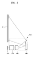
- FIG. 1 is a schematic illustration of a conventional image display apparatus.
- the optical projection system 20 in order to increase the viewing angle of a bundle of light rays generated by an optical projection system 20, the optical projection system 20 is arranged so that the light rays are incident on a lower portion of a screen 40 at an oblique angle.
- An image produced by an optical engine 10 is enlarged and projected by the optical projection system 20 and is incident on a reflective mirror 30. The image reflected from the reflective mirror 30 is projected onto the screen 40.
- the present invention provide a slim optical projection system for an image display apparatus that can project an image at a wide viewing angle and provide improved image quality by correcting distortions caused by the wide viewing angle projection.
- an optical projection system comprises optical means arranged to receive a first image and to produce from said first image a second image and a reflector arranged to reflect the second image, wherein said optical means is configured to generate first distortions in the second image to compensate for second distortions resulting from the reflection of the second image by said reflector.
- a reflector permits an image display apparatus comprising the optical projection system to be of a slim design, while the compensation of the second distortions arising from the use of the reflector can ensure that a high quality image having a wide viewing angle is produced.
- an optical projection system includes a relay lens group to produce an intermediate image from an image created by a display and to generate a first distortion in the intermediate image, a projection lens group to enlarge and project the intermediate image that passes through the relay lens group and to generate a second distortion in the projected image, and a reflector to reflect the image enlarged by the projection lens group to a screen at a wide viewing angle.
- the first and second distortions are used to compensate for a third distortion caused by the reflector.
- the reflector may be an aspherical mirror and have a negative refractive power.
- the optical projection system may further include first and second optical path changers to change optical paths between the relay lens group and the projection lens group and between the projection lens group and the reflector, respectively. While an optical axis of the display can be coaxial with optical axes of the relay lens group and the projection lens group, an optical axis of the reflector is offset from the optical axis of the display.
- the first and second distortions may be spool distortions and the third distortion caused by the reflector may be a barrel distortion.
- an optical projection system includes a refractive optical system to enlarge and transmit an image produced by a display, a reflective optical system to reflect the image transmitted by the refractive optical system at a wide viewing angle, and a relay lens group disposed between the display and the reflective optical system to preliminarily induce a first distortion to compensate for a third distortion caused by the reflective optical system.
- the refractive optical system may preliminarily induce a second distortion that is used in combination with the first distortion to compensate for the third distortion caused by the reflective optical system.
- an image display apparatus includes a display to receive a beam emitted by a light source and to produce an image by processing the received beam according to an input image signal and an optical projection system to enlarge and project the image onto a screen.
- the optical projection system includes: a relay lens group to produce an intermediate image from the image created by the display and to generate a first distortion in the intermediate image, a projection lens group to enlarge and project the intermediate image that passes through the relay lens group and to generate a second distortion in the projected image, and a reflector to reflect the image enlarged by the projection lens group to the screen at a wide viewing angle.
- the first and second distortions may be used to compensate for a third distortion caused by the reflector.
- the optical projection system of the image displaying apparatus may include a refractive optical system to enlarge and transmit an image produced by a display, a reflective optical system to reflect the image transmitted by the refractive optical system at a wide viewing angle, and a relay lens group disposed between the display and the reflective optical system to preliminarily induce a first distortion to compensate for a third distortion caused by the reflective optical system.
- the refractive optical system may preliminarily induce a second distortion that is used in combination with the first distortion to compensate for the third distortion caused by the reflective optical system.
- an image display apparatus includes an optical projection system 150 comprising a relay lens group 110 to produce an intermediate image from an image created by a display device 100, a projection lens group 130 to enlarge and project the intermediate image that produced by the relay lens group 110, and a reflector 140 to enlarge and reflect the image received from the projection lens group 130 onto a screen S.
- an optical projection system 150 comprising a relay lens group 110 to produce an intermediate image from an image created by a display device 100, a projection lens group 130 to enlarge and project the intermediate image that produced by the relay lens group 110, and a reflector 140 to enlarge and reflect the image received from the projection lens group 130 onto a screen S.
- the display device 100 produces an image by modulating a received beam according to image information received from an image information input (not shown).
- suitable display devices 100 include a digital micromirror device (DMD) display, a liquid crystal display (LCD), a grating light valve (GLV) display or a liquid crystal on silicon (LCOS) display.
- DMD digital micromirror device
- LCD liquid crystal display
- GLV grating light valve
- LCOS liquid crystal on silicon
- a DMD display is a two-dimensional array of micromirrors that spatially modulate the intensity of light incident thereon in order to produce an image.
- Figure 3 illustrates an arrangement of optical elements in the optical projection system 150 according to an embodiment of the invention.
- the optical projection system 150 includes a total reflection prism 105 that is disposed between the display device 100 and the relay lens group 110 and allows a beam to be incident on the display device 100 and reflects the image produced by the display device 100 to the relay lens group 110.
- the projection lens group 130 enlarges and projects the intermediate image produced by the relay lens group 110 onto the reflector 140.
- the reflector 140 further enlarges the image received from the projection lens group 130 and projects the enlarged image onto the screen S.
- the reflector 140 may be a flat mirror or an aspherical mirror made of a reflective material, such as plastic, having a negative refractive power so as to diffuse and enlarge the image received from the projection lens group 130. Since image is enlarged and projected by both the projection lens group 130 and the reflector 140, an image having an ultra-wide viewing angle can be produced.
- the relay lens group 110 includes at least one lens and generates a first distortion in the intermediate image.
- the projection lens group 130 also includes at least one lens and generates a second distortion in the intermediate image received from the relay lens group 110.
- the relay lens group 110 and projection lens group 130 are configured so that the combination of the first and second distortions compensates for a third distortion of the image, which is caused by its reflection by the reflector 140. In other words, a predistortion is induced by the relay lens group 110 and the projection lens group 130 to offset a subsequent distortion caused by the reflector 140.
- the optical axes of the relay lens group 110 and the projection lens group 130 are coaxial with an optical axis of the display device 100, while an optical axis of the reflector 140 is offset from the optical axis of the display device 100.
- the reflector 140 causes a barrel distortion in the image.
- the relay lens group 110 and the projection lens group 130 produce spool distortions.
- the image reflected from the reflector 140 onto the screen S has a high visual quality and little distortion.
- the optical projection system 150 includes a refractive optical system, such as the projection lens group 130, and a reflective optical system, such as the reflector 140, and induces the first and second distortions, respectively generated by the relay lens group 110 and the projection lens group 130, to correct the third distortion, which is caused by the reflective optical system.
- a refractive optical system such as the projection lens group 130
- a reflective optical system such as the reflector 140
- the optical projection system 150 can produce images having a wide viewing angle, while permitting the image display apparatus to be of a slim design.
- the optical projection system 150 may further include at least one optical path changer, disposed in an optical path of light exiting the display device 100, to bend the optical path.
- the optical path changer may be a mirror member, reflector, a refractor or a total reflection prism.
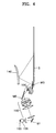
- Figure 4 illustrates an optical projection system according to another embodiment of the invention, in which the optical projection system further includes a first optical path changer M1 disposed within the relay lens group 110, a second optical path changer M2 disposed between the relay lens group 110 and the projection lens group 130, and a third optical path changer M3 disposed between the projection lens group 130 and the reflector 140.
- the first, second, and third optical path changers M1, M2, and M3 may be arranged in a variety of different manners according to structure and size of the image display apparatus, as long as propagation of light is not impeded.
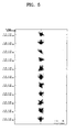
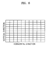
- Figures 5 and 6 illustrate a distribution of light spots at given field positions and image distortions exhibited by an image display apparatus according to an embodiment of the invention.
- image display apparatuses according to various embodiments of the invention exhibit good image quality.
- the use of refractive and reflective optical systems efficiently achieve a wide viewing angle, thereby providing the image display apparatus with a reduced thickness compared to a thickness of a conventional image display apparatus having a screen of comparable size.
- optical projection systems and image display apparatuses include refractive and reflective optical systems to project an image produced by a display onto a screen with a wide viewing angle, thereby reducing a thickness of the image display apparatus.
- the optical projection system and the image display apparatus also generate predistortions, through a relay lens group and/or the refractive optical system, to compensate for distortion caused by the reflective optical system, thereby providing high quality images.
Landscapes
- Physics & Mathematics (AREA)
- General Physics & Mathematics (AREA)
- Optics & Photonics (AREA)
- Engineering & Computer Science (AREA)
- Multimedia (AREA)
- Signal Processing (AREA)
- Lenses (AREA)
- Projection Apparatus (AREA)
- Transforming Electric Information Into Light Information (AREA)
Abstract
Description
- The invention relates to an optical projection system and, more particularly, to an optical projection system that projects an image produced by a display onto a screen with a wide viewing angle and provides improved image quality by correcting distortions caused by the wide viewing angle projection and an image display apparatus employing the same.
- An image display apparatus includes a display, which controls a light source to provide illumination for a plurality of pixels to create a color image, and an optical projection system that enlarges and projects the color image onto a screen. In response to an increasing demand, research has been conducted with the aim of providing an image display apparatus having a large screen, high resolution and a relatively slim configuration.
- In order to enable an image display apparatus to have a slim configuration, the optical projection system generates a bundle of light rays at a wide viewing angle. However, when the optical projection system is located at a center of the screen, the viewing angle of the bundle of projected light rays generated by the optical projection system can only be increased to by a limited amount. Figure 1 is a schematic illustration of a conventional image display apparatus. Referring to Figure 1, in order to increase the viewing angle of a bundle of light rays generated by an
optical projection system 20, theoptical projection system 20 is arranged so that the light rays are incident on a lower portion of ascreen 40 at an oblique angle. An image produced by anoptical engine 10 is enlarged and projected by theoptical projection system 20 and is incident on areflective mirror 30. The image reflected from thereflective mirror 30 is projected onto thescreen 40. - When the image that emanates from the
optical projection system 20 is reflected onto thescreen 40 by thereflective mirror 30 as described above, it must be diffused at a very large angle, since the thickness of the image display apparatus is small. However, a portion of the image that is projected at a wide angle by theoptical projection system 20 onto the lower portion of thescreen 40 tends to undergo distortion, which can degrade the image quality. Thus, it is technically difficult to provide an image display apparatus with a large screen and a high image quality that has a slim design. - The present invention provide a slim optical projection system for an image display apparatus that can project an image at a wide viewing angle and provide improved image quality by correcting distortions caused by the wide viewing angle projection.
- According to a first aspect of the invention, an optical projection system comprises optical means arranged to receive a first image and to produce from said first image a second image and a reflector arranged to reflect the second image, wherein said optical means is configured to generate first distortions in the second image to compensate for second distortions resulting from the reflection of the second image by said reflector.
- The use of a reflector permits an image display apparatus comprising the optical projection system to be of a slim design, while the compensation of the second distortions arising from the use of the reflector can ensure that a high quality image having a wide viewing angle is produced.
- This aspect also provides an image display apparatus comprising such an optical projection system and image creation means arranged to generate said first image. According to a second aspect of the invention, an optical projection system includes a relay lens group to produce an intermediate image from an image created by a display and to generate a first distortion in the intermediate image, a projection lens group to enlarge and project the intermediate image that passes through the relay lens group and to generate a second distortion in the projected image, and a reflector to reflect the image enlarged by the projection lens group to a screen at a wide viewing angle. The first and second distortions are used to compensate for a third distortion caused by the reflector.
- The reflector may be an aspherical mirror and have a negative refractive power.
- The optical projection system may further include first and second optical path changers to change optical paths between the relay lens group and the projection lens group and between the projection lens group and the reflector, respectively. While an optical axis of the display can be coaxial with optical axes of the relay lens group and the projection lens group, an optical axis of the reflector is offset from the optical axis of the display. The first and second distortions may be spool distortions and the third distortion caused by the reflector may be a barrel distortion.
- According to a third aspect of the invention, an optical projection system includes a refractive optical system to enlarge and transmit an image produced by a display, a reflective optical system to reflect the image transmitted by the refractive optical system at a wide viewing angle, and a relay lens group disposed between the display and the reflective optical system to preliminarily induce a first distortion to compensate for a third distortion caused by the reflective optical system. The refractive optical system may preliminarily induce a second distortion that is used in combination with the first distortion to compensate for the third distortion caused by the reflective optical system.
- According to a fourth aspect of the invention, an image display apparatus includes a display to receive a beam emitted by a light source and to produce an image by processing the received beam according to an input image signal and an optical projection system to enlarge and project the image onto a screen. The optical projection system includes: a relay lens group to produce an intermediate image from the image created by the display and to generate a first distortion in the intermediate image, a projection lens group to enlarge and project the intermediate image that passes through the relay lens group and to generate a second distortion in the projected image, and a reflector to reflect the image enlarged by the projection lens group to the screen at a wide viewing angle. The first and second distortions may be used to compensate for a third distortion caused by the reflector.
- The optical projection system of the image displaying apparatus may include a refractive optical system to enlarge and transmit an image produced by a display, a reflective optical system to reflect the image transmitted by the refractive optical system at a wide viewing angle, and a relay lens group disposed between the display and the reflective optical system to preliminarily induce a first distortion to compensate for a third distortion caused by the reflective optical system. The refractive optical system may preliminarily induce a second distortion that is used in combination with the first distortion to compensate for the third distortion caused by the reflective optical system.
- Embodiments of the invention will now be described with reference to the accompanying drawings, of which:
- Figure 1 schematically illustrates a conventional image display apparatus;
- Figure 2 schematically illustrates an image display apparatus according to an embodiment of the present invention;
- Figure 3 illustrates an optical projection system according to an embodiment of the present invention;
- Figure 4 illustrates an optical projection system according to another embodiment of the present invention;
- Figure 5 illustrates a distribution of light spots for each field position exhibited by an image display apparatus according to an embodiment of the present invention; and
- Figure 6 illustrates distortions of an image exhibited by an image display apparatus according to an embodiment of the present invention.
- In the following description of example embodiments of the invention, reference will be made to the accompanying drawings, in which like reference numerals refer to the like elements throughout.
- Referring to Figure 2, an image display apparatus includes an
optical projection system 150 comprising arelay lens group 110 to produce an intermediate image from an image created by adisplay device 100, aprojection lens group 130 to enlarge and project the intermediate image that produced by therelay lens group 110, and areflector 140 to enlarge and reflect the image received from theprojection lens group 130 onto a screen S. - The
display device 100 produces an image by modulating a received beam according to image information received from an image information input (not shown). Examples ofsuitable display devices 100 include a digital micromirror device (DMD) display, a liquid crystal display (LCD), a grating light valve (GLV) display or a liquid crystal on silicon (LCOS) display. A DMD display is a two-dimensional array of micromirrors that spatially modulate the intensity of light incident thereon in order to produce an image. - Figure 3 illustrates an arrangement of optical elements in the
optical projection system 150 according to an embodiment of the invention. Referring to Figure 3, theoptical projection system 150 includes atotal reflection prism 105 that is disposed between thedisplay device 100 and therelay lens group 110 and allows a beam to be incident on thedisplay device 100 and reflects the image produced by thedisplay device 100 to therelay lens group 110. - The
projection lens group 130 enlarges and projects the intermediate image produced by therelay lens group 110 onto thereflector 140. Thereflector 140 further enlarges the image received from theprojection lens group 130 and projects the enlarged image onto the screen S. Thereflector 140 may be a flat mirror or an aspherical mirror made of a reflective material, such as plastic, having a negative refractive power so as to diffuse and enlarge the image received from theprojection lens group 130. Since image is enlarged and projected by both theprojection lens group 130 and thereflector 140, an image having an ultra-wide viewing angle can be produced. - The
relay lens group 110 includes at least one lens and generates a first distortion in the intermediate image. Theprojection lens group 130 also includes at least one lens and generates a second distortion in the intermediate image received from therelay lens group 110. Therelay lens group 110 andprojection lens group 130 are configured so that the combination of the first and second distortions compensates for a third distortion of the image, which is caused by its reflection by thereflector 140. In other words, a predistortion is induced by therelay lens group 110 and theprojection lens group 130 to offset a subsequent distortion caused by thereflector 140. - In the optical projection system of Figure 3, the optical axes of the
relay lens group 110 and theprojection lens group 130 are coaxial with an optical axis of thedisplay device 100, while an optical axis of thereflector 140 is offset from the optical axis of thedisplay device 100. - In the arrangement of Figure 3, the
reflector 140 causes a barrel distortion in the image. In order to compensate for this barrel distortion, therelay lens group 110 and theprojection lens group 130 produce spool distortions. As a result, the image reflected from thereflector 140 onto the screen S has a high visual quality and little distortion. - In summary, in order to achieve a wide viewing angle, the
optical projection system 150 includes a refractive optical system, such as theprojection lens group 130, and a reflective optical system, such as thereflector 140, and induces the first and second distortions, respectively generated by therelay lens group 110 and theprojection lens group 130, to correct the third distortion, which is caused by the reflective optical system. - Through using the refractive and reflective
optical systems optical projection system 150 can produce images having a wide viewing angle, while permitting the image display apparatus to be of a slim design. - In order to further reduce the thickness of the image display apparatus, the
optical projection system 150 may further include at least one optical path changer, disposed in an optical path of light exiting thedisplay device 100, to bend the optical path. The optical path changer may be a mirror member, reflector, a refractor or a total reflection prism. - Figure 4 illustrates an optical projection system according to another embodiment of the invention, in which the optical projection system further includes a first optical path changer M1 disposed within the
relay lens group 110, a second optical path changer M2 disposed between therelay lens group 110 and theprojection lens group 130, and a third optical path changer M3 disposed between theprojection lens group 130 and thereflector 140. Here, the first, second, and third optical path changers M1, M2, and M3 may be arranged in a variety of different manners according to structure and size of the image display apparatus, as long as propagation of light is not impeded. - Detailed design data of the optical projection system according to various embodiments of the invention is as follows. It should be understood that this detailed design data is merely exemplary and is not intended to limit the scope of the invention.


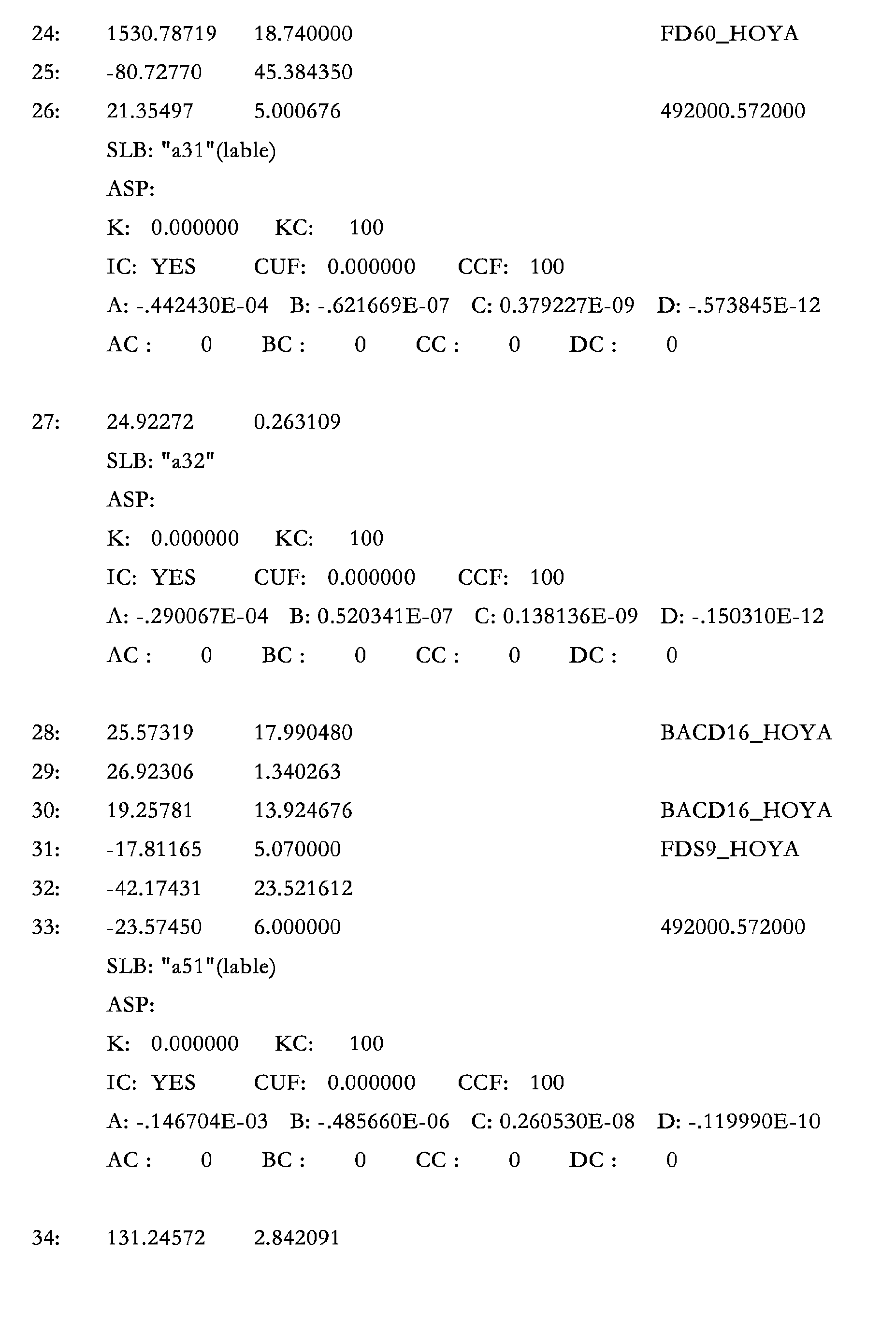

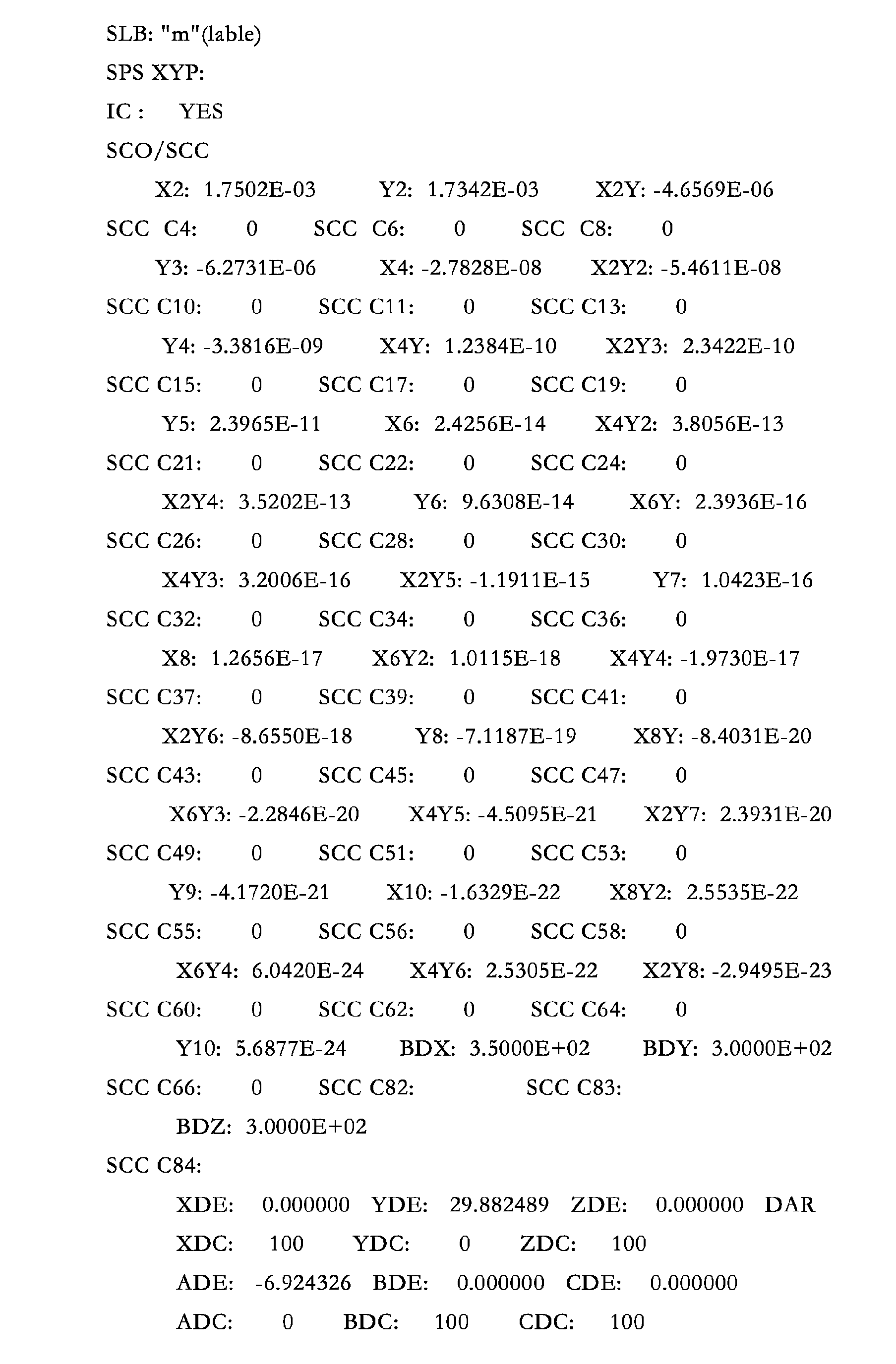

SPECIFICATION DATA NAO 0.20000 DIM MM WL 632.80 546.07 460.00 REF 2 WTW 1 1 1 XOB 0.00000 8.86000 4.43000 8.86000 4.43000 0.00000 6.64000 4.43000 8.86000 0.00000 6.64000 YOB 0.00000 0.00000 0.00000 -4.98000 -4.98000 -4.98000 -3.32000 4.98000 4.98000 4.98000 3.32000 WTF 1.00000 1.00000 1.00000 1.00000 1.00000 100.00000 1.00000 1.00000 1.00000 1.00000 1.00000 VUX 0.00000 0.00000 0.00000 0.00000 0.00000 0.00000 0.00000 0.00000 0.00000 0.00000 0.00000 VLX 0.00000 0.00000 0.00000 0.00000 0.00000 0.00000 0.00000 0.00000 0.00000 0.00000 0.00000 VUY 0.00000 0.00000 0.00000 0.00000 0.00000 0.00000 0.00000 0.00000 0.00000 0.00000 0.00000 VLY 0.00000 0.00000 0.00000 0.00000 0.00000 0.00000 0.00000 0.00000 0.00000 0.00000 0.00000 - APERTURE data not specified for surface Obj thru 43
REFRACTIVE INDICES GLASS CODE 632.80 546.07 460.00 FC5_HOYA 1.486014 1.489142 1.494026 BSC7_HOYA 1.515086 1.518719 1.524422 FDS9_HOYA 1.839565 1.855036 1.882227 FDS90_HOYA 1.839557 1.855048 1.882330 BACD16_HOYA 1.618237 1.622862 1.630197 FD60_HOYA 1.798849 1.812631 1.836802 NBFD15_HOYA 1.801166 1.811837 1.829942 492000.572000 1.490193 1.494050 1.500226 492000.572000 1.490193 1.494050 1.500226 492000.572000 1.490193 1.494050 1.500226 NBFD11_HOYA 1.782176 1.790150 1.803176 585000.300000 1.581055 1.589610 1.604296 530000.558000 1.528009 1.532263 1.539099 INFINITE CONJUGATES EFL -8.0684 BFL -379.4730 FFL -2.5970 FNO 0.0000 AT USED CONJUGATES RED -40.4490 FNO -101.1224 OBJ DIS 2.7964 TT 675.5649 IMG DIS 0.0000 OAL 672.7685 PARAXIAL IMAGE HT 134.2905 THI -53.1149 ANG 0.0000 ENTRANCE PUPIL DIA 0.4082E+10 THI 0.1000E+11 EXIT PUPIL DIA 3.2939 THI -379.4730 - Figures 5 and 6 illustrate a distribution of light spots at given field positions and image distortions exhibited by an image display apparatus according to an embodiment of the invention. As illustrated in Figure 6, image display apparatuses according to various embodiments of the invention exhibit good image quality. The use of refractive and reflective optical systems efficiently achieve a wide viewing angle, thereby providing the image display apparatus with a reduced thickness compared to a thickness of a conventional image display apparatus having a screen of comparable size.
- In the embodiments described above, optical projection systems and image display apparatuses include refractive and reflective optical systems to project an image produced by a display onto a screen with a wide viewing angle, thereby reducing a thickness of the image display apparatus. The optical projection system and the image display apparatus also generate predistortions, through a relay lens group and/or the refractive optical system, to compensate for distortion caused by the reflective optical system, thereby providing high quality images.
- Although a few embodiments of the invention have been shown and described, it will be appreciated by those skilled in the art that changes may be made in these embodiments without departing from the invention, the scope of which is defined in the appended claims.
Claims (52)
- An optical projection system (150), comprising:optical means (110, 130), arranged to receive a first image and to produce a second image from said first image; anda reflector (140) arranged to reflect the second image;characterised in that:said optical means (110, 130) is configured to generate first distortions in the second image to compensate for second distortions resulting from the reflection of the second image by said reflector (140).
- An image display apparatus comprising:an optical projection system (150) according to claim 1; andimage creation means (100) arranged to generate said first image.
- An optical projection system, comprising:a relay lens group to produce an intermediate image from an image created by a display and to generate a first distortion in the intermediate image;a projection lens group to enlarge and project the intermediate image that passes through the relay lens group and to generate a second distortion in the projected image; anda reflector to reflect the image enlarged by the projection lens group onto a screen at a wide viewing angle,wherein the first and second distortions compensate for a third distortion caused by the reflector.
- The optical projection system of claim 3, wherein the reflector comprises an aspherical mirror.
- The optical projection system of claim 3, wherein the reflector has a negative refractive power.
- The optical projection system of claim 3, further comprising:first and second optical path changers to change optical paths between the relay lens group and the projection lens group and between the projection lens group and the reflector, respectively.
- The optical projection system of claim 6, further comprising:a third optical path changer disposed within the relay lens group.
- The optical projection system of claim 6, wherein the first, second, and third optical path changers comprise one of a mirror and a total reflection prism.
- The optical projection system of claim 3, wherein an optical axis of the display is coaxial with optical axes of the relay lens group and the projection lens group.
- The optical projection system of claim 9, wherein an optical axis of the reflector is offset from the optical axis of the display.
- The optical projection system of claim 3, wherein the first and second distortions are spool distortions, and the third distortion caused by the reflector is a barrel distortion.
- The optical projection system of claim 3, further comprising:a total reflection prism disposed between the display and the relay lens group to receive the image created by the display and to reflect the received image to the relay lens group.
- The optical projection system of claim 3, wherein the projection lens group performs a first enlarging operation on the image and the reflector performs a second enlarging operation on the image.
- The optical projection system of claim 3, wherein the projection lens group enlarges the image by a first angle and provides the enlarged image to the reflector at the first angle, and the reflector enlarges the image by a second angle to be directed onto the screen for viewing at the second angle.
- The optical projection system of claim 3, further comprising:a series of reflectors to bend an optical path of the image through the optical projection system such that the relay lens group and the projection lens group are arranged below the screen and the reflector is arranged behind a lower portion of the screen.
- An optical projection system usable with an image display apparatus, comprising:a preliminary distortion unit to receive an image created by an image creation unit and to induce a preliminary distortion in the received image; andan image enlarging unit to receive the preliminary distorted image, to enlarge the received image while inducing a distortion in the received image, and to project the enlarged image onto a screen,wherein the preliminary distortion compensates for the distortion.
- The optical projection system of claim 16, wherein the preliminary distortion part comprises at least one of a relay lens group, a projection lens group, and a refractive optical system.
- The optical projection system of claim 17, wherein the image enlarging unit comprises a reflective optical system.
- The optical projection system of claim 16, wherein the preliminary distortion unit receives the created image in an opposite direction from the screen and provides the preliminary distorted image toward a rear direction of the image display apparatus, and the image enlarging unit reflects the enlarged image back toward a forward direction of the image display apparatus onto the screen.
- The optical projection system of claim 16, wherein the preliminary distortion comprises a spool distortion and the distortion comprises barrel distortion.
- The optical projection system of claim 16, wherein the preliminary distortion unit comprises:a relay lens group to produce an intermediate image from the image created by the image creation unit and to generate a first distortion in the intermediate image; anda projection lens group to enlarge and project the intermediate image that passes through the relay lens group to the image enlarging unit and to generate a second distortion in the projected image.
- The optical projection system of claim 21, wherein the image enlarging unit comprises a reflector to reflect the image enlarged by the projection lens group onto the screen at a wide viewing angle such that the first and second distortions generated in the image compensate for distortion generated when the image is reflected at the wide viewing angle onto the screen.
- An optical projection system, comprising:a refractive optical system to enlarge and transmit an image produced by a display;a reflective optical system to reflect the image transmitted by the refractive optical system at a wide viewing angle; anda relay lens group disposed between the display and the reflective optical system to preliminarily induce a first distortion to compensate for a third distortion caused by the reflective optical system,wherein the refractive optical system preliminarily induces a second distortion that is used in combination with the first distortion to compensate for the third distortion caused by the reflective optical system.
- The optical projection system of claim 23, wherein the reflective optical system comprises an aspherical mirror.
- The optical projection system of claim 23, wherein the reflective optical system has a negative refractive power.
- The optical projection system of claim 23, further comprising:first and second optical path changers to change optical paths between the relay lens group and the refractive optical system and between the refractive optical system and the reflective optical system, respectively.
- The optical projection system of claim 26, further comprising:a third optical path changer disposed within the relay lens group.
- The optical projection system of claim 26, wherein the first, second, and third optical path changers comprise one of a mirror and a total reflection prism.
- The optical projection system of claim 23, wherein an optical axis of the display is coaxial with optical axes of the relay lens group and the refractive optical system.
- The optical projection system of claim 29, wherein an optical axis of the reflective optical system is offset from the optical axis of the display.
- The optical projection system of claim 23, wherein the first and second distortions are spool distortions, and the third distortion caused by the reflective optical system is a barrel distortion.
- An image display apparatus including a display to receive a beam emitted by a light source and to produce an image by processing the received beam according to an input image signal and an optical projection system to enlarge and project the produced image onto a screen, and the optical projection system comprises:a relay lens group to produce an intermediate image from the image created by the display and to generate a first distortion in the intermediate image;a projection lens group to enlarge and project the intermediate image that passes through the relay lens group and to generate a second distortion in the projected image; anda reflector to reflect the image enlarged by the projection lens group onto the screen at a wide viewing angle,wherein the first and second distortions are used to compensate for a third distortion caused by the reflector.
- The apparatus of claim 32, wherein the reflector comprises an aspherical mirror.
- The apparatus of claim 32, wherein the reflector has a negative refractive power.
- The apparatus of claim 32, wherein the optical projection system further comprises first and second optical path changers to change optical paths between the relay lens group and the projection lens group and between the projection lens group and the reflector, respectively.
- The apparatus of claim 35, wherein the optical projection system further comprises a third optical path changer disposed within the relay lens group.
- The apparatus of claim 35, wherein the first, second, and third optical path changers comprise one of a mirror and a total reflection prism.
- The apparatus of claim 32, wherein an optical axis of the display is coaxial with optical axes of the relay lens group and the projection lens group.
- The apparatus of claim 38, wherein an optical axis of the reflector is offset from the optical axis of the display.
- The apparatus of claim 32, wherein the first and second distortions are spool distortions, and the third distortion caused by the reflector is a barrel distortion.
- An image display apparatus including a display to receive a beam emitted by a light source and to produce an image by processing the received beam according to an input image signal and an optical projection system to enlarge and project the produced image onto a screen, and the optical projection system comprises:a refractive optical system to enlarge and transmit the image produced by the display;a reflective optical system to reflect the image transmitted by the refractive optical system at a wide viewing angle; anda relay lens group disposed between the display and the reflective optical system to preliminarily induce a first distortion to compensate for a third distortion caused by the reflective optical system,wherein the refractive optical system preliminarily induces a second distortion that is used in combination with the first distortion to compensate for the third distortion caused by the reflective optical system.
- The apparatus of claim 41, wherein the reflective optical system comprises an aspherical mirror.
- The apparatus of claim 41, wherein the reflective optical system has a negative refractive power.
- The apparatus of claim 41, wherein the optical projection system further comprises first and second optical path changers to change optical paths between the relay lens group and the refractive optical system and between the refractive optical system and the reflective optical system, respectively.
- An image display apparatus to display an image on a screen, comprising:an image creation unit to create an image; andan optical projection system, comprising:wherein the preliminary distortion compensates for the distortion.a preliminary distortion unit to receive the image created by an image creation unit and to induce a preliminary distortion in the received image; and an image enlarging unit to receive the preliminary distorted image, to enlarge the received image while inducing a distortion in the received image, and to project the enlarged image onto a screen,
- An optical projection system, comprising:a display to generate an image;a first lens group to generate a first intermediate image having a first distortion from the image;a second lens group to generate a second intermediate image having a second distortion from the first intermediate image;a reflector to introduce a third distortion into the second intermediate image to compensate for the first and second distortions, and to generate a third intermediate image; anda screen to display the third intermediate image without the first and second distortions.
- The system of claim 46, wherein the first and second intermediate images have a pincushion shape, and the reflector generates the third intermediate image to have a rectangular shape by introducing the third distortion having a barrel shape.
- The system of claim 46, wherein the third intermediate image is enlarged from the second intermediate image.
- An image display apparatus, comprising:a screen disposed at a front side of the image display apparatus;an imager creator disposed under the screen at the front side of the image display apparatus to create an image having a plurality of light beams and to transmit the plurality of light beams in a rear direction;a refractive optical system to receive the plurality of light beams from the image creator and to relay the plurality of light beams along the rear direction while enlarging an angle along which the plurality of light beams propagate and while introducing a predetermined distortion in the image; anda reflective optical system disposed at a rear side of the image display apparatus to receive the plurality of light beams from the refractive optical system and to reflect the plurality of light beams onto the screen while enlarging the image and introducing another distortion in the image.
- A method of an optical projection system, the method comprising:receiving an image created by an image creation unit;creating a predistortion in the received image and providing the predistorted image to a reflector; andreflecting the predistorted image toward a screen while introducing a distortion that is compensated for by the predistortion.
- The method of claim 50, wherein the predistoration comprises one or more spool distortions and the distortion comprises a barrel distortion.
- The method of claim 50, wherein:creating the predistortion in the received image comprises performing a first enlarging operation using a projection lens group; andreflecting of the predistorted image toward the screen comprises performing a second enlarging operation using the reflector.
Applications Claiming Priority (1)
| Application Number | Priority Date | Filing Date | Title |
|---|---|---|---|
| KR1020040077374A KR100677134B1 (en) | 2004-09-24 | 2004-09-24 | Slim projection optical system and image display device |
Publications (3)
| Publication Number | Publication Date |
|---|---|
| EP1640783A2 true EP1640783A2 (en) | 2006-03-29 |
| EP1640783A3 EP1640783A3 (en) | 2006-07-12 |
| EP1640783B1 EP1640783B1 (en) | 2008-03-19 |
Family
ID=36098600
Family Applications (1)
| Application Number | Title | Priority Date | Filing Date |
|---|---|---|---|
| EP05108540A Expired - Fee Related EP1640783B1 (en) | 2004-09-24 | 2005-09-16 | Optical projection system for an image display apparatus |
Country Status (6)
| Country | Link |
|---|---|
| US (1) | US7448756B2 (en) |
| EP (1) | EP1640783B1 (en) |
| JP (1) | JP2006091867A (en) |
| KR (1) | KR100677134B1 (en) |
| CN (1) | CN100381867C (en) |
| DE (1) | DE602005005410D1 (en) |
Cited By (1)
| Publication number | Priority date | Publication date | Assignee | Title |
|---|---|---|---|---|
| EP2730961A4 (en) * | 2011-07-05 | 2015-07-15 | Nittoh Kogaku Kk | Projection optical assembly and projector device |
Families Citing this family (17)
| Publication number | Priority date | Publication date | Assignee | Title |
|---|---|---|---|---|
| JP4910384B2 (en) * | 2005-12-16 | 2012-04-04 | 株式会社日立製作所 | Free-form optical element and projection optical unit or projection-type image display apparatus including the same |
| DE102006008589A1 (en) * | 2006-02-24 | 2007-09-06 | Carl Zeiss Jena Gmbh | Arrangement for image representation in rear projection-television set, has projection optics, where light comes from lighting device, over third partial optics at angle, lying at common Z-axis of former and latter partial optics |
| US7959302B2 (en) * | 2006-03-28 | 2011-06-14 | Seiko Epson Corporation | Display device and game machine |
| US8319832B2 (en) * | 2008-01-31 | 2012-11-27 | Denso Corporation | Input apparatus and imaging apparatus |
| US9244287B2 (en) * | 2008-05-09 | 2016-01-26 | Reald Inc. | Optical systems with compact back focal lengths |
| JP2010014815A (en) | 2008-07-01 | 2010-01-21 | Mitsubishi Electric Corp | Projection type display device |
| JP5106309B2 (en) | 2008-08-07 | 2012-12-26 | 三菱電機株式会社 | Projection display |
| JP5484098B2 (en) * | 2009-03-18 | 2014-05-07 | 三菱電機株式会社 | Projection optical system and image display apparatus |
| US8279527B2 (en) * | 2009-06-16 | 2012-10-02 | Delta Electronics, Inc. | Wide-angle projection optical system |
| KR20110120590A (en) * | 2010-04-29 | 2011-11-04 | 삼성전자주식회사 | Optical system and image projection apparatus |
| JP5621583B2 (en) * | 2010-12-27 | 2014-11-12 | 株式会社リコー | Projection optical system and image projection apparatus |
| JP5163794B2 (en) * | 2011-09-20 | 2013-03-13 | 株式会社日立製作所 | Projection type image display device |
| CN103293642B (en) * | 2012-03-02 | 2015-08-26 | 扬明光学股份有限公司 | Projection lens and projection arrangement |
| JP6243353B2 (en) * | 2012-12-28 | 2017-12-06 | 株式会社nittoh | Projection optical system and projector apparatus |
| JP6736366B2 (en) * | 2015-06-19 | 2020-08-05 | キヤノン株式会社 | Imaging optical system, optical device, and image projection device |
| JP6847003B2 (en) * | 2017-08-17 | 2021-03-24 | 富士フイルム株式会社 | Projection optical system and projection type display device |
| US11528458B2 (en) | 2018-12-07 | 2022-12-13 | Sony Group Corporation | Image display apparatus and projection optical system |
Citations (5)
| Publication number | Priority date | Publication date | Assignee | Title |
|---|---|---|---|---|
| WO1998008141A1 (en) * | 1996-08-23 | 1998-02-26 | Robin Christopher Colclough | Image projecting apparatus |
| US20010050758A1 (en) * | 2000-05-10 | 2001-12-13 | Hiroshi Suzuki | Image display device and adjustment for alignment |
| US20040032653A1 (en) * | 2002-08-16 | 2004-02-19 | Gohman Jeffrey Alan | Wide angle lens system having a distorted intermediate image |
| US20040156117A1 (en) * | 2003-02-06 | 2004-08-12 | Atsushi Takaura | Projection optical system, magnification projection optical system, magnification projection apparatus, and image projection apparatus |
| US20050174545A1 (en) * | 2004-02-09 | 2005-08-11 | Jong-Soo Lee | Optical projection system and image display device having the same |
Family Cites Families (17)
| Publication number | Priority date | Publication date | Assignee | Title |
|---|---|---|---|---|
| US5274406A (en) * | 1987-12-29 | 1993-12-28 | Asahi Kogaku Kogyo Kabushiki Kaisha | Image projecting device |
| US5692820A (en) * | 1992-02-20 | 1997-12-02 | Kopin Corporation | Projection monitor |
| US5625495A (en) * | 1994-12-07 | 1997-04-29 | U.S. Precision Lens Inc. | Telecentric lens systems for forming an image of an object composed of pixels |
| JPH09138349A (en) * | 1995-09-11 | 1997-05-27 | Semiconductor Energy Lab Co Ltd | Display device |
| KR100471458B1 (en) | 1997-03-29 | 2005-06-28 | 엘지전자 주식회사 | Lens for LCD Projection TV |
| KR200156536Y1 (en) | 1997-06-02 | 1999-09-01 | 김영환 | Projector of rear projection tv |
| JP4240342B2 (en) | 1998-03-20 | 2009-03-18 | フジノン株式会社 | Retro focus lens |
| JPH11305337A (en) | 1998-04-17 | 1999-11-05 | Seiko Epson Corp | Rear projection type display device |
| JP2000250131A (en) * | 1999-03-01 | 2000-09-14 | Lg Electronics Inc | Projection type display |
| KR20010073004A (en) | 1999-06-28 | 2001-07-31 | 요트.게.아. 롤페즈 | Projection display device comprising an integrator device provided with a tunnel prism |
| KR100534574B1 (en) | 2001-04-24 | 2005-12-07 | 삼성에스디아이 주식회사 | Projection System and Projection Method |
| KR100410964B1 (en) | 2001-07-27 | 2003-12-18 | 삼성전기주식회사 | Projection lens of projection display apparatus |
| US7714943B2 (en) * | 2002-06-12 | 2010-05-11 | Geo Semiconductor Inc. | Ultra-thin image projection system |
| JP3951833B2 (en) * | 2002-06-28 | 2007-08-01 | 日本ビクター株式会社 | Material presentation device |
| US7090354B2 (en) * | 2002-08-16 | 2006-08-15 | Infocus Corporation | Projection device and screen |
| JP4186591B2 (en) * | 2002-11-01 | 2008-11-26 | 日本ビクター株式会社 | Imaging optical system and data presentation device |
| JP4086686B2 (en) * | 2003-03-18 | 2008-05-14 | キヤノン株式会社 | Projection optical system, projection-type image display device and image display system |
-
2004
- 2004-09-24 KR KR1020040077374A patent/KR100677134B1/en not_active IP Right Cessation
-
2005
- 2005-09-01 JP JP2005253449A patent/JP2006091867A/en active Pending
- 2005-09-16 DE DE602005005410T patent/DE602005005410D1/en active Active
- 2005-09-16 EP EP05108540A patent/EP1640783B1/en not_active Expired - Fee Related
- 2005-09-19 CN CNB2005101048117A patent/CN100381867C/en not_active Expired - Fee Related
- 2005-09-22 US US11/231,885 patent/US7448756B2/en not_active Expired - Fee Related
Patent Citations (5)
| Publication number | Priority date | Publication date | Assignee | Title |
|---|---|---|---|---|
| WO1998008141A1 (en) * | 1996-08-23 | 1998-02-26 | Robin Christopher Colclough | Image projecting apparatus |
| US20010050758A1 (en) * | 2000-05-10 | 2001-12-13 | Hiroshi Suzuki | Image display device and adjustment for alignment |
| US20040032653A1 (en) * | 2002-08-16 | 2004-02-19 | Gohman Jeffrey Alan | Wide angle lens system having a distorted intermediate image |
| US20040156117A1 (en) * | 2003-02-06 | 2004-08-12 | Atsushi Takaura | Projection optical system, magnification projection optical system, magnification projection apparatus, and image projection apparatus |
| US20050174545A1 (en) * | 2004-02-09 | 2005-08-11 | Jong-Soo Lee | Optical projection system and image display device having the same |
Non-Patent Citations (2)
| Title |
|---|
| PATENT ABSTRACTS OF JAPAN vol. 1997, no. 09, 30 September 1997 (1997-09-30) -& JP 09 138349 A (SEMICONDUCTOR ENERGY LAB CO LTD), 27 May 1997 (1997-05-27) * |
| PATENT ABSTRACTS OF JAPAN vol. 2000, no. 12, 3 January 2001 (2001-01-03) -& JP 2000 250131 A (LG ELECTRONICS INC), 14 September 2000 (2000-09-14) * |
Cited By (4)
| Publication number | Priority date | Publication date | Assignee | Title |
|---|---|---|---|---|
| EP2730961A4 (en) * | 2011-07-05 | 2015-07-15 | Nittoh Kogaku Kk | Projection optical assembly and projector device |
| US9372388B2 (en) | 2011-07-05 | 2016-06-21 | Nittoh Kogaku K.K. | Projection optical assembly with multiple refractive optical systems and related projector device |
| US10310366B2 (en) | 2011-07-05 | 2019-06-04 | Nittoh Inc. | Projection optical assembly and projector device |
| US10754239B2 (en) | 2011-07-05 | 2020-08-25 | Nittoh Inc. | Projection optical assembly and projector device |
Also Published As
| Publication number | Publication date |
|---|---|
| US7448756B2 (en) | 2008-11-11 |
| CN100381867C (en) | 2008-04-16 |
| KR20060028278A (en) | 2006-03-29 |
| CN1752798A (en) | 2006-03-29 |
| JP2006091867A (en) | 2006-04-06 |
| US20060066760A1 (en) | 2006-03-30 |
| DE602005005410D1 (en) | 2008-04-30 |
| EP1640783A3 (en) | 2006-07-12 |
| EP1640783B1 (en) | 2008-03-19 |
| KR100677134B1 (en) | 2007-02-02 |
Similar Documents
| Publication | Publication Date | Title |
|---|---|---|
| EP1640783B1 (en) | Optical projection system for an image display apparatus | |
| EP1965254B1 (en) | Projection type display apparatus | |
| US9983394B2 (en) | Projection optical system and image display apparatus | |
| US6715885B2 (en) | Display device with screen having curved surface | |
| US7009765B2 (en) | Wide angle lens system having a distorted intermediate image | |
| US6752500B1 (en) | Rear surface projection type display device | |
| US7959305B2 (en) | Light recycling in a micromirror-based projection display system | |
| US7789516B2 (en) | Projection type image display device | |
| US6406150B1 (en) | Compact rear projections system | |
| JP3429291B2 (en) | Projection lens for projection display device | |
| US8901473B2 (en) | Projection optical system having an aperture to limit quantity of light to a refractive optical system, and image display device using the same | |
| EP2410378A1 (en) | Projection optical system and image projection device | |
| US20090021703A1 (en) | Projection optical system, magnification projection optical system, magnification projection apparatus, and image projection apparatus | |
| JPH07168123A (en) | Color-image projecting apparatus and optical system for conversion used in apparatus thereof | |
| EP1802113A1 (en) | Backlighting system for a liquid-crystal display screen and corresponding display device | |
| CN109870791B (en) | Short focus image projection device | |
| CN111208701A (en) | Laser projection device | |
| JP2004279988A (en) | Projection optical system | |
| JP2004177654A (en) | Projection picture display device | |
| CN110456600B (en) | Projection lens and laser projection device | |
| CN110456599B (en) | Projection imaging system and laser projection device | |
| Ley et al. | Imaging and non-imaging illumination of DLP for high resolution headlamps | |
| US20220299790A1 (en) | Projector and projection method | |
| CN112578610B (en) | Projection lens and laser projection equipment | |
| CA2305268C (en) | Optical projection apparatus and method |
Legal Events
| Date | Code | Title | Description |
|---|---|---|---|
| PUAI | Public reference made under article 153(3) epc to a published international application that has entered the european phase |
Free format text: ORIGINAL CODE: 0009012 |
|
| AK | Designated contracting states |
Kind code of ref document: A2 Designated state(s): AT BE BG CH CY CZ DE DK EE ES FI FR GB GR HU IE IS IT LI LT LU LV MC NL PL PT RO SE SI SK TR |
|
| AX | Request for extension of the european patent |
Extension state: AL BA HR MK YU |
|
| PUAL | Search report despatched |
Free format text: ORIGINAL CODE: 0009013 |
|
| AK | Designated contracting states |
Kind code of ref document: A3 Designated state(s): AT BE BG CH CY CZ DE DK EE ES FI FR GB GR HU IE IS IT LI LT LU LV MC NL PL PT RO SE SI SK TR |
|
| AX | Request for extension of the european patent |
Extension state: AL BA HR MK YU |
|
| RIC1 | Information provided on ipc code assigned before grant |
Ipc: G02B 17/08 20060101ALI20060606BHEP Ipc: G03B 21/28 20060101ALI20060606BHEP Ipc: H04N 5/74 20060101ALI20060606BHEP Ipc: H04N 9/31 20060101ALI20060606BHEP Ipc: G02B 27/18 20060101AFI20051222BHEP |
|
| 17P | Request for examination filed |
Effective date: 20070108 |
|
| R17C | First examination report despatched (corrected) |
Effective date: 20070208 |
|
| AKX | Designation fees paid |
Designated state(s): DE FR GB IT NL |
|
| GRAP | Despatch of communication of intention to grant a patent |
Free format text: ORIGINAL CODE: EPIDOSNIGR1 |
|
| GRAS | Grant fee paid |
Free format text: ORIGINAL CODE: EPIDOSNIGR3 |
|
| GRAA | (expected) grant |
Free format text: ORIGINAL CODE: 0009210 |
|
| AK | Designated contracting states |
Kind code of ref document: B1 Designated state(s): DE FR GB IT NL |
|
| REG | Reference to a national code |
Ref country code: GB Ref legal event code: FG4D |
|
| REF | Corresponds to: |
Ref document number: 602005005410 Country of ref document: DE Date of ref document: 20080430 Kind code of ref document: P |
|
| NLV1 | Nl: lapsed or annulled due to failure to fulfill the requirements of art. 29p and 29m of the patents act | ||
| PG25 | Lapsed in a contracting state [announced via postgrant information from national office to epo] |
Ref country code: NL Free format text: LAPSE BECAUSE OF FAILURE TO SUBMIT A TRANSLATION OF THE DESCRIPTION OR TO PAY THE FEE WITHIN THE PRESCRIBED TIME-LIMIT Effective date: 20080319 |
|
| EN | Fr: translation not filed | ||
| PLBE | No opposition filed within time limit |
Free format text: ORIGINAL CODE: 0009261 |
|
| STAA | Information on the status of an ep patent application or granted ep patent |
Free format text: STATUS: NO OPPOSITION FILED WITHIN TIME LIMIT |
|
| PG25 | Lapsed in a contracting state [announced via postgrant information from national office to epo] |
Ref country code: DE Free format text: LAPSE BECAUSE OF FAILURE TO SUBMIT A TRANSLATION OF THE DESCRIPTION OR TO PAY THE FEE WITHIN THE PRESCRIBED TIME-LIMIT Effective date: 20080620 |
|
| 26N | No opposition filed |
Effective date: 20081222 |
|
| PG25 | Lapsed in a contracting state [announced via postgrant information from national office to epo] |
Ref country code: IT Free format text: LAPSE BECAUSE OF FAILURE TO SUBMIT A TRANSLATION OF THE DESCRIPTION OR TO PAY THE FEE WITHIN THE PRESCRIBED TIME-LIMIT Effective date: 20080319 |
|
| PG25 | Lapsed in a contracting state [announced via postgrant information from national office to epo] |
Ref country code: FR Free format text: LAPSE BECAUSE OF FAILURE TO SUBMIT A TRANSLATION OF THE DESCRIPTION OR TO PAY THE FEE WITHIN THE PRESCRIBED TIME-LIMIT Effective date: 20090109 |
|
| PGFP | Annual fee paid to national office [announced via postgrant information from national office to epo] |
Ref country code: GB Payment date: 20130905 Year of fee payment: 9 |
|
| GBPC | Gb: european patent ceased through non-payment of renewal fee |
Effective date: 20140916 |
|
| PG25 | Lapsed in a contracting state [announced via postgrant information from national office to epo] |
Ref country code: GB Free format text: LAPSE BECAUSE OF NON-PAYMENT OF DUE FEES Effective date: 20140916 |