EP1639345B1 - Standardisolierglaseinheiten mit bekannten konzentrationen eines gases - Google Patents
Standardisolierglaseinheiten mit bekannten konzentrationen eines gases Download PDFInfo
- Publication number
- EP1639345B1 EP1639345B1 EP04777206A EP04777206A EP1639345B1 EP 1639345 B1 EP1639345 B1 EP 1639345B1 EP 04777206 A EP04777206 A EP 04777206A EP 04777206 A EP04777206 A EP 04777206A EP 1639345 B1 EP1639345 B1 EP 1639345B1
- Authority
- EP
- European Patent Office
- Prior art keywords
- unit
- calibration standard
- calibration
- glass
- spacer
- Prior art date
- Legal status (The legal status is an assumption and is not a legal conclusion. Google has not performed a legal analysis and makes no representation as to the accuracy of the status listed.)
- Expired - Lifetime
Links
- 239000011521 glass Substances 0.000 title claims abstract description 60
- XKRFYHLGVUSROY-UHFFFAOYSA-N Argon Chemical compound [Ar] XKRFYHLGVUSROY-UHFFFAOYSA-N 0.000 claims abstract description 72
- 239000007789 gas Substances 0.000 claims abstract description 44
- 229910052786 argon Inorganic materials 0.000 claims abstract description 36
- 125000006850 spacer group Chemical group 0.000 claims description 38
- 238000000576 coating method Methods 0.000 claims description 9
- 239000000463 material Substances 0.000 claims description 8
- 239000011248 coating agent Substances 0.000 claims description 5
- 239000007787 solid Substances 0.000 claims description 4
- XAGFODPZIPBFFR-UHFFFAOYSA-N aluminium Chemical compound [Al] XAGFODPZIPBFFR-UHFFFAOYSA-N 0.000 claims description 3
- 239000010935 stainless steel Substances 0.000 claims description 3
- 229910001220 stainless steel Inorganic materials 0.000 claims description 3
- 229910052782 aluminium Inorganic materials 0.000 claims description 2
- 239000004411 aluminium Substances 0.000 claims 1
- 238000000926 separation method Methods 0.000 claims 1
- 238000005259 measurement Methods 0.000 abstract description 25
- 238000000034 method Methods 0.000 abstract description 16
- 238000010276 construction Methods 0.000 abstract description 6
- 239000011261 inert gas Substances 0.000 abstract description 4
- 239000000203 mixture Substances 0.000 abstract description 4
- 239000001301 oxygen Substances 0.000 abstract description 2
- 229910052760 oxygen Inorganic materials 0.000 abstract description 2
- MYMOFIZGZYHOMD-UHFFFAOYSA-N Dioxygen Chemical compound O=O MYMOFIZGZYHOMD-UHFFFAOYSA-N 0.000 abstract 1
- 238000004519 manufacturing process Methods 0.000 description 22
- 238000012360 testing method Methods 0.000 description 11
- 229910052751 metal Inorganic materials 0.000 description 6
- 239000002184 metal Substances 0.000 description 6
- 239000000565 sealant Substances 0.000 description 6
- 230000000712 assembly Effects 0.000 description 4
- 238000000429 assembly Methods 0.000 description 4
- 238000011088 calibration curve Methods 0.000 description 3
- 230000002093 peripheral effect Effects 0.000 description 3
- 238000012545 processing Methods 0.000 description 3
- 125000000484 butyl group Chemical group [H]C([*])([H])C([H])([H])C([H])([H])C([H])([H])[H] 0.000 description 2
- 230000003287 optical effect Effects 0.000 description 2
- 239000013307 optical fiber Substances 0.000 description 2
- 229920001296 polysiloxane Polymers 0.000 description 2
- 238000010998 test method Methods 0.000 description 2
- 230000032258 transport Effects 0.000 description 2
- 229910000838 Al alloy Inorganic materials 0.000 description 1
- 229920002367 Polyisobutene Polymers 0.000 description 1
- 238000001069 Raman spectroscopy Methods 0.000 description 1
- 229920002323 Silicone foam Polymers 0.000 description 1
- 230000001070 adhesive effect Effects 0.000 description 1
- QVGXLLKOCUKJST-UHFFFAOYSA-N atomic oxygen Chemical compound [O] QVGXLLKOCUKJST-UHFFFAOYSA-N 0.000 description 1
- 230000002596 correlated effect Effects 0.000 description 1
- 230000000875 corresponding effect Effects 0.000 description 1
- 238000012217 deletion Methods 0.000 description 1
- 230000037430 deletion Effects 0.000 description 1
- 238000000151 deposition Methods 0.000 description 1
- 230000000994 depressogenic effect Effects 0.000 description 1
- 239000012943 hotmelt Substances 0.000 description 1
- -1 i.e. Substances 0.000 description 1
- 239000012212 insulator Substances 0.000 description 1
- 238000001307 laser spectroscopy Methods 0.000 description 1
- 230000007246 mechanism Effects 0.000 description 1
- 229910001092 metal group alloy Inorganic materials 0.000 description 1
- 239000004033 plastic Substances 0.000 description 1
- 229920003023 plastic Polymers 0.000 description 1
- 229920001021 polysulfide Polymers 0.000 description 1
- 239000005077 polysulfide Substances 0.000 description 1
- 150000008117 polysulfides Polymers 0.000 description 1
- 229920002635 polyurethane Polymers 0.000 description 1
- 239000004814 polyurethane Substances 0.000 description 1
- 238000010926 purge Methods 0.000 description 1
- 238000007789 sealing Methods 0.000 description 1
- 239000013514 silicone foam Substances 0.000 description 1
- 239000012815 thermoplastic material Substances 0.000 description 1
- 238000005406 washing Methods 0.000 description 1
Images




Classifications
-
- G—PHYSICS
- G01—MEASURING; TESTING
- G01N—INVESTIGATING OR ANALYSING MATERIALS BY DETERMINING THEIR CHEMICAL OR PHYSICAL PROPERTIES
- G01N21/00—Investigating or analysing materials by the use of optical means, i.e. using sub-millimetre waves, infrared, visible or ultraviolet light
- G01N21/62—Systems in which the material investigated is excited whereby it emits light or causes a change in wavelength of the incident light
- G01N21/66—Systems in which the material investigated is excited whereby it emits light or causes a change in wavelength of the incident light electrically excited, e.g. electroluminescence
- G01N21/67—Systems in which the material investigated is excited whereby it emits light or causes a change in wavelength of the incident light electrically excited, e.g. electroluminescence using electric arcs or discharges
-
- G—PHYSICS
- G01—MEASURING; TESTING
- G01N—INVESTIGATING OR ANALYSING MATERIALS BY DETERMINING THEIR CHEMICAL OR PHYSICAL PROPERTIES
- G01N21/00—Investigating or analysing materials by the use of optical means, i.e. using sub-millimetre waves, infrared, visible or ultraviolet light
- G01N21/17—Systems in which incident light is modified in accordance with the properties of the material investigated
- G01N21/25—Colour; Spectral properties, i.e. comparison of effect of material on the light at two or more different wavelengths or wavelength bands
- G01N21/27—Colour; Spectral properties, i.e. comparison of effect of material on the light at two or more different wavelengths or wavelength bands using photo-electric detection ; circuits for computing concentration
- G01N21/274—Calibration, base line adjustment, drift correction
- G01N21/278—Constitution of standards
-
- E—FIXED CONSTRUCTIONS
- E06—DOORS, WINDOWS, SHUTTERS, OR ROLLER BLINDS IN GENERAL; LADDERS
- E06B—FIXED OR MOVABLE CLOSURES FOR OPENINGS IN BUILDINGS, VEHICLES, FENCES OR LIKE ENCLOSURES IN GENERAL, e.g. DOORS, WINDOWS, BLINDS, GATES
- E06B3/00—Window sashes, door leaves, or like elements for closing wall or like openings; Layout of fixed or moving closures, e.g. windows in wall or like openings; Features of rigidly-mounted outer frames relating to the mounting of wing frames
- E06B3/66—Units comprising two or more parallel glass or like panes permanently secured together
- E06B3/677—Evacuating or filling the gap between the panes ; Equilibration of inside and outside pressure; Preventing condensation in the gap between the panes; Cleaning the gap between the panes
-
- G—PHYSICS
- G01—MEASURING; TESTING
- G01N—INVESTIGATING OR ANALYSING MATERIALS BY DETERMINING THEIR CHEMICAL OR PHYSICAL PROPERTIES
- G01N21/00—Investigating or analysing materials by the use of optical means, i.e. using sub-millimetre waves, infrared, visible or ultraviolet light
- G01N21/84—Systems specially adapted for particular applications
- G01N21/88—Investigating the presence of flaws or contamination
- G01N21/95—Investigating the presence of flaws or contamination characterised by the material or shape of the object to be examined
- G01N21/958—Inspecting transparent materials or objects, e.g. windscreens
-
- Y—GENERAL TAGGING OF NEW TECHNOLOGICAL DEVELOPMENTS; GENERAL TAGGING OF CROSS-SECTIONAL TECHNOLOGIES SPANNING OVER SEVERAL SECTIONS OF THE IPC; TECHNICAL SUBJECTS COVERED BY FORMER USPC CROSS-REFERENCE ART COLLECTIONS [XRACs] AND DIGESTS
- Y10—TECHNICAL SUBJECTS COVERED BY FORMER USPC
- Y10T—TECHNICAL SUBJECTS COVERED BY FORMER US CLASSIFICATION
- Y10T436/00—Chemistry: analytical and immunological testing
- Y10T436/10—Composition for standardization, calibration, simulation, stabilization, preparation or preservation; processes of use in preparation for chemical testing
Definitions
- This invention relates to standard insulating glass units having known concentrations of a gas for use in calibration.
- IGUs Insulating glass units
- Spacers are typically made of metal, butyt materials, silicone foam or plastic materials. They are usually of tubular configuration, and are formed so as to have two flat sides that face the confronting surfaces of the glass panes. The metal spacers are bent so as to conform to the periphery of the glass panes.
- the spacers are adhered to the glass panes with a sealant that is gas-impermeable, such as polyisobuytlene.
- An additional sealant, with strong adhesion force, such as silicone is commonly applied around the outside edges of the IGU.
- EPO916801 discloses on insulating glass unit in which the spacer is obtained by depositing an endless tape of thermoplastic material around the periphery of two glass panes.
- the space between the panes of glass, or interpane space may be filled with a proper amount of a gas such as argon.
- the IGU must be filled with the proper amount of gas.
- the amount of gas flowed into the interpane space is gauged by flowing gas at a known rate for a specified period of time.
- At least one pane surface of an insulating glass unit is coated with a low emissivity coating to prevent conduction of heat through the glass.
- These coatings are known in the industry to be called low emissivity coatings. These coatings reflect long wave (room side) energy which assists in reducing winter U values. These coatings can result in the reflectance of color from the glass surface. Typically, color reflectance is undesirable. Therefore, for aesthetic purposes, it is desirable to manufacture glass and IGUs that reflect at wavelengths in the blue or blue/green range.
- the interpane space is filled with an inert gas, i.e., argon.
- argon an inert gas
- the percentage of argon usually ranges from about 40% to about 100%. It is important to know the inert gas content contained in an IGU and there have been various methods of making such a determination.
- One nondestructive method uses a laser and Raman spectroscopy to determine certain gas content.
- the system does not directly measure argon as it can only measure diatomic gases, i.e. O 2 and N 2 .
- Argon percentage is then determined by subtracting the O 2 content and N 2 content from one hundred percent.
- a disadvantage with this method is that it requires long exposure time, usually upwards of 20 minutes.
- the conditions in which the system must operate to obtain accurate results is not amenable to implementing the system in a production line environment.
- the components of the system can be prohibitively expensive.
- Sparklike introduced the GasGlass device which includes a measuring device called the sparkunit; a processor which receives optical signals from the measuring device and processes those signals to determine argon concentration and a display for displaying the concentration of argon preferably as a percentage.
- the measuring device measures the concentration of argon in the interpane space by producing a high voltage spark in the interpane space.
- the color of the spark is detected by an optical sensor on the measuring device and is correlated to a concentration of argon.
- the GasGlass device is solely used to detect argon concentrations.
- the purge and fill method One known method of testing the calibration of the unit is commonly referred to as the purge and fill method.
- a sample IGU is used.
- a small hole covered by a plug has been made in the spacer in which a lance can be inserted.
- the interpane space is filled with argon gas the quantity of which is to be determined.
- a reading is taken with the GasGlass device and a percentage value is displayed.
- a gas such as Oxygen is emitted from a central portion of the lance into the interpane space.
- the lance has an aperture at its end that allows the gas that was in the interpane space to be purged out of that space.
- a sensor measures the gas flowing out of the interpane space The reading taken by the GasGlass device is compared with the measurement taken by the lance method and, if there is a discrepancy, it is known that the unit needs to be recalibrated. The owner of the unit then needs to send the unit back to its distributor if the distributor offers such calibration service or back to the manufacturer.
- a disadvantage with this method is that the same sample unit is used for all testing to create a calibration curve for various percentages of gas, thus the sample unit has to be purged and refilled for each reading. This slows down the time it takes to test a unit as well as makes it a labor intensive process. In addition, because one sample unit is used, it becomes damaged over time from repeated testing with the GasGlass device. In addition, if the unit was not properly calibrated or needed to be recalibrated, the owner had to send the unit back to its distributor or the manufacturer which added additional delay.
- a calibration standard unit of an insulating glass as defined by claim 1.
- each calibration standard unit has a known amount of a gas.
- FIG. 1 illustrates one example of a portion of an insulating glass article, an insulating glass unit (IGU) 10. It is to be understood that the invention is not intended to be limited to a particular type of IGU.
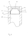
- FIG. 2 is a cross-sectional view of a portion of an insulated glass unit. With reference to FIGs. 1 and 2 , the IGU 10 includes a first pane of glass 12 and a second pane of glass 14. As shown in FIG. 2 , the panes are spaced apart in a substantially parallel relationship by a spacer 16. Between the panes 12, 14 and spacer 16 is an interpane space 18.
- the spacer 16 is formed of a metal such as aluminum or metal alloy tubing.
- the tubing can be provided in a variety of cross sectional configurations. It is noted that a variety of conventional spacer designs are commercially available from spacer manufacturers such as Allmetal and Homeshield.
- the spacer characteristically includes two generally opposed lateral surfaces 22 that are adapted to be bonded respectively to peripheral inner surfaces of the panes 12, 14. Bonding the spacer 16 to both panes desirably forms a gas-tight seal that prevents air and other gases from entering and exiting the interpane space 18.
- the sealing system of an IGU 10 desirably minimizes gas flow between the interpane space 18 and the ambient environment outside the IGU. While some IGUs have only a single seal, high performance units preferably have two seals, a primary or first seal 24 that is between the lateral surfaces 22 of the spacer 16 and the inner peripheral surfaces of the panes 12, 14 as represented by the dark line and a secondary or second seal 25.
- the first seal 24 is preferably formed of a material that is resistant to permeation of air, moisture and any insulative gas fill. For example, this seal can be advantageously formed of a butyl sealant (e.g., polyisobutylene).
- the second seal 25 is preferably formed of a material that has good adhesive properties.
- this seal can be formed of silicone, polysulfide, polyurethane, hot melt butyl, or any other material that bonds adhesively with the spacer and panes.
- the spacer 16 together with the first and second seals 24, 25 isolates the gaseous atmosphere within the interpane space from the ambient atmosphere exterior to the IGU.
- the interpane space of an IGU is preferably filled with an insulative gas.
- insulative gas is used herein to refer to any gas that is a better thermal insulator than air.
- argon is used which is commercially available from a number of suppliers.
- FIG. 3 illustrates generally a portion of a production line for manufacturing IGUs.
- the IGU 10 has a glass pane that is coated with a low emissivity coating, the coating is applied prior to assembly and need not be described in further detail.
- the glass panes are typically manually loaded onto conveyor 26 that transports the panes as well as partially assembled units to various stations for processing.
- the conveyor 26 may be comprised of a generally horizontal belt or other suitable solid surface to support the bottom surface of the glass or partially assembled units.
- a vertical platen 28 with a plurality rollers for vertical support and propulsion of the panes or partially formed assemblies propels the glass panes or partially formed assemblies through the production line.
- the glass panes may be conveyed to a variety of stations including, for example, an edge deletion station where, if present, coating on the glass is removed from the perimeter of the pane.
- the edge deleted glass pane may then be conveyed to a washing station to remove any debris or unwanted material from the surface of the pane.
- Pairs of panes, one pane with a spacer adhered thereto and a sealant deposited on the exposed surface of the spacer and a bare pane may be next conveyed to an assembly station (not shown) were the pairs are mated and joined together through the exposed sealant on the spacer.
- the partially assembled IGUs are then conveyed to a gas-fill station where typically a gas heavier than air is inserted into the interpane space and finally the unit is sealed.
- a gas-fill station typically a gas heavier than air is inserted into the interpane space and finally the unit is sealed.
- FIG. 4 is a perspective view of a measuring device 100, more particular a sparkunit which is part of the GasGlass device commercially offered by Sparklike, Ltd. of Finland.
- the measuring device 100 has a measuring end 102 which is placed against the IGU to be tested.
- a measurement button 104 is located on the device.
- FIG. 5 is a elevation view of the measuring end 102 of the measuring device shown in FIG. 4 .
- a metallic pin 106 extends out from the center of the device. Located just above the metallic pin 106 is an optical fiber sensor 108.
- the measuring end 102 of the device 100 is placed against an IGU that is being tested.
- the measurement button 104 is depressed which ignites a high voltage spark inside the IGU.
- the color of the spark is an indication of the amount of gas in the interpane space of the IGU.
- the optical fiber sensor108 picks up this color level and it is processed by a processing unit (not shown) of the GasGlass device and converted into a gas concentration reading, preferably as a percentage.
- FIG. 6 is a perspective schematic of an argon gas measuring station provided on an insulating glass unit production line.
- the GasGlass device measuring device 100 is mounted on an arm 136 which is securely positioned on the production line. As the IGU reaches the measuring device 100, the measuring device 100 is moved into contact with a surface of the glass and a spark test is conducted. In particular, the arm 136 has mechanics to extend and withdraw the measuring device 100 from the glass.
- a digital display (not shown) indicates the amount of argon as a percentage in the interpane space.
- the GasGlass device is not properly calibrated when it is delivered to the buyer or it may periodically need to be recalibrated. It is important to the productivity of the production line that calibration be possible on the production line. With the embodiments of the present invention, the GasGlass device can be regularly recalibrated.
- a plurality of calibration standard units i.e., standard IGUs
- One group of calibration standard units will have substantially identical construction, i.e. same thickness of panes, same distance between panes; but will be filled with different percentages of argon gas.
- Another group of calibration standard units will have substantially identical construction, i.e. same thickness of panes, same distance between panes, one or both of which will be different from the first group, and will also be filled with different percentages of argon gas.
- Preferably as many calibration standard units are made as types of IGUs that are made on the production line.
- a group of standard units will consist of seven calibration standard units with the following percentages of argon gas; 99%, 95%, 90%, 80%, 70%, 60% and 50%.
- the calibration standard units are filled with certified argon gas so that the precision of the argon content can be relied upon.
- FIG. 7 is a perspective view of a calibration standard unit 200 created according to a preferred embodiment of the present invention.
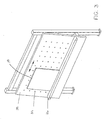
- the calibration standard unit has a first pane of glass 202, a second pane of glass 204, a spacer 206 located between the first and second panes of glass.
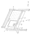
- the spacer 206 is a solid continuous piece of material, i.e. aluminum or stainless steel as seen in FIG. 9 . Using a solid spacer eliminates dead volume of gases that might dilute gas mixture over time and reduces the risk of gas loss that can occur with a spacer joint. In another embodiment shown in FIG.
- the spacer 306 has a small hole 308 with a plug 310 so that the interpane space of a calibration standard unit can be accessed.
- Sealants are previously described seal the panes of glass and spacer together.
- the interpane space is filled with a particular percentage of argon gas. This is done is a vacuum chamber. When the glass is held apart and nearly all atmosphere is removed, the argon gas mixture is flowed into the chamber and thus the air space cavity. When the air space is filled with desired gas, the glass slides are mechanically joined together with a spacer all while inside the vacuum chamber.
- the procedure of calibrating or recalibration the measurement unit will now be described.
- the calibration curve that matches the IGU being tested for example IGUs having pane thickness of 2 millimeters, is selected.
- the spark test is conducted and a reading is taken.
- the processing unit of the GasGlass device plots the reading on the selected calibration curve and maps a corresponding argon content reading which is displayed.
- a plurality of calibration standard units of insulating glass units that have substantially identical construction except that each calibration standard unit has a known, specific mixture of certified argon gas/air are prepared.
- the measurement device is aimed at a particular calibration standard unit and activated.
- a reading of the amount of argon in the particular calibration standard unit is taken. These steps are repeated for each of the calibration standard units. Calibration information is generated with the readings taken.
- the measuring device can be retested and, if necessary, recalibrated on the production line.
- the measuring device is aimed at a particular insulating glass unit produced on an assembly line and activated to take a reading of that unit.
- the measurement device is preferably removed from arm 136 and is aimed at that calibration standard unit and activated to take a reading of that unit.
- the measurement taken of the calibrated standard unit is compared with the known, specific amount of argon gas that the calibration standard unit has and the calibration of the measurement device is adjusted if the comparison taken of the measured calibration standard unit does not match the known amount of gas in the calibration standard unit.
- the spacer shown in Figure 9 is made of stainless steel and has a thickness, t, of about 0.5 inches.
- the spacer has a height, h, of about 13.5 inches and an overall width, w 1 , of about 9.5 inches.
- the width of each section of the pane, w 2 is about 0.5 inches.
- the radius of curvature, r 1 , of the spacer is about 0.5 inches.
- Figure 10 is a perspective view of a device 400 used to determine if the measurement device is generating sufficient power to conduct a spark test. It is important for the proper operation of the measurement unit that a sufficient amount of power be delivered to the unit so that a spark can be ignited in the interpane space.
- the method of testing a measurement unit consisted of laying a screwdriver on a table with the metal tip pointing away from the table. The measurement unit was aimed at the screwdriver's metal tip a certain distance as measured by a tape measure and the device was activated. It was determined at what distance the measurement device was not able to produce a spark that arced across to the screwdriver tip.
- the device shown in Figure 10 has a receiving end 402 for receiving the measuring end of the measurement device.
- a metal rod 404 that has a pointed tip 406 facing the receiving end 402 of the device 400.
- the pointed tip 406 is located about 1.575 inches from the metallic pin 106 of the measurement unit when it is mounted in the receiving end 402 of the device 400. It has been determined that if an arc can be produced between the metallic pin 106 and the pointed tip 406 of the rod 404 at that distance, the measurement, unit has sufficient power to properly conduct a spark test with an IGU. If an arc is not created, then the measure unit needs to be adjusted so that it delivers more power.
Landscapes
- Physics & Mathematics (AREA)
- Health & Medical Sciences (AREA)
- Pathology (AREA)
- Life Sciences & Earth Sciences (AREA)
- Chemical & Material Sciences (AREA)
- Analytical Chemistry (AREA)
- Biochemistry (AREA)
- General Health & Medical Sciences (AREA)
- General Physics & Mathematics (AREA)
- Immunology (AREA)
- Engineering & Computer Science (AREA)
- Nuclear Medicine, Radiotherapy & Molecular Imaging (AREA)
- Mathematical Physics (AREA)
- Theoretical Computer Science (AREA)
- Spectroscopy & Molecular Physics (AREA)
- Joining Of Glass To Other Materials (AREA)
- Investigating Or Analyzing Materials By The Use Of Electric Means (AREA)
- Glass Compositions (AREA)
- Sampling And Sample Adjustment (AREA)
- Other Investigation Or Analysis Of Materials By Electrical Means (AREA)
Claims (11)
- Kalibrationsstandardeinheit einer Isolierglaseinheit (10) mit einer bekannten Menge eines innerhalb eines Scheibenzwischenraums (18) enthaltenen Gases, wobei die Kalibrationsstandardeinheit Folgendes umfasst:eine erste Glasscheibe (12; 202);eine zweite Glasscheibe (14; 204) mit im Wesentlichen denselben Abmessungen wie die erste Glasscheibe (12; 202);einen Abstandshalter (16; 206; 306), der sich zwischen der ersten und der zweiten Glasscheibe (12, 14; 202, 204) befindet, wobei der Abstandshalter (16; 206; 306) um den Umfang der ersten und der zweiten Glasscheibe (12, 14; 202, 204) herum verläuft und der Scheibenzwischenraum (18) durch die erste und die zweite Scheibe (12, 14; 202, 204) und den Abstandshalter (16; 206; 306) aus einem massiven, kontinuierlichen Stück Material definiert wird, dadurch gekennzeichnet, dass der Abstandshalter (16; 206; 306) aus Aluminium oder Edelstahl gefertigt ist.
- Kalibrationsstandardeinheit nach Anspruch 1, wobei der Abstandshalter (16; 206; 306) eine Dicke im Bereich von ca. 0,250 Zoll bis ca. 0,875 Zoll (ca. 6,35 mm bis 22,2 mm) hat.
- Kalibrationsstandardeinheit nach einem der vorherigen Ansprüche, wobei das in dem Scheibenzwischenraum (18) enthaltene Gas Argon ist.
- Kalibrationsstandardeinheit nach Anspruch 3, wobei das Argon zertifiziertes Argon ist.
- Kalibrationsstandardeinheit nach einem der vorherigen Ansprüche, wobei der Prozentanteil des in dem Scheibenzwischenraum (18) enthaltenen Gases im Bereich von ca. 30% bis ca. 100%, vorzugsweise von ca. 50% bis ca. 100% liegt.
- Kalibrationsstandardeinheit nach einem der vorherigen Ansprüche, wobei die erste und die zweite Scheibe (12, 14; 202, 204) dieselbe Dicke haben.
- Kalibrationsstandardeinheit nach Anspruch 6, wobei die Dicke im Bereich von ca. 0,4 Zoll bis ca. 1,0 Zoll (ca. 10 mm bis 25 mm) liegt.
- Kalibrationsstandardeinheit nach einem der vorherigen Ansprüche, wobei der Abstandshalter (16; 206; 306) die erste und die zweite Scheibe (12, 14; 202, 204) um eine Distanz im Bereich von ca. 0,250 Zoll bis ca. 0,875 Zoll (ca. 6,35 mm bis 22,2 mm) voneinander trennt.
- Kalibrationsstandardeinheit nach einem der vorherigen Ansprüche, wobei die erste Glasscheibe (12; 202) mit einem Überzug mit niedrigem Emissionsvermögen beschichtet ist.
- Mehrere Kalibrationsstandardeinheiten einer Isolierglaseinheit (10) jeweils nach einem der vorherigen Ansprüche, wobei die Distanz, um die der Abstandshalter (16; 206; 306) die erste und die zweite Scheibe (12, 14; 202, 204) voneinander trennt, für jede der Kalibrationsstandardeinheiten im Wesentlichen gleich ist, und wobei die Dicke der ersten und der zweiten Glasscheibe für jede der Kalibrationsstandardeinheiten im Wesentlichen gleich ist.
- Mehrere Einheiten nach Anspruch 10, wobei die Menge an in einer Kalibrationsstandardeinheit (10) enthaltenem Gas in allen anderen Kalibrationsstandardeinheiten unterschiedlich ist.
Applications Claiming Priority (2)
| Application Number | Priority Date | Filing Date | Title |
|---|---|---|---|
| US10/610,160 US20040266013A1 (en) | 2003-06-30 | 2003-06-30 | Standard insulating glass units having known concentrations of a gas and methods for calibrating a measuring device using the standard insulating glass units |
| PCT/US2004/020746 WO2005005968A2 (en) | 2003-06-30 | 2004-06-28 | Standard insulating glass units having known concentrations of a gas and methods for calibrating a measuring device using the standard insulating glass units |
Publications (2)
| Publication Number | Publication Date |
|---|---|
| EP1639345A2 EP1639345A2 (de) | 2006-03-29 |
| EP1639345B1 true EP1639345B1 (de) | 2008-11-05 |
Family
ID=33541064
Family Applications (1)
| Application Number | Title | Priority Date | Filing Date |
|---|---|---|---|
| EP04777206A Expired - Lifetime EP1639345B1 (de) | 2003-06-30 | 2004-06-28 | Standardisolierglaseinheiten mit bekannten konzentrationen eines gases |
Country Status (8)
| Country | Link |
|---|---|
| US (3) | US20040266013A1 (de) |
| EP (1) | EP1639345B1 (de) |
| AT (1) | ATE413597T1 (de) |
| CA (1) | CA2530545A1 (de) |
| DE (1) | DE602004017610D1 (de) |
| DK (1) | DK1639345T3 (de) |
| ES (1) | ES2313073T3 (de) |
| WO (1) | WO2005005968A2 (de) |
Families Citing this family (8)
| Publication number | Priority date | Publication date | Assignee | Title |
|---|---|---|---|---|
| US7184146B2 (en) * | 2003-06-24 | 2007-02-27 | Cardinal Ig Company | Methods and apparatus for evaluating insulating glass units |
| US20040266013A1 (en) * | 2003-06-30 | 2004-12-30 | Erickson Gene P. | Standard insulating glass units having known concentrations of a gas and methods for calibrating a measuring device using the standard insulating glass units |
| US20070103686A1 (en) * | 2005-11-08 | 2007-05-10 | Niklas Tornkvist | Apparatus for non-invasive analysis of gas compositions in insulated glass panes |
| US8905085B2 (en) | 2011-09-09 | 2014-12-09 | Erdman Automation Corporation | Apparatus for edge sealing and simultaneous gas filling of insulated glass units |
| JP2014127543A (ja) * | 2012-12-26 | 2014-07-07 | Sony Corp | 冷却装置および半導体レーザ装置 |
| FR3029807B1 (fr) * | 2014-12-15 | 2016-12-30 | Laboratoire Nat De Metrologie Et D'essais | Enceinte de controle et d'etalonnage d'appareils de mesure du taux de gaz dans des vitrages isolants |
| JP6493379B2 (ja) * | 2016-05-19 | 2019-04-03 | Jfeスチール株式会社 | 金属スラブ清浄度の評価方法および金属スラブ清浄度の評価装置 |
| CN112818539B (zh) * | 2021-01-29 | 2022-11-15 | 中车青岛四方机车车辆股份有限公司 | 一种窗户的隔声设计方法及隔声设计系统 |
Citations (1)
| Publication number | Priority date | Publication date | Assignee | Title |
|---|---|---|---|---|
| EP0916801A2 (de) * | 1997-11-15 | 1999-05-19 | Dow Corning S.A. | Isolierverglasungen |
Family Cites Families (16)
| Publication number | Priority date | Publication date | Assignee | Title |
|---|---|---|---|---|
| US4859939A (en) * | 1987-12-21 | 1989-08-22 | The United States Of America As Represented By The Secretary Of The Army | Non-destructive testing of SOS wafers using surface photovoltage measurements |
| US4848138A (en) * | 1988-07-15 | 1989-07-18 | Marshall John M | Window gas monitor |
| US4939926A (en) * | 1989-06-05 | 1990-07-10 | The United States Of America As Represented By The Secretary Of The Navy | Apparatus and method for monitoring pressure leaks from a sealed system |
| US5196343A (en) * | 1990-10-04 | 1993-03-23 | Zerhouni Moustafa B | Ultrasonic calibration material and method |
| US5115668A (en) * | 1990-11-30 | 1992-05-26 | The United States Of America As Represented By The Secretary Of The Navy | Non-invasive pressure measuring device and method |
| CA2032912C (en) * | 1990-12-21 | 1994-06-28 | Bryan M. Latta | Nonintrusive gas-level measurement apparatus |
| US5439716A (en) * | 1992-03-19 | 1995-08-08 | Cardinal Ig Company | Multiple pane insulating glass unit with insulative spacer |
| FI98410C (fi) * | 1993-12-16 | 1997-06-10 | Instrumentarium Oy | Kaasuseosten analysointiin käytettävä mittausanturi ja mittausjärjestely |
| US5410402A (en) * | 1994-01-24 | 1995-04-25 | Seagate Technology, Inc. | Calibration standard for flying height tester having a wedge slider and a transparent disc held together |
| DE19505104A1 (de) * | 1995-02-15 | 1996-08-22 | Patent Treuhand Ges Fuer Elektrische Gluehlampen Mbh | Verfahren und Anordnung zur Bestimmung der Reinheit und/oder des Drucks von Gasen für elektrische Lampen |
| US5957169A (en) * | 1997-10-24 | 1999-09-28 | Cardinal Ig Company | Apparatus and method for filling insulated glass units with insulating gas |
| FI113805B (fi) * | 1998-04-03 | 2004-06-15 | Licentia Oy | Menetelmä ja laite kaasuseosten analysoimiseksi |
| US6397662B1 (en) * | 2000-02-16 | 2002-06-04 | Can-Best Building Sciences Corporation | Gas concentration meter and insulating glass assembly and method thereof |
| US6538238B1 (en) * | 2002-02-12 | 2003-03-25 | General Electric Company | Long term calibration of sensor assembly for glass-ceramic cooktop appliance |
| US7184146B2 (en) * | 2003-06-24 | 2007-02-27 | Cardinal Ig Company | Methods and apparatus for evaluating insulating glass units |
| US20040266013A1 (en) * | 2003-06-30 | 2004-12-30 | Erickson Gene P. | Standard insulating glass units having known concentrations of a gas and methods for calibrating a measuring device using the standard insulating glass units |
-
2003
- 2003-06-30 US US10/610,160 patent/US20040266013A1/en not_active Abandoned
-
2004
- 2004-06-28 AT AT04777206T patent/ATE413597T1/de not_active IP Right Cessation
- 2004-06-28 DK DK04777206T patent/DK1639345T3/da active
- 2004-06-28 CA CA002530545A patent/CA2530545A1/en not_active Abandoned
- 2004-06-28 WO PCT/US2004/020746 patent/WO2005005968A2/en not_active Ceased
- 2004-06-28 DE DE602004017610T patent/DE602004017610D1/de not_active Expired - Lifetime
- 2004-06-28 ES ES04777206T patent/ES2313073T3/es not_active Expired - Lifetime
- 2004-06-28 EP EP04777206A patent/EP1639345B1/de not_active Expired - Lifetime
-
2005
- 2005-12-23 US US11/317,642 patent/US20080184768A1/en not_active Abandoned
-
2008
- 2008-05-19 US US12/123,050 patent/US20090098317A1/en not_active Abandoned
Patent Citations (1)
| Publication number | Priority date | Publication date | Assignee | Title |
|---|---|---|---|---|
| EP0916801A2 (de) * | 1997-11-15 | 1999-05-19 | Dow Corning S.A. | Isolierverglasungen |
Also Published As
| Publication number | Publication date |
|---|---|
| ES2313073T3 (es) | 2009-03-01 |
| WO2005005968A3 (en) | 2005-07-21 |
| EP1639345A2 (de) | 2006-03-29 |
| DE602004017610D1 (de) | 2008-12-18 |
| WO2005005968A2 (en) | 2005-01-20 |
| DK1639345T3 (da) | 2009-02-23 |
| US20080184768A1 (en) | 2008-08-07 |
| US20040266013A1 (en) | 2004-12-30 |
| US20090098317A1 (en) | 2009-04-16 |
| CA2530545A1 (en) | 2005-01-20 |
| ATE413597T1 (de) | 2008-11-15 |
Similar Documents
| Publication | Publication Date | Title |
|---|---|---|
| US20090098317A1 (en) | Standard Insulating Glass Units Having Known Concentrations of a Gas and Methods for Calibrating a Measuring Device Using the Standard Insulating Glass Units | |
| US20070151209A1 (en) | Methods and apparatus for evaluating insulating glass units | |
| US8137494B2 (en) | Vacuum insulating glass unit with large pump-out port, and/or method of making the same | |
| EP2099997B1 (de) | Vakuum-isolierglasfenstereinheit mit metallelement in hermetischer kantendichtung | |
| CN111239062B (zh) | 气体定量检测设备及方法 | |
| US8683775B1 (en) | Spacer system for installing vacuum insulated glass (VIG) window unit in window frame designed to accommodate thicker IG window unit | |
| WO2001036827A3 (en) | Method of reliably detecting seal failures | |
| CN111417764A (zh) | 包括具有薄膜和毛细管的压力均衡体的隔热玻璃窗 | |
| US4395632A (en) | Cuvette for optical gas-analysis apparatus | |
| EP1630344A1 (de) | Verglasungsscheibe | |
| CN1118857C (zh) | 用于高压放电灯的氧扩散器 | |
| CN1734250A (zh) | 具有uv辐射源和辐射传感器的气候老化装置 | |
| EP3608941B1 (de) | Isotopenverhältnismessung | |
| GB1572978A (en) | Pneumatic infrared radiation detector with a vacuum-tight chamber and a radiation-permeable window | |
| US6795178B1 (en) | Method and apparatus for analysis of gas compositions | |
| KR102536949B1 (ko) | 가스 센서의 습도 보정 방법, 이를 이용한 가스 센서 및 자동식 소화기 | |
| US8302454B2 (en) | Method for calibrating a mass spectrometric sniffing leak detector | |
| CN101558466A (zh) | 放电管的充填气体压力的测定方法及放电管的制造方法 | |
| WO2006123935A1 (en) | Valve for double-glazed window | |
| JP2009002719A (ja) | 二次イオン質量分析装置に於ける試料ステージの傾斜角度較正方法及び二次イオン質量分析方法 | |
| Boese et al. | The 5nu3 Band of Carbon Dioxide-R Integrated Intensity. | |
| JPH06102180A (ja) | グロー放電分光分析装置 | |
| CN114295589A (zh) | 一种测定热熔胶光密度的方法 | |
| GB2176300A (en) | Method and apparatus for testing the stability of structural glazing sealed onto facade elements | |
| JPH07225187A (ja) | グロー放電発光分光分析用試料装着装置 |
Legal Events
| Date | Code | Title | Description |
|---|---|---|---|
| PUAI | Public reference made under article 153(3) epc to a published international application that has entered the european phase |
Free format text: ORIGINAL CODE: 0009012 |
|
| 17P | Request for examination filed |
Effective date: 20060102 |
|
| AK | Designated contracting states |
Kind code of ref document: A2 Designated state(s): AT BE BG CH CY CZ DE DK EE ES FI FR GB GR HU IE IT LI LU MC NL PL PT RO SE SI SK TR |
|
| 17Q | First examination report despatched |
Effective date: 20060721 |
|
| DAX | Request for extension of the european patent (deleted) | ||
| GRAP | Despatch of communication of intention to grant a patent |
Free format text: ORIGINAL CODE: EPIDOSNIGR1 |
|
| RTI1 | Title (correction) |
Free format text: STANDARD INSULATING GLASS UNITS HAVING KNOWN CONCENTRATIONS OF A GAS |
|
| GRAS | Grant fee paid |
Free format text: ORIGINAL CODE: EPIDOSNIGR3 |
|
| GRAA | (expected) grant |
Free format text: ORIGINAL CODE: 0009210 |
|
| AK | Designated contracting states |
Kind code of ref document: B1 Designated state(s): AT BE BG CH CY CZ DE DK EE ES FI FR GB GR HU IE IT LI LU MC NL PL PT RO SE SI SK TR |
|
| REG | Reference to a national code |
Ref country code: GB Ref legal event code: FG4D |
|
| REG | Reference to a national code |
Ref country code: CH Ref legal event code: EP Ref country code: CH Ref legal event code: NV Representative=s name: E. BLUM & CO. AG PATENT- UND MARKENANWAELTE VSP |
|
| REG | Reference to a national code |
Ref country code: IE Ref legal event code: FG4D |
|
| REF | Corresponds to: |
Ref document number: 602004017610 Country of ref document: DE Date of ref document: 20081218 Kind code of ref document: P |
|
| REG | Reference to a national code |
Ref country code: DK Ref legal event code: T3 |
|
| REG | Reference to a national code |
Ref country code: ES Ref legal event code: FG2A Ref document number: 2313073 Country of ref document: ES Kind code of ref document: T3 |
|
| PG25 | Lapsed in a contracting state [announced via postgrant information from national office to epo] |
Ref country code: AT Free format text: LAPSE BECAUSE OF FAILURE TO SUBMIT A TRANSLATION OF THE DESCRIPTION OR TO PAY THE FEE WITHIN THE PRESCRIBED TIME-LIMIT Effective date: 20081105 |
|
| PG25 | Lapsed in a contracting state [announced via postgrant information from national office to epo] |
Ref country code: SI Free format text: LAPSE BECAUSE OF FAILURE TO SUBMIT A TRANSLATION OF THE DESCRIPTION OR TO PAY THE FEE WITHIN THE PRESCRIBED TIME-LIMIT Effective date: 20081105 Ref country code: PL Free format text: LAPSE BECAUSE OF FAILURE TO SUBMIT A TRANSLATION OF THE DESCRIPTION OR TO PAY THE FEE WITHIN THE PRESCRIBED TIME-LIMIT Effective date: 20081105 |
|
| PG25 | Lapsed in a contracting state [announced via postgrant information from national office to epo] |
Ref country code: EE Free format text: LAPSE BECAUSE OF FAILURE TO SUBMIT A TRANSLATION OF THE DESCRIPTION OR TO PAY THE FEE WITHIN THE PRESCRIBED TIME-LIMIT Effective date: 20081105 Ref country code: BG Free format text: LAPSE BECAUSE OF FAILURE TO SUBMIT A TRANSLATION OF THE DESCRIPTION OR TO PAY THE FEE WITHIN THE PRESCRIBED TIME-LIMIT Effective date: 20090205 Ref country code: BE Free format text: LAPSE BECAUSE OF FAILURE TO SUBMIT A TRANSLATION OF THE DESCRIPTION OR TO PAY THE FEE WITHIN THE PRESCRIBED TIME-LIMIT Effective date: 20081105 Ref country code: RO Free format text: LAPSE BECAUSE OF FAILURE TO SUBMIT A TRANSLATION OF THE DESCRIPTION OR TO PAY THE FEE WITHIN THE PRESCRIBED TIME-LIMIT Effective date: 20081105 |
|
| PG25 | Lapsed in a contracting state [announced via postgrant information from national office to epo] |
Ref country code: PT Free format text: LAPSE BECAUSE OF FAILURE TO SUBMIT A TRANSLATION OF THE DESCRIPTION OR TO PAY THE FEE WITHIN THE PRESCRIBED TIME-LIMIT Effective date: 20090406 Ref country code: CZ Free format text: LAPSE BECAUSE OF FAILURE TO SUBMIT A TRANSLATION OF THE DESCRIPTION OR TO PAY THE FEE WITHIN THE PRESCRIBED TIME-LIMIT Effective date: 20081105 Ref country code: SE Free format text: LAPSE BECAUSE OF FAILURE TO SUBMIT A TRANSLATION OF THE DESCRIPTION OR TO PAY THE FEE WITHIN THE PRESCRIBED TIME-LIMIT Effective date: 20090205 |
|
| PLBE | No opposition filed within time limit |
Free format text: ORIGINAL CODE: 0009261 |
|
| STAA | Information on the status of an ep patent application or granted ep patent |
Free format text: STATUS: NO OPPOSITION FILED WITHIN TIME LIMIT |
|
| PG25 | Lapsed in a contracting state [announced via postgrant information from national office to epo] |
Ref country code: SK Free format text: LAPSE BECAUSE OF FAILURE TO SUBMIT A TRANSLATION OF THE DESCRIPTION OR TO PAY THE FEE WITHIN THE PRESCRIBED TIME-LIMIT Effective date: 20081105 |
|
| 26N | No opposition filed |
Effective date: 20090806 |
|
| PG25 | Lapsed in a contracting state [announced via postgrant information from national office to epo] |
Ref country code: MC Free format text: LAPSE BECAUSE OF NON-PAYMENT OF DUE FEES Effective date: 20090630 |
|
| REG | Reference to a national code |
Ref country code: FR Ref legal event code: ST Effective date: 20100226 |
|
| REG | Reference to a national code |
Ref country code: IE Ref legal event code: MM4A |
|
| PG25 | Lapsed in a contracting state [announced via postgrant information from national office to epo] |
Ref country code: IE Free format text: LAPSE BECAUSE OF NON-PAYMENT OF DUE FEES Effective date: 20090628 Ref country code: FR Free format text: LAPSE BECAUSE OF NON-PAYMENT OF DUE FEES Effective date: 20090630 |
|
| PG25 | Lapsed in a contracting state [announced via postgrant information from national office to epo] |
Ref country code: GR Free format text: LAPSE BECAUSE OF FAILURE TO SUBMIT A TRANSLATION OF THE DESCRIPTION OR TO PAY THE FEE WITHIN THE PRESCRIBED TIME-LIMIT Effective date: 20090206 |
|
| PG25 | Lapsed in a contracting state [announced via postgrant information from national office to epo] |
Ref country code: IT Free format text: LAPSE BECAUSE OF FAILURE TO SUBMIT A TRANSLATION OF THE DESCRIPTION OR TO PAY THE FEE WITHIN THE PRESCRIBED TIME-LIMIT Effective date: 20081105 |
|
| PG25 | Lapsed in a contracting state [announced via postgrant information from national office to epo] |
Ref country code: LU Free format text: LAPSE BECAUSE OF NON-PAYMENT OF DUE FEES Effective date: 20090628 |
|
| PG25 | Lapsed in a contracting state [announced via postgrant information from national office to epo] |
Ref country code: HU Free format text: LAPSE BECAUSE OF FAILURE TO SUBMIT A TRANSLATION OF THE DESCRIPTION OR TO PAY THE FEE WITHIN THE PRESCRIBED TIME-LIMIT Effective date: 20090506 |
|
| PG25 | Lapsed in a contracting state [announced via postgrant information from national office to epo] |
Ref country code: TR Free format text: LAPSE BECAUSE OF FAILURE TO SUBMIT A TRANSLATION OF THE DESCRIPTION OR TO PAY THE FEE WITHIN THE PRESCRIBED TIME-LIMIT Effective date: 20081105 |
|
| PG25 | Lapsed in a contracting state [announced via postgrant information from national office to epo] |
Ref country code: CY Free format text: LAPSE BECAUSE OF FAILURE TO SUBMIT A TRANSLATION OF THE DESCRIPTION OR TO PAY THE FEE WITHIN THE PRESCRIBED TIME-LIMIT Effective date: 20081105 |
|
| PGFP | Annual fee paid to national office [announced via postgrant information from national office to epo] |
Ref country code: FI Payment date: 20190627 Year of fee payment: 16 Ref country code: NL Payment date: 20190626 Year of fee payment: 16 Ref country code: DK Payment date: 20190627 Year of fee payment: 16 |
|
| PGFP | Annual fee paid to national office [announced via postgrant information from national office to epo] |
Ref country code: ES Payment date: 20190701 Year of fee payment: 16 Ref country code: GB Payment date: 20190627 Year of fee payment: 16 Ref country code: DE Payment date: 20190627 Year of fee payment: 16 |
|
| PGFP | Annual fee paid to national office [announced via postgrant information from national office to epo] |
Ref country code: CH Payment date: 20190702 Year of fee payment: 16 |
|
| REG | Reference to a national code |
Ref country code: DE Ref legal event code: R119 Ref document number: 602004017610 Country of ref document: DE |
|
| REG | Reference to a national code |
Ref country code: FI Ref legal event code: MAE |
|
| REG | Reference to a national code |
Ref country code: DK Ref legal event code: EBP Effective date: 20200630 |
|
| PG25 | Lapsed in a contracting state [announced via postgrant information from national office to epo] |
Ref country code: FI Free format text: LAPSE BECAUSE OF NON-PAYMENT OF DUE FEES Effective date: 20200628 |
|
| REG | Reference to a national code |
Ref country code: CH Ref legal event code: PL |
|
| REG | Reference to a national code |
Ref country code: NL Ref legal event code: MM Effective date: 20200701 |
|
| GBPC | Gb: european patent ceased through non-payment of renewal fee |
Effective date: 20200628 |
|
| PG25 | Lapsed in a contracting state [announced via postgrant information from national office to epo] |
Ref country code: GB Free format text: LAPSE BECAUSE OF NON-PAYMENT OF DUE FEES Effective date: 20200628 Ref country code: NL Free format text: LAPSE BECAUSE OF NON-PAYMENT OF DUE FEES Effective date: 20200701 Ref country code: CH Free format text: LAPSE BECAUSE OF NON-PAYMENT OF DUE FEES Effective date: 20200630 Ref country code: LI Free format text: LAPSE BECAUSE OF NON-PAYMENT OF DUE FEES Effective date: 20200630 |
|
| PG25 | Lapsed in a contracting state [announced via postgrant information from national office to epo] |
Ref country code: DE Free format text: LAPSE BECAUSE OF NON-PAYMENT OF DUE FEES Effective date: 20210101 |
|
| PG25 | Lapsed in a contracting state [announced via postgrant information from national office to epo] |
Ref country code: DK Free format text: LAPSE BECAUSE OF NON-PAYMENT OF DUE FEES Effective date: 20200630 |
|
| PG25 | Lapsed in a contracting state [announced via postgrant information from national office to epo] |
Ref country code: ES Free format text: LAPSE BECAUSE OF NON-PAYMENT OF DUE FEES Effective date: 20200629 |