EP1638773B1 - Method for operating an inking system - Google Patents
Method for operating an inking system Download PDFInfo
- Publication number
- EP1638773B1 EP1638773B1 EP04733573A EP04733573A EP1638773B1 EP 1638773 B1 EP1638773 B1 EP 1638773B1 EP 04733573 A EP04733573 A EP 04733573A EP 04733573 A EP04733573 A EP 04733573A EP 1638773 B1 EP1638773 B1 EP 1638773B1
- Authority
- EP
- European Patent Office
- Prior art keywords
- inking
- cylinder
- roller
- ink
- speed
- Prior art date
- Legal status (The legal status is an assumption and is not a legal conclusion. Google has not performed a legal analysis and makes no representation as to the accuracy of the status listed.)
- Not-in-force
Links
Images

Classifications
-
- B—PERFORMING OPERATIONS; TRANSPORTING
- B41—PRINTING; LINING MACHINES; TYPEWRITERS; STAMPS
- B41F—PRINTING MACHINES OR PRESSES
- B41F31/00—Inking arrangements or devices
- B41F31/15—Devices for moving vibrator-rollers
-
- B—PERFORMING OPERATIONS; TRANSPORTING
- B41—PRINTING; LINING MACHINES; TYPEWRITERS; STAMPS
- B41F—PRINTING MACHINES OR PRESSES
- B41F31/00—Inking arrangements or devices
-
- B—PERFORMING OPERATIONS; TRANSPORTING
- B41—PRINTING; LINING MACHINES; TYPEWRITERS; STAMPS
- B41F—PRINTING MACHINES OR PRESSES
- B41F33/00—Indicating, counting, warning, control or safety devices
- B41F33/04—Tripping devices or stop-motions
- B41F33/10—Tripping devices or stop-motions for starting or stopping operation of damping or inking units
-
- B—PERFORMING OPERATIONS; TRANSPORTING
- B41—PRINTING; LINING MACHINES; TYPEWRITERS; STAMPS
- B41P—INDEXING SCHEME RELATING TO PRINTING, LINING MACHINES, TYPEWRITERS, AND TO STAMPS
- B41P2233/00—Arrangements for the operation of printing presses
- B41P2233/10—Starting-up the machine
- B41P2233/11—Pre-inking
Definitions
- the invention relates to a method for operating an inking unit according to the preamble of claim 1.
- An inking unit is for example from the WO 98/51500 A1 known.
- this inking unit there are two color roller trains with which, independently of one another, color can be transferred from a central roller to a forme cylinder. The ink is thereby removed on the one hand by means of an inking roller from the central roller and transferred to the forme cylinder.
- two inking rollers each are present in the inking roller train, which likewise remove ink from the central roller and transfer it to the inking roller via a rider roller.
- the form cylinder in turn, which carries the printing plates, can be employed on a blanket cylinder, for example a blanket cylinder, in order to print in this way a printing material web running along the blanket cylinder in offset printing.
- the various rollers of the inking unit, the forme cylinder and the blanket cylinder are brought into contact with each other and then accelerated together.
- the inking device is set in motion, for example by switching on a paint pump.
- the inking unit, the forme cylinder and the blanket cylinder is colored, at the same time decreases the printing material on the blanket cylinder color.
- a disadvantage of this process for inking the inking unit on a rotary printing press is that considerable amounts of the printing material web are consumed during the startup process required for inking the various rollers, which must then be disposed of as waste. Both by the Consumption of the printing material as well as their disposal are causing considerable costs.
- the DE 101 11 363 A1 describes a printing unit for the flying plate change, wherein an inking unit is selectively employed on one or the other plate cylinder.
- the DE 40 13 740 C2 discloses a printing unit in which are separated for pre-inking plate cylinder and blanket cylinder.
- the inking rollers are preferably employed for running in the ink on the plate cylinder, but can also be temporarily switched.
- the DE 101 29 555 A1 describes a method for doubling-reducing control of a printing press, in which the order of the Zylinderan- or shutdown is determined.
- the DE 100 46 371 A1 discloses a method for pre-inking an inking unit, wherein a forme cylinder and / or a roller of the inking unit have a pre-inking speed.
- the invention has for its object to provide a method for operating an inking unit.
- the newly proposed method is based on the idea that the various inked during startup of the printing press rolls gradually be colored.
- a phase of pre-inking is proposed, during which at least the rollers of the inking unit are inked with printing ink, without the ink being conveyed on to the printing material web via the blanket cylinder.
- the form cylinder of the printing unit during Voreinfärbens from Blanket cylinder off, so that the ink can not be conveyed beyond the form cylinder addition.
- at least the rollers of the inking unit are driven in rotation and pre-colored by ink application by means of the inking device.
- the form cylinder is also pre-colored at the same time as the rollers of the inking unit.
- the forme cylinder is not in contact with the rollers of the inking unit during certain phases of the pre-inking or during the entire pre-inking of the inking unit.
- At least two phases are provided during the pre-inking.
- the inking rollers of the inking unit which transfer the ink from the inking unit to the forme cylinder, are offset from the forme cylinder so that in this first phase only the rollers of the inking unit itself are pre-dyed.
- the inking rollers of the inking unit are employed on the forme cylinder and pre-colored at synchronous speed by ink transfer of the ink from the inking rollers.
- the rollers of the inking unit and the forme cylinder are sufficiently supplied with printing ink.
- the speed is just to choose so that the peripheral speed of the blanket cylinder corresponds to the peripheral speed of the forme cylinder.
- the blanket cylinder is brought into engagement with the forme cylinder so that the ink can be transferred from the forme cylinder to the blanket cylinder.
- the blanket cylinder with the printing substrate, with synchronous web speed, are brought into contact, so that the offset printing process on the printing material begins. Due to the already pre-inked rollers of the inking unit or due to the pre-inked forme cylinder significantly less substrate web is required as waste until a print image with sufficient print quality is reached.
- the rollers of the inking unit or the forme cylinder should circulate during the pre-inking about 20 to 150 revolutions. This number of revolutions is usually sufficient to form a sufficient ink film on the rollers of the inking unit or the forme cylinder.
- a specific speed profile of the rollers of the inking unit or of the forme cylinder is traversed.
- the rollers of the inking unit or of the forme cylinders can be accelerated to a pre-inking speed.
- This Voreinfärbe für may preferably be chosen such that it the speed of the rollers of the inking unit at 150 to 250 revolutions / min. in particular about 180 to 200 revolutions / min.
- the rollers of the inking unit and the forme cylinder are decelerated from the pre-inking rate to the setting speed before the synchronously rotating blanket cylinder is set against the forme cylinder.
- the rollers of the inking unit, the forme cylinder and the blanket cylinder can then be accelerated together to the intended printing speed.
- a setting speed a speed has been found that corresponds to a peripheral speed of 4 to 8 m / min, in particular about 6 m / min
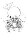
- An inking 01, z. B. a short inking unit 01 for a rotary printing press consists essentially of an inking device 03, which emits an ink application to a color pickup roller 02 (hereinafter referred to as the central roller 02 or roller 02).
- central roller 02 With the central roller 02 are one or more rollers 12; 13, z. B. inking rollers 12; 13 in touch.
- the inking device 03 may, for. B. from a known chambered doctor blade 03 but also consist of several mutually contacting rollers, the color application z. B. from a conventional paint box or a pump or Farbaufsprüh Nur, etc. obtained.
- One or more color roller trains can be provided.
- rollers of other construction can be used.
- the ceramic or glass cladding can also be screened or have a surface structure produced in a different way.
- With the shell of the roller 02 is in addition to the inking device 03 and the inking rollers 12; 13 at least one roller 16 or 17, z. B. ink roller 16 or 17 with oleophilem coat in contact.
- With the inking rollers 12; 13 and each of the ink roller 16; 17 is a first roller 29 and 31, z. B. a first anilox roller 29 and 31 with their oleophilic coat in touch.
- inking rollers 12; 13 even more rider rollers with oleophilem coat can be placed, which in Fig. 1 are not shown.
- the ink rollers 16; 17 are on the roller 02 on and off. It is sufficient, the rollers 12; 13; 16; 17; 29; 31 and possibly further provided rollers to drive by friction. But they can also be driven in other ways, eg. B. by electric drives. They are each adjustable to their adjacent rollers or in addition to the roller 02, thereby being able to influence the width of the ink transfer strip.
- the upper rollers 12; 29; 16 form a first inking roller train 20.
- the lower inking rollers 13; 31; 17 form a second color roller train 25.
- These two color roller trains 20; 25 are respectively from the central roller 02 via the respective first ink rollers 16; 17 and additionally on the inking rollers 12; 13 fed with ink.
- the rollers 12; 29; 16 of the first color roller train 20 are pivotally arranged together about the axis of rotation 10 of the roller 02.
- rollers 13; 31; 17 of the second ink roller train 25 are pivotally mounted together about the axis of rotation 10 of the roller 02.
- rollers 12; 29; 16, 13; 31; 17 both color roller trains 20; 25 are so far pivoted about the axis of rotation 10 from its working position A from the forme cylinder 11 that they can come from an approximately horizontal position in a nearly vertical position. They are independent of each other and reasonably movable one after the other.
- the inking device 03 is to be removed from the inking unit 01. This creates space for temporary access to the rollers 12; 29; 16 of the first color roller train 20 or the rollers 13; 31; 17 of the second color roller train 25.
- the diameter of the central roller 02 may be equal to, larger or smaller than the diameter of the rollers 12; 29; 16 and 13, respectively; 31; 17 be. It corresponds to a non-integer multiple of the aforementioned rollers 12; 13; 16; 17; 29; 31.
- the aforementioned rollers 12; 13; 16; 17; 29; 31 may all have different diameters from each other.
- the two roll pin 18; 33; 21 and 19, respectively; 34; 22 of the rollers 12; 29; 16 or 13; 31; 17 and possibly additional rollers are in guides 23; 06; 26 and 24, respectively; 07; 27 arranged and against spring 28, z.
- the guides 23; 06; 26 and 24, respectively; 07; 27 are each in both oscillators 08; 09 provided.
- a blanket cylinder 60 which may be formed in particular in the manner of a blanket cylinder 60, are employed.
- the printed image can be transferred from the forme cylinder 11 to the blanket cylinder 60.
- the blanket cylinder 60 in turn can be attached to a printing material web, for example a paper web, in Fig. 1 not shown, come to rest in order to transfer in this way the printed image on the substrate web.
- the inking device 03 is set at time t 1 in operation to print in this way D or E of the To transfer inking device 03 on the roller 02 of the inking unit 01 and in this way these rollers 02, 12; 13; 16; 17; 29; 31 to pre-color together.
- the single drive of the forme cylinder 11 is set in motion and accelerated linearly to a peripheral speed corresponding to the Voreinfärbe york V 1 .
- the forme cylinder 11 has reached the Voreinfärbe Anthony V 1 and thus with synchronous peripheral speed relative to the inking rollers 12; 13 rotates, the forme cylinder 11 at time t 2 to the inking rollers 12; 13 employed, so that the printing ink D or E of the inking rollers 12; 13 is transferred to the forme cylinder 11 to pre-inking this.
- the blanket cylinder 60 is accelerated by the dedicated single drive to the Anstellica V 2 .
- the blanket cylinder 60 and the die cylinder 11 rotate at synchronous peripheral velocity of, for example, 6 m / min, the blanket cylinder 60 is at the time t against the forme cylinder 11, 3, so that a running on the blanket cylinder 60 print substrate web is printed.
- the rollers are 02; 12; 13; 16; 17; 29; 31 of the inking unit 01, the forme cylinder 11 and the blanket cylinder 60 are accelerated together to the desired printing speed. From the time t 4 then the printing material web is printed with sufficient quality.
- the Voreinfärbe Alfa V 1 results from a speed of the forme cylinder 11 of 6000 to 14000 U / h, in particular 8000 to 12000 U / h and / or is 6000 to 14000 m / h, in particular 8000 to 12000 m / h.
- the setting speed (V 2 ) is smaller than the Voreinfärbe Anlagen (V 1 ) and corresponds to 0m / min or 4 to 8m / min, in particular about 6m / min.
- the production speed is higher than the pitch.
- the inking unit 01 is rotatively driven by its own motor and has no positive connection to the forme cylinder 11th
- Form cylinder 11 and blanket cylinder 60 are driven by their own position-controlled motors, these cylinders are not for rotary drive in positive drive connection.
Abstract
Description
Die Erfindung betrifft ein Verfahren zum Betrieb eines Farbwerks gemäß dem Oberbegriff des Anspruches 1.The invention relates to a method for operating an inking unit according to the preamble of claim 1.
Ein Farbwerk ist beispielsweise aus der
Beim Anfahren solcher Druckmaschinen werden die verschiedenen Walzen des Farbwerkes, der Formzylinder und der Drucktuchzylinder miteinander in Kontakt gebracht und anschließend gemeinsam beschleunigt. Sobald die verschiedenen Walzen und Zylinder eine bestimmte Umlaufgeschwindigkeit erreicht haben, wird die Farbauftragseinrichtung in Gang gesetzt, beispielsweise durch Einschalten einer Farbpumpe. Auf diese Weise wird dann das Farbwerk, der Formzylinder und der Drucktuchzylinder eingefärbt, wobei zugleich die Bedruckstoffbahn am Drucktuchzylinder Farbe abnimmt. Nachteilig an diesem Verfahren zum Einfärben des Farbwerks an einer Rotationsdruckmaschine ist es, dass während des zum Einfärben der verschiedenen Walzen erforderlichen Anfahrprozesses erhebliche Mengen der Bedruckstoffbahn verbraucht werden, die anschließend als Abfall entsorgt werden muss. Sowohl durch den Verbrauch der Bedruckstoffbahn als auch durch deren Entsorgung werden erhebliche Kosten verursacht.When starting such printing presses, the various rollers of the inking unit, the forme cylinder and the blanket cylinder are brought into contact with each other and then accelerated together. Once the various rollers and cylinders have reached a certain rotational speed, the inking device is set in motion, for example by switching on a paint pump. In this way, then the inking unit, the forme cylinder and the blanket cylinder is colored, at the same time decreases the printing material on the blanket cylinder color. A disadvantage of this process for inking the inking unit on a rotary printing press is that considerable amounts of the printing material web are consumed during the startup process required for inking the various rollers, which must then be disposed of as waste. Both by the Consumption of the printing material as well as their disposal are causing considerable costs.
Die
Die
Durch die
Die
Die
Der Erfindung liegt die Aufgabe zugrunde, ein Verfahren zum Betrieb eines Farbwerks zu schaffen.The invention has for its object to provide a method for operating an inking unit.
Die Aufgabe wird erfindungsgemäß durch die Merkmale des Anspruches 1 gelöst.The object is achieved by the features of claim 1.
Das neu vorgeschlagene Verfahren beruht auf dem Grundgedanken, dass die verschiedenen beim Anfahren der Druckmaschine einzufärbenden Walzen stufenweise eingefärbt werden. Es wird dazu eine Phase des Voreinfärbens vorgeschlagen, während der zumindest die Walzen des Farbwerkes mit Druckfarbe eingefärbt werden, ohne dass die Druckfarbe über den Drucktuchzylinder an die Bedruckstoffbahn weitergefördert wird. Dazu wird der Formzylinder des Druckwerkes während des Voreinfärbens vom Drucktuchzylinder abgestellt, so dass die Druckfarbe nicht über den Formzylinder hinaus weitergefördert werden kann. Während des eigentlichen Voreinfärbens werden zumindest die Walzen des Farbwerkes rotierend angetrieben und durch Farbauftrag mittels der Farbauftrageinrichtung voreingefärbt. Grundsätzlich ist es dabei denkbar, dass auch der Formzylinder zugleich mit den Walzen des Farbwerkes voreingefärbt wird. Alternativ bzw. additiv dazu ist es auch denkbar, dass der Formzylinder während bestimmter Phasen des Voreinfärbens bzw. während des gesamten Voreinfärbens des Farbwerkes nicht mit den Walzen des Farbwerkes in Kontakt steht.The newly proposed method is based on the idea that the various inked during startup of the printing press rolls gradually be colored. For this purpose, a phase of pre-inking is proposed, during which at least the rollers of the inking unit are inked with printing ink, without the ink being conveyed on to the printing material web via the blanket cylinder. For this purpose, the form cylinder of the printing unit during Voreinfärbens from Blanket cylinder off, so that the ink can not be conveyed beyond the form cylinder addition. During the actual pre-inking, at least the rollers of the inking unit are driven in rotation and pre-colored by ink application by means of the inking device. In principle, it is conceivable that the form cylinder is also pre-colored at the same time as the rollers of the inking unit. Alternatively or in addition thereto, it is also conceivable that the forme cylinder is not in contact with the rollers of the inking unit during certain phases of the pre-inking or during the entire pre-inking of the inking unit.
Nach einer bevorzugten Verfahrensvariante sind während des Voreinfärbens zumindest zwei Phasen vorgesehen. In der ersten Phase des Voreinfärbens sind die Farbauftragswalzen des Farbwerkes, die die Farbe vom Farbwerk auf den Formzylinder übertragen, vom Formzylinder abgestellt, so dass in dieser ersten Phase nur die Walzen des Farbwerks selbst voreingefärbt werden. In der zweiten Phase des Voreinfärbens werden dann die Farbauftragswalzen des Farbwerkes an den Formzylinder angestellt und bei synchroner Drehzahl durch Farbübertragung der Druckfarbe von den Farbauftragswalzen mit voreingefärbt. Nach Ende der zweiten Phase des Voreinfärbens sind die Walzen des Farbwerkes und der Formzylinder ausreichend mit Druckfarbe versorgt.According to a preferred variant of the method, at least two phases are provided during the pre-inking. In the first phase of the pre-inking, the inking rollers of the inking unit, which transfer the ink from the inking unit to the forme cylinder, are offset from the forme cylinder so that in this first phase only the rollers of the inking unit itself are pre-dyed. In the second phase of Voreinfärss then the inking rollers of the inking unit are employed on the forme cylinder and pre-colored at synchronous speed by ink transfer of the ink from the inking rollers. After the second phase of the pre-inking, the rollers of the inking unit and the forme cylinder are sufficiently supplied with printing ink.
Zum Anfahren der Druckmaschine ist es nach Ende des Voreinfärbens erforderlich den Drucktuchzylinder auf eine synchrone Drehzahl mit dem Formzylinder zu beschleunigen, wobei die Drehzahl grade so zu wählen ist, dass die Umfangsgeschwindigkeit des Drucktuchzylinders der Umfangsgeschwindigkeit des Formzylinders entspricht. Anschließend wird der Drucktuchzylinder mit dem Formzylinder in Eingriff gebracht, so dass die Druckfarbe vom Formzylinder auf den Drucktuchzylinder übertragen werden kann.To start the printing press, it is after the pre-inking required to accelerate the blanket cylinder to a synchronous speed with the forme cylinder, the speed is just to choose so that the peripheral speed of the blanket cylinder corresponds to the peripheral speed of the forme cylinder. Subsequently, the blanket cylinder is brought into engagement with the forme cylinder so that the ink can be transferred from the forme cylinder to the blanket cylinder.
Anschließend kann dann der Drucktuchzylinder mit der Bedruckstoffbahn, die mit synchroner Bahngeschwindigkeit abläuft, in Kontakt gebracht werden, so dass der Offset-Druckvorgang auf der Bedruckstoffbahn beginnt. Aufgrund der bereits voreingefärbten Walzen des Farbwerkes bzw. aufgrund des voreingefärbten Formzylinders wird erheblich weniger Bedruckstoffbahn als Makulatur benötigt, bis ein Druckbild mit ausreichender Druckqualität erreicht ist.Then then the blanket cylinder with the printing substrate, with synchronous web speed, are brought into contact, so that the offset printing process on the printing material begins. Due to the already pre-inked rollers of the inking unit or due to the pre-inked forme cylinder significantly less substrate web is required as waste until a print image with sufficient print quality is reached.
Nach einer bevorzugten Ausführungsform der Erfindung sollten die Walzen des Farbwerkes bzw. der Formzylinder während des Voreinfärbens ungefähr 20 bis 150 Umdrehungen umlaufen. Diese Anzahl von Umdrehungen ist in der Regel ausreichend um einen ausreichenden Farbfilm auf den Walzen des Farbwerkes bzw. dem Formzylinder zu bilden.According to a preferred embodiment of the invention, the rollers of the inking unit or the forme cylinder should circulate during the pre-inking about 20 to 150 revolutions. This number of revolutions is usually sufficient to form a sufficient ink film on the rollers of the inking unit or the forme cylinder.
Besonders vorteilhaft ist es, wenn während des Voreinfärbens ein bestimmtes Geschwindigkeitsprofil der Walzen des Farbwerkes bzw. des Formzylinders abgefahren wird. Während des Voreinfärbens können die Walzen des Farbwerkes bzw. der Formzylinder bis zu einer Voreinfärbegeschwindigkeit beschleunigt werden. Diese Voreinfärbegeschwindigkeit kann vorzugsweise derart gewählt werden, dass sie der Drehzahl der Walzen des Farbwerkes bei 150 bis 250 Umdrehungen/min. insbesondere ungefähr 180 bis 200 Umdrehungen/min, entspricht. Nach ausreichender Voreinfärbung werden die Walzen des Farbwerkes und der Formzylinder von der Voreinfärbegeschwindigkeit auf Anstellgeschwindigkeit abgebremst, bevor der synchron rotierende Drucktuchzylinder an den Formzylinder angestellt wird. Anschließend können die Walzen des Farbwerkes, der Formzylinder und der Drucktuchzylinder dann gemeinsam auf die vorgesehene Druckgeschwindigkeit beschleunigt werden. Als Anstellgeschwindigkeit hat sich eine Geschwindigkeit bewährt, die einer Umfangsgeschwindigkeit von 4 bis 8 m/min, insbesondere ungefähr 6 m/min entsprichtIt is particularly advantageous if, during the pre-inking, a specific speed profile of the rollers of the inking unit or of the forme cylinder is traversed. During pre-inking, the rollers of the inking unit or of the forme cylinders can be accelerated to a pre-inking speed. This Voreinfärbegeschwindigkeit may preferably be chosen such that it the speed of the rollers of the inking unit at 150 to 250 revolutions / min. in particular about 180 to 200 revolutions / min. After sufficient pre-inking, the rollers of the inking unit and the forme cylinder are decelerated from the pre-inking rate to the setting speed before the synchronously rotating blanket cylinder is set against the forme cylinder. Subsequently, the rollers of the inking unit, the forme cylinder and the blanket cylinder can then be accelerated together to the intended printing speed. As a setting speed, a speed has been found that corresponds to a peripheral speed of 4 to 8 m / min, in particular about 6 m / min
Besonders bewährt hat sich das neu vorgeschlagene Verfahren zum Voreinfärben der Walzen des Farbwerkes bzw. des Formzylinders, wenn im sogenannten Trockenoffset gearbeitet wird, d. h. wenn die Druckfarbe ohne zusätzliches Feuchtmittel, insbesondere ohne zusätzliches Wasser, verarbeitet wird.Has proven particularly useful the newly proposed method for pre-inking the rollers of the inking unit or of the forme cylinder, if in so-called dry offset is worked, ie when the ink without additional dampening solution, especially without additional water, is processed.
Ein Ausführungsbeispiel der Erfindung ist in den Zeichnungen dargestellt und wird im folgenden näher beschrieben.An embodiment of the invention is illustrated in the drawings and will be described in more detail below.
Es zeigen:
- Fig. 1
- eine Seitenansicht eines schematisch dargestellten Farbwerks;
- Fig. 2
- das Geschwindigkeitsprofil verschiedener Walzen und Zylinder des in
Fig. 1 dargestellten Farbwerkes während des Voreinfärbens.
- Fig. 1
- a side view of a schematically illustrated inking unit;
- Fig. 2
- the speed profile of various rollers and cylinders of the in
Fig. 1 illustrated inking unit during pre-inking.
Ein Farbwerk 01, z. B. ein Kurzfarbwerk 01 für eine Rotationsdruckmaschine, besteht im Wesentlichen aus einer Farbauftragseinrichtung 03, die einen Farbauftrag an eine Farbaufnahmewalze 02 abgibt (im Folgenden kurz zentrale Walze 02 oder Walze 02 genannt).An
Mit der zentralen Walze 02 stehen eine oder mehrere Walzen 12; 13, z. B. Farbauftragswalzen 12; 13 in Berührung.With the
Die Farbauftragseinrichtung 03 kann z. B. aus einer an sich bekannten Kammerrakel 03 aber auch aus mehreren miteinander in Berührung stehenden Walzen bestehen, die ihren Farbauftrag z. B. von einem herkömmlichen Farbkasten oder einem Pump- oder einer Farbaufsprüheinrichtung usw. erhalten. Es können ein oder mehrere Farbwalzenzüge vorgesehen werden.The inking
Ist die zentrale Walze 02, z. B. als Rasterwalze 02 ausgebildet, so wird mit ihren Näpfchen bzw. Haschuren Druckfarbe transportiert.Is the
Anstatt der Rasterwalze 02 können aber auch Walzen anderer Konstruktion in Anwendung kommen. Sie können z. B. einen glatten Kunststoff-Mantel oder einen anderen oleophilen, gummielastischen Mantel oder einen Keramikmantel oder einen Mantel aus Glas aufweisen. Der Keramik- oder Glasmantel kann auch gerastert sein oder eine auf andere Art hergestellte Oberflächenstruktur haben. Mit dem Mantel der Walze 02 steht zusätzlich zur Farbauftragseinrichtung 03 und den Farbauftragswalzen 12; 13 mindestens noch eine Walze 16 bzw. 17, z. B. Farbwalze 16 bzw. 17 mit oleophilem Mantel in Berührung. Mit den Farbauftragswalzen 12; 13 und jeweils der Farbwalze 16; 17 steht eine erste Walze 29 bzw. 31, z. B. eine erste Rasterwalze 29 bzw. 31 mit ihrem oleophilen Mantel in Berührung. Auf die Farbauftragswalzen 12; 13 können auch noch weitere Reiterwalzen mit oleophilem Mantel aufgesetzt sein, die in
Die oberen Walzen 12; 29; 16 bilden einen ersten Farbwalzenzug 20. Die unteren Farbwerkwalzen 13; 31; 17 bilden einen zweiten Farbwalzenzug 25. Diese beiden Farbwalzenzüge 20; 25 werden jeweils von der zentralen Walze 02 über die jeweils ersten Farbwalzen 16; 17 und zusätzlich über die Farbauftragswalzen 12; 13 mit Druckfarbe gespeist. Es ist jedoch auch möglich, eine oder beide Farbauftragswalzen 12 bzw. 13 außer Berührung mit der Walze 02 laufen zu lassen, um dadurch einen Farbwalzenzug 20; 25 abzustellen. Es könnte nur der obere Farbwalzenzug 20 zugeschaltet und der untere Farbwalzenzug 25 abgeschaltet sein.The
Weitere Möglichkeiten der Beeinflussung des Druckfarbenauftrages auf eine Druckform 30 eines Zylinders 11, z. B. Formzylinders 11 über die Farbauftragswalzen 12; 13 gibt es, wenn eine der beiden Farbauftragswalzen 12 oder 13 außer Berührung vom Formzylinder 11 und der zentralen Walze 02 gebracht wird. Es bleiben dann folgende Walzen 12; 13; 16; 17; 29; 31 in Berührung: die Walzen 16 bzw. 17 mit der zentralen Walze 02 und der Reiterwalze 29 bzw. 31, die Reiterwalze 29 bzw. 31 mit der ihr jeweils zugewandten Farbauftragswalze 12 bzw. 13.Further possibilities of influencing the ink application on a
Die Walzen 12; 29; 16 des ersten Farbwalzenzuges 20 sind gemeinsam um die Rotationsachse 10 der Walze 02 schwenkbar angeordnet.The
Die Walzen 13; 31; 17 des zweiten Farbwalzenzuges 25 sind gemeinsam um die Rotationsachse 10 der Walze 02 schwenkbar angeordnet.The
Die Walzen 12; 29; 16, 13; 31; 17 beider Farbwalzenzüge 20; 25 werden so weit um die Rotationsachse 10 aus ihrer Arbeitsstellung A vom Formzylinder 11 weggeschwenkt, dass sie aus einer annähernd horizontalen Lage in eine nahezu vertikale Lage kommen können. Sie sind unabhängig voneinander und sinnvollerweise nacheinander bewegbar. Vor Einleitung jeweils des Schwenkvorganges ist die Farbauftragseinrichtung 03 aus dem Farbwerk 01 zu entfernen. Dadurch wird Platz geschaffen für den zeitweiligen Zugriff auf die Walzen 12; 29; 16 des ersten Farbwalzenzuges 20 oder die Walzen 13; 31; 17 des zweiten Farbwalzenzuges 25.The
Der Durchmesser der zentralen Walze 02 kann gleich, größer oder kleiner als der Durchmesser der Walzen 12; 29; 16 bzw. 13; 31; 17 sein. Er entspricht einem nicht ganzzahligen Vielfachen der vorgenannten Walzen 12; 13; 16; 17; 29; 31. Die vorgenannten Walzen 12; 13; 16; 17; 29; 31 können alle voneinander verschiedene Durchmesser aufweisen.The diameter of the
Die jeweils beiden Walzenzapfen 18; 33; 21 bzw. 19; 34; 22 der Walzen 12; 29; 16 bzw. 13; 31; 17 und eventuell zusätzlicher Walzen sind in Führungen 23; 06; 26 bzw. 24; 07; 27 angeordnet und gegen Feder 28, z. B. Druckfedern 28 verstell- und justierbar. Die Führungen 23; 06; 26 bzw. 24; 07; 27 sind jeweils in beiden Schwingern 08; 09 vorgesehen.The two
An den Umfang des Formzylinders 11 kann ein Drucktuchzylinder 60, der insbesondere in der Art eines Gummituchzylinders 60 ausgebildet sein kann, angestellt werden. Auf diese Weise kann das Druckbild vom Formzylinder 11 auf den Drucktuchzylinder 60 übertragen werden. Der Drucktuchzylinder 60 seinerseits kann an einer Bedruckstoffbahn, beispielsweise einer Papierbahn, die in
Die Vorgehensweise zum Voreinfärben des in
Zu Beginn des Voreinfärbens (Zeitpunkt t0) werden die verschiedenen Walzen 02; 12; 13; 16; 17; 29; 31 des Farbwerkes 01 gemeinsam beschleunigt. Ob dazu an den verschiedenen Walzen 02; 12; 13; 16; 17; 29; 31 und Zylindern 11 des Farbwerkes 01 Einzelantriebe vorgesehen sind oder die Antriebsbewegung durch Friktion übertragen wird ist grundsätzlich ohne Belang. In
Noch vor Erreichen der Voreinfärbegeschwindigkeit V1 wird die Farbauftragseinrichtung 03 zum Zeitpunkt t1 in Betrieb gesetzt, um auf diese Weise Druckfarbe D bzw. E von der Farbauftragseinrichtung 03 auf die Walze 02 des Farbwerkes 01 zu übertragen und auf diese Weise diese Walzen 02;12; 13; 16; 17; 29; 31 gemeinsam voreinzufärben.Even before reaching the Voreinfärbegeschwindigkeit V 1 , the inking
Kurz nach dem Zeitpunkt t1 wird der Einzelantrieb des Formzylinders 11 in Gang gesetzt und dieser linear auf eine Umfangsgeschwindigkeit beschleunigt, die der Voreinfärbegeschwindigkeit V1 entspricht. Sobald der Formzylinder 11 die Voreinfärbegeschwindigkeit V1 erreicht hat und damit mit synchroner Umfangsgeschwindigkeit relativ zu den Farbauftragswalzen 12; 13 umläuft, wird der Formzylinder 11 zum Zeitpunkt t2 an die Farbauftragswalzen 12; 13 angestellt, so dass die Druckfarbe D bzw. E von den Farbauftragswalzen 12; 13 auf den Formzylinder 11 übertragen wird, um diesen voreinzufärben. Anschließend rotieren die Walzen 02; 12; 13; 16; 17; 29; 31 des Farbwerkes 01 und der Formzylinder 11 für kurze Zeit gemeinsam bei der Voreinfärbegeschwindigkeit V1, wobei der Formzylinder 11 während dieses Synchronlaufes bei Voreinfärbegeschwindigkeit V1 ungefähr 20 bis 150 Umdrehungen umläuft.Shortly after time t 1 , the single drive of the
Anschließend werden der Formzylinder 11 und die Walzen 02; 12; 13; 16; 17; 29; 31 des Farbwerkes 01 gemeinsam von der Voreinfärbegeschwindigkeit V1 bis zu einer Anstellgeschwindigkeit V2 abgebremst. Etwa zeitgleich dazu wird der Drucktuchzylinder 60 durch den dafür vorgesehenen Einzelantrieb auf die Anstellgeschwindigkeit V2 beschleunigt. Sobald der Drucktuchzylinder 60 und der Formzylinder 11 bei synchroner Umfangsgeschwindigkeit von beispielsweise 6 m/min umlaufen, wird der Drucktuchzylinder 60 zum Zeitpunkt t3 an den Formzylinder 11 angestellt, so dass eine über den Drucktuchzylinder 60 ablaufende Bedruckstoffbahn bedruckt wird. Anschließend daran werden die Walzen 02; 12; 13; 16; 17; 29; 31 des Farbwerkes 01, der Formzylinder 11 und der Drucktuchzylinder 60 gemeinsam bis zur gewünschten Druckgeschwindigkeit beschleunigt. Ab dem Zeitpunkt t4 wird dann die Bedruckstoffbahn mit ausreichender Qualität bedruckt.Subsequently, the
Die Voreinfärbegeschwindigkeit V1 ergibt sich aus einer Drehzahl des Formzylinders 11 von 6000 bis 14000 U/h, insbesondere 8000 bis 12000 U/h und/oder beträgt 6000 bis 14000 m/h, insbesondere 8000 bis 12000 m/h.The Voreinfärbegeschwindigkeit V 1 results from a speed of the
Die Anstellgeschwindigkeit (V2) ist kleiner als die Voreinfärbegeschwindigkeit (V1) und entspricht 0m/min oder 4 bis 8m/min, insbesondere ungefähr 6m/min.The setting speed (V 2 ) is smaller than the Voreinfärbegeschwindigkeit (V 1 ) and corresponds to 0m / min or 4 to 8m / min, in particular about 6m / min.
Nach dem Anstellen von Formzylinder 11 und Drucktuchzylinder 60 werden diese auf eine Produktionsgeschwindigkeit beschleunigt, wobei die Produktionsgeschwindigkeit höher als die Anstellgeschwindigkeit ist.After setting of
Das Farbwerk 01 wird rotativ von einem eigenen Motor angetrieben und hat keine formschlüssige Verbindung zum Formzylinder 11.The inking
Formzylinder 11 und Drucktuchzylinder 60 werden von jeweils eigenen lagegeregelten Motoren angetrieben, diese Zylinder sind zum rotativen Antrieb nicht in formschlüssiger Antriebsverbindung.
- 0101
- Farbwerk, KurzfarbwerkInking unit, short inking unit
- 0202
- Walze, zentral, Farbaufnahmewalze, RasterwalzeRoller, central, ink pickup roller, anilox roller
- 0303
- Farbauftragseinrichtung, KammerrakelPaint application device, chambered doctor blade
- 0404
- --
- 0505
- --
- 0606
- Führung (29)Leadership (29)
- 0707
- Führung (31)Leadership (31)
- 0808
- SchwingerSchwinger
- 0909
- SchwingerSchwinger
- 1010
- Rotationsachseaxis of rotation
- 1111
- Zylinder, FormzylinderCylinder, forme cylinder
- 1212
- Walze, Farbauftragswalze, changierendRoller, inking roller, iridescent
- 1313
- Walze, Farbauftragswalze, changierendRoller, inking roller, iridescent
- 1414
- --
- 1515
- --
- 1616
- Walze, Farbwalze, changierendRoller, ink roller, iridescent
- 1717
- Walze, Farbwalze, changierendRoller, ink roller, iridescent
- 1818
- Walzenzapfen (12)Rollers (12)
- 1919
- Walzenzapfen (13)Roll neck (13)
- 2020
- Farbwalzenzug, ersterColor roller train, first
- 2121
- Walzenzapfen (16)Rollers (16)
- 2222
- Walzenzapfen (17)Rollers (17)
- 2323
- Führung (12)Leadership (12)
- 2424
- Führung (13)Guide (13)
- 2525
- Farbwalzenzug, zweiterColor roller train, second
- 2626
- Führung (16)Leadership (16)
- 2727
- Führung (17)Leadership (17)
- 2828
- Feder, DruckfederSpring, compression spring
- 2929
- Walze, Rasterwalze, changierendRoller, anilox roller, iridescent
- 3030
- Druckformprinting form
- 3131
- Walze, Rasterwalze, changierendRoller, anilox roller, iridescent
- 3232
- --
- 3333
- Walzenzapfen (29)Rollers (29)
- 3434
- Walzenzapfen (31)Rollers (31)
- 35 bis 5935 to 59
- --
- 6060
- Drucktuchzylinder, GummituchzylinderBlanket cylinder, blanket cylinder
- AA
- Arbeitsstellungworking position
- DD
- Druckfarbeprinting ink
- Ee
- Druckfarbeprinting ink
- t0 t 0
- Zeitpunkttime
- t1 t 1
- Zeitpunkttime
- t2 t 2
- Zeitpunkttime
- t3 t 3
- Zeitpunkttime
- t4 t 4
- Zeitpunkttime
- V1 V 1
- VoreinfärbegeschwindigkeitVoreinfärbegeschwindigkeit
- V2 V 2
- Anstellgeschwindigkeitadjustment rate
Claims (24)
- A method of operating an inking unit (01) in a printing couple of a rotary printing press, with an ink-application device (03) for the application of the printing ink (D; E) to at least one roller (02; 12; 13; 16; 17; 29; 31) of the inking unit (01), wherein the inking unit (01) is capable of being brought into direct contact with a forme cylinder (11) by at least one ink-application roller (12; 13), and wherein the forme cylinder (11) is capable of being set on a cylinder (60), wherein the roller (02; 12; 13; 16; 17; 29; 31) of the inking unit (01) and/or the forme cylinder (11) is at a pre-inking speed (V1) during a pre-inking, and wherein the forme cylinder (11) is set off from the cylinder (60) during the pre-inking, characterized in that before coming into contact with the cylinder (60) the roller (02; 12; 13; 16; 17; 29; 31) of the inking unit (01) and the forme cylinder (11) are braked, starting from a pre-inking speed (V1), to a setting-on speed (V2) or to a standstill.
- A method according to Claim 1, characterized in that the forme cylinder (11) is set off from the other cylinder (60) for the pre-inking of the inking unit (01), the roller (02; 12; 13; 16; 17; 29; 31) of the inking unit (01) is driven in a rotating manner and at least the roller (02; 12; 13; 16; 17; 29; 31) of the inking unit (01) is pre-inked by the application of ink by the ink-application device (03).
- A method according to Claim 1, characterized in that the forme cylinder (11) is pre-inked with the roller (02; 12; 13; 16; 17; 29; 31) of the inking unit (01).
- A method according to Claim 1, characterized in that in a first phase of the pre-inking the ink-application roller (12; 13) is set off from the forme cylinder (11), wherein the roller (02; 12; 13; 16; 17; 29; 31) of the inking unit (01) is driven in a rotating manner and is pre-inked by the application of ink by the ink-application device (03), and in a second phase of the pre-inking the forme cylinder (11) driven in a rotating manner at a synchronous rotational speed is set against the ink-application roller (12; 13) and is pre-inked.
- A method according to any one of Claims 1 to 4, characterized in that the forme cylinder (11) is brought to abut after the end of the pre-inking with the cylinder (60) rotating at a synchronous rotational speed.
- A method according to Claim 1, 2 or 5, characterized in that the cylinder (60) is constructed in the form of a blanket cylinder (60).
- A method according to Claim 1, 2 or 5, characterized in that the cylinder (60) is constructed in the form of a counter-impression cylinder, and a material to be printed is printed between the forme cylinder (11) and the counter-impression cylinder.
- A method according to Claim 6, characterized in that after the contacting with the forme cylinder (11) the blanket cylinder (60) is brought to abut against the material to be printed running off at a synchronous rotational speed.
- A method according to any one of Claims 1 to 4, characterized in that the rollers (02; 12; 13; 16; 17; 29; 31) of the inking unit (01) and/or the forme cylinder (11) rotate or rotates at approximately from 20 to 150 revolutions during the pre-inking.
- A method according to Claim 1, characterized in that the pre-inking speed (V1) results from a rotational speed of the rollers (02; 12; 13; 16; 17; 29; 31) of the inking unit (01) of from 150 to 250 r.p.m., in particular from approximately 180 to 200 r.p.m.
- A method according to Claim 1, characterized in that the pre-inking speed (V1) results from a rotational speed of the forme cylinder (11) of from 6,000 to 14,000 r.p.h., in particular from 8,000 to 12,000 r.p.h.
- A method according to Claim 1, characterized in that the pre-inking speed (V1) amounts to from 6,000 to 14,000 m/h, in particular from 8,000 to 12,000 m/h.
- A method according to Claim 1, characterized in that the setting-on speed (V2) is lower than the pre-inking speed (V1).
- A method according to Claim 1, 5 or 8, characterized in that the setting-on speed (V2) corresponds to a peripheral speed of from 4 to 8 m/min, in particular approximately 6 m/min.
- A method according to Claim 1 or 10 to 13, characterized in that the setting-on speed (V2) corresponds to 0 m/min.
- A method according to Claim 1, characterized in that the printing ink (D; E) is processed without dampening agent, and in particular without water.
- A method according to Claim 1, characterized in that the inking unit (01) is constructed in the manner of a short-train inking unit (01) with a central roller (02).
- A method according to Claim 17, characterized in that the central roller (02) is constructed in the manner of an anilox roller (02).
- A method according to Claim 17 or 18, characterized in that at least one further ink roller (16; 17) is provided on the inking unit (01) in the vicinity of the central roller (02) and at least one ink-application roller (12; 13), wherein the ink roller (16; 17) is capable of being brought directly into contact with a rider roller (29; 31), wherein the rider roller (29; 31) is capable of being brought directly into contact with the ink-application roller (12; 13).
- A method according to Claim 1, characterized in that the ink-application device (03) is constructed in the manner of a chambered doctor blade (03).
- A method according to Claim 6, characterized in that the blanket cylinder (60) is constructed in the manner of a rubber-blanket cylinder (60).
- A method according to Claim 1, characterized in that after the forme cylinder (11) and the cylinder (60) are set on they are accelerated to a production speed, wherein the production speed is higher than the setting-on speed.
- A method according to Claim 1, characterized in that the inking unit (01) is driven by a separate motor, and the inking unit (01) has no connexion with positive locking to the forme cylinder (11) for the rotational drive.
- A method according to Claim 1, characterized in that the forme cylinder (11) and the cylinder (60) are driven by separate motors regulated in their position in each case, and the said cylinders are not connected in a driving manner with positive locking to the rotational drive.
Applications Claiming Priority (2)
| Application Number | Priority Date | Filing Date | Title |
|---|---|---|---|
| DE10329427A DE10329427B4 (en) | 2003-07-01 | 2003-07-01 | Method of operating an inking unit |
| PCT/EP2004/050832 WO2005002856A1 (en) | 2003-07-01 | 2004-05-18 | Method for operating an inking system |
Publications (2)
| Publication Number | Publication Date |
|---|---|
| EP1638773A1 EP1638773A1 (en) | 2006-03-29 |
| EP1638773B1 true EP1638773B1 (en) | 2009-02-18 |
Family
ID=33559769
Family Applications (1)
| Application Number | Title | Priority Date | Filing Date |
|---|---|---|---|
| EP04733573A Not-in-force EP1638773B1 (en) | 2003-07-01 | 2004-05-18 | Method for operating an inking system |
Country Status (5)
| Country | Link |
|---|---|
| EP (1) | EP1638773B1 (en) |
| AT (1) | ATE423004T1 (en) |
| DE (2) | DE10329427B4 (en) |
| ES (1) | ES2318289T3 (en) |
| WO (1) | WO2005002856A1 (en) |
Families Citing this family (2)
| Publication number | Priority date | Publication date | Assignee | Title |
|---|---|---|---|---|
| DE102005062897A1 (en) * | 2005-04-02 | 2006-10-05 | Koenig & Bauer Ag | Printing machine with at least one printing unit |
| FR2989929B1 (en) * | 2012-04-26 | 2015-09-18 | Goss Int Corp | METHOD FOR CONTROLLING A PRINTING GROUP OF A ROTATING PRESS AND A ROTATING PRESS FOR THE IMPLEMENTATION OF THE METHOD |
Family Cites Families (8)
| Publication number | Priority date | Publication date | Assignee | Title |
|---|---|---|---|---|
| DE4013740C3 (en) * | 1989-06-19 | 1999-04-08 | Heidelberger Druckmasch Ag | Method and device for quickly reaching the production status in an offset printing press |
| CN1084255C (en) * | 1997-05-09 | 2002-05-08 | 柯尼格及包尔公开股份有限公司 | Inker unit |
| DE19739283C2 (en) * | 1997-09-08 | 2002-10-24 | Roland Man Druckmasch | Method for achieving the production printing status in a web-fed rotary printing press |
| DE10129555A1 (en) * | 2000-07-11 | 2002-01-24 | Heidelberger Druckmasch Ag | Procedure to decrease doubling during start up and running of sheet fed printing machine |
| DE10046371A1 (en) * | 2000-09-20 | 2002-05-23 | Koenig & Bauer Ag | Printing unit has at least two of three rotation bodies that simultaneously have setting up speed that is different from production speed and null |
| WO2002024458A1 (en) * | 2000-09-20 | 2002-03-28 | Koenig & Bauer Aktiengesellschaft | Printing unit |
| DE10111363B4 (en) * | 2001-03-06 | 2005-03-24 | Koenig & Bauer Ag | printing unit |
| DE10115121B4 (en) * | 2001-03-27 | 2005-11-17 | Man Roland Druckmaschinen Ag | Method and device for producing a color distribution in the inking unit of printing machines |
-
2003
- 2003-07-01 DE DE10329427A patent/DE10329427B4/en not_active Expired - Fee Related
-
2004
- 2004-05-18 EP EP04733573A patent/EP1638773B1/en not_active Not-in-force
- 2004-05-18 DE DE502004009014T patent/DE502004009014D1/de active Active
- 2004-05-18 AT AT04733573T patent/ATE423004T1/en not_active IP Right Cessation
- 2004-05-18 WO PCT/EP2004/050832 patent/WO2005002856A1/en active Application Filing
- 2004-05-18 ES ES04733573T patent/ES2318289T3/en active Active
Also Published As
| Publication number | Publication date |
|---|---|
| DE10329427B4 (en) | 2007-02-15 |
| ATE423004T1 (en) | 2009-03-15 |
| DE502004009014D1 (en) | 2009-04-02 |
| EP1638773A1 (en) | 2006-03-29 |
| WO2005002856A1 (en) | 2005-01-13 |
| DE10329427A1 (en) | 2005-02-10 |
| ES2318289T3 (en) | 2009-05-01 |
Similar Documents
| Publication | Publication Date | Title |
|---|---|---|
| EP0186862B1 (en) | Rotary printing press of the satellite type | |
| EP0919372B2 (en) | Printing unit for a rotary printing machine | |
| DE19739283C2 (en) | Method for achieving the production printing status in a web-fed rotary printing press | |
| EP0047861A1 (en) | Inking device with axially reciprocating inking roller | |
| DE3917340A1 (en) | OFFSET ROTATION MACHINE | |
| EP2703162B1 (en) | Method and device for printing printed material | |
| EP0092887A1 (en) | Multicolour rotary printing machine | |
| EP0925189A1 (en) | Multicolor sheet-fed printing press | |
| EP1286837B1 (en) | Short inking system for a rotary printing machine | |
| DE3313219C2 (en) | Printing unit for a rotary printing press | |
| DE102009002103B4 (en) | Printing machine and a method for printing a web-shaped substrate | |
| DE3221514A1 (en) | DEVICE ON MULTICOLOR ROTARY PRINTING MACHINES FOR APPLYING LIQUIDS ON A PRINTING CYLINDER | |
| EP1757448A2 (en) | Method for operating a printing press | |
| WO2002024454A1 (en) | Printing unit | |
| EP1226937B1 (en) | Shaftless motor drive for a printing machine with an anilox inking roller | |
| DE19535266A1 (en) | Short inking unit | |
| EP1638773B1 (en) | Method for operating an inking system | |
| EP1303405A1 (en) | Printing group of an offset rotary printing machine | |
| DE3644982C2 (en) | ||
| EP1361057A2 (en) | Printing units | |
| DE102010022365A1 (en) | Preservation of the color profile in the inking unit during print interruptions | |
| EP2042313A2 (en) | Printing unit of a rotary printing press | |
| EP0951995B1 (en) | Inking unit for an offset printing machine for sheets | |
| DE4314426A1 (en) | Method for setting the ink quantity in vibrator inking units of printing machines, in particular sheet-fed offset printing machines, and an appropriately designed vibrator inking unit | |
| DE3011031C2 (en) | Sheet-fed rotary proofing offset printing machine |
Legal Events
| Date | Code | Title | Description |
|---|---|---|---|
| PUAI | Public reference made under article 153(3) epc to a published international application that has entered the european phase |
Free format text: ORIGINAL CODE: 0009012 |
|
| 17P | Request for examination filed |
Effective date: 20060110 |
|
| AK | Designated contracting states |
Kind code of ref document: A1 Designated state(s): AT BE BG CH CY CZ DE DK EE ES FI FR GB GR HU IE IT LI LU MC NL PL PT RO SE SI SK TR |
|
| DAX | Request for extension of the european patent (deleted) | ||
| GRAP | Despatch of communication of intention to grant a patent |
Free format text: ORIGINAL CODE: EPIDOSNIGR1 |
|
| GRAS | Grant fee paid |
Free format text: ORIGINAL CODE: EPIDOSNIGR3 |
|
| GRAA | (expected) grant |
Free format text: ORIGINAL CODE: 0009210 |
|
| AK | Designated contracting states |
Kind code of ref document: B1 Designated state(s): AT BE BG CH CY CZ DE DK EE ES FI FR GB GR HU IE IT LI LU MC NL PL PT RO SE SI SK TR |
|
| REG | Reference to a national code |
Ref country code: GB Ref legal event code: FG4D Free format text: NOT ENGLISH |
|
| REG | Reference to a national code |
Ref country code: CH Ref legal event code: EP |
|
| REG | Reference to a national code |
Ref country code: IE Ref legal event code: FG4D Free format text: LANGUAGE OF EP DOCUMENT: GERMAN |
|
| REF | Corresponds to: |
Ref document number: 502004009014 Country of ref document: DE Date of ref document: 20090402 Kind code of ref document: P |
|
| REG | Reference to a national code |
Ref country code: ES Ref legal event code: FG2A Ref document number: 2318289 Country of ref document: ES Kind code of ref document: T3 |
|
| REG | Reference to a national code |
Ref country code: SE Ref legal event code: TRGR |
|
| PG25 | Lapsed in a contracting state [announced via postgrant information from national office to epo] |
Ref country code: FI Free format text: LAPSE BECAUSE OF FAILURE TO SUBMIT A TRANSLATION OF THE DESCRIPTION OR TO PAY THE FEE WITHIN THE PRESCRIBED TIME-LIMIT Effective date: 20090218 Ref country code: SI Free format text: LAPSE BECAUSE OF FAILURE TO SUBMIT A TRANSLATION OF THE DESCRIPTION OR TO PAY THE FEE WITHIN THE PRESCRIBED TIME-LIMIT Effective date: 20090218 |
|
| PG25 | Lapsed in a contracting state [announced via postgrant information from national office to epo] |
Ref country code: PL Free format text: LAPSE BECAUSE OF FAILURE TO SUBMIT A TRANSLATION OF THE DESCRIPTION OR TO PAY THE FEE WITHIN THE PRESCRIBED TIME-LIMIT Effective date: 20090218 |
|
| REG | Reference to a national code |
Ref country code: IE Ref legal event code: FD4D |
|
| PG25 | Lapsed in a contracting state [announced via postgrant information from national office to epo] |
Ref country code: IE Free format text: LAPSE BECAUSE OF FAILURE TO SUBMIT A TRANSLATION OF THE DESCRIPTION OR TO PAY THE FEE WITHIN THE PRESCRIBED TIME-LIMIT Effective date: 20090218 Ref country code: PT Free format text: LAPSE BECAUSE OF FAILURE TO SUBMIT A TRANSLATION OF THE DESCRIPTION OR TO PAY THE FEE WITHIN THE PRESCRIBED TIME-LIMIT Effective date: 20090727 Ref country code: EE Free format text: LAPSE BECAUSE OF FAILURE TO SUBMIT A TRANSLATION OF THE DESCRIPTION OR TO PAY THE FEE WITHIN THE PRESCRIBED TIME-LIMIT Effective date: 20090218 Ref country code: DK Free format text: LAPSE BECAUSE OF FAILURE TO SUBMIT A TRANSLATION OF THE DESCRIPTION OR TO PAY THE FEE WITHIN THE PRESCRIBED TIME-LIMIT Effective date: 20090218 Ref country code: CZ Free format text: LAPSE BECAUSE OF FAILURE TO SUBMIT A TRANSLATION OF THE DESCRIPTION OR TO PAY THE FEE WITHIN THE PRESCRIBED TIME-LIMIT Effective date: 20090218 |
|
| BERE | Be: lapsed |
Owner name: KOENIG & BAUER A.G. Effective date: 20090531 |
|
| PG25 | Lapsed in a contracting state [announced via postgrant information from national office to epo] |
Ref country code: SK Free format text: LAPSE BECAUSE OF FAILURE TO SUBMIT A TRANSLATION OF THE DESCRIPTION OR TO PAY THE FEE WITHIN THE PRESCRIBED TIME-LIMIT Effective date: 20090218 Ref country code: RO Free format text: LAPSE BECAUSE OF FAILURE TO SUBMIT A TRANSLATION OF THE DESCRIPTION OR TO PAY THE FEE WITHIN THE PRESCRIBED TIME-LIMIT Effective date: 20090218 |
|
| PLBE | No opposition filed within time limit |
Free format text: ORIGINAL CODE: 0009261 |
|
| STAA | Information on the status of an ep patent application or granted ep patent |
Free format text: STATUS: NO OPPOSITION FILED WITHIN TIME LIMIT |
|
| PG25 | Lapsed in a contracting state [announced via postgrant information from national office to epo] |
Ref country code: MC Free format text: LAPSE BECAUSE OF NON-PAYMENT OF DUE FEES Effective date: 20090531 |
|
| 26N | No opposition filed |
Effective date: 20091119 |
|
| PG25 | Lapsed in a contracting state [announced via postgrant information from national office to epo] |
Ref country code: BG Free format text: LAPSE BECAUSE OF FAILURE TO SUBMIT A TRANSLATION OF THE DESCRIPTION OR TO PAY THE FEE WITHIN THE PRESCRIBED TIME-LIMIT Effective date: 20090518 |
|
| PG25 | Lapsed in a contracting state [announced via postgrant information from national office to epo] |
Ref country code: BE Free format text: LAPSE BECAUSE OF NON-PAYMENT OF DUE FEES Effective date: 20090531 |
|
| PG25 | Lapsed in a contracting state [announced via postgrant information from national office to epo] |
Ref country code: AT Free format text: LAPSE BECAUSE OF NON-PAYMENT OF DUE FEES Effective date: 20090518 |
|
| PG25 | Lapsed in a contracting state [announced via postgrant information from national office to epo] |
Ref country code: GR Free format text: LAPSE BECAUSE OF FAILURE TO SUBMIT A TRANSLATION OF THE DESCRIPTION OR TO PAY THE FEE WITHIN THE PRESCRIBED TIME-LIMIT Effective date: 20090519 |
|
| PG25 | Lapsed in a contracting state [announced via postgrant information from national office to epo] |
Ref country code: LU Free format text: LAPSE BECAUSE OF NON-PAYMENT OF DUE FEES Effective date: 20090518 |
|
| PG25 | Lapsed in a contracting state [announced via postgrant information from national office to epo] |
Ref country code: HU Free format text: LAPSE BECAUSE OF FAILURE TO SUBMIT A TRANSLATION OF THE DESCRIPTION OR TO PAY THE FEE WITHIN THE PRESCRIBED TIME-LIMIT Effective date: 20090819 |
|
| PG25 | Lapsed in a contracting state [announced via postgrant information from national office to epo] |
Ref country code: TR Free format text: LAPSE BECAUSE OF FAILURE TO SUBMIT A TRANSLATION OF THE DESCRIPTION OR TO PAY THE FEE WITHIN THE PRESCRIBED TIME-LIMIT Effective date: 20090218 |
|
| PG25 | Lapsed in a contracting state [announced via postgrant information from national office to epo] |
Ref country code: CY Free format text: LAPSE BECAUSE OF FAILURE TO SUBMIT A TRANSLATION OF THE DESCRIPTION OR TO PAY THE FEE WITHIN THE PRESCRIBED TIME-LIMIT Effective date: 20090218 |
|
| PGFP | Annual fee paid to national office [announced via postgrant information from national office to epo] |
Ref country code: CH Payment date: 20120530 Year of fee payment: 9 Ref country code: DE Payment date: 20120622 Year of fee payment: 9 Ref country code: NL Payment date: 20120531 Year of fee payment: 9 |
|
| PGFP | Annual fee paid to national office [announced via postgrant information from national office to epo] |
Ref country code: GB Payment date: 20120523 Year of fee payment: 9 Ref country code: FR Payment date: 20120614 Year of fee payment: 9 Ref country code: SE Payment date: 20120523 Year of fee payment: 9 |
|
| PGFP | Annual fee paid to national office [announced via postgrant information from national office to epo] |
Ref country code: IT Payment date: 20120518 Year of fee payment: 9 |
|
| PGFP | Annual fee paid to national office [announced via postgrant information from national office to epo] |
Ref country code: ES Payment date: 20120522 Year of fee payment: 9 |
|
| REG | Reference to a national code |
Ref country code: NL Ref legal event code: V1 Effective date: 20131201 |
|
| REG | Reference to a national code |
Ref country code: CH Ref legal event code: PL |
|
| REG | Reference to a national code |
Ref country code: SE Ref legal event code: EUG |
|
| GBPC | Gb: european patent ceased through non-payment of renewal fee |
Effective date: 20130518 |
|
| PG25 | Lapsed in a contracting state [announced via postgrant information from national office to epo] |
Ref country code: SE Free format text: LAPSE BECAUSE OF NON-PAYMENT OF DUE FEES Effective date: 20130519 Ref country code: LI Free format text: LAPSE BECAUSE OF NON-PAYMENT OF DUE FEES Effective date: 20130531 Ref country code: CH Free format text: LAPSE BECAUSE OF NON-PAYMENT OF DUE FEES Effective date: 20130531 Ref country code: DE Free format text: LAPSE BECAUSE OF NON-PAYMENT OF DUE FEES Effective date: 20131203 |
|
| REG | Reference to a national code |
Ref country code: DE Ref legal event code: R119 Ref document number: 502004009014 Country of ref document: DE Effective date: 20131203 |
|
| PG25 | Lapsed in a contracting state [announced via postgrant information from national office to epo] |
Ref country code: IT Free format text: LAPSE BECAUSE OF NON-PAYMENT OF DUE FEES Effective date: 20130518 Ref country code: NL Free format text: LAPSE BECAUSE OF NON-PAYMENT OF DUE FEES Effective date: 20131201 |
|
| REG | Reference to a national code |
Ref country code: FR Ref legal event code: ST Effective date: 20140131 |
|
| PG25 | Lapsed in a contracting state [announced via postgrant information from national office to epo] |
Ref country code: GB Free format text: LAPSE BECAUSE OF NON-PAYMENT OF DUE FEES Effective date: 20130518 |
|
| PG25 | Lapsed in a contracting state [announced via postgrant information from national office to epo] |
Ref country code: FR Free format text: LAPSE BECAUSE OF NON-PAYMENT OF DUE FEES Effective date: 20130531 |
|
| REG | Reference to a national code |
Ref country code: ES Ref legal event code: FD2A Effective date: 20140611 |
|
| PG25 | Lapsed in a contracting state [announced via postgrant information from national office to epo] |
Ref country code: ES Free format text: LAPSE BECAUSE OF NON-PAYMENT OF DUE FEES Effective date: 20130519 |