EP1638169B1 - Electric connecting terminal - Google Patents
Electric connecting terminal Download PDFInfo
- Publication number
- EP1638169B1 EP1638169B1 EP05018678A EP05018678A EP1638169B1 EP 1638169 B1 EP1638169 B1 EP 1638169B1 EP 05018678 A EP05018678 A EP 05018678A EP 05018678 A EP05018678 A EP 05018678A EP 1638169 B1 EP1638169 B1 EP 1638169B1
- Authority
- EP
- European Patent Office
- Prior art keywords
- clamping
- spring
- busbar piece
- limb
- electrical connection
- Prior art date
- Legal status (The legal status is an assumption and is not a legal conclusion. Google has not performed a legal analysis and makes no representation as to the accuracy of the status listed.)
- Not-in-force
Links
- 239000004020 conductor Substances 0.000 claims abstract description 50
- 239000002184 metal Substances 0.000 claims abstract description 25
- 229910052751 metal Inorganic materials 0.000 claims abstract description 25
- 238000003780 insertion Methods 0.000 claims description 24
- 230000037431 insertion Effects 0.000 claims description 24
- 229910000881 Cu alloy Inorganic materials 0.000 claims description 3
- 230000013011 mating Effects 0.000 description 6
- 239000000463 material Substances 0.000 description 4
- 229910000639 Spring steel Inorganic materials 0.000 description 2
- 238000005452 bending Methods 0.000 description 2
- 238000004519 manufacturing process Methods 0.000 description 2
- 238000000034 method Methods 0.000 description 2
- 238000004080 punching Methods 0.000 description 2
- 230000015572 biosynthetic process Effects 0.000 description 1
- 238000006073 displacement reaction Methods 0.000 description 1
- 230000005489 elastic deformation Effects 0.000 description 1
- 238000005516 engineering process Methods 0.000 description 1
- 238000009413 insulation Methods 0.000 description 1
- 230000002045 lasting effect Effects 0.000 description 1
Images
Classifications
-
- H—ELECTRICITY
- H01—ELECTRIC ELEMENTS
- H01R—ELECTRICALLY-CONDUCTIVE CONNECTIONS; STRUCTURAL ASSOCIATIONS OF A PLURALITY OF MUTUALLY-INSULATED ELECTRICAL CONNECTING ELEMENTS; COUPLING DEVICES; CURRENT COLLECTORS
- H01R4/00—Electrically-conductive connections between two or more conductive members in direct contact, i.e. touching one another; Means for effecting or maintaining such contact; Electrically-conductive connections having two or more spaced connecting locations for conductors and using contact members penetrating insulation
- H01R4/28—Clamped connections, spring connections
- H01R4/48—Clamped connections, spring connections utilising a spring, clip, or other resilient member
- H01R4/4809—Clamped connections, spring connections utilising a spring, clip, or other resilient member using a leaf spring to bias the conductor toward the busbar
- H01R4/48185—Clamped connections, spring connections utilising a spring, clip, or other resilient member using a leaf spring to bias the conductor toward the busbar adapted for axial insertion of a wire end
- H01R4/4819—Clamped connections, spring connections utilising a spring, clip, or other resilient member using a leaf spring to bias the conductor toward the busbar adapted for axial insertion of a wire end the spring shape allowing insertion of the conductor end when the spring is unbiased
- H01R4/4821—Single-blade spring
-
- H—ELECTRICITY
- H01—ELECTRIC ELEMENTS
- H01R—ELECTRICALLY-CONDUCTIVE CONNECTIONS; STRUCTURAL ASSOCIATIONS OF A PLURALITY OF MUTUALLY-INSULATED ELECTRICAL CONNECTING ELEMENTS; COUPLING DEVICES; CURRENT COLLECTORS
- H01R4/00—Electrically-conductive connections between two or more conductive members in direct contact, i.e. touching one another; Means for effecting or maintaining such contact; Electrically-conductive connections having two or more spaced connecting locations for conductors and using contact members penetrating insulation
- H01R4/28—Clamped connections, spring connections
- H01R4/48—Clamped connections, spring connections utilising a spring, clip, or other resilient member
- H01R4/4809—Clamped connections, spring connections utilising a spring, clip, or other resilient member using a leaf spring to bias the conductor toward the busbar
- H01R4/4846—Busbar details
-
- H—ELECTRICITY
- H01—ELECTRIC ELEMENTS
- H01R—ELECTRICALLY-CONDUCTIVE CONNECTIONS; STRUCTURAL ASSOCIATIONS OF A PLURALITY OF MUTUALLY-INSULATED ELECTRICAL CONNECTING ELEMENTS; COUPLING DEVICES; CURRENT COLLECTORS
- H01R13/00—Details of coupling devices of the kinds covered by groups H01R12/70 or H01R24/00 - H01R33/00
- H01R13/02—Contact members
- H01R13/10—Sockets for co-operation with pins or blades
- H01R13/11—Resilient sockets
- H01R13/112—Resilient sockets forked sockets having two legs
-
- H—ELECTRICITY
- H01—ELECTRIC ELEMENTS
- H01R—ELECTRICALLY-CONDUCTIVE CONNECTIONS; STRUCTURAL ASSOCIATIONS OF A PLURALITY OF MUTUALLY-INSULATED ELECTRICAL CONNECTING ELEMENTS; COUPLING DEVICES; CURRENT COLLECTORS
- H01R4/00—Electrically-conductive connections between two or more conductive members in direct contact, i.e. touching one another; Means for effecting or maintaining such contact; Electrically-conductive connections having two or more spaced connecting locations for conductors and using contact members penetrating insulation
- H01R4/28—Clamped connections, spring connections
- H01R4/48—Clamped connections, spring connections utilising a spring, clip, or other resilient member
- H01R4/4809—Clamped connections, spring connections utilising a spring, clip, or other resilient member using a leaf spring to bias the conductor toward the busbar
- H01R4/484—Spring housing details
- H01R4/4842—Spring housing details the spring housing being provided with a single opening for insertion of a spring-activating tool
Definitions
- the invention relates to an electrical connection or connection terminal with a clamping spring and a metal part, wherein the clamping spring and the metal part are arranged in a conductor insertion opening for insertion of an electrical conductor to be connected insulating housing, the clamping spring a clamping leg and a plant leg and the metal part at least one Bus bar piece and wherein the clamping leg and the busbar piece form a spring terminal connection for the electrical conductor to be connected.
- connection or connection devices serve to produce an electrical connection or an electrical connection, namely to produce an electrically conductive connection between a contact element and a mating contact element, namely a galvanic connection. Whether in a particular case a connection device or a connection device is present, is functionally relatively irrelevant. From a connection device is often spoken when something portable is connected to something stationary, while often speaks of a connecting device then, if something portable with something Ortsbeweglichem or even if something stationary is connected to something stationary.
- the metal part is formed as a multi-angled contact element that has a substantially perpendicular to the insertion of the conductor to be connected first profile section with a plug-in opening for the conductor to be connected and one of them in the insertion angled second profile section.
- the substantially U-shaped clamping spring protrudes with its clamping leg through the insertion opening in the contact element, so that the end of the clamping leg presses an inserted into the insertion opening electrical conductor against the second profile section of the contact element.
- the contact element and the clamping spring thus form a Federkraftklemmanschluß for an electrical conductor to be connected.
- the clamping spring is thereby connected to the contact element, that the end of the second leg of the clamping spring is riveted above the Steegrofinung on the contact element.
- the fixation of the clamping spring on the contact element by means of rivets is relatively cumbersome.
- the size of the known terminal 'terminal is relatively large, in particular, the terminal is relatively high, since the fixing of the second leg of the clamping spring above the Steegro réelle and the rear spring bow of the clamping spring is disposed substantially above the approximately L-shaped contact element ,
- an electrical terminal which also has a substantially U-shaped clamping spring and an L-shaped metal part.
- the metal part is connected to a male or female part, so that the known terminal is also referred to as a connector.
- the L-shaped metal part has a portion arranged perpendicular to the conductor insertion direction, by a rectangular opening is formed through which the electrical conductor to be connected can be inserted.
- the U-shaped clamping spring is arranged with the ends of their legs in the opening, that the rear spring bow of the clamping spring in the conductor insertion direction in front of the opening and the clamping leg of the clamping spring presses an inserted electrical conductor against the upper edge of the opening, so that also in this known connector, the clamping spring and the metal part form a Federkraftklemmanschluß.
- the clamping spring slips or even slip out of the opening with the ends of their spring legs, so that a proper positioning of the clamping spring during insertion of an electrical conductor and thus a reliable contacting of the electrical conductor may not more is guaranteed.
- the present invention is therefore an object of the invention to provide an electrical connection or connection terminal described above, which allows for the smallest possible size a simple yet secure fixation of the clamping spring.
- the electrical connection or connection terminal according to the invention thus initially differs from the known from the prior art terminals, that the clamping spring is not U-shaped but rather loop-shaped. Moreover, in the electrical connection or connection terminal according to the invention, the recess for insertion of the electrical conductor to be connected is not formed in a section of the busbar but in the contact leg of the clamping spring. In the connection or connection terminal according to the invention, the fixation of clamping spring and busbar is thus not characterized in that the clamping spring is inserted with the ends of their legs in an opening in the busbar but the busbar in the recess in the plant leg of the clamping spring.
- a holding portion is formed on the clamping spring, so that the busbar piece between the end of the clamping leg and the holding portion is clamped.
- the end of the clamping leg and the busbar piece form the terminal point for the electrical conductor, in which the end of the clamping leg presses the electrical conductor to be connected against the busbar piece.
- Loop-shaped clamping springs in electrical connection or connection terminals are basically known from the prior art, namely as so-called tension springs in spring-loaded terminals (cf. DE 198 02 945 A1 , according to the preamble of claim 1).
- Spring-cage terminals have established themselves in the market over time in addition to screw terminals - and more recently, in addition to electrical terminals with insulation displacement technology - and are used in millions of cases, especially as terminal blocks.
- the advantage of the spring clamp terminals compared to the screw terminals is that spring clamp terminals allow for faster and easier wiring. To actuate the tension spring clamp requires only one operating tool, such as a screwdriver, which is pressed to open the terminal in an operating shaft.
- the tip of the screwdriver tensions the tension spring, which opens the clamping point.
- a conductor to be connected can then be inserted through the recess in the clamping leg and is clamped after pulling out of the screwdriver by the lower edge of the recess against a busbar connected to the tension spring.
- the known tension spring terminals differ significantly both in design and in their function of the connection or connection terminal according to the invention.
- the known schlaufförrnigen tension springs - according to their name the conductor to be connected pulled by the clamping leg against the busbar.
- the connection or connection terminal according to the invention the conductor to be connected is pressed by the clamping leg against the busbar piece.
- a recess is provided with tension springs in the clamping leg, while in the clamping spring of the connection or connection terminal according to the invention, the recess is formed in the plant leg.
- the holding portion of the clamping spring is punched out of the plant leg and bent.
- the holding portion corresponds to the material of the abutment leg, which is punched out of the plant leg in the formation of the recess.
- the recess and the holding portion can be made particularly simple and material-saving by a punching and bending process. Due to the integral nature of the abutment leg and of the holding section, a further method step for connecting the holding section to the clamping spring is not required beyond that.
- the end of the busbar piece is bent so that the end of the busbar piece together with the end of the clamping leg of the clamping spring form an insertion funnel for the electrical conductor to be connected. Due to the design of the insertion funnel thus the tip of an inserted through the conductor insertion opening in the insulating electrical conductor is automatically positioned correctly, so that a simple and accurate connection of an electrical conductor to the electrical connection or connection terminal is possible.
- the electrical connection or connection device is preferably designed as a connector so that the metal part except the busbar piece still has a male or female part, wherein the busbar piece and the male or female part are integrally formed, so that the metal part All in all easy to produce by punching and bending.
- Good electrical connectors are characterized in that in the contacted state of the contact resistance between the contact element, d. H. the male or female part, and the corresponding mating contact element permanently has the lowest possible value.
- the contact resistance between the contact element and the contacted with the contact element mating contact element depends on the geometry of contact element and mating contact element, of the materials of contact element and mating contact element and in particular from the contact force or the contact pressure between the contact element and the mating contact element.
- the contact force is usually achieved in that when contacting the contact element is elastically deformed, so that from the elastic deformation of a restoring force as a contact force and then resulting in a corresponding contact pressure
- the problem now is that when using a highly conductive material for the contact element, ie for the male or female part of the metal part, the spring rate of the contact element is relatively low, so that no sufficient and lasting contact force can be realized.
- an over-spring is provided, which surrounds the socket part.
- the over-spring which is adapted substantially to the geometry of the socket part, can be made for example of spring steel.
- the metal part and thus also the socket part itself is made of a material with a good conductivity, for example of a copper alloy.
- the insulating housing has an actuating opening for insertion of an actuating tool and is formed on the clamping leg of the clamping spring a kink, which is aligned in the direction of the spring force of the clamping leg, so that the Tip of the actuating tool for opening the clamping spring can act on the kink.
- clamping leg kink allows easier engagement of the tip of the actuating tool on the clamping leg to open the clamping spring.
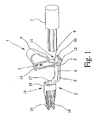
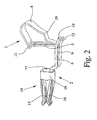
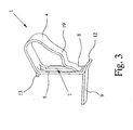
- the Fig. 1 and 2 show a clamping spring 1 and a metal part 2 of an electrical connection or connection terminal.
- the clamping spring 1 has a clamping leg 4 and a contact leg 5, wherein the clamping leg 4 and the contact leg 5 are approximately perpendicular to each other.
- the metal part 2 has a busbar piece 6 and an integral with the busbar piece 6 female part 14.
- a recess 7 is formed in the contact leg 5 of the clamping spring 1, in which the tip of the electrical conductor 3 to be connected can be inserted.
- the end 8 of the clamping leg 4 extends into the recess 7 in the plant leg 5 inside.
- the clamping spring 1 thus has an approximately loop-shaped contour, wherein the bearing leg 5 and thus also the recess 7 is substantially perpendicular to the insertion direction of the electrical conductor to be connected 3 and perpendicular to the busbar piece 6.
- the clamping spring 1 has a holding section 9, which is punched out of the plant leg 5.
- the bearing limb 5 and the holding portion 9 are substantially perpendicular to each other, while the busbar piece 6 and the holding portion 9 are substantially parallel to each other.
- a fixation of the clamping spring 1 to the metal part 2 and the metal part 2 on the clamping spring 1 is now easy to manufacture, that the busbar piece 6 is inserted opposite to the insertion of the electrical conductor 3 to be connected through the recess 7, wherein the busbar piece 6 on the holding portion 9 rests and is pressed by the end 8 of the clamping leg 4 against the holding portion 9.
- the end 10 of the busbar piece 6 protrudes through the recess 7 in the plant leg 5 therethrough.
- the position of the clamping spring 1 can be further fixed in that in the insulating housing, a groove or shoulder for receiving or support of the mounting web 13 is formed, which is at the opposite end of the holding portion 9 of the recess 7 punched out of the plant leg 5 and bent
- the metal part 2 in addition to the busbar piece 6 still a socket part 14.
- the busbar piece 6 may also be connected to a pin-shaped connector part.
- an over-spring 18 is provided, which is adapted to the geometry of the female part 14.
- the metal part 2 in total, ie both the busbar piece 6 and the female part 14, are made of a highly electrically conductive material, in particular of a copper alloy, while the over-spring 18 is made of a material with a high spring rate, for example of spring steel.
- the clamping leg 4 of the clamping spring 1 has a kink 19 which is aligned in the direction of the spring force of the clamping leg 4, so that through the kink 19 an improved point of application for the tip of an actuating tool for opening the clamping spring 1 is realized.
Landscapes
- Connections Arranged To Contact A Plurality Of Conductors (AREA)
- Connections Effected By Soldering, Adhesion, Or Permanent Deformation (AREA)
- Conductive Materials (AREA)
- Connection Of Batteries Or Terminals (AREA)
Abstract
Description
Die Erfindung betrifft eine elektrische Anschluß- oder Verbindungsklemme mit einer Klemmfeder und mit einem Metallteil, wobei die Klemmfeder und das Metallteil in einem eine Leitereinführungsöffnung zum Einführen eines anzuschließenden elektrischen Leiters aufweisenden Isoliergehäuse angeordnet sind, die Klemmfeder einen Klemmschenkel und einen Anlageschenkel und das Metallteil zumindest ein Stromschienenstück aufweist und wobei der Klemmschenkel und das Stromschienenstück einen Federkraftklemmanschluß für den anzuschließenden elektrischen Leiter bilden.The invention relates to an electrical connection or connection terminal with a clamping spring and a metal part, wherein the clamping spring and the metal part are arranged in a conductor insertion opening for insertion of an electrical conductor to be connected insulating housing, the clamping spring a clamping leg and a plant leg and the metal part at least one Bus bar piece and wherein the clamping leg and the busbar piece form a spring terminal connection for the electrical conductor to be connected.
Elektrische Anschluß- oder Verbindungseinrichtungen dienen dazu, einen elektrischen Anschluß oder eine elektrische Verbindung herzustellen, nämlich zwischen einem Kontaktelement und einem Gegenkontaktelement eine elektrisch leitende Verbindung herzustellen, und zwar eine galvanische Verbindung. Ob im Einzelfall eine Anschlußeinrichtung oder eine Verbindungseinrichtung vorliegt, ist funktional relativ belanglos. Von einer Anschlußeinrichtung spricht man häufig dann, wenn etwas Ortsbewegliches an etwas Ortsfestes angeschlossen wird, während man von einer Verbindungseinrichtung häufig dann spricht, wenn etwas Ortsbewegliches mit etwas Ortsbeweglichem oder auch wenn etwas Ortsfestes mit etwas Ortsfestem verbunden wird.Electrical connection or connection devices serve to produce an electrical connection or an electrical connection, namely to produce an electrically conductive connection between a contact element and a mating contact element, namely a galvanic connection. Whether in a particular case a connection device or a connection device is present, is functionally relatively irrelevant. From a connection device is often spoken when something portable is connected to something stationary, while often speaks of a connecting device then, if something portable with something Ortsbeweglichem or even if something stationary is connected to something stationary.
Eine eingangs beschriebene elektrische Anschlußklemme ist beispielsweise aus der
Die Klemmfeder ist dabei dadurch mit dem Kontaktelement verbunden, daß das Ende des zweiten Schenkels der Klemmfeder oberhalb der Steeköfinung an dem Kontaktelement festgenietet ist. Bei der bekannten Anschlußklemme ist die Fixierung der Klemmfeder an dem Kontaktelement mittels Nieten relativ umständlich. Darüber hinaus ist die Baugröße der bekannten Anschluß-' klemme relativ groß, insbesondere ist die Anschlußklemme relativ hoch, da durch die Fixierung des zweiten Schenkels der Klemmfeder oberhalb der Steeköffnung auch der rückwärtige Federbogen der Klemmfeder im wesentlichen oberhalb des näherungsweise L-förmigen Kontaktelements angeordnet ist.The clamping spring is thereby connected to the contact element, that the end of the second leg of the clamping spring is riveted above the Steeköfinung on the contact element. In the known terminal, the fixation of the clamping spring on the contact element by means of rivets is relatively cumbersome. In addition, the size of the known terminal 'terminal is relatively large, in particular, the terminal is relatively high, since the fixing of the second leg of the clamping spring above the Steeköffnung and the rear spring bow of the clamping spring is disposed substantially above the approximately L-shaped contact element ,
Aus der
Der vorliegenden Erfindung liegt daher die Aufgabe zugrunde, eine eingangs beschriebene elektrische Anschluß- oder Verbindungsklemme zur Verfügung zu stellen, welche bei einer möglichst geringen Baugröße eine einfache aber dennoch sichere Fixierung der Klemmfeder ermöglicht.The present invention is therefore an object of the invention to provide an electrical connection or connection terminal described above, which allows for the smallest possible size a simple yet secure fixation of the clamping spring.
Diese Aufgabe ist bei der eingangs beschriebenen elektrischen Anschluß- oder Verbindungsklemme dadurch gelöst, daß in dem Anlageschenkel der Klemmfeder eine Ausnehmung zum Einstecken des Leiters ausgebildet ist, daß der Klemmschenkel und der Anlageschenkel der Klemmfeder derart aufeinander zugebogen sind, daß sich das Ende des Klemmschenkels durch die Ausnehmung in dem Anlageschenkel hindurcherstreckt, und daß die Klemmfeder einen Halteabschnitt aufweist, der im wesentlichen parallel zur Einsteckrichtung des anzuschließenden elektrischen Leiters und parallel zum Stromschienenstück verläuft, derart, daß das Stromschienenstück entgegengesetzt zur Einsteckrichtung des anzuschließenden Leiters durch die Ausnehmung einsteckbar ist, wobei das Stromschienenstück zwischen dem Ende des Klemmschenkels und dem Halteabschnitt festgeklemmt ist.This object is achieved in the electrical connection or connection terminal described above, characterized in that in the plant leg of the clamping spring is formed a recess for insertion of the conductor, that the clamping leg and the plant leg of the clamping spring are zugebogen such that the end of the clamping leg through extends through the recess in the plant leg, and that the clamping spring has a holding portion which is parallel to the insertion direction of the electrical conductor to be connected and parallel to the busbar piece, such that the busbar piece opposite to the insertion direction of the conductor to be connected through the recess can be inserted, wherein the Busbar piece between the end of the clamping leg and the holding portion is clamped.
Die erfindungsgemäße elektrische Anschluß- oder Verbindungsklemme unterscheidet sich somit zunächst dadurch von den aus dem Stand der Technik bekannten Anschlußklemmen, daß die Klemmfeder nicht U-förmig sondern eher schlaufenförmig ausgebildet ist. Darüber hinaus ist bei der erfindungsgemäßen elektrischen Anschluß- oder Verbindungsklemme die Ausnehmung zum Einstecken des anzuschließenden elektrischen Leiters nicht in einem Teilstück der Stromschiene sondern in dem Anlageschenkel der Klemmfeder ausgebildet. Bei der erfindungsgemäßen Anschluß- oder Verbindungsklemme erfolgt die Fixierung von Klemmfeder und Stromschiene somit nicht dadurch, daß die Klemmfeder mit den Enden ihrer Schenkel in eine Öffnung in der Stromschiene sondern die Stromschiene in die Ausnehmung im Anlageschenkel der Klemmfeder eingesteckt wird.The electrical connection or connection terminal according to the invention thus initially differs from the known from the prior art terminals, that the clamping spring is not U-shaped but rather loop-shaped. Moreover, in the electrical connection or connection terminal according to the invention, the recess for insertion of the electrical conductor to be connected is not formed in a section of the busbar but in the contact leg of the clamping spring. In the connection or connection terminal according to the invention, the fixation of clamping spring and busbar is thus not characterized in that the clamping spring is inserted with the ends of their legs in an opening in the busbar but the busbar in the recess in the plant leg of the clamping spring.
Zur Befestigung der Klemmfeder relativ zum Metallteil ist an der Klemmfeder ein Halteabschnitt ausgebildet, so daß das Stromschienenstück zwischen dem Ende des Klemmschenkels und dem Halteabschnitt festgeklemmt wird. Wie im Stand der Technik auch, bilden das Ende des Klemmschenkels und das Stromschienenstück die Klemmstelle für den elektrischen Leiter, in dem das Ende des Klemmschenkels den anzuschließenden elektrischen Leiter gegen das Stromschienenstück drückt.For fixing the clamping spring relative to the metal part, a holding portion is formed on the clamping spring, so that the busbar piece between the end of the clamping leg and the holding portion is clamped. As in the prior art, the end of the clamping leg and the busbar piece form the terminal point for the electrical conductor, in which the end of the clamping leg presses the electrical conductor to be connected against the busbar piece.
Schlaufenförmige Klemmfedern bei elektrischen Anschluß- oder Verbindungsklemmen sind grundsätzlich aus dem Stand der Technik bekannt, nämlich als sogenannt Zugfedern in Zugfederklemmen(vgl.
Die bekannten Zugfederklemmen unterscheiden sich jedoch sowohl in der Ausgestaltung als auch in ihrer Funktion deutlich von der erfindungsgemäßen Anschluß- oder Verbindungsklemme. Bei den bekannten schlaufenförrnigen Zugfedern wird - entsprechend ihrem Namen- der anzuschließende Leiter vom Klemmschenkel gegen die Stromschiene gezogen. Im Unterschied dazu wird bei der erfindungsgemäßen Anschluß- oder Verbindungsklemme der anzuschließende Leiter vom Klemmschenkel gegen das Stromschienenstück gedrückt. Darüber hinaus ist bei Zugfedern im Klemmschenkel eine Ausnehmung vorgesehen, während bei der Klemmfeder der erfindungsgemäßen Anschluß- oder Verbindungsklemme die Ausnehmung im Anlageschenkel ausgebildet ist.However, the known tension spring terminals differ significantly both in design and in their function of the connection or connection terminal according to the invention. In the known schlaufförrnigen tension springs - according to their name - the conductor to be connected pulled by the clamping leg against the busbar. In contrast, in the connection or connection terminal according to the invention the conductor to be connected is pressed by the clamping leg against the busbar piece. In addition, a recess is provided with tension springs in the clamping leg, while in the clamping spring of the connection or connection terminal according to the invention, the recess is formed in the plant leg.
Gemäß einer vorteilhaften Ausgestaltung der Erfindung ist der Halteabschnitt der Klemmfeder aus dem Anlageschenkel freigestanzt und abgebogen. Der Halteabschnitt entspricht dabei dem Material des Anlageschenkels, das bei der Ausbildung der Ausnehmung aus dem Anlageschenkel freigestanzt wird. Somit können die Ausnehmung und der Halteabschnitt besonders einfach und materialsparend durch einen Stanz- und Biegevorgang hergestellt werden. Durch die Einstückigkeit des Anlageschenkels und des Halteabschnitts ist darüber hinaus ein weiterer Verfahrensschritt zur Verbindung des Halteabschnitts mit der Klemmfeder nicht erforderlich. Gemäß einer weiteren vorteilhaften Ausgestaltung der Erfindung ist das Ende des Stromschienenstücks derart abgebogen, daß das Ende des Stromschienenstücks zusammen mit dem Ende des Klemmschenkels der Klemmfeder einen Einführtrichter für den anzuschließenden elektrischen Leiter bilden. Durch die Ausbildung des Einführtrichters wird somit die Spitze eines durch die Leitereinführungsöffnung in das Isoliergehäuse eingeschobenen elektrischen Leiters automatisch richtig positioniert, so daß ein einfaches und exaktes Anschließen eines elektrischen Leiters an die elektrische Anschluß- oder Verbindungsklemme möglich ist.According to an advantageous embodiment of the invention, the holding portion of the clamping spring is punched out of the plant leg and bent. The holding portion corresponds to the material of the abutment leg, which is punched out of the plant leg in the formation of the recess. Thus, the recess and the holding portion can be made particularly simple and material-saving by a punching and bending process. Due to the integral nature of the abutment leg and of the holding section, a further method step for connecting the holding section to the clamping spring is not required beyond that. According to a further advantageous embodiment of the invention, the end of the busbar piece is bent so that the end of the busbar piece together with the end of the clamping leg of the clamping spring form an insertion funnel for the electrical conductor to be connected. Due to the design of the insertion funnel thus the tip of an inserted through the conductor insertion opening in the insulating electrical conductor is automatically positioned correctly, so that a simple and accurate connection of an electrical conductor to the electrical connection or connection terminal is possible.
Wie zuvor bereits ausgeführt, ist die erfindungsgemäße elektrische Anschluß- oder Verbindungseinrichtung vorzugsweise als Steckverbinder ausgebildet, so daß das Metallteil außer dem Stromschienenstück noch ein Stecker- oder Buchsenteil aufweist, wobei das Stromschienenstück und der Stecker- oder Buchsenteil einstückig ausgebildet sind, so daß das Metallteil insgesamt einfach durch Stanzen und Biegen herstellbar ist.As already stated above, the electrical connection or connection device according to the invention is preferably designed as a connector so that the metal part except the busbar piece still has a male or female part, wherein the busbar piece and the male or female part are integrally formed, so that the metal part All in all easy to produce by punching and bending.
Gute elektrische Steckverbinder zeichnen sich dadurch aus, daß im kontaktierten Zustand der Übergangswiderstand zwischen dem Kontaktelement, d. h. dem Stecker- oder Buchsenteil, und dem korrespondierenden Gegenkontaktelement dauerhaft einen möglichst geringen Wert aufweist. Der Übergangswiderstand zwischen dem Kontaktelement und dem mit dem Kontaktelement kontaktierten Gegenkontaktelement hängt dabei von der Geometrie von Kontaktelement und Gegenkontaktelement, von den Materialien von Kontaktelement und Gegenkontaktelement und insbesondere von der Kontaktkraft bzw. dem Kontaktdruck zwischen dem Kontaktelement und dem Gegenkontaktelement ab. Die Kontaktkraft wird in der Regel dadurch erzielt, daß beim Kontaktieren das Kontaktelement elastisch verformt wird, so daß aus der elastischen Verformung eine Rückstellkraft als Kontaktkraft und daraus resultierend dann ein entsprechender Kontaktdruck entstehtGood electrical connectors are characterized in that in the contacted state of the contact resistance between the contact element, d. H. the male or female part, and the corresponding mating contact element permanently has the lowest possible value. The contact resistance between the contact element and the contacted with the contact element mating contact element depends on the geometry of contact element and mating contact element, of the materials of contact element and mating contact element and in particular from the contact force or the contact pressure between the contact element and the mating contact element. The contact force is usually achieved in that when contacting the contact element is elastically deformed, so that from the elastic deformation of a restoring force as a contact force and then resulting in a corresponding contact pressure
Problematisch ist nun, daß bei Verwendung eines gut leitenden Materials für das Kontaktelement, d. h. für den Stecker- oder Buchsenteil des Metallteils, die Federrate des Kontaktelements relativ gering ist, so daß keine ausreichende und dauerhafte Kontaktkraft realisiert werden kann. Gemäß einer vorteilhaften Ausgestaltung einer elektrischen Anschluß- oder Verbindungsklemme mit einem zwei einander gegenüberliegende Schenkel und einen die Schenkel verbindenden Steg aufweisenden Buchsenteil ist dieser Nachteil dadurch behoben, daß eine Überfeder vorgesehen ist, die das Buchsenteil umgibt. Die Überfeder, die im wesentlichen der Geometrie des Buchsenteils angepaßt ist, kann dabei beispielsweise aus Federstahl hergestellt sein. Im Unterschied dazu ist das Metallteil und damit auch das Buchsenteil selber aus einem Material mit einer guten Leitfähigkeit hergestellt, beispielsweise aus einer Kupferlegierung.The problem now is that when using a highly conductive material for the contact element, ie for the male or female part of the metal part, the spring rate of the contact element is relatively low, so that no sufficient and lasting contact force can be realized. According to an advantageous embodiment of an electrical connection or connection terminal with a two opposing legs and a connecting leg connecting leg, this disadvantage is eliminated in that an over-spring is provided, which surrounds the socket part. The over-spring, which is adapted substantially to the geometry of the socket part, can be made for example of spring steel. In contrast, the metal part and thus also the socket part itself is made of a material with a good conductivity, for example of a copper alloy.
Gemäß einer letzten vorteilhaften Ausgestaltung der Erfindung, die hier noch kurz erwähnt werden soll, weist das Isoliergehäuse eine Betätigungsöffnung zum Einführen eines Betätigungswerkzeugs auf und ist an dem Klemmschenkel der Klemmfeder ein Knick ausgebildet, der in Richtung der Federkraft des Klemmschenkels ausgerichtet ist, so daß die Spitze des Betätigungswerkzeugs zum Öffnen der Klemmfeder an dem Knick angreifen kann. Durch das Vorsehen einer Betätigungsöffnung zum Einführen eines Betätigungswerkzeugs wird zunächst erreicht, daß das elektrische Anschluß- oder Verbindungsklemme auch für feindrähtige flexible Leiter verwendet werden kann, bei denen ein Öffnen der Klemmfeder lediglich durch Einstecken des elektrischen Leiters nicht möglich ist. Darüber hinaus kann durch das Öffnen der Klemmfeder mit Hilfe des Betätigungswerkzeugs auch ein bereits geklemmter elektrischer Leiter wieder aus der Klemmstelle gelöst werden. Der an dem Klemmschenkel ausgebildete Knick ermöglicht dabei ein einfacheres Angreifen der Spitze des Betätigungswerkzeugs am Klemmschenkel zum Öffnen der Klemmfeder.According to a last advantageous embodiment of the invention, which will be briefly mentioned here, the insulating housing has an actuating opening for insertion of an actuating tool and is formed on the clamping leg of the clamping spring a kink, which is aligned in the direction of the spring force of the clamping leg, so that the Tip of the actuating tool for opening the clamping spring can act on the kink. By providing an actuating opening for insertion of an actuating tool is first achieved that the electrical connection or connection terminal can also be used for fine-wire flexible conductor, in which an opening of the clamping spring is not possible only by inserting the electrical conductor. In addition, by opening the clamping spring by means of the actuating tool, an already clamped electrical conductor can be released from the nip again. The formed on the clamping leg kink allows easier engagement of the tip of the actuating tool on the clamping leg to open the clamping spring.
Im einzelnen gibt es nun eine Vielzahl von Möglichkeiten, die erfindungsgemäße elektrische Anschluß- oder Verbindungsklemme auszugestalten und weiterzubilden. Dazu wird verwiesen einerseits auf die dem Patentanspruch 1 nachgeordneten Patentansprüche, andererseits auf die nachfolgende Beschreibung eines bevorzugten Ausführungsbeispiels in Verbindung mit der Zeichnung. In der Zeichnung zeigen
- Fig. 1
- eine erfindungsgemäße elektrische Anschluß- oder Verbindungsklemme mit einem anzuschließenden elektrischen Leiter,
- Fig. 2
- eine weitere Ansicht der erfindungsgemäßen elektrischen Anschluß- oder Verbindungseinrichtung und
- Fig. 3
- die Klemmfeder der elektrischen Anschluß- oder Verbindungsklemme gemäß den
Fig. 1 und2 .
- Fig. 1
- an electrical connection or connection terminal according to the invention with an electrical conductor to be connected,
- Fig. 2
- a further view of the electrical connection or connection device according to the invention and
- Fig. 3
- the clamping spring of the electrical connection or connection terminal according to
Fig. 1 and2 ,
Die
Wie insbesondere aus den
Neben dem Klemmschenkel 4 und dem Anlageschenkel 5 weist die Klemmfeder 1 noch einen Halteabschnitt 9 auf, der aus dem Anlageschenkel 5 freigestanzt ist. Wie sich aus den Figuren ergibt, verlaufen der Anlageschenkel 5 und der Halteabschnitt 9 im wesentlichen senkrecht zueinander, während das Stromschienenstück 6 und der Halteabschnitt 9 im wesentlichen parallel zueinander verlaufen.In addition to the clamping
Aus der
Eine Fixierung der Klemmfeder 1 an dem Metallteil 2 bzw. des Metallteils 2 an der Klemmfeder 1 ist nun dadurch einfach herstellbar, daß das Stromschienenstück 6 entgegengesetzt zur Einsteckrichtung des anzuschließenden elektrischen Leiters 3 durch die Ausnehmung 7 eingesteckt wird, wobei das Stromschienenstück 6 auf dem Halteabschnitt 9 aufliegt und durch das Ende 8 des Klemmschenkels 4 gegen den Halteabschnitt 9 gedrückt wird. Dabei ragt das Ende 10 des Stromschienenstücks 6 durch die Ausnehmung 7 im Anlageschenkel 5 hindurch. Hierdurch wird sowohl eine gute Auflage des Stromschienenstücks 6 auf dem Halteabschnitt 9 als auch eine ausreichende Klemmung des Stromschienenstücks 6 zwischen dem Anlageschenkel 5 und dem Halteabschnitt 9 gewährleistet. Die Position der Klemmfeder 1 kann dadurch weiter fixiert werden, daß in dem Isoliergehäuse eine Nut oder eine Schulter zur Aufnahme bzw. Auflage des Befestigungssteges 13 ausgebildet ist, der an dem dem Halteabschnitt 9 gegenüberliegenden Ende der Ausnehmung 7 aus dem Anlageschenkel 5 freigestanzt und abgebogen istA fixation of the
Bei dem in den
Der Klemmschenkel 4 der Klemmfeder 1 weist einen Knick 19 auf, der in Richtung der Federkraft des Klemmschenkels 4 ausgerichtet ist, so daß durch den Knick 19 ein verbesserter Angriffspunkt für die Spitze eines Betätigungswerkzeugs zum Öffnen der Klemmfeder 1 realisiert ist. Insgesamt ist aus den Figuren ersichtlich, daß bei der erfindungsgemäßen elektrischen Anschluß- oder Verbindungsklemme die Fixierung von Klemmfeder 1 und Metallteil 2 besonders einfach herstellbar ist, wobei gleichzeitig eine kleine und kompakte Bauform der elektrischen Anschluß- oder Verbindungsklemme erreichbar ist.The clamping
Claims (9)
- Electrical connection or connecting terminal with a clamping spring (1) and with a metal part (2), the clamping spring (1) and the metal part (2) being arranged in an insulating housing, which has a conductor insertion opening for inserting an electrical conductor (3) to be connected, the clamping spring (1) having a clamping limb (4) and a bearing limb (5), and the metal part (2) having at least one busbar piece (6), and the clamping limb (4) and the busbar piece (6) forming a spring-force clamping connection for the electrical conductor (3) to be connected,
characterized in that
a cutout (7) for plugging in an electrical conductor (3) to be connected is formed in the bearing limb (5) of the clamping spring (1), in that the clamping limb (4) and the bearing limb (5) of the clamping spring (1) are bent towards one another in such a way that the end (8) of the clamping limb (4) extends through the cutout (7), and in that the clamping spring (1) has a holding section (9), which runs substantially parallel to the plug-in direction of the electrical conductor (3) to be connected and parallel to the busbar piece (6) in such a way that the busbar piece (6) can be plugged in through the cutout (7) in the opposite direction to the plug-in direction of the electrical conductor (3) to be connected, the busbar piece (6) being fixedly clamped between the end (8) of the clamping limb (4) and the holding section (9). - Electrical connection or connecting terminal according to Claim 1, characterized in that the holding section (9) of the clamping spring (1) is stamped free from the bearing limb (5) and is bent back.
- Electrical connection or connecting terminal according to Claim 1 or 2, characterized in that the end (10) of the busbar piece (6) is bent back, with the result that the end (10) of the busbar piece (6) together with the end (8) of the clamping limb (4) form an insertion funnel (11) for the electrical conductor (3) to be connected.
- Electrical connection or connecting terminal according to one of Claims 1 to 3, characterized in that the bearing limb (5) runs substantially perpendicularly with respect to the plug-in direction of the electrical conductor (3) to be connected, the busbar piece (6) rests on the holding section (9), and the end (10) of the busbar piece (6) protrudes through the cutout (7) and rests on the end (12) of the bearing limb (5).
- Electrical connection or connecting terminal according to one of Claims 2 to 4, characterized in that a fixing web (13) is stamped free from the bearing limb (5) and is bent back at that end of the cutout (7) which is opposite the holding section (9).
- Electrical connection or connecting terminal according to one of Claims 1 to 5, characterized in that the busbar piece (6) is connected to a plug or socket part (14).
- Electrical connection or connecting terminal according to Claim 5, with a socket part (14), which has two mutually opposite limbs (15, 16) and a web (17) connecting the limbs (15, 16), characterized in that the socket part (14) is surrounded by a surrounding spring (18), the surrounding spring (18) being matched substantially to the geometry of the socket part (14).
- Electrical connection or connecting terminal according to one of Claims 1 to 7, characterized in that the insulating housing has an actuating opening for inserting an actuating tool, and in that a kink (19) is formed on the clamping limb (4), which kink (19) is oriented in the direction of the spring force of the clamping limb (4), so that the tip of an actuating tool can act on the kink (19) so as to open the clamping spring (1).
- Electrical connection or connecting terminal according to one of Claims 1 to 8, characterized in that the metal part (2) is produced from a copper alloy.
Applications Claiming Priority (1)
| Application Number | Priority Date | Filing Date | Title |
|---|---|---|---|
| DE102004045025A DE102004045025B3 (en) | 2004-09-15 | 2004-09-15 | Electrical connection or connection terminal |
Publications (3)
| Publication Number | Publication Date |
|---|---|
| EP1638169A2 EP1638169A2 (en) | 2006-03-22 |
| EP1638169A3 EP1638169A3 (en) | 2007-02-21 |
| EP1638169B1 true EP1638169B1 (en) | 2008-06-11 |
Family
ID=35427938
Family Applications (1)
| Application Number | Title | Priority Date | Filing Date |
|---|---|---|---|
| EP05018678A Not-in-force EP1638169B1 (en) | 2004-09-15 | 2005-08-29 | Electric connecting terminal |
Country Status (7)
| Country | Link |
|---|---|
| US (1) | US7083463B2 (en) |
| EP (1) | EP1638169B1 (en) |
| JP (1) | JP4728074B2 (en) |
| CN (1) | CN100499268C (en) |
| AT (1) | ATE398348T1 (en) |
| DE (2) | DE102004045025B3 (en) |
| DK (1) | DK1638169T3 (en) |
Families Citing this family (75)
| Publication number | Priority date | Publication date | Assignee | Title |
|---|---|---|---|---|
| US7527509B1 (en) * | 2005-06-21 | 2009-05-05 | Ideal Industries, Inc. | Electrical disconnect with push-in connectors |
| US20060286839A1 (en) * | 2005-06-21 | 2006-12-21 | Bethurum Gary C | Electrical Disconnect With Push-In Connectors |
| DE102005045596B3 (en) * | 2005-09-23 | 2007-06-21 | Siemens Ag | Spring plug terminal |
| ITMI20060373A1 (en) * | 2006-03-02 | 2007-09-03 | Ilme Spa | ELECTRIC MULTIPOLAR CONNECTOR WITH SPRING CONTACTS |
| DE202006003400U1 (en) * | 2006-03-04 | 2007-07-12 | Weidmüller Interface GmbH & Co. KG | Connection system with direct plug connection |
| DE102006014646B4 (en) * | 2006-03-28 | 2008-06-26 | Phoenix Contact Gmbh & Co. Kg | Terminal for printed circuit boards |
| CA2573845C (en) * | 2006-04-20 | 2009-11-24 | Thomas & Betts International, Inc. | Electrical connector components |
| US7727002B2 (en) * | 2006-06-21 | 2010-06-01 | Ideal Industries, Inc. | Electrical disconnect with adjacent wire receptacle boxes |
| US7175469B1 (en) * | 2006-07-21 | 2007-02-13 | Tyco Electronics Corporation | Connector having dual tabbed wire trap |
| ITTO20060757A1 (en) * | 2006-10-20 | 2008-04-21 | Itw Ind Components Srl | RAPID RELEASE CONTACT SUITABLE FOR EQUIPMENT A TERMINAL BOARD, IN PARTICULAR FOR A LIGHTER ELECTRONIC DEVICE FOR HOUSEHOLD APPLIANCES |
| DE202006016238U1 (en) * | 2006-10-24 | 2007-12-13 | FILTEC GmbH Filtertechnologie für die Elektronikindustrie | Contact insert for connectors that can be connected to signal or power supply lines |
| KR100854064B1 (en) * | 2006-12-05 | 2008-08-25 | 한국전자통신연구원 | Method for reduction of peak to average power ratio at orthogonal frequency division multiplexing system |
| CN201051541Y (en) * | 2007-05-08 | 2008-04-23 | 康联精密机电(深圳)有限公司 | A wiring device |
| DE102007022806B3 (en) * | 2007-05-11 | 2008-11-27 | Wago Verwaltungsgesellschaft Mbh | clamping member |
| DE102007024690B4 (en) * | 2007-05-25 | 2009-06-04 | Phoenix Contact Gmbh & Co. Kg | Electrical connection or connection terminal |
| DE102007036295B4 (en) * | 2007-07-31 | 2009-10-08 | Phoenix Contact Gmbh & Co. Kg | Plug-in PCB terminal block |
| DE102008024366B4 (en) * | 2008-05-20 | 2010-11-25 | Phoenix Contact Gmbh & Co. Kg | Through terminal |
| US7618279B1 (en) | 2008-06-26 | 2009-11-17 | Thomas & Betts International, Inc. | One-piece push-in electrical contact terminal |
| FR2936657B1 (en) * | 2008-09-29 | 2010-10-22 | Legrand France | ELECTRICAL CONNECTION TERMINAL COMPRISING AN ALVEOLE AND A CONNECTION LEG BELOWING THE SAME PIECE |
| DE102008061268B4 (en) * | 2008-12-10 | 2017-02-23 | Phoenix Contact Gmbh & Co. Kg | Contact terminal and connector with contact terminal |
| US7785134B2 (en) * | 2008-12-30 | 2010-08-31 | General Electric Company | Contact terminal for conductors |
| DE102009004513A1 (en) * | 2009-01-09 | 2010-07-22 | Phoenix Contact Gmbh & Co. Kg | Clamping spring for a spring-loaded terminal |
| FR2946187B1 (en) * | 2009-05-26 | 2011-06-03 | Finsecur | LAMINATED CONNECTOR, TOOL FOR ACTING THIS CONNECTOR, KIT AND FIRE DETECTOR HAVING THE SAME |
| DE202010008028U1 (en) * | 2009-07-18 | 2010-12-30 | Weidmüller Interface GmbH & Co. KG | Connection device for conductors |
| WO2011140438A2 (en) * | 2010-05-07 | 2011-11-10 | Amphenol Corporation | High performance cable connector |
| DE102010024809B4 (en) * | 2010-06-23 | 2013-07-18 | Wago Verwaltungsgesellschaft Mbh | terminal |
| ES2473892T3 (en) * | 2010-10-12 | 2014-07-08 | Bals Elektrotechnik Gmbh & Co. Kg | Screwless connection terminal |
| US8353716B2 (en) * | 2010-12-14 | 2013-01-15 | Ideal Industries, Inc. | Terminal structures for wiring devices |
| US8951064B2 (en) | 2010-12-14 | 2015-02-10 | Ideal Industries, Inc. | Terminal structures for wiring devices |
| DE102010063978A1 (en) * | 2010-12-22 | 2012-06-28 | Beckhoff Automation Gmbh | Connection module and connection system |
| DE102011011080B4 (en) * | 2011-02-11 | 2013-04-11 | Wago Verwaltungsgesellschaft Mbh | Spring clamp connection and conductor connection unit |
| CN102694282A (en) * | 2011-03-23 | 2012-09-26 | 宁波速普电子有限公司 | Plug-in connection device |
| CN102842785A (en) * | 2011-06-20 | 2012-12-26 | 町洋企业股份有限公司 | Improved structure of wiring terminal |
| DE102011054425A1 (en) * | 2011-10-12 | 2013-04-18 | Phoenix Contact Gmbh & Co. Kg | Spring element for spring force clamping assembly, has clamping arm which is formed in U-shape and provided with free end portion that is projected into through opening of support leg |
| US9130285B2 (en) | 2012-09-05 | 2015-09-08 | Hubbell Incorporated | Push wire connector having a spring biasing member |
| CN102938511A (en) * | 2012-11-15 | 2013-02-20 | 宁波速普电子有限公司 | Conductor clamping mechanism and connecting terminal |
| JP6088279B2 (en) * | 2013-02-12 | 2017-03-01 | 日本圧着端子製造株式会社 | Pressure contact type contact |
| DE102013101411B4 (en) * | 2013-02-13 | 2018-03-22 | Wago Verwaltungsgesellschaft Mbh | Spring terminal connection and conductor terminal |
| CN104143712B (en) * | 2013-05-10 | 2016-09-07 | 町洋机电(中国)有限公司 | Spring economizing type electric connector |
| WO2015036472A1 (en) * | 2013-09-16 | 2015-03-19 | Weidmüller Interface GmbH & Co. KG | Clamping cage for an edge connector |
| FR3010840A1 (en) * | 2013-09-17 | 2015-03-20 | Schneider Electric Ind Sas | ELECTRICAL CONNECTION TERMINAL OF AN ELECTRIC APPARATUS SUPPLIED BY A COMB AND APPARATUS COMPRISING SUCH A TERMINAL |
| US20150249295A1 (en) * | 2014-03-03 | 2015-09-03 | Heavy Power Co. Ltd. | Disconnect with enhanced electrical contact |
| FR3020507B1 (en) * | 2014-04-29 | 2017-12-01 | Abb France | REMOVABLE CONNECTOR |
| US9553387B2 (en) * | 2014-07-15 | 2017-01-24 | Industria Lombarda Materiale Elettrico—I.L.M.E. S.P.A. | Electrical connecting device with spring connection element and compact actuator and multi-pole plug connector comprising a plurality of said spring contacts |
| DE102014114026B4 (en) * | 2014-09-26 | 2023-03-30 | Wago Verwaltungsgesellschaft Mbh | Conductor terminal and method of assembly |
| US9624951B2 (en) * | 2015-04-30 | 2017-04-18 | Dinkle Enterprise Co., Ltd. | Connection terminal structure |
| JP6563272B2 (en) * | 2015-08-04 | 2019-08-21 | タイコエレクトロニクスジャパン合同会社 | Electrical terminal |
| DE102015115612A1 (en) * | 2015-09-16 | 2017-03-16 | Phoenix Contact Gmbh & Co. Kg | Terminal for connecting an electrical conductor |
| CN105576420A (en) * | 2016-01-20 | 2016-05-11 | 莆田市多容光学电子有限公司 | Electric wire connector |
| US9806437B2 (en) | 2016-03-02 | 2017-10-31 | Hubbell Incorporated | Push wire connectors |
| US9941605B2 (en) | 2016-03-02 | 2018-04-10 | Hubbell Incorporated | Wire connectors with binding terminals |
| DE102016111627A1 (en) * | 2016-06-24 | 2017-12-28 | Wago Verwaltungsgesellschaft Mbh | Conductor terminal |
| JP6733368B2 (en) * | 2016-06-29 | 2020-07-29 | オムロン株式会社 | Terminal connection mechanism and switch |
| JP6666211B2 (en) * | 2016-07-19 | 2020-03-13 | タイコエレクトロニクスジャパン合同会社 | contact |
| CN106099417B (en) * | 2016-08-02 | 2019-02-22 | 马晓明 | Conductor wire binding clip |
| LU93183B1 (en) * | 2016-08-25 | 2018-03-28 | Phoenix Contact Gmbh & Co Kg Intellectual Property Licenses & Standards | terminal |
| CN109891675A (en) | 2016-09-29 | 2019-06-14 | 泰科电子服务有限责任公司 | There are two the electric connection systems of connection branch for tool |
| WO2018059696A1 (en) | 2016-09-29 | 2018-04-05 | Abb Schweiz Ag | Electrical connection system comprising an additional leaf spring |
| US10833435B2 (en) | 2016-09-29 | 2020-11-10 | TE Connectivity Services Gmbh | Electrical connection system with a conductive blade |
| US9705212B1 (en) * | 2016-10-05 | 2017-07-11 | Dinkle Enterprise Co., Ltd. | Structure improvement for connection terminals of terminal block |
| DE202017100038U1 (en) | 2017-01-06 | 2018-04-10 | Wago Verwaltungsgesellschaft Mbh | Conductor terminal |
| CN107255769A (en) * | 2017-05-02 | 2017-10-17 | 中国农业大学 | A kind of portable power distribution net fault locator |
| BE1025389B1 (en) * | 2017-07-14 | 2019-02-12 | Phoenix Contact Gmbh & Co. Kg | CONNECTION DEVICE FOR CONNECTING AN ELECTRICAL LINE |
| JP6931223B2 (en) * | 2017-07-25 | 2021-09-01 | 日本圧着端子製造株式会社 | Terminals and electrical connectors |
| DE102018109960A1 (en) * | 2018-04-25 | 2019-10-31 | Wieland Electric Gmbh | Connection box for electrical equipment |
| DE102018109959A1 (en) * | 2018-04-25 | 2019-10-31 | Wieland Electric Gmbh | Motor connection for an electric motor |
| WO2020010095A1 (en) | 2018-07-06 | 2020-01-09 | Hubbell Incorporated | Electrical plug connector and wiring device with keying features |
| DE102018117508B4 (en) * | 2018-07-19 | 2024-01-18 | Wago Verwaltungsgesellschaft Mbh | Conductor connection terminal |
| US10559897B1 (en) | 2018-09-07 | 2020-02-11 | Lear Corporation | Push-in electrical terminal with insulation contact |
| DE202018004944U1 (en) * | 2018-10-25 | 2020-01-28 | Electro Terminal Gmbh & Co Kg | Series plug-in terminal |
| DE102018127284A1 (en) * | 2018-10-31 | 2020-04-30 | Bals Elektrotechnik Gmbh & Co. Kg | Clamp spring for a screwless terminal |
| DE102018130533B3 (en) * | 2018-11-30 | 2020-02-13 | Wago Verwaltungsgesellschaft Mbh | connecting element |
| DE102020121004A1 (en) * | 2019-08-15 | 2021-02-18 | Phoenix Contact Gmbh & Co. Kg | Contact element and connection element |
| DE102019131141A1 (en) * | 2019-11-19 | 2021-05-20 | Phoenix Contact Gmbh & Co. Kg | Terminal arrangement, connector terminal and electronic device |
| US11749927B1 (en) * | 2022-03-03 | 2023-09-05 | Richard Goren Enterprises, Llc | Quick install banana plug |
Family Cites Families (23)
| Publication number | Priority date | Publication date | Assignee | Title |
|---|---|---|---|---|
| JPH0240387B2 (en) * | 1983-09-26 | 1990-09-11 | Hatsukoo Kk | KISETSUKANNOKANNAIMENHOSHURAININGUYOPIGUNOKOZO |
| DE3514099C2 (en) * | 1985-04-16 | 1994-11-17 | Wago Verwaltungs Gmbh | Connection clamp for electrical conductors |
| JPH0222572A (en) * | 1988-07-11 | 1990-01-25 | Yamaha Corp | Wiring inspecting method for integrated circuit |
| DE19646103C1 (en) * | 1996-11-08 | 1998-03-12 | Phoenix Contact Gmbh & Co | Bent metal cage spring clamp for mounting on current rail |
| DE19711051C5 (en) * | 1997-03-03 | 2015-03-19 | Wago Verwaltungsgesellschaft Mbh | Electrical terminal |
| DE19802945C2 (en) * | 1998-01-21 | 2001-04-26 | Wago Verwaltungs Gmbh | Electrical clamp |
| DE19817927C1 (en) * | 1998-04-17 | 1999-10-28 | Wago Verwaltungs Gmbh | Plug connector as socket or pin part with spring-loaded clamping connection for electric conductor |
| US6074242A (en) * | 1998-12-31 | 2000-06-13 | Methode Electronics, Inc. | Wire-trap connector for solderless compression connection |
| DE29915512U1 (en) * | 1999-09-03 | 2001-01-18 | Weidmüller Interface GmbH & Co., 32760 Detmold | Spring clip for connecting electrical conductors |
| DE29919903U1 (en) * | 1999-11-12 | 2001-03-29 | Weidmüller Interface GmbH & Co, 32760 Detmold | Tension spring connection for large conductor cross-sections |
| DE29920231U1 (en) * | 1999-11-17 | 2001-04-05 | Weidmüller Interface GmbH & Co, 32760 Detmold | Screwless terminal |
| DE10021027B4 (en) * | 2000-05-02 | 2009-12-17 | Wago Verwaltungsgesellschaft Mbh | Electrical terminal |
| DE10034589C2 (en) * | 2000-07-14 | 2002-12-12 | Phoenix Contact Gmbh & Co | Terminal for electrical conductors |
| DE10103145C1 (en) * | 2000-12-20 | 2002-06-27 | Hager Electro Gmbh | terminal block |
| JP4298955B2 (en) * | 2002-03-14 | 2009-07-22 | Idec株式会社 | Wiring connection device |
| DE20206763U1 (en) * | 2002-04-27 | 2002-09-19 | Wago Verwaltungsgesellschaft Mbh, 32423 Minden | terminal |
| DE20210105U1 (en) * | 2002-06-29 | 2002-10-02 | Wago Verwaltungsgmbh | Electrical connection for terminals, connectors or devices |
| US6719581B2 (en) * | 2002-07-25 | 2004-04-13 | Nippon Dics Co., Ltd. | Plug for speaker cables, and speaker terminal and speaker terminal system provided with them |
| DE10315668B4 (en) * | 2002-08-28 | 2007-06-06 | Conrad Stanztechnik Gmbh | terminal |
| FR2849290B1 (en) * | 2002-12-20 | 2007-01-05 | Hager Electro | ELECTRIC APPARATUS OF THE MODULAR TYPE WITH INCLINED CONNECTION FACES |
| DE20312861U1 (en) * | 2003-08-20 | 2003-10-30 | Phoenix Contact GmbH & Co. KG, 32825 Blomberg | Spring biased clamp for electric cables having a clamp tongue for the clamp spring |
| DE20313041U1 (en) * | 2003-08-23 | 2003-10-23 | Phoenix Contact GmbH & Co. KG, 32825 Blomberg | Clamping mechanism for conductor spring clamp with current carrying rail part with two flat straps on either side of clamping point, with flat straps contg. each bend towards conductor reception aperture |
| DE20313855U1 (en) * | 2003-09-06 | 2005-01-05 | Weidmüller Interface GmbH & Co. KG | Connecting device for direct plug connection of conductor ends |
-
2004
- 2004-09-15 DE DE102004045025A patent/DE102004045025B3/en not_active Expired - Fee Related
-
2005
- 2005-08-29 DK DK05018678T patent/DK1638169T3/en active
- 2005-08-29 DE DE502005004380T patent/DE502005004380D1/en active Active
- 2005-08-29 AT AT05018678T patent/ATE398348T1/en active
- 2005-08-29 EP EP05018678A patent/EP1638169B1/en not_active Not-in-force
- 2005-09-15 CN CNB200510113255XA patent/CN100499268C/en not_active Expired - Fee Related
- 2005-09-15 JP JP2005268947A patent/JP4728074B2/en not_active Expired - Fee Related
- 2005-09-15 US US11/226,441 patent/US7083463B2/en not_active Expired - Fee Related
Also Published As
| Publication number | Publication date |
|---|---|
| US7083463B2 (en) | 2006-08-01 |
| CN100499268C (en) | 2009-06-10 |
| JP2006086126A (en) | 2006-03-30 |
| EP1638169A3 (en) | 2007-02-21 |
| JP4728074B2 (en) | 2011-07-20 |
| EP1638169A2 (en) | 2006-03-22 |
| DE502005004380D1 (en) | 2008-07-24 |
| US20060063419A1 (en) | 2006-03-23 |
| ATE398348T1 (en) | 2008-07-15 |
| CN1750326A (en) | 2006-03-22 |
| DE102004045025B3 (en) | 2006-02-16 |
| DK1638169T3 (en) | 2008-10-13 |
Similar Documents
| Publication | Publication Date | Title |
|---|---|---|
| EP1638169B1 (en) | Electric connecting terminal | |
| DE102004046471B3 (en) | Electrical connection or connection terminal | |
| EP2162952B1 (en) | Electric connection clamp or terminal clamp | |
| EP2324533B1 (en) | Electrical connection terminal | |
| EP3320582B1 (en) | Connection terminal | |
| EP3446366B1 (en) | Plug contact | |
| EP1515397B1 (en) | Connector clamp for a direct plug in connection of electrical conductors | |
| EP3652808B1 (en) | Connection device for connection of an electrical line | |
| DE102004045026B3 (en) | Electrical connecting clamp for mobile and fixed functions, with clamping spring and metal part in insulating housing with inserting aperture for conductor to be inserted | |
| DE202010008028U1 (en) | Connection device for conductors | |
| EP2843764A1 (en) | Spring clamp for conductor | |
| EP2729992B1 (en) | Clamping unit of an electrical connection terminal | |
| WO2017032703A1 (en) | Electric terminal block | |
| EP3320583A1 (en) | Connection terminal | |
| DE102008008651B4 (en) | Electrical terminal | |
| DE102011009290B4 (en) | Terminal for printed circuit boards | |
| DE19817062C2 (en) | Clamping device for an electrical line | |
| DE202016102148U1 (en) | plug contact | |
| LU93147B1 (en) | terminal | |
| CH697113A5 (en) | Plug-in type electrical connecting device for connecting terminal clamps of electrical apparatuses, has connection pin introduced through push-to-open pins into electrical connection opening of clamping spring | |
| DE102017115865A1 (en) | Connecting device for connecting an electrical line |
Legal Events
| Date | Code | Title | Description |
|---|---|---|---|
| PUAI | Public reference made under article 153(3) epc to a published international application that has entered the european phase |
Free format text: ORIGINAL CODE: 0009012 |
|
| AK | Designated contracting states |
Kind code of ref document: A2 Designated state(s): AT BE BG CH CY CZ DE DK EE ES FI FR GB GR HU IE IS IT LI LT LU LV MC NL PL PT RO SE SI SK TR |
|
| AX | Request for extension of the european patent |
Extension state: AL BA HR MK YU |
|
| PUAL | Search report despatched |
Free format text: ORIGINAL CODE: 0009013 |
|
| AK | Designated contracting states |
Kind code of ref document: A3 Designated state(s): AT BE BG CH CY CZ DE DK EE ES FI FR GB GR HU IE IS IT LI LT LU LV MC NL PL PT RO SE SI SK TR |
|
| AX | Request for extension of the european patent |
Extension state: AL BA HR MK YU |
|
| 17P | Request for examination filed |
Effective date: 20070307 |
|
| 17Q | First examination report despatched |
Effective date: 20070514 |
|
| AKX | Designation fees paid |
Designated state(s): AT BE BG CH CY CZ DE DK EE ES FI FR GB GR HU IE IS IT LI LT LU LV MC NL PL PT RO SE SI SK TR |
|
| GRAP | Despatch of communication of intention to grant a patent |
Free format text: ORIGINAL CODE: EPIDOSNIGR1 |
|
| GRAS | Grant fee paid |
Free format text: ORIGINAL CODE: EPIDOSNIGR3 |
|
| GRAA | (expected) grant |
Free format text: ORIGINAL CODE: 0009210 |
|
| AK | Designated contracting states |
Kind code of ref document: B1 Designated state(s): AT BE BG CH CY CZ DE DK EE ES FI FR GB GR HU IE IS IT LI LT LU LV MC NL PL PT RO SE SI SK TR |
|
| REG | Reference to a national code |
Ref country code: GB Ref legal event code: FG4D Free format text: NOT ENGLISH |
|
| REG | Reference to a national code |
Ref country code: CH Ref legal event code: EP |
|
| REF | Corresponds to: |
Ref document number: 502005004380 Country of ref document: DE Date of ref document: 20080724 Kind code of ref document: P |
|
| REG | Reference to a national code |
Ref country code: IE Ref legal event code: FG4D Free format text: LANGUAGE OF EP DOCUMENT: GERMAN |
|
| REG | Reference to a national code |
Ref country code: SE Ref legal event code: TRGR |
|
| REG | Reference to a national code |
Ref country code: DK Ref legal event code: T3 |
|
| PG25 | Lapsed in a contracting state [announced via postgrant information from national office to epo] |
Ref country code: SI Free format text: LAPSE BECAUSE OF FAILURE TO SUBMIT A TRANSLATION OF THE DESCRIPTION OR TO PAY THE FEE WITHIN THE PRESCRIBED TIME-LIMIT Effective date: 20080611 Ref country code: FI Free format text: LAPSE BECAUSE OF FAILURE TO SUBMIT A TRANSLATION OF THE DESCRIPTION OR TO PAY THE FEE WITHIN THE PRESCRIBED TIME-LIMIT Effective date: 20080611 |
|
| PG25 | Lapsed in a contracting state [announced via postgrant information from national office to epo] |
Ref country code: LV Free format text: LAPSE BECAUSE OF FAILURE TO SUBMIT A TRANSLATION OF THE DESCRIPTION OR TO PAY THE FEE WITHIN THE PRESCRIBED TIME-LIMIT Effective date: 20080611 Ref country code: PL Free format text: LAPSE BECAUSE OF FAILURE TO SUBMIT A TRANSLATION OF THE DESCRIPTION OR TO PAY THE FEE WITHIN THE PRESCRIBED TIME-LIMIT Effective date: 20080611 |
|
| PG25 | Lapsed in a contracting state [announced via postgrant information from national office to epo] |
Ref country code: CZ Free format text: LAPSE BECAUSE OF FAILURE TO SUBMIT A TRANSLATION OF THE DESCRIPTION OR TO PAY THE FEE WITHIN THE PRESCRIBED TIME-LIMIT Effective date: 20080611 Ref country code: IS Free format text: LAPSE BECAUSE OF FAILURE TO SUBMIT A TRANSLATION OF THE DESCRIPTION OR TO PAY THE FEE WITHIN THE PRESCRIBED TIME-LIMIT Effective date: 20081011 Ref country code: ES Free format text: LAPSE BECAUSE OF FAILURE TO SUBMIT A TRANSLATION OF THE DESCRIPTION OR TO PAY THE FEE WITHIN THE PRESCRIBED TIME-LIMIT Effective date: 20080922 Ref country code: LT Free format text: LAPSE BECAUSE OF FAILURE TO SUBMIT A TRANSLATION OF THE DESCRIPTION OR TO PAY THE FEE WITHIN THE PRESCRIBED TIME-LIMIT Effective date: 20080611 Ref country code: PT Free format text: LAPSE BECAUSE OF FAILURE TO SUBMIT A TRANSLATION OF THE DESCRIPTION OR TO PAY THE FEE WITHIN THE PRESCRIBED TIME-LIMIT Effective date: 20081111 |
|
| REG | Reference to a national code |
Ref country code: IE Ref legal event code: FD4D |
|
| PG25 | Lapsed in a contracting state [announced via postgrant information from national office to epo] |
Ref country code: SK Free format text: LAPSE BECAUSE OF FAILURE TO SUBMIT A TRANSLATION OF THE DESCRIPTION OR TO PAY THE FEE WITHIN THE PRESCRIBED TIME-LIMIT Effective date: 20080611 Ref country code: RO Free format text: LAPSE BECAUSE OF FAILURE TO SUBMIT A TRANSLATION OF THE DESCRIPTION OR TO PAY THE FEE WITHIN THE PRESCRIBED TIME-LIMIT Effective date: 20080611 |
|
| PG25 | Lapsed in a contracting state [announced via postgrant information from national office to epo] |
Ref country code: MC Free format text: LAPSE BECAUSE OF NON-PAYMENT OF DUE FEES Effective date: 20080831 |
|
| PLBE | No opposition filed within time limit |
Free format text: ORIGINAL CODE: 0009261 |
|
| STAA | Information on the status of an ep patent application or granted ep patent |
Free format text: STATUS: NO OPPOSITION FILED WITHIN TIME LIMIT |
|
| PG25 | Lapsed in a contracting state [announced via postgrant information from national office to epo] |
Ref country code: BG Free format text: LAPSE BECAUSE OF FAILURE TO SUBMIT A TRANSLATION OF THE DESCRIPTION OR TO PAY THE FEE WITHIN THE PRESCRIBED TIME-LIMIT Effective date: 20080911 Ref country code: IE Free format text: LAPSE BECAUSE OF FAILURE TO SUBMIT A TRANSLATION OF THE DESCRIPTION OR TO PAY THE FEE WITHIN THE PRESCRIBED TIME-LIMIT Effective date: 20080611 Ref country code: EE Free format text: LAPSE BECAUSE OF FAILURE TO SUBMIT A TRANSLATION OF THE DESCRIPTION OR TO PAY THE FEE WITHIN THE PRESCRIBED TIME-LIMIT Effective date: 20080611 |
|
| 26N | No opposition filed |
Effective date: 20090312 |
|
| REG | Reference to a national code |
Ref country code: CH Ref legal event code: PL |
|
| PG25 | Lapsed in a contracting state [announced via postgrant information from national office to epo] |
Ref country code: LI Free format text: LAPSE BECAUSE OF NON-PAYMENT OF DUE FEES Effective date: 20090831 Ref country code: CH Free format text: LAPSE BECAUSE OF NON-PAYMENT OF DUE FEES Effective date: 20090831 |
|
| PG25 | Lapsed in a contracting state [announced via postgrant information from national office to epo] |
Ref country code: LU Free format text: LAPSE BECAUSE OF NON-PAYMENT OF DUE FEES Effective date: 20080829 Ref country code: HU Free format text: LAPSE BECAUSE OF FAILURE TO SUBMIT A TRANSLATION OF THE DESCRIPTION OR TO PAY THE FEE WITHIN THE PRESCRIBED TIME-LIMIT Effective date: 20081212 Ref country code: CY Free format text: LAPSE BECAUSE OF FAILURE TO SUBMIT A TRANSLATION OF THE DESCRIPTION OR TO PAY THE FEE WITHIN THE PRESCRIBED TIME-LIMIT Effective date: 20080611 |
|
| PG25 | Lapsed in a contracting state [announced via postgrant information from national office to epo] |
Ref country code: TR Free format text: LAPSE BECAUSE OF FAILURE TO SUBMIT A TRANSLATION OF THE DESCRIPTION OR TO PAY THE FEE WITHIN THE PRESCRIBED TIME-LIMIT Effective date: 20080611 |
|
| PG25 | Lapsed in a contracting state [announced via postgrant information from national office to epo] |
Ref country code: GR Free format text: LAPSE BECAUSE OF FAILURE TO SUBMIT A TRANSLATION OF THE DESCRIPTION OR TO PAY THE FEE WITHIN THE PRESCRIBED TIME-LIMIT Effective date: 20080912 |
|
| PGFP | Annual fee paid to national office [announced via postgrant information from national office to epo] |
Ref country code: DK Payment date: 20130823 Year of fee payment: 9 Ref country code: SE Payment date: 20130826 Year of fee payment: 9 Ref country code: DE Payment date: 20130813 Year of fee payment: 9 Ref country code: NL Payment date: 20130823 Year of fee payment: 9 Ref country code: AT Payment date: 20130820 Year of fee payment: 9 |
|
| PGFP | Annual fee paid to national office [announced via postgrant information from national office to epo] |
Ref country code: GB Payment date: 20130823 Year of fee payment: 9 Ref country code: FR Payment date: 20130821 Year of fee payment: 9 |
|
| PGFP | Annual fee paid to national office [announced via postgrant information from national office to epo] |
Ref country code: IT Payment date: 20130806 Year of fee payment: 9 |
|
| PGFP | Annual fee paid to national office [announced via postgrant information from national office to epo] |
Ref country code: BE Payment date: 20130823 Year of fee payment: 9 |
|
| REG | Reference to a national code |
Ref country code: DE Ref legal event code: R119 Ref document number: 502005004380 Country of ref document: DE |
|
| REG | Reference to a national code |
Ref country code: NL Ref legal event code: V1 Effective date: 20150301 |
|
| REG | Reference to a national code |
Ref country code: DK Ref legal event code: EBP Effective date: 20140831 |
|
| REG | Reference to a national code |
Ref country code: SE Ref legal event code: EUG |
|
| REG | Reference to a national code |
Ref country code: AT Ref legal event code: MM01 Ref document number: 398348 Country of ref document: AT Kind code of ref document: T Effective date: 20140829 |
|
| GBPC | Gb: european patent ceased through non-payment of renewal fee |
Effective date: 20140829 |
|
| PG25 | Lapsed in a contracting state [announced via postgrant information from national office to epo] |
Ref country code: IT Free format text: LAPSE BECAUSE OF NON-PAYMENT OF DUE FEES Effective date: 20140829 Ref country code: NL Free format text: LAPSE BECAUSE OF NON-PAYMENT OF DUE FEES Effective date: 20150301 Ref country code: BE Free format text: LAPSE BECAUSE OF NON-PAYMENT OF DUE FEES Effective date: 20140831 |
|
| REG | Reference to a national code |
Ref country code: DE Ref legal event code: R119 Ref document number: 502005004380 Country of ref document: DE Effective date: 20150303 |
|
| PG25 | Lapsed in a contracting state [announced via postgrant information from national office to epo] |
Ref country code: SE Free format text: LAPSE BECAUSE OF NON-PAYMENT OF DUE FEES Effective date: 20140830 Ref country code: AT Free format text: LAPSE BECAUSE OF NON-PAYMENT OF DUE FEES Effective date: 20140829 |
|
| REG | Reference to a national code |
Ref country code: FR Ref legal event code: ST Effective date: 20150430 |
|
| PG25 | Lapsed in a contracting state [announced via postgrant information from national office to epo] |
Ref country code: DK Free format text: LAPSE BECAUSE OF NON-PAYMENT OF DUE FEES Effective date: 20140831 Ref country code: GB Free format text: LAPSE BECAUSE OF NON-PAYMENT OF DUE FEES Effective date: 20140829 Ref country code: DE Free format text: LAPSE BECAUSE OF NON-PAYMENT OF DUE FEES Effective date: 20150303 |
|
| PG25 | Lapsed in a contracting state [announced via postgrant information from national office to epo] |
Ref country code: FR Free format text: LAPSE BECAUSE OF NON-PAYMENT OF DUE FEES Effective date: 20140901 |