EP1637661A2 - Verschleissanordnung - Google Patents
Verschleissanordnung Download PDFInfo
- Publication number
- EP1637661A2 EP1637661A2 EP05027595A EP05027595A EP1637661A2 EP 1637661 A2 EP1637661 A2 EP 1637661A2 EP 05027595 A EP05027595 A EP 05027595A EP 05027595 A EP05027595 A EP 05027595A EP 1637661 A2 EP1637661 A2 EP 1637661A2
- Authority
- EP
- European Patent Office
- Prior art keywords
- wear
- accordance
- socket
- nose
- adapter
- Prior art date
- Legal status (The legal status is an assumption and is not a legal conclusion. Google has not performed a legal analysis and makes no representation as to the accuracy of the status listed.)
- Granted
Links
- 210000001331 nose Anatomy 0.000 description 127
- 238000010276 construction Methods 0.000 description 24
- 238000006243 chemical reaction Methods 0.000 description 18
- 229920001971 elastomer Polymers 0.000 description 13
- 239000000806 elastomer Substances 0.000 description 13
- 210000000887 face Anatomy 0.000 description 12
- 230000008901 benefit Effects 0.000 description 9
- 230000000087 stabilizing effect Effects 0.000 description 9
- 230000000712 assembly Effects 0.000 description 7
- 238000000429 assembly Methods 0.000 description 7
- 238000004519 manufacturing process Methods 0.000 description 7
- 238000013461 design Methods 0.000 description 6
- 230000002441 reversible effect Effects 0.000 description 6
- 230000000295 complement effect Effects 0.000 description 5
- 238000005065 mining Methods 0.000 description 5
- 238000010586 diagram Methods 0.000 description 4
- 239000000835 fiber Substances 0.000 description 4
- 239000002184 metal Substances 0.000 description 4
- 230000001154 acute effect Effects 0.000 description 3
- 230000008878 coupling Effects 0.000 description 3
- 238000010168 coupling process Methods 0.000 description 3
- 238000005859 coupling reaction Methods 0.000 description 3
- 238000009434 installation Methods 0.000 description 3
- 239000000463 material Substances 0.000 description 3
- 230000035515 penetration Effects 0.000 description 3
- 238000009412 basement excavation Methods 0.000 description 2
- 238000005452 bending Methods 0.000 description 2
- 230000006835 compression Effects 0.000 description 2
- 238000007906 compression Methods 0.000 description 2
- 230000000694 effects Effects 0.000 description 2
- 238000003780 insertion Methods 0.000 description 2
- 230000037431 insertion Effects 0.000 description 2
- 230000002028 premature Effects 0.000 description 2
- 230000004075 alteration Effects 0.000 description 1
- 238000005266 casting Methods 0.000 description 1
- 230000002301 combined effect Effects 0.000 description 1
- 238000004891 communication Methods 0.000 description 1
- 238000007796 conventional method Methods 0.000 description 1
- 210000005069 ears Anatomy 0.000 description 1
- 230000006872 improvement Effects 0.000 description 1
- 230000014759 maintenance of location Effects 0.000 description 1
- 230000013011 mating Effects 0.000 description 1
- 230000000737 periodic effect Effects 0.000 description 1
- 238000012545 processing Methods 0.000 description 1
- 230000009467 reduction Effects 0.000 description 1
- 230000000717 retained effect Effects 0.000 description 1
- 238000004904 shortening Methods 0.000 description 1
- 239000007787 solid Substances 0.000 description 1
- 230000007704 transition Effects 0.000 description 1
- 238000003466 welding Methods 0.000 description 1
Images


Classifications
-
- E—FIXED CONSTRUCTIONS
- E02—HYDRAULIC ENGINEERING; FOUNDATIONS; SOIL SHIFTING
- E02F—DREDGING; SOIL-SHIFTING
- E02F9/00—Component parts of dredgers or soil-shifting machines, not restricted to one of the kinds covered by groups E02F3/00 - E02F7/00
- E02F9/28—Small metalwork for digging elements, e.g. teeth scraper bits
- E02F9/2808—Teeth
- E02F9/2816—Mountings therefor
- E02F9/2825—Mountings therefor using adapters
-
- E—FIXED CONSTRUCTIONS
- E02—HYDRAULIC ENGINEERING; FOUNDATIONS; SOIL SHIFTING
- E02F—DREDGING; SOIL-SHIFTING
- E02F9/00—Component parts of dredgers or soil-shifting machines, not restricted to one of the kinds covered by groups E02F3/00 - E02F7/00
- E02F9/28—Small metalwork for digging elements, e.g. teeth scraper bits
- E02F9/2808—Teeth
- E02F9/2816—Mountings therefor
- E02F9/2833—Retaining means, e.g. pins
- E02F9/2841—Retaining means, e.g. pins resilient
-
- E—FIXED CONSTRUCTIONS
- E02—HYDRAULIC ENGINEERING; FOUNDATIONS; SOIL SHIFTING
- E02F—DREDGING; SOIL-SHIFTING
- E02F9/00—Component parts of dredgers or soil-shifting machines, not restricted to one of the kinds covered by groups E02F3/00 - E02F7/00
- E02F9/28—Small metalwork for digging elements, e.g. teeth scraper bits
- E02F9/2883—Wear elements for buckets or implements in general
-
- E—FIXED CONSTRUCTIONS
- E21—EARTH DRILLING; MINING
- E21C—MINING OR QUARRYING
- E21C35/00—Details of, or accessories for, machines for slitting or completely freeing the mineral from the seam, not provided for in groups E21C25/00 - E21C33/00, E21C37/00 or E21C39/00
- E21C35/18—Mining picks; Holders therefor
- E21C35/183—Mining picks; Holders therefor with inserts or layers of wear-resisting material
-
- F—MECHANICAL ENGINEERING; LIGHTING; HEATING; WEAPONS; BLASTING
- F16—ENGINEERING ELEMENTS AND UNITS; GENERAL MEASURES FOR PRODUCING AND MAINTAINING EFFECTIVE FUNCTIONING OF MACHINES OR INSTALLATIONS; THERMAL INSULATION IN GENERAL
- F16B—DEVICES FOR FASTENING OR SECURING CONSTRUCTIONAL ELEMENTS OR MACHINE PARTS TOGETHER, e.g. NAILS, BOLTS, CIRCLIPS, CLAMPS, CLIPS OR WEDGES; JOINTS OR JOINTING
- F16B2200/00—Constructional details of connections not covered for in other groups of this subclass
- F16B2200/69—Redundant disconnection blocking means
- F16B2200/71—Blocking disengagement of catches or keys
-
- Y—GENERAL TAGGING OF NEW TECHNOLOGICAL DEVELOPMENTS; GENERAL TAGGING OF CROSS-SECTIONAL TECHNOLOGIES SPANNING OVER SEVERAL SECTIONS OF THE IPC; TECHNICAL SUBJECTS COVERED BY FORMER USPC CROSS-REFERENCE ART COLLECTIONS [XRACs] AND DIGESTS
- Y10—TECHNICAL SUBJECTS COVERED BY FORMER USPC
- Y10T—TECHNICAL SUBJECTS COVERED BY FORMER US CLASSIFICATION
- Y10T403/00—Joints and connections
- Y10T403/70—Interfitted members
- Y10T403/7018—Interfitted members including separably interposed key
Definitions
- the present invention pertains to a wear assembly, and especially to a wear assembly for use with mining, excavating and earthmoving equipment.
- the inventive design is particularly well suited for an excavating tooth, but may also be used for the support of other wear members.
- wear members are typically provided along the digging edge of the equipment to protect the bucket or the like and/or to engage and break up the ground to be gathered. Accordingly, the wear parts are subjected to highly abrasive conditions and experience considerable wearing. The wear parts must then be replaced on a periodic basis.
- the wear assemblies are typically manufactured as two or more separable components including an adapter and a wear member.
- the adapter is attached to the digging edge by welding, mechanical attachment, or being cast along an edge of the excavating device so as to present a forwardly projecting nose for supporting the wear member.
- the wear member has a socket that is received over the nose, and a forward working end. In a point, the working end is typically a narrowed digging edge.
- the wear member substantially envelops the adapter nose and thereby tends to protect the nose from wear. For example, depending on a variety of factors, generally five to twenty points can be successively mounted on a single adapter before the adapter becomes worn and in need of replacement.
- the wear member is usually secured to the adapter nose by a removable lock (e.g., a lock pin).
- the adapter nose 2 and complementary socket 3 in the point 4 are wedge-shaped and include converging top and bottom surfaces 2a, 2b, 3a, 3b.
- a central downward load P applied at the free end 4a of the point 4 will apply a moment force that tends to rotate the point 4 on the nose 2.
- the load P is generally transmitted to and resisted by the upper side of the nose tip 2c contacting the front end 3c of the socket 3 (reaction force A) and by the lower side of a base portion 2d of the nose contacting the base or rear end 4d of the point 4 (reaction force B).
- reaction forces form a counteractive moment to resist the moment formed by force P.
- large vertical forces can create substantial ejection forces.
- the impacts, vibration, wear, and presence of fines, etc. exacerbate the difficulty of resisting high ejection forces.
- the vertical component of reaction force A in general, equals the downward load P plus the vertical component of reaction force B.
- the horizontal component of each of the reaction forces A and B is in a forward direction that tends to urge the point off the nose. To the extent these forces are not resisted directly by the geometry and friction of the nose and socket, they are resisted as shear loads by the lock pin. The repeated application of high shear loads can place unacceptably high stresses on the lock pin and result in its breakage.
- the lock pin is typically hammered into place and tightly held by frictional forces applied primarily by the placement of the holes in the point relative to the hole in the adapter nose.
- wearing of the point and adapter will tend to loosen the connection and increase the risk of losing the lock pin.
- the lock pin is often initially set very tightly in the defined opening so as to put off the time when excessive looseness develops. The lock pin must then be driven into and out of the opening by repeated blows of a large hammer. This can be a troublesome and time-consuming task, especially in the larger sized teeth.
- a take-up elastomer has often been placed in front of the lock pin in an effort to maintain a tight fit between the point and adapter when wearing begins to develop. While the elastomer functions to pull the point onto the adapter, it also reduces the lock's ability to resist the applied moment and reverse forces. These loads tend to place more stress on the elastomer than it can withstand. As a result, during use, overworking of the elastomer can result in its premature failure and loss of the lock pin, which then results in loss of the point.
- the front end of the nose 2' and socket 3' are each provided with a squared configuration having upper and lower stabilizing flats 5', 6'.
- a central downward load P' on the free end 4c' of the point 4' will be transmitted to the nose tip 2a' so as to generate a vertical reaction force A' which generally has no substantial horizontal component tending to eject the point from the nose.
- the reaction force B' will still generate a substantial forward horizontal component at the rear of the point that tends to push the point from the nose. While this design improves the stability of the point over the conventional tooth system, it still applies a substantial ejection force and can place high shear forces on the lock.
- the nose and socket are each provided with a front squared section and rear bearing surfaces that are substantially parallel to the longitudinal axis of the tooth.
- the combined effect of the front stabilizing flats and parallel bearing surfaces create reaction forces at the tip and base of the nose that are generally only vertical.
- Such vertical reaction forces will in general not generate substantial horizontal components.
- this construction greatly reduces the forces tending to push the point off of the adapter.
- Such stabilizing of the point also reduces shifting and movement of the point on the adapter nose for reduced wearing. Nevertheless, multiple other factors (such as impacts, etc.) as well as reverse forces can still apply high shear forces to the lock.
- the point and adapter are each provided with a helical turn or thread so that the point is rotated about its longitudinal axis when mounted on the adapter nose.
- the point rotates about the longitudinal axis of the tooth and generally presses the lock against the adapter nose when ejection forces are applied.
- the lock is much less likely to fail when under these kinds of compression forces as opposed to the high shear forces applied in conventional teeth. While this construction provides great strength and retention benefits, the nose and socket are complex and more expensive to manufacture.
- the present invention pertains to a wear assembly that provides a stable coupling which is able to resist heavy loading without placing undue stress on the lock.
- a wear assembly includes bearing surfaces that are formed such that the wear member is tightened onto the adapter with the application of certain loads on the wear member.
- the bearing surfaces are oriented such that the horizontal components of reaction forces generated to resist, for example, centrally applied vertical loads are directed rearward so as to push the wear member more tightly onto the adapter nose.
- the wear member rotates on and off of the adapter about its longitudinal axis to better resist ejection forces.
- the rotation is accomplished with generally linear rails and grooves that are easy and inexpensive to manufacture.
- the adapter nose or socket of the wear member is formed with rails that diverge as they extend rearward.
- the complementary nose or socket then includes grooves that matingly receive the rails.
- the vertical divergence of the rails precludes an axial mounting of the wear member and requires the wear member to twist as it is moved onto or off of the adapter nose.
- the adapter includes two bearing surfaces positioned on opposite sides of the longitudinal axis and facing in opposite directions. In a preferred embodiment, these bearing surfaces reduce wear on the extreme fibers on the top and bottom of the nose.
- the bearing surfaces are preferably formed as part of rails on the adapter so as to form a generally Z-shaped cross-section.
- the adapter nose and socket of the wear member widen as they extend forwardly.
- the adapter and socket include complementary rails and grooves that diverge to require twisting of the wear member during installation. This construction provides sufficient clearance to receive the forwardly widened nose into the socket to better resist ejection of the wear member.
- the lock is tapered to fit into a complementary channel to reduce frictional forces and ease the insertion and removal of the lock.
- the length of the lock does not frictionally slide through aligned openings, but rather engages the sides of the channel at or near the place of engagement. Hammering of the lock as it is inserted or removed is avoided.
- the lock includes a lock member to secure the lock in the channel to prevent unwanted loss or ejection.
- the present invention is directed to a wear assembly for protecting a wear surface.
- the wear assembly is especially adapted for use in excavating, mining, construction and the like.
- the wear assembly is well suited for use in forming an excavating tooth system, but could also be used to form other wear members.
- the present application describes the inventive construction as an excavating tooth system.
- the production of other wear parts e.g., a shroud
- terms such as upper, lower, vertical, etc. are used in this specification and are to be understood as pertaining to the tooth system as oriented in Figure 1. The use of these terms is not an indication that these particular orientations are required for the wear assembly.
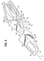
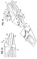
- a tooth system 10 comprises a point 12, adapter 14 and lock 16 (Figs. 1-10).
- the adapter 14 preferably includes a forwardly projecting nose 18 and a mounting end 21 in the form of a pair of rearwardly extending legs 22 (Figs. 1, 2, and 9-10).
- the legs 22 are adapted to straddle the digging edge 23 of an excavator and be welded in place.
- the mounting end could be different to attach the adapter in other ways, such as by a mechanical attachment or being integrally cast with the digging edge.
- the adapter could be attached to a second adapter or the like, which is then secured to the digging edge.
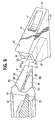
- the nose is generally wedge shaped and formed by converging walls 24, 26, sidewalls 28, 30, and a front bearing surface 32.
- Bearing surface 32 is adapted to receive axially directed loads applied to the wear member 12.
- the converging walls 24, 26 are preferably formed with a gentle transverse curve for enhanced strength and durability (Figs. 3 and 8), although they could be flat, provided with a greater curvature, or formed with another configuration.
- the sidewalls 28, 30 extend in generally parallel planes, although preferably with a slight taper. However, the sidewalls could be formed with a substantial inclination if desired.
- the transition edges between the converging walls and the sidewalls are generally rounded to minimize the concentration of stress at these locations.
- the sidewalls 28, 30 of the nose 18 are each formed with a flank 34 and a rail 35 having an outer surface 36 and a lateral surface 37 (Figs. 2, 3, 4 and 9).
- the rails 35 extend rearward in substantially parallel planes (i.e., with the rearward extension of the sidewalls), they diverge from each other as they extend rearward.
- one rail 35a extends from bearing surface 32 in a rearward direction that is substantially parallel to the rearward extension of converging wall 26, and one rail 35b extends rearwardly from bearing surface 32 in a direction that is substantially parallel to converging wall 24. In this way, the rails 35a and 35b diverge in generally vertical directions as they extend rearward.
- the rails are preferably formed with linear faces and generally constant depths and widths, primarily for easier manufacturing. However, other configurations are possible.
- one rail extends adjacent and substantially parallel to each converging wall 24, 26. Accordingly, an outside edge of each converging wall 24, 26 defines the top or bottom of the adjacent rail while lateral surface 37 extends generally parallel to the rearward extension of the converging wall. Nevertheless, variations are possible.
- the lateral surfaces may have a non-linear shape or an extension that is not parallel to the converging wall.
- the rails may be spaced from the converging walls such that they could have a second lateral surface (not shown) apart from the converging walls 24, 26.
- the outer surface 36 of each rail 35 is substantially vertical.
- the lateral surface 37 and flank 34 are inclined to form a generally V-shaped recess 40 (Figs. 3 and 8). Accordingly, the lateral surface 37 and flank 34 each present a surface area that is transverse to vertical to form primary bearing surfaces for vertical and lateral loads applied to the point 12.
- the converging walls 24, 26 form secondary bearing surfaces that may contact the socket under heavy loading or after wearing of the parts.
- Each lateral surface 37 is preferably set at an angle of 75 to 115 degrees relative to its respective flank 34, and most preferably at an angle of 95 degrees. Nevertheless, other angles could be used.
- the flanks 34 are generally triangular in shape such that they expand as they extend rearward to form an increasingly greater portion of each sidewall 28, 30.
- the point 12 has a generally wedge-shaped configuration defined by converging walls 43, 45 and sidewalls 47, 49 (Figs. 1-10).
- the converging walls 43, 45 narrow to form a forwardly projecting digging edge 51.
- a rearwardly opening socket 53 is provided to receive the adapter nose 18.
- the socket 53 is preferably shaped to matingly receive the adapter nose 18 (Figs. 5, 6 and 8). Accordingly, the socket is defined by converging surfaces 55, 57, side surfaces 59, 61, and a front surface 63.
- Each side surface 59, 61 is formed with a groove 65 and an inwardly projecting ridge or protrusion 67.
- the grooves 65 are shaped to receive the rails 35 on the adapter nose.
- the grooves 65 are preferably formed to extend along opposite converging surfaces 55, 57.
- the protrusions 67 each define a lateral surface 69 and an inner surface 71 that oppose and bear against lateral surface 37 and flank 34, respectively.
- lateral surface 69 and inner surface 71 form primary bearing surfaces for generally vertically applied loads
- the converging surfaces 55, 57 form secondary bearing surfaces that may contact the nose under heavy loading or after wearing of the parts.
- the front surface 63 is adapted to abut bearing surface 32 during axial loading.
- a rearwardly extending nose could be provided on the point to be received in a socket defined in the adapter.
- the socket and nose constructions could be reversed so that internal rails (not shown) could be provided in the socket with mating grooves provided on the nose (not shown).
- the point 12 On account of the diverging rails 35 and grooves 65, the point 12 must be turned or rotated as it is fit onto the adapter nose 18. In the preferred construction, the point rotates on the order of an eighth of a turn as it is installed. As a result, the point fits onto the adapter nose in much the same way as if the point and adapter were formed with helical threads rather than with straight rails and grooves.
- the point 12 is mounted to the nose 18 by first orienting the point 12 with respect to the nose 18 so that the rear portion 73 of each groove 65 is located adjacent to the front portion 75 of a corresponding rail 35 in order to receive the rail, as shown in Fig. 9.
- Fig. 10 shows the point 12 mounted on the nose 18 with the rails 35 fully inserted into the grooves 65 of socket 53.
- the present invention thus achieves certain advantages provided by the earlier wear assemblies provided with helical threads (e.g., U.S. Patent No. 4,353,532), but with a simpler and less expensive geometry to manufacture.
- the opposing rails of the present invention are easier to cast than the helical thread assemblies.
- the use of larger rails and grooves instead of sharper helical grooves lowers the stress risers in the nose for enhanced strength and durability.
- the present invention also achieves other advantages over the conventional helical thread assemblies.
- the present invention does not use a conical base for the nose, but rather uses a more slender profile wedge shape.
- the height of the nose (between the top and bottom surface) is not restricted by a conical base, and therefore the height of the nose may be adjusted according to need.
- the nose of the present invention may therefore be used to form tooth systems with more slender profiles than those provided with helical threads.
- the more slender profile tooth system provides for better penetration during digging and requires less metal to make.
- the degree of twist can be varied by changing the angle defining the divergence of the rails. In general, the greater the angle, the greater the amount of twist the point undergoes during installation and removal.
- the point 12 is stably positioned on the adapter nose 18.
- a centrally applied vertical load P1 on the free end 51 of the point 12 generates a smaller ejection force on account of the horizontal components of the reaction forces A1 and B 1 (Fig. 11).
- a central downward load P1 on the free end 51 of the point 12 generates reaction forces A1 and B1 at the tip and base of the nose 18.
- the vertical component of reaction force A1 is generally the same as the load P1 plus the vertical component of reaction force B1.
- the horizontal component of reaction force B1 is rearwardly directed to push the point onto the adapter rather than eject it.
- This holding or tightening force then at least partially offsets the ejection force due to the horizontal component of reaction force A1. While loads with vertical components applied to different parts of the point 12 may not always create the noted tightening force, the effect will occur under normal loads for a significant advantage.
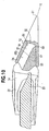
- the front free end 42 of the nose 18a is formed to have a generally rectangular configuration with upper and lower stabilizing flats 44, 46 (Figs. 12 and 13 ).
- the substantially parallel flats may be inclined to the longitudinal axis for up to about seven degrees for drafting purposes. While the flats may be inclined at greater angles, their stabilizing function tends to decrease with an increasing inclination.
- the socket 53a of point 12a includes a pair of front end stabilizing flats 78, 79 that engage flats 44, 46 on the adapter nose 18a.
- the front end of the socket is preferably given a generally rectangular configuration to mate with the front end of the nose, although shapes other than rectangular for the front ends of the nose and socket are possible.
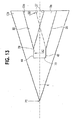
- a centrally applied downward load P2 on the free end of the point 12a creates a substantially vertical reaction force A2 with generally no horizontal component acting as an ejection force (Fig. 13).
- the inclination of the rails generate a horizontal component with a holding force at the base end of the point rather than an ejection force.
- the overall effect of the bearing surfaces i.e., the flats and the rails
- This construction provides a substantial improvement in point stability. The generation of the resultant tightening forces will lessen loading on the lock pin and reduce the risk of point loss.
- the extreme fibers of the upper and lower converging walls 2a, 2b of the nose 2 tend to have high stress levels under vertical loading because of the tendency of such loads to bend the nose.
- the outer converging surfaces form the primary bearing surfaces as well as undergoing the highest stress levels. As a result, these surfaces move and rub against the socket walls and experience a high degree of wearing under heavy loading:
- the rails 35 and flanks 34 form the primary bearing surfaces. Since the bearing surfaces are closer to the central horizontal plane of the tooth system, wearing of these surfaces has less affect on the ability of the nose to withstand high bending loads than wearing of the outer converging walls.
- the tooth system of the present invention is a stronger and more durable assembly.
- a smaller tooth system made in accordance with the present invention which requires less metal and has better penetration, can replace bigger conventional tooth systems.
- this reduction of wear in the extreme fibers will enable the section modulus to remain nearly the same throughout the life of the nose to maintain nose strength.
- the front end of the nose and corresponding socket can actually be wider than the rear end of the nose; that is, the sidewalls can be tapered to diverge slightly at an angle up to about 5 degrees as they extend forward.
- the nose can be provided with longitudinally extending rails 80 that include outer faces 81 and lateral bearing faces 83 (Fig. 14).
- the lateral bearing surfaces 83 are generally parallel to each other and to the longitudinal axis X of the tooth.
- the depth of the rails preferably increases as the rails extend rearward; that is the converging walls of the nose form the upper or lower surfaces of the respective rails 80 even though the lateral surfaces 83 extend rearwardly in an orientation that is generally parallel to the longitudinal axis of the tooth. Nevertheless, the rails could have a constant depth and simply be spaced from the respective converging wall. Without the divergence of the rails, the point is not rotated onto the adapter nose.
- the rails still continue to provide a stabilizing surface (as compared to the conventional tooth system) that reduces the stresses in the extreme fibers of the converging walls and, as discussed above, reduces the wearing of the bearing faces on resisting the bending forces.
- the use of only two rails that form a generally Z-shaped cross section improves the noted loading and wearing benefits for a reduced amount of material.
- This embodiment can further be used when twisting of the point during installation is not desired or possible.
- the points could be welded to a plate and the assembly then mounted collectively to the projecting adapter noses along the digging edge.
- the nose and points are preferably formed to be rotationally symmetrical about the longitudinal axis X so that the points can be reversibly mounted on the nose. Nevertheless, asymmetrical nose and/or points could be used in this invention.
- the point and adapter assembly of the present invention can be used with a wide variety of different locks to resist removal of the point from the adapter. Because the lock 16 withstands compression forces at least partially in lieu of shear forces (and thus experiences reduced shear loading) in resisting the ejection of point 12 from nose 18, the lock need not be as robust as locks used with other conventional point and adapter assemblies applying substantially only shear loads on the locks.
- the placement of the lock 16 is preferably along one side of the nose 18, as shown in Figs. 1 and 2.
- a lock could be provided at other locations including a vertical or horizontal central passage (such as in conventional tooth systems).
- any conventional lock used to secure points to the adapters including solid lock pins, pins with take-up elastomers, or locks with rigid casings such as disclosed in U.S. Patent No. 5,469,648 to Jones et al. could be used in conjunction with this invention.
- Fig. 2 shows a lock 16 in the form of a drive through lock pin that is received in a vertical channel 89 in the side of the nose.
- the point is provided with at least one rearwardly extending ear 91 having an inwardly extending lug 93 to engage the rear side of the pin and retain the point to the adapter.
- an ear and lug is provided on both sides of the point (not shown) so that the' point can be reversible mounted in either of 180 degree positions. While the channel and pin are shown with a linear configuration, they could be curved as in U.S. Patent No. 4,965,945 to Emrich.
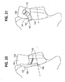
- a tapered locking pin 16' is provided to secure the point to the adapter.
- a nose 18' has a tapered vertical channel 103 along one side for receiving a tapered locking pin 16'.
- the lock can be tapered along its entire length, it only needs to be tapered along a substantial portion of its length.
- the front surface 104 gradually arcs rearward the entire length of the lock so that the taper extends along substantially the entire length of the lock.
- Fig. 15 shows a blind channel that extends only partially through the nose and tapers to a closed end 105 at the bottom. Nevertheless, an open channel that extends entirely through the adapter could be used with the tapered pin if desired.
- the locking pin 16' has a corresponding tapered shape to fit within the tapered channel 103 (Figs. 15-18).
- the locking pin 16' preferably terminates in a narrow point 106.
- the pin 16' has a bearing portion 107 that has a front surface 104 for engaging the shoulder 109 of the nose (i.e., the front edge of channel 103) and a rear surface for engaging the lug 93' of the ear 91'.
- the locking pin 16' has a web 111 that extends rearward to strengthen the lock against axial forces and ensure proper insertion of the lock pin.
- the lock pin could have a uniform circular, rectangular or other shape as desired.
- the nose 18' defines a slot 113 in communication with the channel 103 to allow the lug 93' and ear 91' to pass along the side of the nose to a position within the channel.
- the pin 16' defines a recess 115 behind the rear surface 107 and proximate to the web 111 for receiving a portion of the lug 93'.
- the locking pin 16' may be formed from any conventional method, such as by casting.
- the lock pin 16' is preferably retained in the channel 103 through the use of a locking member. In the embodiment shown in Figs. 15-18, the locking member is a set screw 121.
- the channel 103 preferably includes an indent 125 for receiving the set screw to better retain the locking pin in the channel 103, but the indent is not required.
- the set screw 121 is tightened.
- the set screw 121 may be upset at the end or provided with a retaining ring or other means to prevent the set screw from becoming disassociated from the lock pin.
- the lock pin preferably includes an overhanging shelf 123, which protects the set screw from wear.
- a spring (not shown) can also be associated with the set screw to inhibit loosening during vibration.
- the lock pin 16' could also be used in conjunction with other wear assemblies. For example, as shown in Fig. 19, the lock pin could be used to retain a point 128 with a simple wedge shaped socket, ears 132, lugs 130.
- a tapered lock pin in accordance with the present invention could also be used in tooth systems having vertical or horizontal central holes (not shown).
- lock pins 131, 133 have tapered constructions that could be used in place of lock pin 16'.
- Lock pin 131 has a detent 134 that is biased outward at one end 136 by an elastomer 138 to fit under a ledge 140 defined in the adapter nose.
- the detent preferably has a projecting contact surface 136a to form a secure engagement with ledge 140.
- the detent 134 is preferably adhered to elastomer 138 which in turn is adhered in a pocket of the cast body 135.
- the detent 141 is biased to move along an arcuate path 143 by an elastomer 145.
- the free end 147 of the detent 141 engages a notch 149 or the like defined in the adapter nose.
- the adapter nose includes a narrow slot (not shown) whereby a tool can be inserted to push the detents into the elastomers to release the detents 134, 141 when removal of the locks is desired.
- a tapered pin is easier to install and remove than a conventional drive-through pin.
- the tapered surfaces allow the locking pin to be inserted without encountering any resistance from the surface of the point or nose until the locking pin is almost entirely inserted into the channel.
- the tapered locking pin may be removed using a pry tool, rather than being hammered because the pin need only travel a short distance before it is free from the channel. Once free, the lock pin may be removed by hand.
- the tapered lock pin of the present invention is that the force required to remove the lock with the lock member engaged is greater than that required to remove a conventional drive-through locking pin.
- the tapered locking pin is prevented from moving downward because the groove narrows or terminates, and the locking member, such as the set screw, prevents the lock pin from moving upward out of the groove.
- the lock pin thus relies on mechanical interference, rather than a tight fit, to prevent removal of the tapered locking pin once installed.
Applications Claiming Priority (2)
| Application Number | Priority Date | Filing Date | Title |
|---|---|---|---|
| US09/899,535 US6735890B2 (en) | 2001-07-06 | 2001-07-06 | Wear assembly |
| EP02749631A EP1404926B1 (de) | 2001-07-06 | 2002-07-03 | Verschleissanordnung |
Related Parent Applications (2)
| Application Number | Title | Priority Date | Filing Date |
|---|---|---|---|
| EP02749631A Division EP1404926B1 (de) | 2001-07-06 | 2002-07-03 | Verschleissanordnung |
| EP02749631.4 Division | 2002-07-03 |
Publications (3)
| Publication Number | Publication Date |
|---|---|
| EP1637661A2 true EP1637661A2 (de) | 2006-03-22 |
| EP1637661A3 EP1637661A3 (de) | 2006-04-05 |
| EP1637661B1 EP1637661B1 (de) | 2010-03-24 |
Family
ID=25411164
Family Applications (3)
| Application Number | Title | Priority Date | Filing Date |
|---|---|---|---|
| EP05027595A Expired - Lifetime EP1637661B1 (de) | 2001-07-06 | 2002-07-03 | Verschleissanordnung |
| EP02749631A Expired - Lifetime EP1404926B1 (de) | 2001-07-06 | 2002-07-03 | Verschleissanordnung |
| EP05027594A Expired - Lifetime EP1637660B1 (de) | 2001-07-06 | 2002-07-03 | Verschleissteil und -anordnung |
Family Applications After (2)
| Application Number | Title | Priority Date | Filing Date |
|---|---|---|---|
| EP02749631A Expired - Lifetime EP1404926B1 (de) | 2001-07-06 | 2002-07-03 | Verschleissanordnung |
| EP05027594A Expired - Lifetime EP1637660B1 (de) | 2001-07-06 | 2002-07-03 | Verschleissteil und -anordnung |
Country Status (22)
| Country | Link |
|---|---|
| US (3) | US6735890B2 (de) |
| EP (3) | EP1637661B1 (de) |
| JP (2) | JP4295085B2 (de) |
| KR (1) | KR101024445B1 (de) |
| CN (3) | CN1837518B (de) |
| AR (3) | AR034737A1 (de) |
| AT (3) | ATE450663T1 (de) |
| AU (2) | AU2002320131B2 (de) |
| BR (3) | BR0210755B1 (de) |
| CA (1) | CA2451309C (de) |
| DE (4) | DE60235777D1 (de) |
| DK (2) | DK1637660T3 (de) |
| ES (3) | ES2337798T3 (de) |
| HK (2) | HK1068659A1 (de) |
| MX (2) | MX343761B (de) |
| MY (3) | MY143623A (de) |
| NO (1) | NO336703B1 (de) |
| NZ (2) | NZ545677A (de) |
| PE (1) | PE20030264A1 (de) |
| PT (2) | PT1637661E (de) |
| WO (1) | WO2003004783A2 (de) |
| ZA (1) | ZA200400018B (de) |
Families Citing this family (118)
| Publication number | Priority date | Publication date | Assignee | Title |
|---|---|---|---|---|
| US20040060207A1 (en) * | 2002-09-27 | 2004-04-01 | Livesay Richard E. | Mechanically attached tip assembly |
| AR046804A1 (es) * | 2003-04-30 | 2005-12-28 | Esco Corp | Conjunto de acoplamiento desenganchable para pala de excavadora |
| ITUD20040021A1 (it) * | 2004-02-10 | 2004-05-10 | Italricambi Srl | Dente per benne di escavatori o simili |
| US20060010725A1 (en) * | 2004-07-14 | 2006-01-19 | Jackson Michael J | Excavating tooth and adapter |
| US20080201997A1 (en) * | 2004-08-02 | 2008-08-28 | Wundowie Foundry Pty Ltd. | Tooth and Adaptor Assembly |
| AU2005203574C1 (en) * | 2005-08-10 | 2013-11-07 | Cutting Edges Equipment Parts Pty Ltd | Adaptor, intermediate adaptor and tooth assembly or construction |
| CN101253298B (zh) * | 2005-08-30 | 2012-07-18 | 爱斯科公司 | 用于挖掘机的耐磨损总成 |
| MY149408A (en) * | 2005-08-30 | 2013-08-30 | Esco Corp | Wear assembly for excavating machines |
| CA2523513A1 (en) * | 2005-10-14 | 2007-04-14 | Amsco Cast Products (Canada) Inc. | Tooth and adaptor assembly for a dipper bucket |
| JOP20190303A1 (ar) * | 2006-02-17 | 2017-06-16 | Esco Group Llc | تجميعة مقاومة للتآكل |
| AU2012200752C1 (en) * | 2006-02-17 | 2016-10-06 | Esco Group Llc | Wear Assembly |
| ES2904591T3 (es) | 2006-03-30 | 2022-04-05 | Esco Group Llc | Conjunto de desgaste |
| PE20080597A1 (es) * | 2006-04-24 | 2008-05-17 | Esco Corp | Montaje de desgaste |
| CN101466901B (zh) * | 2006-06-16 | 2011-12-14 | 爱斯科公司 | 将磨损部件紧固在土工作业设备上的锁 |
| US7658024B2 (en) * | 2006-07-06 | 2010-02-09 | H&L Tooth Company | Universal digging tooth attachment apparatus |
| EP2589711B1 (de) * | 2006-08-16 | 2019-09-18 | Caterpillar Inc. | Zahnsystem zur Bodenbearbeitung |
| CA2719712C (en) | 2007-03-29 | 2013-11-19 | Cqms Pty Ltd | Mounting of wear members |
| WO2008119103A1 (en) | 2007-04-03 | 2008-10-09 | Cqms Pty Ltd | A mounting pin assembly for an excavator wear member |
| BR122015006403B1 (pt) * | 2007-05-10 | 2018-10-23 | Esco Corporation | montagem de desgaste para equipamento de escavação |
| US8061064B2 (en) | 2007-05-10 | 2011-11-22 | Esco Corporation | Wear assembly for excavating equipment |
| CA2597277C (en) * | 2007-08-14 | 2011-11-08 | Neil Douglas Bentley | Retainer pin and tooth for tooth and adaptor assembly |
| CA2612341A1 (en) * | 2007-11-27 | 2009-05-27 | Black Cat Blades Ltd. | Ground engaging tool blade |
| NO334868B1 (no) | 2008-04-10 | 2014-06-23 | Komatsu Kvx Llc | Skuffesliteenhet omfattende en slitedel og en adapter |
| AU2009238226C1 (en) * | 2008-04-18 | 2015-04-02 | Cqms Pty Ltd | A lock assembly for an excavator wear member |
| US20090277050A1 (en) * | 2008-05-06 | 2009-11-12 | Esco Corporation | Wear Assembly For Excavating Equipment |
| GB2461910B (en) * | 2008-07-17 | 2012-07-18 | Bamford Excavators Ltd | Method of operating an apparatus |
| WO2010089423A1 (es) * | 2009-02-06 | 2010-08-12 | Metalogenia, S.A. | Sistema de acoplamiento entre elemento de desgaste y adaptador para maquinas excavadoras y similares, así como componentes del mismo |
| PL3184701T3 (pl) * | 2009-03-23 | 2023-06-19 | Black Cat Wear Parts Ltd. | W pełni stabilizowane mocowanie zęba koparki |
| US7980011B2 (en) * | 2009-03-23 | 2011-07-19 | Black Cat Blades Ltd. | Fully stabilized excavator tooth attachment |
| US9359744B2 (en) * | 2009-08-05 | 2016-06-07 | H&L Tooth Company | Multipiece wear assembly |
| CA2778973C (en) * | 2009-10-30 | 2016-11-15 | Esco Corporation | Wear assembly for excavating equipment |
| AP3457A (en) | 2009-12-11 | 2015-12-31 | Cqms Pty Ltd | A lock assembly for an excavator wear member |
| CA2783700A1 (en) * | 2009-12-11 | 2011-06-16 | Cqms Pty Ltd | A wear member assembly |
| USD634605S1 (en) * | 2010-05-24 | 2011-03-22 | Cqms Pty Ltd | Locking pin assembly for an excavator wear member |
| USRE45710E1 (en) * | 2009-12-11 | 2015-10-06 | CQMS Pty Limited | Locking pin assembly for an excavator wear member |
| US9091042B2 (en) * | 2009-12-24 | 2015-07-28 | Cqms Pty Ltd | Wear assembly for an excavator bucket |
| US9185335B2 (en) | 2009-12-28 | 2015-11-10 | Thomson Licensing | Method and device for reception of video contents and services broadcast with prior transmission of data |
| JOP20200150A1 (ar) | 2011-04-06 | 2017-06-16 | Esco Group Llc | قطع غيار بأوجه مقواه باستخدام عملية التقسية المصلدة والطريقة والتجميع المرافق للتصنيع |
| US9757730B2 (en) * | 2011-07-06 | 2017-09-12 | Joy Mm Delaware, Inc. | Pick retainer |
| US8890672B2 (en) | 2011-08-29 | 2014-11-18 | Harnischfeger Technologies, Inc. | Metal tooth detection and locating |
| WO2013033751A1 (en) | 2011-09-08 | 2013-03-14 | Cqms Pty Ltd | A lock assembly for an excavator wear member |
| CN102443954B (zh) * | 2011-09-27 | 2014-07-02 | 东华大学 | 一种用碳长丝包芯纱纬编的电磁屏蔽针织物及其用途 |
| USD706312S1 (en) | 2011-10-07 | 2014-06-03 | Caterpiller, Inc. | Tip for a ground engaging machine implement |
| USD706307S1 (en) | 2011-10-07 | 2014-06-03 | Caterpillar, Inc. | Adapter for a ground engaging machine implement |
| US9062436B2 (en) | 2011-10-07 | 2015-06-23 | Caterpillar Inc. | Implement tooth assembly with tip and adapter |
| US8943717B2 (en) | 2011-10-08 | 2015-02-03 | Caterpillar Inc. | Implement tooth assembly with tip and adapter |
| USD707264S1 (en) | 2011-10-07 | 2014-06-17 | Caterpillar Inc. | Adapter for a ground engaging machine implement |
| USD706840S1 (en) | 2011-10-07 | 2014-06-10 | Caterpillar, Inc. | Tip for a ground engaging machine implement |
| US9057177B2 (en) | 2011-10-08 | 2015-06-16 | Caterpillar Inc. | Implement tooth assembly with tip and adapter |
| US8943716B2 (en) | 2011-10-10 | 2015-02-03 | Caterpillar Inc. | Implement tooth assembly with tip and adapter |
| EP2581506A1 (de) * | 2011-10-14 | 2013-04-17 | Caterpillar Work Tools B. V. | Verschleißpaket für ein Abbruchwerkzeug |
| BR122020005555B1 (pt) * | 2011-11-23 | 2021-08-10 | Esco Group Llc | Membro de desgaste para equipamento de acoplamento com a terra |
| IN2014KN01273A (de) | 2011-12-08 | 2015-10-16 | Cqms Pty Ltd | |
| US8959807B2 (en) * | 2011-12-13 | 2015-02-24 | Caterpillar Inc. | Edge protector for ground engaging tool assembly |
| JO3717B1 (ar) | 2012-01-31 | 2021-01-31 | Esco Group Llc | مادة مقاومة للتآكل ونظام وطريقة لصنعها |
| EA030737B1 (ru) * | 2012-02-17 | 2018-09-28 | Эско Корпорейшн | Сменный износный блок |
| EP2711472B1 (de) * | 2012-09-21 | 2017-07-19 | Liebherr-Mining Equipment Colmar SAS | Flügelblech für eine Erdbaumaschinenschaufel, und Erdbaumaschine |
| US9926687B2 (en) | 2013-03-25 | 2018-03-27 | Keech Castings Australia Pty Limited | Lock assembly |
| USD728636S1 (en) | 2013-08-01 | 2015-05-05 | Caterpillar Inc. | Coupler and tip for a ground engaging machine implement |
| USD728637S1 (en) | 2013-08-01 | 2015-05-05 | Caterpillar Inc. | Tip for a ground engaging machine implement |
| USD728635S1 (en) | 2013-08-01 | 2015-05-05 | Caterpillar Inc. | Coupler for a ground engaging machine implement |
| EP3572442B1 (de) | 2013-12-23 | 2021-04-07 | BASF South East Asia Pte. Ltd. | Neuartige anti-agglomerante zur polyisobutylenherstellung |
| PE20161422A1 (es) | 2014-04-28 | 2017-01-08 | Metalogenia Res And Tech S L | Diente y adaptador para la union del diente a una maquina de trabajo |
| CA2943615C (en) * | 2015-02-13 | 2018-06-05 | Black Cat Blades Ltd. | Wear members for excavation implements |
| MY190902A (en) * | 2015-02-13 | 2022-05-18 | Esco Group Llc | Monitoring ground-engaging products for earth working equipment |
| US9611625B2 (en) | 2015-05-22 | 2017-04-04 | Harnischfeger Technologies, Inc. | Industrial machine component detection and performance control |
| USD774567S1 (en) | 2015-08-12 | 2016-12-20 | Caterpillar Inc. | Tip for a ground engaging machine implement |
| USD774108S1 (en) | 2015-08-12 | 2016-12-13 | Caterpillar Inc. | Tip for a ground engaging machine implement |
| USD774564S1 (en) | 2015-08-12 | 2016-12-20 | Caterpillar Inc. | Tip for a ground engaging machine implement |
| USD775242S1 (en) | 2015-08-12 | 2016-12-27 | Caterpillar Inc. | Tip for a ground engaging machine implement |
| USD774109S1 (en) | 2015-08-12 | 2016-12-13 | Caterpillar Inc. | Tip for a ground engaging machine implement |
| USD774110S1 (en) | 2015-08-12 | 2016-12-13 | Caterpillar Inc. | Tip for a ground engaging machine implement |
| USD774566S1 (en) | 2015-08-12 | 2016-12-20 | Caterpillar Inc. | Tip for a ground engaging machine implement |
| USD774565S1 (en) | 2015-08-12 | 2016-12-20 | Caterpillar Inc. | Tip for a ground engaging machine implement |
| USD775241S1 (en) | 2015-08-12 | 2016-12-27 | Caterpillar Inc. | Tip for a ground engaging machine implement |
| USD775243S1 (en) | 2015-08-12 | 2016-12-27 | Caterpillar Inc. | Tip for a ground engaging machine implement |
| USD775673S1 (en) | 2015-08-12 | 2017-01-03 | Caterpillar Inc. | Tip for a ground engaging machine implement |
| USD775240S1 (en) | 2015-08-12 | 2016-12-27 | Caterpillar Inc. | Tip for a ground engaging machine implement |
| US10030368B2 (en) | 2015-10-06 | 2018-07-24 | Hensley Industries, Inc. | Excavating tooth assembly with locking pin assembly |
| CN112726726B (zh) | 2015-11-12 | 2022-07-22 | 久益环球地表采矿公司 | 用于检测重型机械磨损的方法和系统 |
| US10167720B2 (en) * | 2016-01-13 | 2019-01-01 | Caterpillar Paving Products Inc. | Milling tool holder |
| US10508418B2 (en) | 2016-05-13 | 2019-12-17 | Hensley Industries, Inc. | Stabilizing features in a wear member assembly |
| CA3024513A1 (en) * | 2016-06-13 | 2017-12-21 | Esco Group Llc | Handling system for ground-engaging wear parts secured to earth working equipment |
| US10407880B2 (en) * | 2016-06-24 | 2019-09-10 | Caterpillar Inc. | Wear member retention system for an implement |
| CN106238147A (zh) * | 2016-08-30 | 2016-12-21 | 浙江华莎驰机械有限公司 | 一种铲刀形废品处理用齿 |
| CN114277881B (zh) | 2016-09-09 | 2023-11-17 | 久益环球地表采矿公司 | 地面接合工具锁定系统 |
| USD805562S1 (en) | 2016-12-15 | 2017-12-19 | Caterpillar Inc. | Adapter for a ground engaging machine implement |
| USD806758S1 (en) | 2016-12-15 | 2018-01-02 | Caterpillar Inc. | Tip for a ground engaging machine implement |
| USD806139S1 (en) | 2016-12-15 | 2017-12-26 | Caterpillar Inc. | Adapter for a ground engaging machine implement |
| USD803902S1 (en) | 2016-12-15 | 2017-11-28 | Caterpillar Inc. | Tip for a ground engaging machine implement |
| USD803275S1 (en) | 2016-12-15 | 2017-11-21 | Caterpillar Inc. | Tip for a ground engaging machine implement |
| USD803898S1 (en) | 2016-12-15 | 2017-11-28 | Caterpillar Inc. | Tip for a ground engaging machine implement |
| USD803900S1 (en) | 2016-12-15 | 2017-11-28 | Caterpillar Inc. | Tip for a ground engaging machine implement |
| USD806759S1 (en) | 2016-12-15 | 2018-01-02 | Caterpillar Inc. | Tip for a ground engaging machine implement |
| USD803899S1 (en) | 2016-12-15 | 2017-11-28 | Caterpillar Inc. | Tip for a ground engaging machine implement |
| USD840441S1 (en) | 2016-12-15 | 2019-02-12 | Caterpillar Inc. | Adapter for a ground engaging machine implement |
| USD803897S1 (en) | 2016-12-15 | 2017-11-28 | Caterpillar Inc. | Tip for a ground engaging machine implement |
| USD803901S1 (en) | 2016-12-15 | 2017-11-28 | Caterpillar Inc. | Tip for a ground engaging machine implement |
| USD806141S1 (en) | 2016-12-15 | 2017-12-26 | Caterpillar Inc. | Adapter for a ground engaging machine implement |
| USD806140S1 (en) | 2016-12-15 | 2017-12-26 | Caterpillar Inc. | Adapter for a ground engaging machine implement |
| USD805112S1 (en) | 2016-12-15 | 2017-12-12 | Caterpillar Inc. | Tip for a ground engaging machine implement |
| USD806142S1 (en) | 2016-12-15 | 2017-12-26 | Caterpillar Inc. | Adapter for a ground engaging machine implement |
| USD803274S1 (en) | 2016-12-15 | 2017-11-21 | Caterpillar Inc. | Tip for a ground engaging machine implement |
| US20180207780A1 (en) * | 2017-01-25 | 2018-07-26 | Lu Kang Hand Tools Industrial Co., Ltd. | Detachable hand tool made of different materials |
| USD832310S1 (en) | 2017-08-30 | 2018-10-30 | Caterpillar Inc. | Adapter for a ground engaging machine implement |
| USD918965S1 (en) * | 2018-06-19 | 2021-05-11 | Hensley Industries, Inc. | Ground engaging wear member |
| USD905765S1 (en) | 2019-03-07 | 2020-12-22 | Caterpillar Inc. | Adapter for a ground engaging machine implement |
| USD888785S1 (en) | 2019-03-07 | 2020-06-30 | Caterpillar Inc. | Adapter for a ground engaging machine implement |
| USD894971S1 (en) | 2019-04-26 | 2020-09-01 | Caterpillar Inc. | Tip for a ground engaging machine implement |
| USD897379S1 (en) * | 2019-04-26 | 2020-09-29 | Caterpillar Inc. | Tip for a ground engaging machine implement |
| KR102080913B1 (ko) * | 2019-09-20 | 2020-02-24 | 주식회사 건화 | 버켓 |
| EP4034717A4 (de) * | 2019-09-23 | 2023-10-04 | CQMS Pty Ltd | Vorrichtung zum entfernen eines verschleissteils |
| US11634892B2 (en) | 2019-11-27 | 2023-04-25 | Hensley Industries, Inc. | Excavating tooth assembly with releasable lock pin assembly |
| USD908144S1 (en) * | 2020-01-06 | 2021-01-19 | Pengo Corporation | Excavating tooth |
| USD945499S1 (en) | 2020-11-18 | 2022-03-08 | Caterpillar Inc. | Adapter for a ground engaging machine implement |
| USD945498S1 (en) | 2020-11-18 | 2022-03-08 | Caterpillar Inc. | Adapter for a ground engaging machine implement |
| EP4137644A1 (de) * | 2021-08-18 | 2023-02-22 | Metalogenia Research & Technologies S.L. | Schutzelement für ein verschleisselement von erdbewegungsmaschinen |
| CN114232722A (zh) * | 2021-12-31 | 2022-03-25 | 常州市聚科金属结构件有限公司 | 一种方便更换铲片的挖斗 |
Citations (1)
| Publication number | Priority date | Publication date | Assignee | Title |
|---|---|---|---|---|
| US2987838A (en) | 1957-08-05 | 1961-06-13 | Elton Stratton | Excavating tooth |
Family Cites Families (71)
| Publication number | Priority date | Publication date | Assignee | Title |
|---|---|---|---|---|
| US805004A (en) * | 1905-02-03 | 1905-11-21 | Andrew M Cupples | Tooth for excavator-buckets. |
| US821215A (en) | 1905-07-18 | 1906-05-22 | John C Cantlebery | Tooth for steam-shovels. |
| US887984A (en) * | 1907-04-05 | 1908-05-19 | Taylor Iron & Steel Company | Tooth for excavating-shovels. |
| US888047A (en) * | 1907-12-27 | 1908-05-19 | Taylor Iron And Steel Company | Tooth for excavating-shovels. |
| US995285A (en) * | 1911-01-18 | 1911-06-13 | Edward Louis Pemberton | Tooth for excavating-buckets. |
| US1188480A (en) * | 1914-06-26 | 1916-06-27 | American Manganese Steel Co | Tooth for dippers of excavating-machines. |
| US1544222A (en) * | 1921-10-22 | 1925-06-30 | American Hoist & Derrick Co | Dipper-tooth point for excavating shovels |
| US1485434A (en) * | 1922-11-14 | 1924-03-04 | Frog Switch & Mfg Company | Dipper tooth |
| US1729889A (en) | 1927-07-23 | 1929-10-01 | American Manganese Steel Co | Wedge-fit tooth point |
| US2040085A (en) | 1934-03-23 | 1936-05-12 | Bucyrus Erie Co | Dipper tooth |
| US2032875A (en) | 1934-06-09 | 1936-03-03 | American Manganese Steel Co | Laminated tooth point |
| US2145663A (en) | 1936-09-28 | 1939-01-31 | Nazro H Reynolds | Attachment means for digging teeth and excavating buckets and the like |
| US2124230A (en) * | 1937-03-08 | 1938-07-19 | H And L Corp | Detachable point for earth digging teeth |
| US2256488A (en) * | 1938-06-22 | 1941-09-23 | Daniels Murtaugh Company | Replaceable tooth for dippers |
| US2419677A (en) | 1945-02-10 | 1947-04-29 | Arthur W Danlels | Excavating tooth |
| US2483032A (en) | 1945-06-06 | 1949-09-27 | Electric Steel Foundry | Excavating tooth |
| US2896345A (en) | 1954-07-23 | 1959-07-28 | Electric Steel Foundry Co | Tooth assembly |
| US2846790A (en) | 1955-01-13 | 1958-08-12 | Electric Steel Foundry Co | Tooth assembly |
| US2982035A (en) * | 1958-04-28 | 1961-05-02 | Thomas C Whisler | Excavator tooth |
| US3082555A (en) | 1960-08-26 | 1963-03-26 | Esco Corp | Wear cap for excavating tooth |
| US3117386A (en) | 1961-03-07 | 1964-01-14 | Ferwerda Ray | Tooth arrangement for earth digging apparatus |
| US3496658A (en) | 1967-12-22 | 1970-02-24 | Esco Corp | Excavating tooth components |
| US3453756A (en) | 1968-03-13 | 1969-07-08 | Smith International | Reversible excavating tooth |
| DE2162474A1 (de) | 1971-12-16 | 1973-06-20 | Andre Aulfinger | Baggerzahn mit auswechselbarer zahnspitze |
| US4136469A (en) | 1975-02-21 | 1979-01-30 | Zepf Hans Rudolf | Shovel tooth |
| CH599403A5 (de) | 1976-04-12 | 1978-05-31 | Zepf Hans Rudolf | |
| US4404760A (en) | 1980-04-28 | 1983-09-20 | Esco Corporation | Excavating tooth |
| US4335532A (en) | 1980-04-28 | 1982-06-22 | Esco Corporation | Excavating tooth |
| US4326348A (en) | 1980-07-30 | 1982-04-27 | Esco Corporation | Excavating tooth assembly |
| US4391050A (en) | 1981-05-01 | 1983-07-05 | J. I. Case Company | Tooth assembly |
| US4481728A (en) | 1981-12-01 | 1984-11-13 | Abex Corporation | Dipper tooth tip and adapter |
| DE3315024A1 (de) | 1983-04-26 | 1984-10-31 | Liebherr-France S.A., Colmar-Cedex | Zahn fuer greifer, loeffel oder schaufeln von hydraulikbaggern, ladern oder dergleichen |
| US4470210A (en) | 1983-05-25 | 1984-09-11 | Esco Corporation | Mounting for excavating implement and method |
| US4577423A (en) | 1984-12-24 | 1986-03-25 | Esco Corporation | Excavating tooth system |
| CN86209610U (zh) * | 1986-11-29 | 1987-12-16 | 埃斯科公司 | 铲齿 |
| US4761900A (en) | 1986-12-04 | 1988-08-09 | Esco Corporation | Excavating tooth assembly |
| US5018283A (en) | 1989-08-04 | 1991-05-28 | Deere & Company | Loader bucket tooth |
| SE469561B (sv) | 1989-09-08 | 1993-07-26 | Rainer A Hilden | Anordning vid utbytbar tand |
| US5068986A (en) | 1990-08-30 | 1991-12-03 | Esco Corporation | Excavating tooth point particularly suited for large dragline buckets |
| US5152088A (en) | 1990-09-10 | 1992-10-06 | Esco Corporation | Excavating tooth point and method of replacement |
| US5074062A (en) | 1990-09-10 | 1991-12-24 | Esco Corporation | Method of replacing a worn excavating tooth point |
| US5152087A (en) | 1990-10-09 | 1992-10-06 | A. M. Logistic Corporation | Holding clamp and reversible earth working cutting teeth |
| US5148616A (en) | 1990-12-21 | 1992-09-22 | A.M. Logistics Corporation | Adaptor for earth working cutting teeth and holding clamp |
| US5088214A (en) * | 1991-01-17 | 1992-02-18 | Esco Corporation | Excavator wear edge |
| WO1993013272A1 (en) | 1991-12-20 | 1993-07-08 | Esco Corporation | Attachments for excavating bucket |
| US5177886A (en) | 1992-03-16 | 1993-01-12 | Caterpillar Inc. | Tooth with clearances in socket |
| US5469648A (en) | 1993-02-02 | 1995-11-28 | Esco Corporation | Excavating tooth |
| FR2708973B1 (fr) * | 1993-03-29 | 1995-10-27 | Pasqualini Charles | Dispositif et procédé de liaison entre des dents amovibles et des adapteurs formés aux extrémités d'outils et réceptacles en usage sur les engins de travaux publics. |
| US5272824A (en) * | 1993-05-10 | 1993-12-28 | Caterpillar Inc. | Tooth assembly with leaf spring retainer |
| SE504157C2 (sv) | 1994-03-21 | 1996-11-25 | Componenta Wear Parts Ab | Tandarrangemang; sammanfogning med sprint |
| US5423138A (en) * | 1994-04-04 | 1995-06-13 | Caterpillar, Inc. | Tip to adapter interface |
| AUPN174595A0 (en) * | 1995-03-15 | 1995-04-06 | Ani Corporation Limited, The | A mounting system |
| US5561925A (en) | 1995-07-25 | 1996-10-08 | Caterpillar Inc. | Tooth assembly and retaining mechanism |
| US5806216A (en) * | 1995-09-29 | 1998-09-15 | Caterpillar Inc. | Base edge cover for a bucket and apparatus for retaining same |
| US5653048A (en) * | 1995-11-06 | 1997-08-05 | Esco Corporation | Wear assembly for a digging edge of an excavator |
| US5564206A (en) | 1995-11-13 | 1996-10-15 | Gh Hensley Industries, Inc. | Self-adjusting tooth/adapter connection system for material displacement apparatus |
| US5718070A (en) | 1995-11-13 | 1998-02-17 | Gh Hensley Industries, Inc. | Self-adjusting tooth/adapter connection system for material displacement apparatus |
| CN1204376A (zh) * | 1995-12-11 | 1999-01-06 | 埃斯科公司 | 耐磨部件 |
| US5937550A (en) * | 1995-12-11 | 1999-08-17 | Esco Corporation | Extensible lock |
| US5666748A (en) * | 1995-12-11 | 1997-09-16 | Esco Corporation | Wear cap and components useable therewith |
| US5709043A (en) | 1995-12-11 | 1998-01-20 | Esco Corporation | Excavating tooth |
| ATE184670T1 (de) | 1996-07-01 | 1999-10-15 | Metalogenia Sa | Kupplungsverbindung für einen baggerzahn |
| CA2219036C (en) * | 1997-11-13 | 2001-09-04 | Quality Steel Foundries Ltd. | Coupling device for locking an excavation tooth onto an adaptor |
| US6030143A (en) | 1997-12-18 | 2000-02-29 | Esco Corporation | Locking pin for excavating equipment |
| US5987787A (en) * | 1998-02-11 | 1999-11-23 | Wright Equipment Company (Proprietary) Limited | Ground engaging tool components |
| US5956874A (en) * | 1998-05-07 | 1999-09-28 | Columbia Steel Casting Co., Inc. | Tooth assembly and lock system |
| US6047487A (en) | 1998-07-17 | 2000-04-11 | H&L Tooth Co. | Multipiece excavating tooth assembly |
| US6158917A (en) | 1999-02-23 | 2000-12-12 | Wolin; Robert H. | Retention mechanism for mounting pins |
| US6108950A (en) | 1999-03-08 | 2000-08-29 | Gh Hensley Industries, Inc. | Self-adjusting tooth/adapter connection system for material displacement apparatus |
| US6374521B1 (en) * | 1999-04-05 | 2002-04-23 | Trn Business Trust | Apparatus and method for coupling an excavation tooth assembly |
| FR2792343B1 (fr) | 1999-04-19 | 2001-06-22 | Charles Pasqualini | Dispositif de liaison entre des pieces d'usure aux extremites d'outils et receptacles en usage sur les engins et materiels de travaux publics |
-
2001
- 2001-07-06 US US09/899,535 patent/US6735890B2/en not_active Expired - Lifetime
-
2002
- 2002-07-03 AT AT05027594T patent/ATE450663T1/de active
- 2002-07-03 KR KR1020047000180A patent/KR101024445B1/ko active IP Right Grant
- 2002-07-03 JP JP2003510530A patent/JP4295085B2/ja not_active Expired - Lifetime
- 2002-07-03 AT AT05027595T patent/ATE462047T1/de active
- 2002-07-03 PT PT05027595T patent/PT1637661E/pt unknown
- 2002-07-03 CN CN2006100740567A patent/CN1837518B/zh not_active Expired - Lifetime
- 2002-07-03 DE DE60235777T patent/DE60235777D1/de not_active Expired - Lifetime
- 2002-07-03 BR BRPI0210755-4A patent/BR0210755B1/pt not_active IP Right Cessation
- 2002-07-03 BR BRPI0216017-0A patent/BR0216017B1/pt active IP Right Grant
- 2002-07-03 DK DK05027594.0T patent/DK1637660T3/da active
- 2002-07-03 MX MX2010001598A patent/MX343761B/es unknown
- 2002-07-03 DE DE60234652T patent/DE60234652D1/de not_active Expired - Lifetime
- 2002-07-03 ES ES05027594T patent/ES2337798T3/es not_active Expired - Lifetime
- 2002-07-03 NZ NZ545677A patent/NZ545677A/en not_active IP Right Cessation
- 2002-07-03 DE DE60220795T patent/DE60220795T2/de not_active Expired - Lifetime
- 2002-07-03 EP EP05027595A patent/EP1637661B1/de not_active Expired - Lifetime
- 2002-07-03 AT AT02749631T patent/ATE365249T1/de not_active IP Right Cessation
- 2002-07-03 ES ES02749631T patent/ES2287298T3/es not_active Expired - Lifetime
- 2002-07-03 CN CN2005100970649A patent/CN1800522B/zh not_active Expired - Lifetime
- 2002-07-03 WO PCT/US2002/019795 patent/WO2003004783A2/en active IP Right Grant
- 2002-07-03 NZ NZ530359A patent/NZ530359A/en not_active IP Right Cessation
- 2002-07-03 BR BRPI0216099-4B1A patent/BR0216099B1/pt active IP Right Grant
- 2002-07-03 CA CA002451309A patent/CA2451309C/en not_active Expired - Lifetime
- 2002-07-03 EP EP02749631A patent/EP1404926B1/de not_active Expired - Lifetime
- 2002-07-03 PT PT05027594T patent/PT1637660E/pt unknown
- 2002-07-03 MX MXPA03012025A patent/MXPA03012025A/es active IP Right Grant
- 2002-07-03 DE DE20221725U patent/DE20221725U1/de not_active Expired - Lifetime
- 2002-07-03 DK DK05027595.7T patent/DK1637661T3/da active
- 2002-07-03 CN CNB028136578A patent/CN1274917C/zh not_active Expired - Lifetime
- 2002-07-03 ES ES05027595T patent/ES2341868T3/es not_active Expired - Lifetime
- 2002-07-03 AU AU2002320131A patent/AU2002320131B2/en not_active Expired
- 2002-07-03 EP EP05027594A patent/EP1637660B1/de not_active Expired - Lifetime
- 2002-07-05 AR ARP020102539A patent/AR034737A1/es active IP Right Grant
- 2002-07-05 MY MYPI20063209A patent/MY143623A/en unknown
- 2002-07-05 MY MYPI20063208A patent/MY144084A/en unknown
- 2002-07-05 PE PE2002000605A patent/PE20030264A1/es active IP Right Grant
- 2002-07-05 MY MYPI20022551A patent/MY133535A/en unknown
-
2003
- 2003-11-18 US US10/714,884 patent/US7100315B2/en not_active Expired - Lifetime
-
2004
- 2004-01-05 ZA ZA200400018A patent/ZA200400018B/en unknown
- 2004-01-05 NO NO20040022A patent/NO336703B1/no not_active IP Right Cessation
-
2005
- 2005-02-04 HK HK05100954A patent/HK1068659A1/xx not_active IP Right Cessation
- 2005-12-27 AR ARP050105554A patent/AR055828A2/es active IP Right Grant
- 2005-12-27 AR ARP050105553A patent/AR056635A2/es active IP Right Grant
-
2006
- 2006-08-02 US US11/498,407 patent/US7739814B2/en not_active Expired - Lifetime
- 2006-08-07 HK HK06108698.2A patent/HK1088371A1/xx not_active IP Right Cessation
-
2007
- 2007-05-07 AU AU2007202035A patent/AU2007202035B2/en not_active Expired
-
2008
- 2008-09-10 JP JP2008231644A patent/JP4791516B2/ja not_active Expired - Lifetime
Patent Citations (1)
| Publication number | Priority date | Publication date | Assignee | Title |
|---|---|---|---|---|
| US2987838A (en) | 1957-08-05 | 1961-06-13 | Elton Stratton | Excavating tooth |
Also Published As
Similar Documents
| Publication | Publication Date | Title |
|---|---|---|
| US6735890B2 (en) | Wear assembly | |
| AU2002320131A1 (en) | Wear assembly | |
| JP4584247B2 (ja) | 掘削機の掘削縁部用の磨耗アッセンブリ | |
| EP3626892B1 (de) | Verschleissvorrichtung für baggereinrichtung | |
| KR101513948B1 (ko) | 마모 조립체 | |
| EP3388584B1 (de) | Verschleissanordnung | |
| US20070137071A1 (en) | Wear assembly | |
| CA2796460A1 (en) | Coupling assemblies with enhanced take up | |
| US20050055853A1 (en) | Mechanically attached tip assembly | |
| NZ555735A (en) | Wear member in the form of a tooth for a digging edge of an excavator bucket |
Legal Events
| Date | Code | Title | Description |
|---|---|---|---|
| PUAI | Public reference made under article 153(3) epc to a published international application that has entered the european phase |
Free format text: ORIGINAL CODE: 0009012 |
|
| PUAL | Search report despatched |
Free format text: ORIGINAL CODE: 0009013 |
|
| AC | Divisional application: reference to earlier application |
Ref document number: 1404926 Country of ref document: EP Kind code of ref document: P |
|
| AK | Designated contracting states |
Kind code of ref document: A2 Designated state(s): AT BE BG CH CY CZ DE DK EE ES FI FR GB GR IE IT LI LU MC NL PT SE SK TR |
|
| AX | Request for extension of the european patent |
Extension state: AL LT LV MK RO SI |
|
| AK | Designated contracting states |
Kind code of ref document: A3 Designated state(s): AT BE BG CH CY CZ DE DK EE ES FI FR GB GR IE IT LI LU MC NL PT SE SK TR |
|
| AX | Request for extension of the european patent |
Extension state: AL LT LV MK RO SI |
|
| RIN1 | Information on inventor provided before grant (corrected) |
Inventor name: BRISCOE TERRY,L. Inventor name: DANKS DANIEL,R. Inventor name: JONES LARREN, F. Inventor name: FLECK ROBERT,S. Inventor name: GAURAV,VENKAT,R. Inventor name: CARPENTER CHRISTOPHER M. |
|
| 17P | Request for examination filed |
Effective date: 20060803 |
|
| 17Q | First examination report despatched |
Effective date: 20060911 |
|
| AKX | Designation fees paid |
Designated state(s): AT BE BG CH CY CZ DE DK EE ES FI FR GB GR IE IT LI LU MC NL PT SE SK TR |
|
| GRAP | Despatch of communication of intention to grant a patent |
Free format text: ORIGINAL CODE: EPIDOSNIGR1 |
|
| GRAS | Grant fee paid |
Free format text: ORIGINAL CODE: EPIDOSNIGR3 |
|
| GRAA | (expected) grant |
Free format text: ORIGINAL CODE: 0009210 |
|
| AC | Divisional application: reference to earlier application |
Ref document number: 1404926 Country of ref document: EP Kind code of ref document: P |
|
| AK | Designated contracting states |
Kind code of ref document: B1 Designated state(s): AT BE BG CH CY CZ DE DK EE ES FI FR GB GR IE IT LI LU MC NL PT SE SK TR |
|
| REG | Reference to a national code |
Ref country code: GB Ref legal event code: FG4D |
|
| REG | Reference to a national code |
Ref country code: CH Ref legal event code: EP |
|
| REG | Reference to a national code |
Ref country code: IE Ref legal event code: FG4D |
|
| REF | Corresponds to: |
Ref document number: 60235777 Country of ref document: DE Date of ref document: 20100506 Kind code of ref document: P |
|
| REG | Reference to a national code |
Ref country code: PT Ref legal event code: SC4A Free format text: AVAILABILITY OF NATIONAL TRANSLATION Effective date: 20100607 |
|
| REG | Reference to a national code |
Ref country code: NL Ref legal event code: T3 |
|
| REG | Reference to a national code |
Ref country code: ES Ref legal event code: FG2A Ref document number: 2341868 Country of ref document: ES Kind code of ref document: T3 |
|
| REG | Reference to a national code |
Ref country code: DK Ref legal event code: T3 |
|
| REG | Reference to a national code |
Ref country code: SE Ref legal event code: TRGR |
|
| REG | Reference to a national code |
Ref country code: CH Ref legal event code: NV Representative=s name: AMMANN PATENTANWAELTE AG BERN |
|
| REG | Reference to a national code |
Ref country code: GR Ref legal event code: EP Ref document number: 20100401294 Country of ref document: GR |
|
| PGFP | Annual fee paid to national office [announced via postgrant information from national office to epo] |
Ref country code: MC Payment date: 20100618 Year of fee payment: 9 |
|
| REG | Reference to a national code |
Ref country code: SK Ref legal event code: T3 Ref document number: E 7322 Country of ref document: SK |
|
| PLBE | No opposition filed within time limit |
Free format text: ORIGINAL CODE: 0009261 |
|
| STAA | Information on the status of an ep patent application or granted ep patent |
Free format text: STATUS: NO OPPOSITION FILED WITHIN TIME LIMIT |
|
| 26N | No opposition filed |
Effective date: 20101228 |
|
| PG25 | Lapsed in a contracting state [announced via postgrant information from national office to epo] |
Ref country code: MC Free format text: LAPSE BECAUSE OF NON-PAYMENT OF DUE FEES Effective date: 20110731 |
|
| PG25 | Lapsed in a contracting state [announced via postgrant information from national office to epo] |
Ref country code: CY Free format text: LAPSE BECAUSE OF FAILURE TO SUBMIT A TRANSLATION OF THE DESCRIPTION OR TO PAY THE FEE WITHIN THE PRESCRIBED TIME-LIMIT Effective date: 20100324 |
|
| REG | Reference to a national code |
Ref country code: FR Ref legal event code: PLFP Year of fee payment: 15 |
|
| REG | Reference to a national code |
Ref country code: FR Ref legal event code: PLFP Year of fee payment: 16 |
|
| REG | Reference to a national code |
Ref country code: FR Ref legal event code: PLFP Year of fee payment: 17 |
|
| REG | Reference to a national code |
Ref country code: BE Ref legal event code: PD Owner name: ESCO GROUP LLC; US Free format text: DETAILS ASSIGNMENT: CHANGE OF OWNER(S), FUSION; FORMER OWNER NAME: ESCO CORPORATION Effective date: 20181002 |
|
| REG | Reference to a national code |
Ref country code: CH Ref legal event code: PFUS Owner name: ESCO GROUP LLC, US Free format text: FORMER OWNER: ESCO CORPORATION, US |
|
| REG | Reference to a national code |
Ref country code: ES Ref legal event code: PC2A Owner name: ESCO GROUP LLC Effective date: 20190329 |
|
| REG | Reference to a national code |
Ref country code: SK Ref legal event code: PC4A Ref document number: E 7322 Country of ref document: SK Owner name: ESCO GROUP LLC, PORTLAND OR, US Free format text: FORMER OWNER: ESCO CORPORATION, PORTLAND, OREGON, US Effective date: 20190423 |
|
| REG | Reference to a national code |
Ref country code: EE Ref legal event code: GB1A Ref document number: E004596 Country of ref document: EE |
|
| REG | Reference to a national code |
Ref country code: NL Ref legal event code: PD Owner name: ESCO GROUP LLC; US Free format text: DETAILS ASSIGNMENT: CHANGE OF OWNER(S), MERGE; FORMER OWNER NAME: ESCO CORPORATION Effective date: 20190328 |
|
| REG | Reference to a national code |
Ref country code: LU Ref legal event code: PD Owner name: ESCO GROUP LLC; US Free format text: FORMER OWNER: ESCO CORPORATION Effective date: 20190508 |
|
| REG | Reference to a national code |
Ref country code: AT Ref legal event code: PC Ref document number: 462047 Country of ref document: AT Kind code of ref document: T Owner name: ESCO GROUP LLC, US Effective date: 20190506 |
|
| REG | Reference to a national code |
Ref country code: GB Ref legal event code: 732E Free format text: REGISTERED BETWEEN 20190829 AND 20190904 |
|
| PGFP | Annual fee paid to national office [announced via postgrant information from national office to epo] |
Ref country code: EE Payment date: 20210618 Year of fee payment: 20 Ref country code: CZ Payment date: 20210623 Year of fee payment: 20 Ref country code: PT Payment date: 20210623 Year of fee payment: 20 Ref country code: SK Payment date: 20210618 Year of fee payment: 20 |
|
| PGFP | Annual fee paid to national office [announced via postgrant information from national office to epo] |
Ref country code: NL Payment date: 20210726 Year of fee payment: 20 Ref country code: TR Payment date: 20210623 Year of fee payment: 20 |
|
| PGFP | Annual fee paid to national office [announced via postgrant information from national office to epo] |
Ref country code: FR Payment date: 20210727 Year of fee payment: 20 Ref country code: AT Payment date: 20210621 Year of fee payment: 20 Ref country code: FI Payment date: 20210728 Year of fee payment: 20 Ref country code: BG Payment date: 20210720 Year of fee payment: 20 Ref country code: IE Payment date: 20210727 Year of fee payment: 20 Ref country code: IT Payment date: 20210721 Year of fee payment: 20 Ref country code: LU Payment date: 20210727 Year of fee payment: 20 |
|
| PGFP | Annual fee paid to national office [announced via postgrant information from national office to epo] |
Ref country code: GB Payment date: 20210727 Year of fee payment: 20 Ref country code: ES Payment date: 20210802 Year of fee payment: 20 Ref country code: DK Payment date: 20210728 Year of fee payment: 20 Ref country code: GR Payment date: 20210727 Year of fee payment: 20 Ref country code: DE Payment date: 20210728 Year of fee payment: 20 Ref country code: CH Payment date: 20210804 Year of fee payment: 20 Ref country code: BE Payment date: 20210727 Year of fee payment: 20 Ref country code: SE Payment date: 20210728 Year of fee payment: 20 |
|
| REG | Reference to a national code |
Ref country code: DE Ref legal event code: R071 Ref document number: 60235777 Country of ref document: DE |
|
| REG | Reference to a national code |
Ref country code: DK Ref legal event code: EUP Expiry date: 20220703 |
|
| REG | Reference to a national code |
Ref country code: NL Ref legal event code: MK Effective date: 20220702 |
|
| REG | Reference to a national code |
Ref country code: CH Ref legal event code: PL |
|
| REG | Reference to a national code |
Ref country code: SK Ref legal event code: MK4A Ref document number: E 7322 Country of ref document: SK Expiry date: 20220703 Ref country code: GB Ref legal event code: PE20 Expiry date: 20220702 |
|
| PG25 | Lapsed in a contracting state [announced via postgrant information from national office to epo] |
Ref country code: CZ Free format text: LAPSE BECAUSE OF EXPIRATION OF PROTECTION Effective date: 20220703 |
|
| REG | Reference to a national code |
Ref country code: BE Ref legal event code: MK Effective date: 20220703 |
|
| REG | Reference to a national code |
Ref country code: ES Ref legal event code: FD2A Effective date: 20220803 |
|
| REG | Reference to a national code |
Ref country code: FI Ref legal event code: MAE |
|
| REG | Reference to a national code |
Ref country code: AT Ref legal event code: MK07 Ref document number: 462047 Country of ref document: AT Kind code of ref document: T Effective date: 20220703 |
|
| REG | Reference to a national code |
Ref country code: SE Ref legal event code: EUG |
|
| REG | Reference to a national code |
Ref country code: IE Ref legal event code: MK9A |
|
| PG25 | Lapsed in a contracting state [announced via postgrant information from national office to epo] |
Ref country code: SK Free format text: LAPSE BECAUSE OF EXPIRATION OF PROTECTION Effective date: 20220703 Ref country code: PT Free format text: LAPSE BECAUSE OF EXPIRATION OF PROTECTION Effective date: 20220713 Ref country code: IE Free format text: LAPSE BECAUSE OF EXPIRATION OF PROTECTION Effective date: 20220703 Ref country code: GB Free format text: LAPSE BECAUSE OF EXPIRATION OF PROTECTION Effective date: 20220702 Ref country code: ES Free format text: LAPSE BECAUSE OF EXPIRATION OF PROTECTION Effective date: 20220704 |