EP1636488B1 - Rückschlagventil, insbesondere für eine hochdruckpumpe einer kraftstoffeinspritzeinrichtung für eine brennkraftmaschine - Google Patents
Rückschlagventil, insbesondere für eine hochdruckpumpe einer kraftstoffeinspritzeinrichtung für eine brennkraftmaschine Download PDFInfo
- Publication number
- EP1636488B1 EP1636488B1 EP20040726424 EP04726424A EP1636488B1 EP 1636488 B1 EP1636488 B1 EP 1636488B1 EP 20040726424 EP20040726424 EP 20040726424 EP 04726424 A EP04726424 A EP 04726424A EP 1636488 B1 EP1636488 B1 EP 1636488B1
- Authority
- EP
- European Patent Office
- Prior art keywords
- valve
- recess
- valve housing
- bore
- housing
- Prior art date
- Legal status (The legal status is an assumption and is not a legal conclusion. Google has not performed a legal analysis and makes no representation as to the accuracy of the status listed.)
- Expired - Lifetime
Links
Images

Classifications
-
- F—MECHANICAL ENGINEERING; LIGHTING; HEATING; WEAPONS; BLASTING
- F16—ENGINEERING ELEMENTS AND UNITS; GENERAL MEASURES FOR PRODUCING AND MAINTAINING EFFECTIVE FUNCTIONING OF MACHINES OR INSTALLATIONS; THERMAL INSULATION IN GENERAL
- F16K—VALVES; TAPS; COCKS; ACTUATING-FLOATS; DEVICES FOR VENTING OR AERATING
- F16K15/00—Check valves
- F16K15/02—Check valves with guided rigid valve members
- F16K15/06—Check valves with guided rigid valve members with guided stems
- F16K15/063—Check valves with guided rigid valve members with guided stems the valve being loaded by a spring
-
- F—MECHANICAL ENGINEERING; LIGHTING; HEATING; WEAPONS; BLASTING
- F02—COMBUSTION ENGINES; HOT-GAS OR COMBUSTION-PRODUCT ENGINE PLANTS
- F02M—SUPPLYING COMBUSTION ENGINES IN GENERAL WITH COMBUSTIBLE MIXTURES OR CONSTITUENTS THEREOF
- F02M59/00—Pumps specially adapted for fuel-injection and not provided for in groups F02M39/00 -F02M57/00, e.g. rotary cylinder-block type of pumps
- F02M59/44—Details, components parts, or accessories not provided for in, or of interest apart from, the apparatus of groups F02M59/02 - F02M59/42; Pumps having transducers, e.g. to measure displacement of pump rack or piston
- F02M59/46—Valves
- F02M59/464—Inlet valves of the check valve type
-
- F—MECHANICAL ENGINEERING; LIGHTING; HEATING; WEAPONS; BLASTING
- F04—POSITIVE - DISPLACEMENT MACHINES FOR LIQUIDS; PUMPS FOR LIQUIDS OR ELASTIC FLUIDS
- F04B—POSITIVE-DISPLACEMENT MACHINES FOR LIQUIDS; PUMPS
- F04B1/00—Multi-cylinder machines or pumps characterised by number or arrangement of cylinders
- F04B1/04—Multi-cylinder machines or pumps characterised by number or arrangement of cylinders having cylinders in star- or fan-arrangement
- F04B1/0404—Details or component parts
- F04B1/0452—Distribution members, e.g. valves
-
- F—MECHANICAL ENGINEERING; LIGHTING; HEATING; WEAPONS; BLASTING
- F04—POSITIVE - DISPLACEMENT MACHINES FOR LIQUIDS; PUMPS FOR LIQUIDS OR ELASTIC FLUIDS
- F04B—POSITIVE-DISPLACEMENT MACHINES FOR LIQUIDS; PUMPS
- F04B53/00—Component parts, details or accessories not provided for in, or of interest apart from, groups F04B1/00 - F04B23/00 or F04B39/00 - F04B47/00
- F04B53/10—Valves; Arrangement of valves
- F04B53/102—Disc valves
- F04B53/1022—Disc valves having means for guiding the closure member axially
-
- Y—GENERAL TAGGING OF NEW TECHNOLOGICAL DEVELOPMENTS; GENERAL TAGGING OF CROSS-SECTIONAL TECHNOLOGIES SPANNING OVER SEVERAL SECTIONS OF THE IPC; TECHNICAL SUBJECTS COVERED BY FORMER USPC CROSS-REFERENCE ART COLLECTIONS [XRACs] AND DIGESTS
- Y10—TECHNICAL SUBJECTS COVERED BY FORMER USPC
- Y10T—TECHNICAL SUBJECTS COVERED BY FORMER US CLASSIFICATION
- Y10T137/00—Fluid handling
- Y10T137/206—Flow affected by fluid contact, energy field or coanda effect [e.g., pure fluid device or system]
- Y10T137/2087—Means to cause rotational flow of fluid [e.g., vortex generator]
- Y10T137/2093—Plural vortex generators
-
- Y—GENERAL TAGGING OF NEW TECHNOLOGICAL DEVELOPMENTS; GENERAL TAGGING OF CROSS-SECTIONAL TECHNOLOGIES SPANNING OVER SEVERAL SECTIONS OF THE IPC; TECHNICAL SUBJECTS COVERED BY FORMER USPC CROSS-REFERENCE ART COLLECTIONS [XRACs] AND DIGESTS
- Y10—TECHNICAL SUBJECTS COVERED BY FORMER USPC
- Y10T—TECHNICAL SUBJECTS COVERED BY FORMER US CLASSIFICATION
- Y10T137/00—Fluid handling
- Y10T137/7504—Removable valve head and seat unit
- Y10T137/7559—Pump type
-
- Y—GENERAL TAGGING OF NEW TECHNOLOGICAL DEVELOPMENTS; GENERAL TAGGING OF CROSS-SECTIONAL TECHNOLOGIES SPANNING OVER SEVERAL SECTIONS OF THE IPC; TECHNICAL SUBJECTS COVERED BY FORMER USPC CROSS-REFERENCE ART COLLECTIONS [XRACs] AND DIGESTS
- Y10—TECHNICAL SUBJECTS COVERED BY FORMER USPC
- Y10T—TECHNICAL SUBJECTS COVERED BY FORMER US CLASSIFICATION
- Y10T137/00—Fluid handling
- Y10T137/7504—Removable valve head and seat unit
- Y10T137/7613—Threaded into valve casing
-
- Y—GENERAL TAGGING OF NEW TECHNOLOGICAL DEVELOPMENTS; GENERAL TAGGING OF CROSS-SECTIONAL TECHNOLOGIES SPANNING OVER SEVERAL SECTIONS OF THE IPC; TECHNICAL SUBJECTS COVERED BY FORMER USPC CROSS-REFERENCE ART COLLECTIONS [XRACs] AND DIGESTS
- Y10—TECHNICAL SUBJECTS COVERED BY FORMER USPC
- Y10T—TECHNICAL SUBJECTS COVERED BY FORMER US CLASSIFICATION
- Y10T137/00—Fluid handling
- Y10T137/7722—Line condition change responsive valves
- Y10T137/7837—Direct response valves [i.e., check valve type]
- Y10T137/7904—Reciprocating valves
- Y10T137/7922—Spring biased
- Y10T137/7927—Ball valves
- Y10T137/7928—With follower
-
- Y—GENERAL TAGGING OF NEW TECHNOLOGICAL DEVELOPMENTS; GENERAL TAGGING OF CROSS-SECTIONAL TECHNOLOGIES SPANNING OVER SEVERAL SECTIONS OF THE IPC; TECHNICAL SUBJECTS COVERED BY FORMER USPC CROSS-REFERENCE ART COLLECTIONS [XRACs] AND DIGESTS
- Y10—TECHNICAL SUBJECTS COVERED BY FORMER USPC
- Y10T—TECHNICAL SUBJECTS COVERED BY FORMER US CLASSIFICATION
- Y10T137/00—Fluid handling
- Y10T137/7722—Line condition change responsive valves
- Y10T137/7837—Direct response valves [i.e., check valve type]
- Y10T137/7904—Reciprocating valves
- Y10T137/7922—Spring biased
- Y10T137/7929—Spring coaxial with valve
- Y10T137/7932—Valve stem extends through fixed spring abutment
Definitions
- the invention is based on a check valve according to the preamble of claim 1.
- Such a check valve is through the AU417351 B2 known.
- This check valve has an inserted into a receptacle valve housing in which a piston-shaped valve member is guided longitudinally displaceable.
- the valve member cooperates with a valve seat formed on the valve housing and is acted upon in the closing direction by a prestressed closing spring and in the opening direction by the pressure prevailing in an inlet.
- the valve member is inserted from the side of the valve seat into the valve housing.
- the valve housing is formed in one piece and cup-shaped and has a bottom and a recess limiting shell region.
- the valve housing has with the open end of its recess out of the receptacle, wherein the valve seat is arranged at the bottom of the valve housing facing away from the recess.
- the valve member projects with a shaft through a hole in the bottom of the valve housing into the recess in which the closing spring is arranged.
- the recess is connected to an inlet region of the check valve. The inflow from the inlet region and the outflow in this check valve takes place in the axial direction, the recess forming part of the inflow path, so that it must be open. A use of this check valve in cases where no axial inflow can take place, is therefore not possible.
- the check valve according to the invention with the features of claim 1 has the advantage that in this an inflow at least approximately perpendicular to the longitudinal axis of the valve member is made possible, with a seal of the recess is ensured to the outside of the receptacle.
- the embodiment according to claim 2 allows easy support of the closing spring.
- FIG. 1 shows a high pressure pump for a fuel injection device of an internal combustion engine
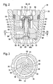
- Figure 2 shows a check valve of the high pressure pump in an enlarged view in a longitudinal section
- Figure 3 shows the check valve in a cross section along line III-III in Figure 2
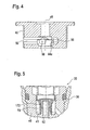
- Figure 4 shows the check valve according to a modified embodiment in a section along line IV-IV in Figure 3
- Figure 5 shows a detail of the check valve according to another modified embodiment.
- FIG. 1 shows a high-pressure pump 10 for a fuel injection device of an internal combustion engine, which is preferably a self-igniting internal combustion engine.
- the high pressure pump 10 fuel is conveyed under high pressure in a memory 12, is taken from the fuel for injection to the internal combustion engine.
- the high-pressure pump 10 is supplied by a feed pump 14 fuel.
- the high-pressure pump 10 has at least one pump element 16 which has a pump piston 20 driven at least indirectly by a drive shaft 18 of the high-pressure pump 10 in a lifting movement.
- the pump piston 20 is tightly guided in a cylinder bore 22 extending at least approximately radially to the drive shaft 18 and delimits a pump working space 24 in the outer end region of the cylinder bore 22 facing away from the drive shaft 18.
- the drive shaft 18 has a cam or a shaft section 26 eccentric to its axis of rotation 19 , via which during the rotational movement of the drive shaft 18, the lifting movement of the pump piston 20 is effected.
- the pump working chamber 24 can be connected to the inlet pump 30, which opens into the pump working chamber 24 and is designed as a check valve, with a fuel feed from the feed pump 14.
- the pump working chamber 24 can also be connected to the accumulator 12 via a discharge valve 32, which opens out of the pump working chamber 24 and is designed as a check valve, with a fuel outlet.
- the pump piston 20 in the cylinder bore 22 moves radially inwards, so that the volume of the pump working chamber 24 is increased.
- the inlet valve 30 When suction stroke of the pump piston 20, the inlet valve 30 is opened because of the existing pressure difference, as of the feed pump 14, a higher pressure is generated than the pressure prevailing in the pump working chamber 24, so that funded by the feed pump 14 fuel is sucked into the pump working chamber 24.
- the outlet valve 32nd is closed during the suction stroke of the pump piston 20, as in the memory 12, a higher pressure than in the pump working chamber 24 prevails.
- the inlet valve 30 is inserted into a bore 34 of a housing part 36 of the high-pressure pump 10 which adjoins the cylinder bore 22 radially outward.
- the bore 34 is formed larger in diameter relative to the cylinder bore 22.
- the housing part 36 may for example be a cylinder head which is connected to another housing part in which the drive shaft 18 is mounted, or a housing part, in which the drive shaft 18 is mounted.
- In the bore 34 opens near the cylinder bore 22 facing end portion, for example, approximately radially to the axis of the bore 34, a fuel inlet channel 38 which is connected to the feed pump 14.
- the inlet valve 30 has an integral valve housing 40, which is cup-shaped.
- the valve housing 40 has a jacket region delimiting a recess 41 and a base 42 adjoining it.
- the valve housing 40 has with the open end of its recess 41 to the outside.
- the valve housing 40 has with its bottom 42 inwardly to the cylinder bore 22 and in the bottom 42 is a bore 44 with its longitudinal axis 45 at least approximately coaxial with the cylinder bore 22 is introduced.
- the bore 44 has a large diameter portion 44a toward the cylinder bore 22 and a smaller diameter portion 44b toward the recess 41 of the valve body 40.
- a valve seat 48 is formed, which is for example at least approximately conical.
- the valve housing 40 may be formed, for example, as a forged part into which the bore 44 is introduced after forging and the valve seat 48 is produced.
- inlet channel 50 In the bottom 40 of the valve housing 40 at least one at least approximately perpendicular to the longitudinal axis 45 of the bore 44 extending inlet channel 50 is introduced, which opens on the one hand on the outer surface of the bottom 42 and on the other hand in the bore portion 44a. Preferably, several, for example, three over the circumference of the valve housing 40 evenly distributed feed channels 50 are provided.
- the inlet channels 50 open into the bore section 44a such that their longitudinal axes 51 do not intersect with the longitudinal axis 45 of the bore section 44a and the inlet channels 50 open at least approximately tangentially into the bore section 44a, as shown in FIG.
- the valve housing 40 has a somewhat reduced diameter in the region of the bottom 42, so that an annular space 52 is formed between the outer casing of the bottom 42 and the bore 34. In the annular space 52 open the inlet channel 38 and the inlet channels 50 in the bottom 42. In the shell of the valve housing 40 at least one bore 54 is introduced, which connects the recess 41 of the valve housing 40 with the annular space 52.
- the inlet channels 50 may be formed as bores, as shown in Figures 2 and 3. Alternatively, the inlet channels 50 may also have a non-circular cross-section as shown in FIG. In this case, the inlet channels 50 can be designed in particular such that their width in the direction of the longitudinal axis 45 of the bore 44 is greater than perpendicular to the longitudinal axis 45, as shown in FIG.
- the feed channels 50 can be made with this cross-sectional shape, for example, by starting from a bore by eroding the non-circular cross-section is produced.
- the end region of the inlet channels 50 is preferably rounded as shown in Figure 4 in the junction 44 in the bore.
- the above-described embodiment of at least one inlet channel 50 is independent of the one-piece design of the valve housing 40 and can also be used in any other, even multi-part designs of the valve housing 40.
- the inlet valve 30 has a piston-shaped valve member 60, which is guided displaceably with a shaft 62 in the bore section 44b and protrudes with the end region of the shaft 62 out of the bore section 44b into the recess 41 of the valve housing 40. From the bottom 42 can protrude into the recess 41 projecting lug 43 to ensure a large length of the bore portion 44b and thus a good guidance of the shaft 62 of the valve member 60.
- the valve member 60 At its end region facing away from the shaft 62, the valve member 60 has a closing body 64 which is larger in diameter than the shaft 62. In a region 66 arranged between the closing body 64 and the shaft 62, which is arranged in the bore section 44a, the valve member 60 has a constriction.
- the constricted region 66 of the valve member 60 is preferably rounded.
- a sealing surface 68 is formed at the transition to the constricted region 66, which may be formed, for example, conical.
- a closing spring 70 is arranged, which is supported on the one hand on the inside of the bottom 42 and on the other hand via a spring plate 72 on the valve member 60.
- a spring plate 72 is introduced, for example, into which a resilient locking ring 76 is engaged, through which the spring plate 72 is held.
- the valve housing 40 is preferably screwed into the bore 34 of the housing part 36, wherein the valve housing 40 has an external thread and the bore 34 has an internal thread.
- a profile 80 is mounted in order to be able to attack with a corresponding tool to a rotation on the valve housing 40 can.
- a seal between the annular shoulder 33 formed at the transition from the cylinder bore 22 to the bore 34 and the facing end face of the bottom 42 of the valve housing 40 can be ensured by a sealing ring 82 arranged between the annular shoulder 33 and the bottom 42.
- the sealing disc may be made of plastic or soft metal, such as soft iron or copper.
- the sealing disc 82 can also be omitted, in which case a narrow, raised sealing edge is formed on the bottom 42 of the valve housing 40 or on the annular shoulder 33, which is elastically or plastically deformed when the valve housing 40 is screwed into the bore 34 and ensures the sealing.
- the annular shoulder 33 and the end face of the bottom 42 may also be provided with flat sealing surfaces which are pressed against each other when screwing the valve housing 40 into the bore 34. A seal of the bore 34 to the outside by a between the outer shell of the valve housing 40 and the bore 34 near the outer end of the valve housing 40 clamped sealing ring 84th
- the valve member 60 is in its opening direction of the via the inlet bores 50, the bore portion 44 a fed, generated by the feed pump 14 pressure.
- the acted upon by the pressure in the opening direction surface of the valve member 60 at the transition to the closing body 64 is greater than the acted upon in the closing direction surface to the shaft 62 out, so that in the opening direction acting on the valve member 60 force is generated.
- a higher pressure generated by the feed pump 14 prevails in the fuel feed than in the pump working chamber 24, so that the valve member 60 opens against the force of the closing spring 70 and lifts off from the valve seat 48 with its sealing surface 68 and thereby an annular flow cross-section into the pump working space 24 releases.
- the inflow of the fuel from the inlet bores 50 into the bore portion 44a takes place as a result of the tangential mouth of the inlet bores 50 in the bore portion 44a with low flow losses. Due to the tangential mouth of the inlet bores 50, the incoming fuel receives a twist. The outlet of the inlet bores 50 in the bore section 44a can be rounded. Due to the rounded configuration of the constricted region 66 of the valve member 60, there is further an outflow of the fuel from the bore section 44a through the annular gap between the sealing surface 68 of the valve member 60 and the valve seat 48 into the pump working space 24. Thus, a good filling of the pump working chamber 24 is made possible.
- a possible wear of the sealing surface 68 of the valve member 60 and the valve seat 48 on the valve housing 40 does not lead to a change in the pressurized surfaces of the valve member 60 and thus not to a change in the opening differential pressure of the inlet valve 30.
- the recess 41 of the valve housing 40 is above the bore 54th connected to the annular space 52, so that during the opening stroke of the valve member 60 of this from the recess 41 displaced fuel can flow into the annular space 52 and the closing stroke of the annular space 52 fuel in the Recess 41 can flow.
- a rapid closing of the inlet valve 30 is achieved and a pressure increase in the recess 41 and thereby caused a burden of the lid 78 is avoided.
- the inlet valve 30 is shown in fragmentary form according to a modified embodiment of Figure 2 embodiment.
- the basic structure of the inlet valve is unchanged, it is only the training and attachment of the spring plate 172 on the shaft 62 of the valve member 60 modified.
- the spring plate 172 is sleeve-shaped and, for example, pressed onto the shaft 62 of the valve member 60.
- annular groove 74 and the locking ring 76 can be omitted, so that the structure of the inlet valve 30 is simplified accordingly.
Landscapes
- Engineering & Computer Science (AREA)
- General Engineering & Computer Science (AREA)
- Mechanical Engineering (AREA)
- Chemical & Material Sciences (AREA)
- Combustion & Propulsion (AREA)
- Fuel-Injection Apparatus (AREA)
Abstract
Description
- Die Erfindung geht aus von einem Rückschlagventil nach der Gattung des Anspruchs 1.
- Ein solches Rückschlagventil ist durch die
AU417351 B2 - Das erfindungsgemäße Rückschlagventil mit den Merkmalen gemäß Anspruch 1 hat demgegenüber den Vorteil, dass bei diesem eine Einströmung zumindest annähernd senkrecht zur Längsachse des Ventilglieds ermöglicht ist, wobei eine Abdichtung der Ausnehmung zur Außenseite der Aufnahme sichergestellt ist.
- Die Ausbildung gemäß Anspruch 2 ermöglicht eine einfache Abstützung der Schliessfeder.
- Ein Ausführungsbeispiel der Erfindung ist in der Zeichnung dargestellt und in der nachfolgenden Beschreibung näher erläutert. Es zeigen Figur 1 eine Hochdruckpumpe für eine Kraftstoffeinspritzeinrichtung einer Brennkraftmaschine, Figur 2 ein Rückschlagventil der Hochdruckpumpe in vergrößerter Darstellung in einem Längsschnitt, Figur 3 das Rückschlagventil in einem Querschnitt entlang Linie III-III in Figur 2, Figur 4 das Rückschlagventil gemäß einer modifizierten Ausführung in einem Schnitt entlang Linie IV-IV in Figur 3 und Figur 5 ausschnittsweise das Rückschlagventil gemäß einer weiteren modifizierten Ausführung.
- In Figur 1 ist eine Hochdruckpumpe 10 für eine Kraftstoffeinspritzeinrichtung einer Brennkraftmaschine dargestellt, die vorzugsweise eine selbstzündende Brennkraftmaschine ist. Durch die Hochdruckpumpe 10 wird Kraftstoff unter Hochdruck in einen Speicher 12 gefördert, aus dem Kraftstoff zur Einspritzung an der Brennkraftmaschine entnommen wird. Der Hochdruckpumpe 10 wird durch eine Förderpumpe 14 Kraftstoff zugeführt. Die Hochdruckpumpe 10 weist wenigstens ein Pumpenelement 16 auf, das einen zumindest mittelbar durch eine Antriebswelle 18 der Hochdruckpumpe 10 in einer Hubbewegung angetriebenen Pumpenkolben 20 aufweist. Der Pumpenkolben 20 ist in einer zumindest annähernd radial zur Antriebswelle 18 verlaufenden Zylinderbohrung 22 dicht geführt und begrenzt in dem der Antriebswelle 18 abgewandten äusseren Endbereich der Zylinderbohrung 22 einen Pumpenarbeitsraum 24. Die Antriebswelle 18 weist einen Nocken oder einen zu ihrer Drehachse 19 exzentrischen Wellenabschnitt 26 auf, über den bei der Drehbewegung der Antriebswelle 18 die Hubbewegung des Pumpenkolbens 20 bewirkt wird. Der Pumpenarbeitsraum 24 ist über ein in den Pumpenarbeitsraum 24 öffnendes, als Rückschlagventil ausgebildetes Einlassventil 30 mit einem Kraftstoffzulauf von der Förderpumpe 14 her verbindbar. Der Pumpenarbeitsraum 24 ist außerdem über eine aus dem Pumpenarbeitsraum 24 öffnendes, als Rückschlagventil ausgebildetes Auslassventil 32 mit einem Kraftstoffablauf zum Speicher 12 hin verbindbar. Beim Saughub bewegt sich der Pumpenkolben 20 in der Zylinderbohrung 22 radial nach innen, so dass das Volumen des Pumpenarbeitsraums 24 vergrößert wird. Beim Saughub des Pumpenkolbens 20 ist wegen der dabei bestehenden Druckdifferenz das Einlassventil 30 geöffnet, da von der Förderpumpe 14 ein höherer Druck erzeugt wird als der im Pumpenarbeitsraum 24 herrschende Druck, so dass von der Förderpumpe 14 geförderter Kraftstoff in den Pumpenarbeitsraum 24 angesaugt wird. Das Auslassventil 32 ist beim Saughub des Pumpenkolbens 20 geschlossen, da im Speicher 12 ein höherer Druck als im Pumpenarbeitsraum 24 herrscht.
- Nachfolgend wird das Einlassventil 30 anhand der Figuren 2 bis 4 näher beschrieben. Das Einlassventil 30 ist in eine sich radial nach aussen an die Zylinderbohrung 22 anschliessende Bohrung 34 eines Gehäuseteils 36 der Hochdruckpumpe 10 eingesetzt. Die Bohrung 34 ist dabei im Durchmesser gegenüber der Zylinderbohrung 22 größer ausgebildet. Das Gehäuseteil 36 kann beispielsweise ein Zylinderkopf sein, der mit einem andere Gehäuseteil, in dem die Antriebswelle 18 gelagert ist, verbunden ist oder ein Gehäuseteil sein, in dem auch die Antriebswelle 18 gelagert ist. In die Bohrung 34 mündet nahe deren der Zylinderbohrung 22 zugewandtem Endbereich beispielsweise etwa radial zur Achse der Bohrung 34 ein Kraftstoffzulaufkanal 38, der mit der Förderpumpe 14 verbunden ist. Das Einlassventil 30 weist ein einstückiges Ventilgehäuse 40 auf, das topfförmig ausgebildet ist. Das Ventilgehäuse 40 weist dabei einen eine Ausnehmung 41 begrenzenden Mantelbereich und einen an diesen anschliessenden Boden 42 auf. Das Ventilgehäuse 40 weist mit dem offenen Ende seiner Ausnehmung 41 nach aussen. Das Ventilgehäuse 40 weist mit seinem Boden 42 nach innen zur Zylinderbohrung 22 und im Boden 42 ist eine Bohrung 44 mit ihrer Längsachse 45 zumindest annähernd koaxial zur Zylinderbohrung 22 eingebracht. Die Bohrung 44 weist zur Zylinderbohrung 22 hin einen Abschnitt 44a mit großem Durchmesser und zur Ausnehmung 41 des Ventilgehäuses 40 hin einen Abschnitt 44b mit kleinerem Durchmesser auf. An der Mündung des Bohrungsabschnitts 44a zur Zylinderbohrung 22 hin ist ein Ventilsitz 48 ausgebildet, der beispielsweise zumindest annähernd kegelförmig ausgebildet ist. Das Ventilgehäuse 40 kann beispielsweise als Schmiedeteil ausgebildet sein, in das nach dem Schmieden die Bohrung 44 eingebracht und der Ventilsitz 48 hergestellt wird.
- Im Boden 40 des Ventilgehäuses 40 ist wenigstens ein zumindest annähernd senkrecht zur Längsachse 45 der Bohrung 44 verlaufender Zulaufkanal 50 eingebracht, der einerseits am Aussenmantel des Bodens 42 und andererseits im Bohrungsabschnitt 44a mündet. Vorzugsweise sind mehrere, beispielsweise drei über den Umfang des Ventilgehäuses 40 gleichmäßig verteilte Zulaufkanäle 50 vorgesehen. Die Zulaufkanäle 50 münden dabei in den Bohrungsabschnitt 44a derart, dass sich ihre Längsachsen 51 mit der Längsachse 45 des Bohrungsabschnitts 44a nicht schneiden und die Zulaufkanäle 50 zumindest annähernd tangential in den Bohrungsabschnitt 44a münden, wie dies in Figur 3 dargestellt ist. Das Ventilgehäuse 40 weist im Bereich des Bodens 42 einen etwas verringerten Durchmesser auf, so dass zwischen dem Aussenmantel des Bodens 42 und der Bohrung 34 ein Ringraum 52 gebildet ist. In den Ringraum 52 münden der Zulaufkanal 38 und die Zulaufkanäle 50 im Boden 42. Im Mantel des Ventilgehäuses 40 ist wenigstens eine Bohrung 54 eingebracht, die die Ausnehmung 41 des Ventilgehäuses 40 mit dem Ringraum 52 verbindet.
- Die Zulaufkanäle 50 können als Bohrungen ausgebildet sein, wie dies in den Figuren 2 und 3 dargestellt ist. Alternativ können die Zulaufkanäle 50 auch wie in Figur 4 dargestellt einen nichtkreisförmigen Querschnitt aufweisen. Dabei können die Zulaufkanäle 50 insbesondere so ausgebildet sein, dass deren Breite in Richtung der Längsachse 45 der Bohrung 44 größer ist als senkrecht zur Längsache 45, wie dies in Figur 4 dargestellt ist. Die Zulaufkanäle 50 können mit dieser Querschnittsform beispielsweise hergestellt werden, indem ausgehend von einer Bohrung durch Erodieren der nichtkreisförmige Querschnitt hergestellt wird. Der Endbereich der Zulaufkanäle 50 ist vorzugsweise wie in Figur 4 dargestellt in der Einmündung in die Bohrung 44 gerundet ausgebildet. Die vorstehend beschriebene Ausbildung des wenigstens einen Zulaufkanals 50 ist unabhängig von der einstückigen Ausbildung des Ventilgehäuses 40 und kann auch bei beliebigen anderen, auch mehrteiligen Ausführungen des Ventilgehäuses 40 verwendet werden.
- Das Einlassventil 30 weist ein kolbenförmiges Ventilglied 60 auf, das mit einem Schaft 62 im Bohrungsabschnitt 44b verschiebbar geführt ist und mit dem Endbereich des Schafts 62 aus dem Bohrungsabschnitt 44b heraus in die Ausnehmung 41 des Ventilgehäuses 40 ragt. Vom Boden 42 kann dabei ein in die Ausnehmung 41 ragender Ansatz 43 abstehen, um eine große Länge des Bohrungsabschnitts 44b und damit eine gute Führung des Schafts 62 des Ventilglieds 60 sicherzustellen. An seinem dem Schaft 62 abgewandten Endbereich weist das Ventilglied 60 einen im Durchmesser gegenüber dem Schaft 62 größeren Schließkörper 64 auf. In einem zwischen dem Schließkörper 64 und dem Schaft 62 angeordneten Bereich 66, der im Bohrungsabschnitt 44a angeordnet ist, weist das Ventilglied 60 eine Einschnürung auf. Der eingeschnürte Bereich 66 des Ventilglieds 60 ist vorzugsweise gerundet ausgebildet. Am Schließkörper 64 ist am Übergang zum eingeschnürten Bereich 66 eine Dichtfläche 68 ausgebildet, die beispielsweise kegelförmig ausgebildet sein kann.
- In der Ausnehmung 41 des Ventilgehäuses 40 ist eine Schliessfeder 70 angeordnet, die sich einerseits an der Innenseite des Bodens 42 und andererseits über einen Federteller 72 am Ventilglied 60 abstützt. Am in der Ausnehmung 41 des Ventilgehäuses 40 angeordneten Endbereich des Schafts 62 des Ventilglieds 60 ist dabei beispielsweise eine Ringnut 74 eingebracht, in die ein federnder Sicherungsring 76 eingerastet ist, durch den der Federteller 72 gehalten wird. Durch die vorgespannte Schliessfeder 70 wird das Ventilglied 60 in seiner Schliessrichtung beaufschlagt, in der es mit seiner Dichtfläche 68 am Ventilsitz 48 zur Anlage kommt. Das offene Ende der Ausnehmung 41 des Ventilgehäuses 40 ist mit einem Deckel 78 verschlossen, der beispielsweise in die Ausnehmung 41 eingepresst ist.
- Das Ventilgehäuse 40 ist vorzugsweise in die Bohrung 34 des Gehäuseteils 36 eingeschraubt, wobei das Ventilgehäuse 40 ein Aussengewinde und die Bohrung 34 ein Innengewinde aufweist. Am äusseren Randbereich der Ausnehmung 41 ist ein Profil 80 angebracht, um mit einem entsprechenden Werkzeug zu einer Verdrehung am Ventilgehäuse 40 angreifen zu können. Eine Abdichtung zwischen der am Übergang von der Zylinderbohrung 22 zur Bohrung 34 gebildeten Ringschulter 33 und der dieser zugewandten Stirnseite des Bodens 42 des Ventilgehäuses 40 kann durch eine zwischen Ringschulter 33 und Boden 42 angeordnete Dichtscheibe 82 sichergestellt werden. Beim Einschrauben des Ventilgehäuses 40 in die Bohrung 34 wird die Dichtscheibe 82 elastisch oder plastisch verformt und stellt dadurch die Abdichtung sicher. Die Dichtscheibe kann aus Kunststoff oder aus weichem Metall, beispielsweise Weicheisen oder Kupfer bestehen. Alternativ kann die Dichtscheibe 82 auch entfallen, wobei dann am Boden 42 des Ventilgehäuses 40 oder an der Ringschulter 33 eine schmale erhabene Dichtkante ausgebildet ist, die beim Einschrauben des Ventilgehäuses 40 in die Bohrung 34 elastisch oder plastisch verformt wird und die Abdichtung sicherstellt. Weiterhin alternativ können die Ringschulter 33 und die Stirnseite des Bodens 42 auch mit ebenen Dichtflächen versehen sein, die beim Einschrauben des Ventilgehäuses 40 in die Bohrung 34 aufeinander gepresst werden. Eine Abdichtung der Bohrung 34 nach aussen erfolgt durch einen zwischen dem Aussenmantel des Ventilgehäuses 40 und der Bohrung 34 nahe dem äusseren Ende des Ventilgehäuses 40 eingespannten Dichtring 84.
- Das Ventilglied 60 ist in seiner Öffnungsrichtung von dem über die Zulaufbohrungen 50 dem Bohrungsabschnitt 44a zugeführten, durch die Förderpumpe 14 erzeugten Druck beaufschlagt. Die vom Druck in Öffnungsrichtung beaufschlagte Fläche des Ventilglieds 60 am Übergang zum Schließkörper 64 ist dabei größer als die in Schließrichtung beaufschlagte Fläche zum Schaft 62 hin, so dass eine in Öffnungsrichtung auf das Ventilglied 60 wirkende Kraft erzeugt wird. Beim Saughub des Pumpenkolbens 20 herrscht im Kraftstoffzulauf ein durch die Förderpumpe 14 erzeugter höherer Druck als im Pumpenarbeitsraum 24, so dass das Ventilglied 60 gegen die Kraft der Schliessfeder 70 öffnet und mit seiner Dichtfläche 68 vom Ventilsitz 48 abhebt und dadurch einen ringförmigen Durchflussquerschnitt in den Pumpenarbeitsraum 24 freigibt. Das Einströmen des Kraftstoffs von den Zulaufbohrungen 50 in den Bohrungsabschnitt 44a erfolgt dabei infolge der tangentialen Mündung der Zulaufbohrungen 50 in den Bohrungsabschnitt 44a mit geringen Strömungsverlusten. Durch die tangentiale Mündung der Zulaufbohrungen 50 erhält der einströmende Kraftstoff einen Drall. Der Auslauf der Zulaufbohrungen 50 im Bohrungsabschnitt 44a kann dabei gerundet sein. Durch die gerundete Ausbildung des eingeschnürten Bereichs 66 des Ventilglieds 60 erfolgt weiter eine Ausströmung des Kraftstoffs aus dem Bohrungsabschnitt 44a durch den Ringspalt zwischen der Dichtfläche 68 des Ventilglieds 60 und dem Ventilsitz 48 in den Pumpenarbeitsraum 24. Somit wird eine gute Befüllung des Pumpenarbeitsraums 24 ermöglicht. Ein eventueller Verschleiss der Dichtfläche 68 des Ventilglieds 60 und des Ventilsitzes 48 am Ventilgehäuse 40 führt nicht zu einer Änderung der druckbeaufschlagten Flächen des Ventilglieds 60 und damit nicht zu einer Änderung des Öffnungsdifferenzdruckes des Einlassventils 30. Die Ausnehmung 41 des Ventilgehäuses 40 ist über die Bohrung 54 mit dem Ringraum 52 verbunden, so dass beim Öffnungshub des Ventilgliedes 60 von diesem aus der Ausnehmung 41 verdrängter Kraftstoff in den Ringraum 52 strömen kann und beim Schließhub aus dem Ringraum 52 Kraftstoff in die Ausnehmung 41 einströmen kann. Hierdurch wird ein schnelles Schließen des Einlassventils 30 erreicht und ein Druckanstieg in der Ausnehmung 41 und eine hierdurch bewirkte Belastung des Deckels 78 vermieden.
- In Figur 5 ist das Einlassventil 30 ausschnittsweise gemäß einer gegenüber der Ausführung in Figur 2 modifizierten Ausführung dargestellt. Der grundsätzliche Aufbau des Einlassventils ist dabei unverändert, es ist lediglich die Ausbildung und Befestigung des Federtellers 172 auf dem Schaft 62 des Ventilglieds 60 modifiziert. Der Federteller 172 ist hülsenförmig ausgebildet und beispielsweise auf den Schaft 62 des Ventilglieds 60 aufgepresst. Bei dieser Ausbildung können somit die bei der Ausführung gemäß Figur 2 vorgesehene Ringnut 74 und der Sicherungsring 76 entfallen, so dass der Aufbau des Einlassventils 30 entsprechend vereinfacht ist.
Claims (2)
- Rückschlagventil, insbesondere für eine Hochdruckpumpe einer Kraftstoffeinspritzeinrichtung für eine Brennkraftmaschine, mit einem in eine Aufnahme (34) eingesetzten Ventilgehäuse (40), in dem ein kolbenförmiges Ventilglied (60) längsverschiebbar geführt ist, das mit einem am Ventilgehäuse (40) ausgebildeten Ventilsitz (48) zusammenwirkt, wobei das Ventilglied (60) in Schliessrichtung durch eine vorgespannte Schliessfeder (70) und in Öffnungsrichtung durch den in einem Zulauf (44a) herrschenden Druck beaufschlagt ist, wobei das Ventilglied (60) von der Seite des Ventilsitzes (48) her in das Ventilgehäuse (40) eingesetzt ist, wobei das Ventilgehäuse (40) einstückig und topfförmig ausgebildet ist, wobei das Ventilgehäuse (40) einen Boden (42) sowie einen eine Ausnehmung (41) begrenzenden Mantelbereich aufweist, wobei das Ventilgehäuse (41) mit dem offenen Ende seiner Ausnehmung (41) aus der Aufnahme (34) weist, wobei der Ventilsitz (48) am Boden (42) des Ventilgehäuses (40) der Ausnehmung (41) abgewandt angeordnet ist, wobei das Ventilglied (60) mit einem Schaft (62) durch eine Bohrung (44b) im Boden (42) hindurch in die Ausnehmung (41) ragt, in der die Schliessfeder (70) angeordnet ist, und wobei die Ausnehmung (41) des Ventilgehäuses (40) mit einem Zulaufbereich (52) des Rückschlagventils (30) verbunden ist, dadurch gekennzeichnet, dass im Ventilgehäuse (40) wenigstens ein zumindest annähernd senkrecht zur Längsachse (45) des Ventilglieds (40) verlaufender Zulaufkanal (50) eingebracht ist, über den die Einströmung in das Rückschlagventil (30) erfolgt, und dass die Ausnehmung (41) des Ventilgehäuses (40) an ihrem dem Boden (42) abgewandten Ende mit einem Deckel (78) verschlossen ist.
- Rückschlagventil nach Anspruch 1, dadurch gekennzeichnet, dass die Schliessfeder (70) sich einerseits an der in die Ausnehmung (41) weisenden Innenseite des Bodesn (42) und andererseits an einem mit dem Schaft (62) des Ventilglieds (60) verbundenen Federteller (72) abstützt.
Priority Applications (1)
| Application Number | Priority Date | Filing Date | Title |
|---|---|---|---|
| EP06117087A EP1736662B1 (de) | 2003-05-22 | 2004-04-08 | Rückschlagventil, insbesondere für eine Hochdruckpumpe einer Kraftstoffeinspritzeinrichtung für eine Brennkraftmaschine |
Applications Claiming Priority (3)
| Application Number | Priority Date | Filing Date | Title |
|---|---|---|---|
| DE10323147 | 2003-05-22 | ||
| DE10346211A DE10346211A1 (de) | 2003-05-22 | 2003-10-06 | Rückschlagventil, insbesondere für eine Hochdruckpumpe einer Kraftstoffeinspritzeinrichtung für eine Brennkraftmaschine |
| PCT/DE2004/000741 WO2004109093A1 (de) | 2003-05-22 | 2004-04-08 | Rückschlagventil, insbesondere für eine hochdruckpumpe einer kraftstoffeinspritzeinrichtung für eine brennkraftmaschine |
Related Child Applications (1)
| Application Number | Title | Priority Date | Filing Date |
|---|---|---|---|
| EP06117087A Division EP1736662B1 (de) | 2003-05-22 | 2004-04-08 | Rückschlagventil, insbesondere für eine Hochdruckpumpe einer Kraftstoffeinspritzeinrichtung für eine Brennkraftmaschine |
Publications (2)
| Publication Number | Publication Date |
|---|---|
| EP1636488A1 EP1636488A1 (de) | 2006-03-22 |
| EP1636488B1 true EP1636488B1 (de) | 2008-01-23 |
Family
ID=33512378
Family Applications (1)
| Application Number | Title | Priority Date | Filing Date |
|---|---|---|---|
| EP20040726424 Expired - Lifetime EP1636488B1 (de) | 2003-05-22 | 2004-04-08 | Rückschlagventil, insbesondere für eine hochdruckpumpe einer kraftstoffeinspritzeinrichtung für eine brennkraftmaschine |
Country Status (5)
| Country | Link |
|---|---|
| US (1) | US7290559B2 (de) |
| EP (1) | EP1636488B1 (de) |
| JP (1) | JP2006513367A (de) |
| DE (2) | DE502004007338D1 (de) |
| WO (1) | WO2004109093A1 (de) |
Families Citing this family (17)
| Publication number | Priority date | Publication date | Assignee | Title |
|---|---|---|---|---|
| DE10357612A1 (de) * | 2003-12-10 | 2005-07-07 | Robert Bosch Gmbh | Ventilanordnung, insbesondere Einlassventil einer Hochdruck-Kraftstoffpumpe |
| DE102004027825A1 (de) * | 2004-02-11 | 2005-09-01 | Robert Bosch Gmbh | Hochdruckpumpe, insbesondere für eine Kraftstoffeinspritzeinrichtung einer Brennkraftmaschine |
| DE102004007662B4 (de) * | 2004-02-17 | 2011-02-10 | Continental Automotive Gmbh | Druckregelventil für eine hydraulische Einrichtung und Verwendung des Druckregelventils |
| JP4415929B2 (ja) * | 2005-11-16 | 2010-02-17 | 株式会社日立製作所 | 高圧燃料供給ポンプ |
| DE102007017122A1 (de) * | 2007-04-11 | 2008-12-18 | Continental Automotive Gmbh | Ventil und Pumpe mit einem solchen Ventil |
| US7451741B1 (en) * | 2007-10-31 | 2008-11-18 | Caterpillar Inc. | High-pressure pump |
| US7891374B2 (en) * | 2009-05-12 | 2011-02-22 | Vicars Berton L | Suction valve |
| EP2278163A1 (de) * | 2009-07-20 | 2011-01-26 | Delphi Technologies Holding S.à.r.l. | Pumpenanordnung |
| DE102010013106A1 (de) * | 2010-03-26 | 2011-09-29 | Thomas Magnete Gmbh | Pumpe |
| ITBO20110600A1 (it) | 2011-10-21 | 2013-04-22 | S T S R L | Apparato e metodo di taratura di una valvola |
| ITBO20110599A1 (it) | 2011-10-21 | 2013-04-22 | S T S R L | Valvola oleo-idraulica |
| DE102013204327A1 (de) * | 2013-03-13 | 2014-09-18 | Robert Bosch Gmbh | Zylinderkopfrohteil, Zylinderkopf und Hochdruckpumpe für Brennstoffeinspritzanlagen |
| AT516621B1 (de) * | 2015-02-27 | 2016-07-15 | Ge Jenbacher Gmbh & Co Og | Vorkammergasventil |
| ITUA20161816A1 (it) * | 2016-03-18 | 2017-09-18 | Bosch Gmbh Robert | Gruppo di pompaggio per alimentare combustibile, preferibilmente gasolio, ad un motore a combustione interna |
| GB2570327B (en) * | 2018-01-22 | 2020-06-24 | Perkins Engines Co Ltd | Cylinder head for engines |
| CN109084058B (zh) * | 2018-11-01 | 2023-09-05 | 安徽省屯溪高压阀门股份有限公司 | 一种自泄压式止回阀 |
| DE102019119302A1 (de) * | 2019-07-16 | 2021-01-21 | Norma Germany Gmbh | Ablaufstutzen zum getrennten Auslassen von Flüssigkeiten unterschiedlicher Dichte |
Family Cites Families (16)
| Publication number | Priority date | Publication date | Assignee | Title |
|---|---|---|---|---|
| US620936A (en) * | 1899-03-14 | kunzer | ||
| US653860A (en) * | 1900-01-15 | 1900-07-17 | Milton Bulkley | Puppet-valve for air-compressors. |
| US688392A (en) * | 1901-08-03 | 1901-12-10 | Rand Drill Company | Valve for compressors. |
| US1050048A (en) * | 1910-05-16 | 1913-01-07 | Cleveland Ice Machine & Mfg Company | Compressor-valve. |
| US1105134A (en) * | 1913-11-12 | 1914-07-28 | Engelbert Hanemann | Carbureter. |
| US1229571A (en) * | 1916-08-28 | 1917-06-12 | Los Angeles Motor Car Company | Valve. |
| US1554683A (en) * | 1924-09-24 | 1925-09-22 | Jr Marcus W Mount | Air take-off device |
| AU417351B2 (en) | 1967-05-24 | 1971-09-17 | Joseph Lucas (Industries) Limited | Pressure operable valves |
| US4084609A (en) * | 1976-09-17 | 1978-04-18 | Caterpillar Tractor Co. | Cartridge type check valve |
| DE10247839A1 (de) | 2002-10-14 | 2004-04-22 | Stein, Günter | Rückschlagventil für strömbare Medien |
| US5172720A (en) * | 1992-02-03 | 1992-12-22 | Eaton Corporation | Single seal fluid control valve |
| DE19729791A1 (de) * | 1997-07-11 | 1999-01-14 | Bosch Gmbh Robert | Radialkolbenpumpe zur Kraftstoffhochdruckversorgung |
| DE19744577A1 (de) * | 1997-10-09 | 1999-04-22 | Bosch Gmbh Robert | Radialkolbenpumpe zur Kraftstoffhochdruckversorgung |
| DE19834121A1 (de) * | 1998-07-29 | 2000-02-03 | Bosch Gmbh Robert | Kraftstoffversorgungsanlage einer Brennkraftmaschine |
| IT1310755B1 (it) * | 1999-11-30 | 2002-02-22 | Elasis Sistema Ricerca Fiat | Pompa idraulica ad alta pressione, in particolare pompa a pistoniradiali per il carburante di un motore a combustione interna. |
| JP2003161227A (ja) * | 2001-11-29 | 2003-06-06 | Denso Corp | 燃料噴射ポンプおよびその逆止弁装置の組み付け方法 |
-
2004
- 2004-04-08 DE DE200450007338 patent/DE502004007338D1/de not_active Expired - Lifetime
- 2004-04-08 US US10/537,544 patent/US7290559B2/en not_active Expired - Fee Related
- 2004-04-08 DE DE200450006054 patent/DE502004006054D1/de not_active Expired - Lifetime
- 2004-04-08 JP JP2005518343A patent/JP2006513367A/ja active Pending
- 2004-04-08 EP EP20040726424 patent/EP1636488B1/de not_active Expired - Lifetime
- 2004-04-08 WO PCT/DE2004/000741 patent/WO2004109093A1/de not_active Ceased
Also Published As
| Publication number | Publication date |
|---|---|
| JP2006513367A (ja) | 2006-04-20 |
| US20060039811A1 (en) | 2006-02-23 |
| US7290559B2 (en) | 2007-11-06 |
| DE502004006054D1 (de) | 2008-03-13 |
| EP1636488A1 (de) | 2006-03-22 |
| WO2004109093A1 (de) | 2004-12-16 |
| DE502004007338D1 (de) | 2008-07-17 |
Similar Documents
| Publication | Publication Date | Title |
|---|---|---|
| EP1727983B1 (de) | Hochdruckpumpe, insbesondere für eine kraftstoffeinspritzeinrichtung einer brennkraftmaschine | |
| EP1931875B1 (de) | Hochdruckpumpe, insbesondere für eine kraftstoffeinspritzeinrichtung einer brennkraftmaschine | |
| EP2032850B1 (de) | Hochdruckpumpe, insbesondere für eine kraftstoffeinspritzeinrichtung einer brennkraftmaschine | |
| EP1697631B1 (de) | Ventil, insbesondere für eine hochdruckpumpe einer kraftstof feinspritzeinrichtung für eine brennkraftmaschine | |
| EP1989436B1 (de) | Kraftstoffeinspritzvorrichtung für eine brennkraftmaschine | |
| WO2004109093A1 (de) | Rückschlagventil, insbesondere für eine hochdruckpumpe einer kraftstoffeinspritzeinrichtung für eine brennkraftmaschine | |
| EP1736662B1 (de) | Rückschlagventil, insbesondere für eine Hochdruckpumpe einer Kraftstoffeinspritzeinrichtung für eine Brennkraftmaschine | |
| EP1784571B1 (de) | Hochdruckpumpe für eine kraftstoffeinspritzeinrichtung einer brennkraftmaschine | |
| EP3061967B1 (de) | Pumpe, insbesondere kraftstoffhochdruckpumpe | |
| DE102004027825A1 (de) | Hochdruckpumpe, insbesondere für eine Kraftstoffeinspritzeinrichtung einer Brennkraftmaschine | |
| EP1716332A1 (de) | Hochdruckpumpe, insbesondere f ür eine kraftstoffeinspritzein richtung einer brennkraftmaschine | |
| EP2304220B1 (de) | Hochdruckpumpe | |
| DE102008001824A1 (de) | Pumpe, insbesondere Kraftstoffhochdruckpumpe, und Rückschlagventil, insbesondere für eine Pumpe | |
| EP1759115B1 (de) | Hochdruckpumpe für eine kraftstoffeinspritzeinrichtung einer brennkraftmaschine | |
| EP1281861B1 (de) | Kraftstoff-Einspritzeinrichtung für Brennkraftmaschinen | |
| EP3039282B1 (de) | Pumpe, insbesondere eine kraftstoffhochdruckpumpe | |
| EP1284360B1 (de) | Kraftstoffeinspritzeinrichtung für eine Brennkraftmaschine | |
| WO2013037544A1 (de) | Rückschlagventil, insbesondere für eine kraftstoffhochdruckpumpe, und pumpe mit rückschlagventil | |
| DE102005035671B4 (de) | Kraftstoffinjektor für eine Brennkraftmaschine | |
| DE102004040141A1 (de) | Kraftstoffeinspritzeinrichtung für eine Brennkraftmaschine | |
| DE102013204897A1 (de) | Pumpe, insbesondere Kraftstoffhochdruckpumpe für eine Kraftstoffeinspritzeinrichtung | |
| WO2015052083A1 (de) | Pumpe, insbesondere kraftstoffhochdruckpumpe | |
| DE102009002486A1 (de) | Kraftstoff-Hochdruckpumpe | |
| DE102011082733A1 (de) | Pumpe, insbesondere Kraftstoffhochdruckpumpe |
Legal Events
| Date | Code | Title | Description |
|---|---|---|---|
| PUAI | Public reference made under article 153(3) epc to a published international application that has entered the european phase |
Free format text: ORIGINAL CODE: 0009012 |
|
| 17P | Request for examination filed |
Effective date: 20051222 |
|
| AK | Designated contracting states |
Kind code of ref document: A1 Designated state(s): DE FR GB IT |
|
| DAX | Request for extension of the european patent (deleted) | ||
| RBV | Designated contracting states (corrected) |
Designated state(s): DE FR GB IT |
|
| 17Q | First examination report despatched |
Effective date: 20060320 |
|
| GRAP | Despatch of communication of intention to grant a patent |
Free format text: ORIGINAL CODE: EPIDOSNIGR1 |
|
| GRAS | Grant fee paid |
Free format text: ORIGINAL CODE: EPIDOSNIGR3 |
|
| GRAA | (expected) grant |
Free format text: ORIGINAL CODE: 0009210 |
|
| AK | Designated contracting states |
Kind code of ref document: B1 Designated state(s): DE FR GB IT |
|
| REG | Reference to a national code |
Ref country code: GB Ref legal event code: FG4D Free format text: NOT ENGLISH |
|
| REF | Corresponds to: |
Ref document number: 502004006054 Country of ref document: DE Date of ref document: 20080313 Kind code of ref document: P |
|
| GBT | Gb: translation of ep patent filed (gb section 77(6)(a)/1977) |
Effective date: 20080423 |
|
| ET | Fr: translation filed | ||
| PLBE | No opposition filed within time limit |
Free format text: ORIGINAL CODE: 0009261 |
|
| STAA | Information on the status of an ep patent application or granted ep patent |
Free format text: STATUS: NO OPPOSITION FILED WITHIN TIME LIMIT |
|
| 26N | No opposition filed |
Effective date: 20081024 |
|
| PGFP | Annual fee paid to national office [announced via postgrant information from national office to epo] |
Ref country code: GB Payment date: 20100324 Year of fee payment: 7 |
|
| PGFP | Annual fee paid to national office [announced via postgrant information from national office to epo] |
Ref country code: FR Payment date: 20100506 Year of fee payment: 7 |
|
| PGFP | Annual fee paid to national office [announced via postgrant information from national office to epo] |
Ref country code: IT Payment date: 20100426 Year of fee payment: 7 |
|
| GBPC | Gb: european patent ceased through non-payment of renewal fee |
Effective date: 20110408 |
|
| REG | Reference to a national code |
Ref country code: FR Ref legal event code: ST Effective date: 20111230 |
|
| PG25 | Lapsed in a contracting state [announced via postgrant information from national office to epo] |
Ref country code: FR Free format text: LAPSE BECAUSE OF NON-PAYMENT OF DUE FEES Effective date: 20110502 |
|
| PG25 | Lapsed in a contracting state [announced via postgrant information from national office to epo] |
Ref country code: IT Free format text: LAPSE BECAUSE OF NON-PAYMENT OF DUE FEES Effective date: 20110408 Ref country code: GB Free format text: LAPSE BECAUSE OF NON-PAYMENT OF DUE FEES Effective date: 20110408 |
|
| PGFP | Annual fee paid to national office [announced via postgrant information from national office to epo] |
Ref country code: DE Payment date: 20120626 Year of fee payment: 9 |
|
| PG25 | Lapsed in a contracting state [announced via postgrant information from national office to epo] |
Ref country code: DE Free format text: LAPSE BECAUSE OF NON-PAYMENT OF DUE FEES Effective date: 20131101 |
|
| REG | Reference to a national code |
Ref country code: DE Ref legal event code: R119 Ref document number: 502004006054 Country of ref document: DE Effective date: 20131101 |