EP1636460B1 - Bewegungswandler zur umwandlung einer linear- in eine drehbewegung und umgekehrt - Google Patents
Bewegungswandler zur umwandlung einer linear- in eine drehbewegung und umgekehrt Download PDFInfo
- Publication number
- EP1636460B1 EP1636460B1 EP04737433.5A EP04737433A EP1636460B1 EP 1636460 B1 EP1636460 B1 EP 1636460B1 EP 04737433 A EP04737433 A EP 04737433A EP 1636460 B1 EP1636460 B1 EP 1636460B1
- Authority
- EP
- European Patent Office
- Prior art keywords
- axis
- shaft
- journal
- rotation
- cam
- Prior art date
- Legal status (The legal status is an assumption and is not a legal conclusion. Google has not performed a legal analysis and makes no representation as to the accuracy of the status listed.)
- Expired - Lifetime
Links
Images

Classifications
-
- F—MECHANICAL ENGINEERING; LIGHTING; HEATING; WEAPONS; BLASTING
- F02—COMBUSTION ENGINES; HOT-GAS OR COMBUSTION-PRODUCT ENGINE PLANTS
- F02F—CYLINDERS, PISTONS OR CASINGS, FOR COMBUSTION ENGINES; ARRANGEMENTS OF SEALINGS IN COMBUSTION ENGINES
- F02F7/00—Casings, e.g. crankcases
- F02F7/0002—Cylinder arrangements
- F02F7/0019—Cylinders and crankshaft not in one plane (deaxation)
-
- F—MECHANICAL ENGINEERING; LIGHTING; HEATING; WEAPONS; BLASTING
- F01—MACHINES OR ENGINES IN GENERAL; ENGINE PLANTS IN GENERAL; STEAM ENGINES
- F01B—MACHINES OR ENGINES, IN GENERAL OR OF POSITIVE-DISPLACEMENT TYPE, e.g. STEAM ENGINES
- F01B9/00—Reciprocating-piston machines or engines characterised by connections between pistons and main shafts, not specific to groups F01B1/00 - F01B7/00
- F01B9/02—Reciprocating-piston machines or engines characterised by connections between pistons and main shafts, not specific to groups F01B1/00 - F01B7/00 with crankshaft
- F01B9/026—Rigid connections between piston and rod; Oscillating pistons
-
- F—MECHANICAL ENGINEERING; LIGHTING; HEATING; WEAPONS; BLASTING
- F01—MACHINES OR ENGINES IN GENERAL; ENGINE PLANTS IN GENERAL; STEAM ENGINES
- F01B—MACHINES OR ENGINES, IN GENERAL OR OF POSITIVE-DISPLACEMENT TYPE, e.g. STEAM ENGINES
- F01B9/00—Reciprocating-piston machines or engines characterised by connections between pistons and main shafts, not specific to groups F01B1/00 - F01B7/00
- F01B9/04—Reciprocating-piston machines or engines characterised by connections between pistons and main shafts, not specific to groups F01B1/00 - F01B7/00 with rotary main shaft other than crankshaft
- F01B9/06—Reciprocating-piston machines or engines characterised by connections between pistons and main shafts, not specific to groups F01B1/00 - F01B7/00 with rotary main shaft other than crankshaft the piston motion being transmitted by curved surfaces
-
- F—MECHANICAL ENGINEERING; LIGHTING; HEATING; WEAPONS; BLASTING
- F02—COMBUSTION ENGINES; HOT-GAS OR COMBUSTION-PRODUCT ENGINE PLANTS
- F02B—INTERNAL-COMBUSTION PISTON ENGINES; COMBUSTION ENGINES IN GENERAL
- F02B75/00—Other engines
- F02B75/32—Engines characterised by connections between pistons and main shafts and not specific to preceding main groups
-
- F—MECHANICAL ENGINEERING; LIGHTING; HEATING; WEAPONS; BLASTING
- F16—ENGINEERING ELEMENTS AND UNITS; GENERAL MEASURES FOR PRODUCING AND MAINTAINING EFFECTIVE FUNCTIONING OF MACHINES OR INSTALLATIONS; THERMAL INSULATION IN GENERAL
- F16H—GEARING
- F16H21/00—Gearings comprising primarily only links or levers, with or without slides
- F16H21/10—Gearings comprising primarily only links or levers, with or without slides all movement being in, or parallel to, a single plane
- F16H21/16—Gearings comprising primarily only links or levers, with or without slides all movement being in, or parallel to, a single plane for interconverting rotary motion and reciprocating motion
- F16H21/18—Crank gearings; Eccentric gearings
- F16H21/36—Crank gearings; Eccentric gearings without swinging connecting-rod, e.g. with epicyclic parallel motion, slot-and-crank motion
-
- B—PERFORMING OPERATIONS; TRANSPORTING
- B63—SHIPS OR OTHER WATERBORNE VESSELS; RELATED EQUIPMENT
- B63H—MARINE PROPULSION OR STEERING
- B63H25/00—Steering; Slowing-down otherwise than by use of propulsive elements; Dynamic anchoring, i.e. positioning vessels by means of main or auxiliary propulsive elements
- B63H25/06—Steering by rudders
- B63H25/08—Steering gear
- B63H25/14—Steering gear power assisted; power driven, i.e. using steering engine
- B63H25/26—Steering engines
-
- B—PERFORMING OPERATIONS; TRANSPORTING
- B63—SHIPS OR OTHER WATERBORNE VESSELS; RELATED EQUIPMENT
- B63H—MARINE PROPULSION OR STEERING
- B63H25/00—Steering; Slowing-down otherwise than by use of propulsive elements; Dynamic anchoring, i.e. positioning vessels by means of main or auxiliary propulsive elements
- B63H25/06—Steering by rudders
- B63H25/08—Steering gear
- B63H25/14—Steering gear power assisted; power driven, i.e. using steering engine
- B63H25/34—Transmitting of movement of engine to rudder, e.g. using quadrants, brakes
-
- F—MECHANICAL ENGINEERING; LIGHTING; HEATING; WEAPONS; BLASTING
- F16—ENGINEERING ELEMENTS AND UNITS; GENERAL MEASURES FOR PRODUCING AND MAINTAINING EFFECTIVE FUNCTIONING OF MACHINES OR INSTALLATIONS; THERMAL INSULATION IN GENERAL
- F16H—GEARING
- F16H21/00—Gearings comprising primarily only links or levers, with or without slides
- F16H21/10—Gearings comprising primarily only links or levers, with or without slides all movement being in, or parallel to, a single plane
- F16H21/16—Gearings comprising primarily only links or levers, with or without slides all movement being in, or parallel to, a single plane for interconverting rotary motion and reciprocating motion
- F16H21/18—Crank gearings; Eccentric gearings
- F16H21/22—Crank gearings; Eccentric gearings with one connecting-rod and one guided slide to each crank or eccentric
- F16H21/30—Crank gearings; Eccentric gearings with one connecting-rod and one guided slide to each crank or eccentric with members having rolling contact
-
- Y—GENERAL TAGGING OF NEW TECHNOLOGICAL DEVELOPMENTS; GENERAL TAGGING OF CROSS-SECTIONAL TECHNOLOGIES SPANNING OVER SEVERAL SECTIONS OF THE IPC; TECHNICAL SUBJECTS COVERED BY FORMER USPC CROSS-REFERENCE ART COLLECTIONS [XRACs] AND DIGESTS
- Y10—TECHNICAL SUBJECTS COVERED BY FORMER USPC
- Y10T—TECHNICAL SUBJECTS COVERED BY FORMER US CLASSIFICATION
- Y10T74/00—Machine element or mechanism
- Y10T74/18—Mechanical movements
- Y10T74/18056—Rotary to or from reciprocating or oscillating
- Y10T74/18296—Cam and slide
Definitions
- the invention relates to an apparatus for converting linear motion into rotary motion or vice versa, and, in particular, to an apparatus for converting linear motion into rotary motion in an internal combustion engine.
- crankshaft has one or more offset portions which are offset from the axis of rotation of the crankshaft, and the or each connecting rod is mounted for rotation about one of the offset portions.
- the connecting rods By means of the axes of rotation of the connecting rods being spaced from the axis of rotation of the crankshaft, pistons constrained within cylinders and mounted to free ends of the connecting rods move in reciprocating linear motion as the crankshaft rotates.
- this arrangement is also limited to a symmetric cycle in which the piston travels at the same average velocity in the power and compression strokes.
- the device disclosed in this document is restricted to the offset of the crankpin from the axis of the crankshaft being the same as the offset of the axis of the cylindrical portion from the axis of the crankpin which limits the geometry achievable for the cycle of the device.
- GB 1460986 discloses a mechanism for converting rotary motion into linear reciprocating movement.
- the present invention seeks to provide an internal combustion engine.
- an internal combustion engine comprising: a piston; and an apparatus for converting linear motion into rotary motion or vice versa, the apparatus comprising a shaft which is rotatable about a fixed axis and carrying a circular cam mounted eccentrically relative to that axis, the cam being rotatably mounted within a circular journal, an axis of rotation of the cam relative to the journal being spaced from a center of the journal, the journal being in turn rotatably mounted within a housing mounted for reciprocating motion along a second axis in a direction perpendicular to the axis of the shaft whereby reciprocating motion of the housing along the second axis is converted into rotation of the shaft, or rotation of the shaft is converted into reciprocating motion of the housing along the second axis, wherein the second axis intersects the centre of the journal, the fixed axis of the shaft is spaced from the second axis and the housing is rigidly fixed to the piston.
- the fixed axis of the shaft is spaced from the second axis.
- This feature enables the apparatus to provide an asymmetric cycle, which, advantageously, can be optimised, for example to provide power and compression strokes of different durations to optimise efficiency and/or power output of an engine using the apparatus.
- the spacing of the fixed axis of the shaft from the second axis is such that the duration of a power stroke of the piston is shortened in relation to a compression stroke of the piston.
- the shortening of the duration of the power stroke results in an increase in the mean velocity of the piston over the power stroke.
- the journal is arranged so that rotation of the journal relative to its centre oscillates between clockwise and anticlockwise rotation, in response to unidirectional rotation of the shaft relative to the axis of the shaft.
- journal is in the form of a disc.
- the present disclosure further provides a nautical steering system including an apparatus for converting linear motion into rotary motion or vice versa, the apparatus comprising a shaft which is rotatable about a fixed axis and carrying a circular cam mounted eccentrically relative to that axis, the cam being rotatably mounted within a journal, an axis of rotation of the cam relative to the journal being spaced from a centre of the journal, the journal being in turn rotatably mounted within a housing mounted for reciprocating motion along a second axis in a direction transverse to the axis of the shaft whereby reciprocating motion of the housing along the second axis is converted into rotation of the shaft, or rotation of the shaft is converted into reciprocating motion of the housing along the second axis, wherein the fixed axis for the shaft is spaced from the second axis.
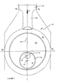
- an apparatus 10 for converting linear motion into rotary motion is shown as including a shaft 12 which is rotatable about a fixed axis 14 and carries a circular cam 16.
- the circular cam 16 is mounted eccentrically relative to the shaft 12 such that a central axis 18 of the cam 16 is spaced from the fixed axis 14.
- the cam 16 is rotatably mounted within a correspondingly dimensioned circular cavity 20 formed in a journal (in the form of disc 22) which is co-planar with the cam 16.
- the disc 22 is rotatably mounted within a housing 24 mounted for reciprocating motion along a second, rectilinear axis 26 in a direction transverse to the fixed axis 14 of the shaft 12.
- the reciprocating motion of the housing 24 along the rectilinear axis 26 is converted into rotation of the shaft 12.
- a connecting rod 28 is integrally formed with the housing 24, and is integrally formed at its other end to a piston 30.
- the apparatus 10 may be used in an internal combustion engine to convert linear motion of the piston 30 along the rectilinear axis 26 into rotary motion of the shaft 12.
- the apparatus 10 will now be further described in use in converting linear motion into rotary motion in an internal combustion engine, it is to be understood that the apparatus 10 may equally be used in applications to convert rotary motion into linear motion.
- the apparatus 10 may also be used in other specific applications requiring the conversion of rotary motion into linear motion or vice versa such as, for example, nautical steering systems and/or generators.
- the piston 30 In the case of converting linear motion into rotary motion in an internal combustion engine, the piston 30 is forced downwardly within a cylinder 32 along the rectilinear axis 26 in the direction indicated by arrow "A".
- the force acting on the piston 30 may be the result of combustion of a fuel (eg. such as petrol) in a combustion chamber formed above an upper surface of the piston 30, the fuel expanding as it combusts.
- a fuel eg. such as petrol
- the connecting rod 28 and the housing 24 are formed integrally with the piston 30, the connecting rod 28 and housing 24 are also forced downwardly along the rectilinear axis 26 by the force acting on the piston 30 during the power stroke.
- the housing 24 is constrained from movement other than along the rectilinear axis 26 by way of guide surfaces 34.
- the disc 22 is constrained to remaining within the circular cavity 20, and also to rotation about the central axis 18 of the cam 16, which in turn is constrained to rotation about the fixed axis 14 of the shaft 12, the fixed axis 14 being fixed at a location on the rectilinear axis 26, the disc 22, cam 16 and shaft 12 must all move within these constraints.
- These constraints define the characteristics of the cycle of apparatus 10, such as the relative durations and physical length of the power and compression strokes of the piston 30.
- the shaft 12 of the apparatus 10 is operatively connected to a drive transmission which may include a gearbox, tailshaft, differential and drive shafts in order to drive wheels of the automobile.
- a drive transmission which may include a gearbox, tailshaft, differential and drive shafts in order to drive wheels of the automobile.
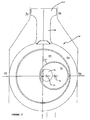
- FIG. 2 this shows an alternative apparatus for converting linear motion into rotary motion, in which like features are represented by like reference numerals.
- the main difference of the apparatus shown in Figure 2 when compared to the apparatus of Figure 1 is due to the spacing of the fixed axis 14 of the shaft 12 from the rectilinear axis 26.
- the cycle of the apparatus 10 becomes asymmetric, and this asymmetry can be designed to provide advantages in power output and/or efficiency of the internal combustion engine using the apparatus 10.
- the diameter of the cam 16 is sufficiently large such that, when the cam 16 is at the right-most position for its cycle (as shown in Figure 2 ), the left-hand side of the cam 16 extends past the rectilinear axis 26 into the left-hand half of the disc 22.
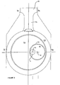
- FIG. 3 A further alternative apparatus 10 with an asymmetric cycle for converting linear motion into rotary motion is shown in Figure 3 , and has a relatively smaller cam 16 which fits within the right-hand half of the disc 22 when in its right-most position for its cycle, as shown.
- This apparatus 10 also has an asymmetric cycle by virtue of the spacing of the fixed axis 14 of the shaft 12 from the rectilinear axis 26. Accordingly, the power and compression strokes of the piston 30 of this apparatus 10 are of different relative durations owing to the asymmetry of the cycle. It should be noted however that, although both asymmetric, the specific characteristics of the cycles of the apparatuses shown in Figures 2 and 3 are different owing to the differences in geometry of the size and placement of the cam 16 and shaft 12, as discussed above.
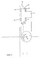
- FIG 4 A diagrammatic side view of the apparatus 10 of Figure 3 is shown in Figure 4 .
- This view shows a portion of the shaft 12 which has the cam 16 integrally mounted to it.
- the diagram shows that bearings 36 are used around the shaft 12 at either side of the cam 16 to facilitate rotational movement of the shaft 12 about its axis, and to support the shaft 12 from unwanted translational movement.
- the side view of the portion of the shaft 12 and cam 16 is shown above a front view of the shaft 12 and cam 16 for clarity.
- the use of bearings for supporting rotating components is well known. Other bearings may be used to support the cam 16 and disc 22.
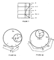
- Figure 5 shows a diagrammatic front view of yet another alternative apparatus 10 in which the fixed axis 14 of the shaft 12 is again spaced from the rectilinear axis 26 to provide an asymmetric cycle.
- Figures 6A to 6D illustrate configurations of the apparatus of Figure 5 shown for successive rotational positions of the shaft 14, at clockwise intervals of 90° (or ⁇ 2 radians ).
- Figure 6A shows the configuration of the apparatus 10 with the central axis 18 of the cam 16 to the right-hand side of the fixed axis 14 of the shaft 12;
- Figure 6B shows the configuration of the apparatus 10 with the central axis 18 of the cam 16 directly below the fixed axis 14 of the shaft 12;
- Figure 6C shows the configuration of the apparatus 10 with the central axis 18 of the cam 16 to the left-hand side of the fixed axis 14 of the shaft 12;
- Figure 6D shows the configuration of the apparatus 10 with the central axis 18 of the cam 16 directly above the fixed axis 14 of the shaft 12.
- Figure 7 shows that the compression stroke of the asymmetric cycle of the apparatus 10 depicted in Figures 5 to 6d occurs across 3 4 of the duration of the cycle (assuming the shaft 12 rotates with constant angular velocity - a reasonable assumption if a flywheel is coupled to the shaft 12), from the 0 radian position of the shaft 12 (relative to the rotation of the shaft 12 in the configuration shown in Figure 6A ) to the 3 ⁇ 2 radian position of the shaft 12 shown in Figure 6D .
- the power (expansion) stroke of the asymmetric cycle of the apparatus 10 occurs across a relative short period - just 1 4 of the duration of the cycle - between the configuration shown in Figure 6D and the configuration shown in Figure 6A . Accordingly, the mean velocity of the piston 30 during the expansion stroke is increased owing to the asymmetry of the present apparatus 10.
- the expansion stroke corresponds with the power stroke in an internal combustion engine (in a 2-stroke cycle every expansion stroke is a power stroke whereas in a 4-stroke cycle every second expansion stroke is a power stroke)
- the mean velocity of the piston 30 during the power stroke is thus increased by virtue of the asymmetry of the apparatus 10.
- FIGs 8A and 8B show relative rotation of the disc 22 through the four quadrants of rotation of the shaft 12 about the fixed axis 14 for both an apparatus having a symmetric cycle ( Figure 8A ) and for an apparatus having an asymmetric cycle ( Figure 8B ).
- Rotation of the disc 22 in each case is oscillatory in that the disc does not rotate through a complete rotation. Rather, as can be seen in Figure 8A the disc travels through a maximum arc of approximately 90° for the symmetric apparatus, and a maximum arc of approximately 170° for the asymmetric apparatus.
- the reference letters A, B, C and D show relative rotation of the disc 22 corresponding to the four quadrants of rotation of the shaft 12 about the fixed axis 14 in order, cycling through A, B, C, D, A, B, C, D, A, B, etc...
- the disc 22 rotates clockwise for the first three quadrants of clockwise rotation of the shaft 12, then through one large anticlockwise rotation for the final quadrant.
- Figure 8A shows that the disc 22 rotates clockwise for the first quadrant of clockwise rotation of the shaft 12, anticlockwise for the second quadrant, anticlockwise for the third quadrant, and clockwise for the fourth quadrant.
Landscapes
- Engineering & Computer Science (AREA)
- General Engineering & Computer Science (AREA)
- Mechanical Engineering (AREA)
- Chemical & Material Sciences (AREA)
- Combustion & Propulsion (AREA)
- Transmission Devices (AREA)
Claims (6)
- Verbrennungsmotor, umfassend:einen Kolben (30); undeine Vorrichtung (10) zum Umwandeln von linearer Bewegung in rotatorische Bewegung oder umgekehrt, wobei die Vorrichtung (10) eine Welle (12) umfasst, welche um eine feste Achse (14) rotierbar ist und einen kreisförmigen Nocken (16) trägt, welcher relativ zu der Achse (14) exzentrisch angebracht ist, wobei der Nocken (16) innerhalb eines kreisförmigen Lagers (22) rotierbar angebracht ist, wobei eine Rotationsachse des Nockens (16) relativ zu dem Lager (22) von einem Zentrum des Lagers (22) beabstandet ist, wobei das Lager (22) wiederum innerhalb eines Gehäuses (24) rotierbar angebracht ist, welches für eine Hin- und Herbewegung entlang einer zweiten Achse (26) in einer zu der Achse (14) der Welle (12) rechtwinkligen Richtung angebracht ist, wobei die Hin- und Herbewegung des Gehäuses (24) entlang der zweiten Achse (26) in eine Rotation der Welle (12) umgewandelt wird, oder eine Rotation der Welle (12) in eine Hin- und Herbewegung des Gehäuses (24) entlang der zweiten Achse (26) umgewandelt wird, wobei die zweite Achse (26) das Zentrum des Lagers (22) kreuzt, wobei die feste Achse (14) der Welle (12) von der zweiten Achse (26) beabstandet ist, und wobei das Gehäuse (24) fest an den Kolben (30) befestigt ist.
- Verbrennungsmotor nach Anspruch 1, wobei das Lager (22) dazu eingerichtet ist, dass eine Rotation des Lagers (22) relativ zu seinem Zentrum zwischen einer Rotation im Uhrzeigersinn und einer Rotation gegen den Uhrzeigersinn in Reaktion auf eine unidirektionale Rotation der Welle (12) relativ zu der Achse (14) der Welle (12) oszilliert.
- Verbrennungsmotor nach Anspruch 1, wobei das Lager (22) die Form einer Scheibe hat.
- Verbrennungsmotor nach Anspruch 1, wobei in Rotation der Welle (12) eine Konfiguration existiert, in welcher die feste Achse (14), die Rotationsachse des Nockens (16) relativ zu dem Lager (22) und das Zentrum des Lagers (22) in einer Linie rechtwinklig zu der zweiten Achse (26) ausgerichtet sind.
- Verbrennungsmotor nach Anspruch 1, wobei die Beabstandung der festen Achse (14) der Welle (12) von der zweiten Achse (26) derart ist, dass die Dauer eines Arbeitshubs des Kolbens (30) relativ zu einem Kompressionshub des Kolbens (30) verkürzt ist.
- Verbrennungsmotor nach Anspruch 5, wobei die Verkürzung der Dauer des Arbeitshubs in einem Anstieg in der durchschnittlichen Geschwindigkeit des Kolbens (30) über den Arbeitshub resultiert.
Applications Claiming Priority (4)
| Application Number | Priority Date | Filing Date | Title |
|---|---|---|---|
| AU2003903244A AU2003903244A0 (en) | 2003-06-26 | 2003-06-26 | Rotatory crank shaft |
| AU2003907214 | 2003-12-05 | ||
| AU2003270961A AU2003270961B1 (en) | 2003-06-26 | 2003-12-17 | Rotatory crank shaft |
| PCT/AU2004/000808 WO2004113682A1 (en) | 2003-06-26 | 2004-06-21 | Linear into rotatory or vice versa motion convertor |
Publications (3)
| Publication Number | Publication Date |
|---|---|
| EP1636460A1 EP1636460A1 (de) | 2006-03-22 |
| EP1636460A4 EP1636460A4 (de) | 2010-01-13 |
| EP1636460B1 true EP1636460B1 (de) | 2016-07-27 |
Family
ID=33544809
Family Applications (1)
| Application Number | Title | Priority Date | Filing Date |
|---|---|---|---|
| EP04737433.5A Expired - Lifetime EP1636460B1 (de) | 2003-06-26 | 2004-06-21 | Bewegungswandler zur umwandlung einer linear- in eine drehbewegung und umgekehrt |
Country Status (7)
| Country | Link |
|---|---|
| US (1) | US7503305B2 (de) |
| EP (1) | EP1636460B1 (de) |
| JP (1) | JP4205721B2 (de) |
| AU (1) | AU2003270961B1 (de) |
| CA (1) | CA2495393C (de) |
| NZ (1) | NZ542953A (de) |
| WO (2) | WO2004113681A1 (de) |
Families Citing this family (14)
| Publication number | Priority date | Publication date | Assignee | Title |
|---|---|---|---|---|
| RU2280771C2 (ru) * | 2004-05-19 | 2006-07-27 | Владимир Александрович Ворогушин | Устройство преобразования движения |
| FR2920212A1 (fr) * | 2007-08-22 | 2009-02-27 | Yves Darmon | Dispositif de conversion d'un mouvement lineaire en un mouvement rotatif et reciproquement |
| ATE481184T1 (de) * | 2008-07-01 | 2010-10-15 | Anlagentech Baumasch Ind | Schwingungserzeuger |
| WO2010105278A2 (en) * | 2009-03-13 | 2010-09-16 | Parsons Dashiell B | Systems for transmitting drive force |
| AU2012202154A1 (en) * | 2011-06-30 | 2013-01-17 | Exodus R&D International Pte Ltd | Desmodronic shaft and yoke assembly for translating linear to rotary motion |
| CN103987638B (zh) * | 2011-10-04 | 2016-09-14 | 格西集团公司 | 一种用于破坏在容器中的干燥颗粒材料的桥或结块的撞击件及其方法 |
| US8907659B2 (en) * | 2012-05-21 | 2014-12-09 | Chung Instrument Electronics Industrial Co., Ltd. | Retractable test probe |
| JP5953221B2 (ja) * | 2012-12-19 | 2016-07-20 | 株式会社村上開明堂 | アクチュエータ |
| CN103075480B (zh) * | 2013-01-23 | 2016-05-25 | 王敬达 | 一种转换运动轨迹的方法和装置 |
| US10617411B2 (en) * | 2015-12-01 | 2020-04-14 | Covidien Lp | Adapter assembly for surgical device |
| CN106121813A (zh) * | 2016-07-28 | 2016-11-16 | 张学新 | 无死角活塞式内燃机 |
| US11781601B2 (en) * | 2019-06-11 | 2023-10-10 | Ab Volvo Penta | Multi-plate clutch transmission and marine vehicle including a multi-plate clutch transmission |
| TR2021013880A1 (tr) | 2021-09-03 | 2023-03-21 | Gazi̇ Üni̇versi̇tesi̇ | Silindir yaslanmasız, piston-biyel-krank mekanizması. |
| BR102022015357A2 (pt) * | 2022-08-03 | 2024-02-15 | Manuel Exposito Carballada | Motor de pistões livres |
Family Cites Families (21)
| Publication number | Priority date | Publication date | Assignee | Title |
|---|---|---|---|---|
| US1867981A (en) * | 1930-08-18 | 1932-07-19 | Ora C Mudd | Mechanical movement |
| FR2233868A6 (de) * | 1973-06-14 | 1975-01-10 | Pailler Yves | |
| JPS5037964A (de) * | 1973-08-10 | 1975-04-09 | ||
| DE2545998A1 (de) * | 1974-10-15 | 1976-04-29 | Notario Luis Iturriaga | Compressor mit wechsellaeufigen kolben |
| DE2519908A1 (de) * | 1975-05-03 | 1976-11-11 | Juergen Dipl Ing Lambrecht | Hubkolbenmaschine mit exzentrischer nachfuehrung |
| DE2720284C3 (de) * | 1977-05-05 | 1981-05-27 | Huf, Franz, Prof. Dipl.-Ing., 7750 Konstanz | Schubkurbelsystem-Baureihe |
| SU1091649A1 (ru) * | 1981-04-10 | 1997-11-20 | Астраханский технический институт рыбной промышленности и хозяйства | Поршневая машина |
| US4411164A (en) | 1981-06-02 | 1983-10-25 | The United States Of America As Represented By The Secretary Of The Army | Rotary to recipricating motion translator |
| JPS59203801A (ja) | 1983-05-04 | 1984-11-19 | Kenji Matsuura | ピストン内にロ−タ−を有する原動機及び圧縮機 |
| DE3904716C2 (de) * | 1989-02-16 | 1994-01-05 | Heinrich Schiller | Hubkolbenverdichter oder -verbrennungsmotor mit Exzenterantrieb |
| GB9323291D0 (en) | 1993-11-11 | 1994-01-05 | Galvin George F | Crank mechanism |
| DE4035139A1 (de) | 1990-11-06 | 1992-05-07 | Josef Brucher | Exzenterwellenschieber |
| JPH04317461A (ja) | 1991-04-11 | 1992-11-09 | Kobelco Kaken:Kk | 高融点金属鋳造用鋳型材 |
| RU2064048C1 (ru) * | 1993-04-15 | 1996-07-20 | Василий Николаевич Маркочев | Поршневой двигатель |
| US5503038A (en) * | 1994-04-01 | 1996-04-02 | Aquino; Giovanni | Free floating multiple eccentric device |
| DE4445131C2 (de) | 1994-12-17 | 1997-02-20 | Max Liebich | Kurbelgetriebe, insbesondere für Verbrennungsmotoren |
| US5664464A (en) | 1995-01-10 | 1997-09-09 | Carson; Douglas Timothy | Low stress engine for converting motion between reciprocating and rotational motion |
| CN1067741C (zh) * | 1995-06-13 | 2001-06-27 | 辽宁大安发动机研究所 | 曲柄双圆滑块往复活塞式内燃机 |
| WO2000008325A1 (en) * | 1998-08-04 | 2000-02-17 | Oezdamar Hasan Basri | Eccentric and spring system for the internal and external combustion piston motors |
| US6202622B1 (en) * | 1998-10-22 | 2001-03-20 | Antonio C. Raquiza, Jr. | Crank system for internal combustion engine |
| US6629514B1 (en) * | 1999-06-22 | 2003-10-07 | Richard A. Gale | Two stroke gasoline engine with rotary valve enabling double acting power strokes and rotary air valve to lessen blowback |
-
2003
- 2003-12-17 AU AU2003270961A patent/AU2003270961B1/en not_active Ceased
-
2004
- 2004-06-16 WO PCT/AU2004/000787 patent/WO2004113681A1/en not_active Ceased
- 2004-06-21 CA CA002495393A patent/CA2495393C/en not_active Expired - Fee Related
- 2004-06-21 NZ NZ542953A patent/NZ542953A/en not_active IP Right Cessation
- 2004-06-21 US US10/519,957 patent/US7503305B2/en not_active Expired - Fee Related
- 2004-06-21 WO PCT/AU2004/000808 patent/WO2004113682A1/en not_active Ceased
- 2004-06-21 EP EP04737433.5A patent/EP1636460B1/de not_active Expired - Lifetime
- 2004-06-21 JP JP2005518240A patent/JP4205721B2/ja not_active Expired - Fee Related
Also Published As
| Publication number | Publication date |
|---|---|
| HK1088376A1 (en) | 2006-11-03 |
| JP2006515662A (ja) | 2006-06-01 |
| WO2004113682A1 (en) | 2004-12-29 |
| EP1636460A1 (de) | 2006-03-22 |
| US20050235764A1 (en) | 2005-10-27 |
| JP4205721B2 (ja) | 2009-01-07 |
| WO2004113681A1 (en) | 2004-12-29 |
| US7503305B2 (en) | 2009-03-17 |
| EP1636460A4 (de) | 2010-01-13 |
| NZ542953A (en) | 2008-01-31 |
| CA2495393A1 (en) | 2004-12-29 |
| CA2495393C (en) | 2008-02-19 |
| AU2003270961B1 (en) | 2004-06-24 |
Similar Documents
| Publication | Publication Date | Title |
|---|---|---|
| EP1636460B1 (de) | Bewegungswandler zur umwandlung einer linear- in eine drehbewegung und umgekehrt | |
| EP1255937B1 (de) | Hypozykloidischer motor | |
| KR960704180A (ko) | 크랭크 장치 및 기계장치(crank device and machinery) | |
| US4419057A (en) | Rotary piston motor | |
| EP2905448A1 (de) | Verbrennungsmotor mit variablem Verdichtungsverhältnis und Betriebsverfahren des Motors | |
| US20030183026A1 (en) | Apparatus for converting rotary to reciprocating motion and vice versa | |
| CN101680517B (zh) | 往复转动式动力转换设备 | |
| CN100453850C (zh) | 线性运动转变成旋转运动或者反之亦然的转换器 | |
| US20100031916A1 (en) | Hypocycloid Engine | |
| CA2385112A1 (en) | Conversion of rectilinear reciprocating motion into rotational motion | |
| HK1088376B (en) | Linear into rotatory or vice versa motion convertor | |
| RU95116876A (ru) | Бесшатунный механизм для преобразования возвратно-поступательного движения во вращательное поршневой машины | |
| WO2000066913A1 (en) | Power transmission apparatus | |
| WO2001021936A1 (en) | Double shaft high torque engine | |
| JP2004060769A (ja) | 動力機構 | |
| JPH062566A (ja) | 動力伝達装置 | |
| KR100880916B1 (ko) | 왕복회전 동력변환장치 | |
| SU1173108A1 (ru) | Устройство дл преобразовани вращательного движени в возвратно-поступательное и наоборот (его варианты) | |
| KR930021430A (ko) | 동력전달장치 | |
| WO1991005186A1 (en) | Multi-connecting rod reciprocating machine | |
| RU92002192A (ru) | Поршневая машина | |
| RU1788302C (ru) | Поршнева машина | |
| GB2251655A (en) | Rotary engine | |
| JPS60201161A (ja) | 運動方向変換装置 | |
| KR20010084446A (ko) | 내연기관의 출력 증가 장치 및 방법 |
Legal Events
| Date | Code | Title | Description |
|---|---|---|---|
| PUAI | Public reference made under article 153(3) epc to a published international application that has entered the european phase |
Free format text: ORIGINAL CODE: 0009012 |
|
| 17P | Request for examination filed |
Effective date: 20051027 |
|
| AK | Designated contracting states |
Kind code of ref document: A1 Designated state(s): AT BE BG CH CY CZ DE DK EE ES FI FR GB GR HU IE IT LI LU MC NL PL PT RO SE SI SK TR |
|
| AX | Request for extension of the european patent |
Extension state: AL HR LT LV MK |
|
| REG | Reference to a national code |
Ref country code: HK Ref legal event code: DE Ref document number: 1088376 Country of ref document: HK |
|
| A4 | Supplementary search report drawn up and despatched |
Effective date: 20091216 |
|
| RIC1 | Information provided on ipc code assigned before grant |
Ipc: F01B 9/02 20060101ALI20091210BHEP Ipc: F02B 75/32 20060101ALI20091210BHEP Ipc: F16H 21/22 20060101ALI20091210BHEP Ipc: F02F 7/00 20060101ALI20091210BHEP Ipc: F01B 9/06 20060101AFI20050106BHEP Ipc: F16H 21/18 20060101ALI20091210BHEP |
|
| 17Q | First examination report despatched |
Effective date: 20100423 |
|
| GRAP | Despatch of communication of intention to grant a patent |
Free format text: ORIGINAL CODE: EPIDOSNIGR1 |
|
| INTG | Intention to grant announced |
Effective date: 20160127 |
|
| GRAS | Grant fee paid |
Free format text: ORIGINAL CODE: EPIDOSNIGR3 |
|
| GRAA | (expected) grant |
Free format text: ORIGINAL CODE: 0009210 |
|
| AK | Designated contracting states |
Kind code of ref document: B1 Designated state(s): AT BE BG CH CY CZ DE DK EE ES FI FR GB GR HU IE IT LI LU MC NL PL PT RO SE SI SK TR |
|
| AX | Request for extension of the european patent |
Extension state: AL HR LT LV MK |
|
| REG | Reference to a national code |
Ref country code: GB Ref legal event code: FG4D |
|
| REG | Reference to a national code |
Ref country code: CH Ref legal event code: EP |
|
| REG | Reference to a national code |
Ref country code: AT Ref legal event code: REF Ref document number: 815973 Country of ref document: AT Kind code of ref document: T Effective date: 20160815 |
|
| REG | Reference to a national code |
Ref country code: IE Ref legal event code: FG4D |
|
| REG | Reference to a national code |
Ref country code: DE Ref legal event code: R096 Ref document number: 602004049663 Country of ref document: DE |
|
| REG | Reference to a national code |
Ref country code: LT Ref legal event code: MG9D |
|
| REG | Reference to a national code |
Ref country code: NL Ref legal event code: MP Effective date: 20160727 |
|
| REG | Reference to a national code |
Ref country code: AT Ref legal event code: MK05 Ref document number: 815973 Country of ref document: AT Kind code of ref document: T Effective date: 20160727 |
|
| PG25 | Lapsed in a contracting state [announced via postgrant information from national office to epo] |
Ref country code: FI Free format text: LAPSE BECAUSE OF FAILURE TO SUBMIT A TRANSLATION OF THE DESCRIPTION OR TO PAY THE FEE WITHIN THE PRESCRIBED TIME-LIMIT Effective date: 20160727 Ref country code: IT Free format text: LAPSE BECAUSE OF FAILURE TO SUBMIT A TRANSLATION OF THE DESCRIPTION OR TO PAY THE FEE WITHIN THE PRESCRIBED TIME-LIMIT Effective date: 20160727 Ref country code: NL Free format text: LAPSE BECAUSE OF FAILURE TO SUBMIT A TRANSLATION OF THE DESCRIPTION OR TO PAY THE FEE WITHIN THE PRESCRIBED TIME-LIMIT Effective date: 20160727 |
|
| PG25 | Lapsed in a contracting state [announced via postgrant information from national office to epo] |
Ref country code: AT Free format text: LAPSE BECAUSE OF FAILURE TO SUBMIT A TRANSLATION OF THE DESCRIPTION OR TO PAY THE FEE WITHIN THE PRESCRIBED TIME-LIMIT Effective date: 20160727 Ref country code: GR Free format text: LAPSE BECAUSE OF FAILURE TO SUBMIT A TRANSLATION OF THE DESCRIPTION OR TO PAY THE FEE WITHIN THE PRESCRIBED TIME-LIMIT Effective date: 20161028 Ref country code: BE Free format text: LAPSE BECAUSE OF FAILURE TO SUBMIT A TRANSLATION OF THE DESCRIPTION OR TO PAY THE FEE WITHIN THE PRESCRIBED TIME-LIMIT Effective date: 20160727 Ref country code: SE Free format text: LAPSE BECAUSE OF FAILURE TO SUBMIT A TRANSLATION OF THE DESCRIPTION OR TO PAY THE FEE WITHIN THE PRESCRIBED TIME-LIMIT Effective date: 20160727 Ref country code: PL Free format text: LAPSE BECAUSE OF FAILURE TO SUBMIT A TRANSLATION OF THE DESCRIPTION OR TO PAY THE FEE WITHIN THE PRESCRIBED TIME-LIMIT Effective date: 20160727 Ref country code: ES Free format text: LAPSE BECAUSE OF FAILURE TO SUBMIT A TRANSLATION OF THE DESCRIPTION OR TO PAY THE FEE WITHIN THE PRESCRIBED TIME-LIMIT Effective date: 20160727 Ref country code: PT Free format text: LAPSE BECAUSE OF FAILURE TO SUBMIT A TRANSLATION OF THE DESCRIPTION OR TO PAY THE FEE WITHIN THE PRESCRIBED TIME-LIMIT Effective date: 20161128 |
|
| PG25 | Lapsed in a contracting state [announced via postgrant information from national office to epo] |
Ref country code: RO Free format text: LAPSE BECAUSE OF FAILURE TO SUBMIT A TRANSLATION OF THE DESCRIPTION OR TO PAY THE FEE WITHIN THE PRESCRIBED TIME-LIMIT Effective date: 20160727 Ref country code: EE Free format text: LAPSE BECAUSE OF FAILURE TO SUBMIT A TRANSLATION OF THE DESCRIPTION OR TO PAY THE FEE WITHIN THE PRESCRIBED TIME-LIMIT Effective date: 20160727 |
|
| REG | Reference to a national code |
Ref country code: DE Ref legal event code: R097 Ref document number: 602004049663 Country of ref document: DE |
|
| PG25 | Lapsed in a contracting state [announced via postgrant information from national office to epo] |
Ref country code: BG Free format text: LAPSE BECAUSE OF FAILURE TO SUBMIT A TRANSLATION OF THE DESCRIPTION OR TO PAY THE FEE WITHIN THE PRESCRIBED TIME-LIMIT Effective date: 20161027 Ref country code: SK Free format text: LAPSE BECAUSE OF FAILURE TO SUBMIT A TRANSLATION OF THE DESCRIPTION OR TO PAY THE FEE WITHIN THE PRESCRIBED TIME-LIMIT Effective date: 20160727 Ref country code: DK Free format text: LAPSE BECAUSE OF FAILURE TO SUBMIT A TRANSLATION OF THE DESCRIPTION OR TO PAY THE FEE WITHIN THE PRESCRIBED TIME-LIMIT Effective date: 20160727 Ref country code: CZ Free format text: LAPSE BECAUSE OF FAILURE TO SUBMIT A TRANSLATION OF THE DESCRIPTION OR TO PAY THE FEE WITHIN THE PRESCRIBED TIME-LIMIT Effective date: 20160727 |
|
| PLBE | No opposition filed within time limit |
Free format text: ORIGINAL CODE: 0009261 |
|
| STAA | Information on the status of an ep patent application or granted ep patent |
Free format text: STATUS: NO OPPOSITION FILED WITHIN TIME LIMIT |
|
| 26N | No opposition filed |
Effective date: 20170502 |
|
| REG | Reference to a national code |
Ref country code: HK Ref legal event code: GR Ref document number: 1088376 Country of ref document: HK |
|
| PG25 | Lapsed in a contracting state [announced via postgrant information from national office to epo] |
Ref country code: SI Free format text: LAPSE BECAUSE OF FAILURE TO SUBMIT A TRANSLATION OF THE DESCRIPTION OR TO PAY THE FEE WITHIN THE PRESCRIBED TIME-LIMIT Effective date: 20160727 |
|
| REG | Reference to a national code |
Ref country code: DE Ref legal event code: R119 Ref document number: 602004049663 Country of ref document: DE |
|
| PG25 | Lapsed in a contracting state [announced via postgrant information from national office to epo] |
Ref country code: MC Free format text: LAPSE BECAUSE OF FAILURE TO SUBMIT A TRANSLATION OF THE DESCRIPTION OR TO PAY THE FEE WITHIN THE PRESCRIBED TIME-LIMIT Effective date: 20160727 |
|
| REG | Reference to a national code |
Ref country code: CH Ref legal event code: PL |
|
| GBPC | Gb: european patent ceased through non-payment of renewal fee |
Effective date: 20170621 |
|
| REG | Reference to a national code |
Ref country code: IE Ref legal event code: MM4A |
|
| REG | Reference to a national code |
Ref country code: FR Ref legal event code: ST Effective date: 20180228 |
|
| PG25 | Lapsed in a contracting state [announced via postgrant information from national office to epo] |
Ref country code: DE Free format text: LAPSE BECAUSE OF NON-PAYMENT OF DUE FEES Effective date: 20180103 Ref country code: IE Free format text: LAPSE BECAUSE OF NON-PAYMENT OF DUE FEES Effective date: 20170621 Ref country code: LI Free format text: LAPSE BECAUSE OF NON-PAYMENT OF DUE FEES Effective date: 20170630 Ref country code: LU Free format text: LAPSE BECAUSE OF NON-PAYMENT OF DUE FEES Effective date: 20170621 Ref country code: GB Free format text: LAPSE BECAUSE OF NON-PAYMENT OF DUE FEES Effective date: 20170621 Ref country code: CH Free format text: LAPSE BECAUSE OF NON-PAYMENT OF DUE FEES Effective date: 20170630 |
|
| PG25 | Lapsed in a contracting state [announced via postgrant information from national office to epo] |
Ref country code: FR Free format text: LAPSE BECAUSE OF NON-PAYMENT OF DUE FEES Effective date: 20170630 |
|
| PG25 | Lapsed in a contracting state [announced via postgrant information from national office to epo] |
Ref country code: HU Free format text: LAPSE BECAUSE OF FAILURE TO SUBMIT A TRANSLATION OF THE DESCRIPTION OR TO PAY THE FEE WITHIN THE PRESCRIBED TIME-LIMIT; INVALID AB INITIO Effective date: 20040621 |
|
| PG25 | Lapsed in a contracting state [announced via postgrant information from national office to epo] |
Ref country code: CY Free format text: LAPSE BECAUSE OF NON-PAYMENT OF DUE FEES Effective date: 20160727 |
|
| PG25 | Lapsed in a contracting state [announced via postgrant information from national office to epo] |
Ref country code: TR Free format text: LAPSE BECAUSE OF FAILURE TO SUBMIT A TRANSLATION OF THE DESCRIPTION OR TO PAY THE FEE WITHIN THE PRESCRIBED TIME-LIMIT Effective date: 20160727 |