EP1635098A2 - Verfahren und Spülkopf zum Freilegen von im Erdreich verlegten Anlagen - Google Patents
Verfahren und Spülkopf zum Freilegen von im Erdreich verlegten Anlagen Download PDFInfo
- Publication number
- EP1635098A2 EP1635098A2 EP05108401A EP05108401A EP1635098A2 EP 1635098 A2 EP1635098 A2 EP 1635098A2 EP 05108401 A EP05108401 A EP 05108401A EP 05108401 A EP05108401 A EP 05108401A EP 1635098 A2 EP1635098 A2 EP 1635098A2
- Authority
- EP
- European Patent Office
- Prior art keywords
- flushing head
- protective tube
- flushing
- clamping device
- head according
- Prior art date
- Legal status (The legal status is an assumption and is not a legal conclusion. Google has not performed a legal analysis and makes no representation as to the accuracy of the status listed.)
- Granted
Links
Images
Classifications
-
- H—ELECTRICITY
- H02—GENERATION; CONVERSION OR DISTRIBUTION OF ELECTRIC POWER
- H02G—INSTALLATION OF ELECTRIC CABLES OR LINES, OR OF COMBINED OPTICAL AND ELECTRIC CABLES OR LINES
- H02G1/00—Methods or apparatus specially adapted for installing, maintaining, repairing or dismantling electric cables or lines
- H02G1/06—Methods or apparatus specially adapted for installing, maintaining, repairing or dismantling electric cables or lines for laying cables, e.g. laying apparatus on vehicle
- H02G1/08—Methods or apparatus specially adapted for installing, maintaining, repairing or dismantling electric cables or lines for laying cables, e.g. laying apparatus on vehicle through tubing or conduit, e.g. rod or draw wire for pushing or pulling
- H02G1/086—Methods or apparatus specially adapted for installing, maintaining, repairing or dismantling electric cables or lines for laying cables, e.g. laying apparatus on vehicle through tubing or conduit, e.g. rod or draw wire for pushing or pulling using fluid as pulling means, e.g. liquid, pressurised gas or suction means
-
- F—MECHANICAL ENGINEERING; LIGHTING; HEATING; WEAPONS; BLASTING
- F16—ENGINEERING ELEMENTS AND UNITS; GENERAL MEASURES FOR PRODUCING AND MAINTAINING EFFECTIVE FUNCTIONING OF MACHINES OR INSTALLATIONS; THERMAL INSULATION IN GENERAL
- F16L—PIPES; JOINTS OR FITTINGS FOR PIPES; SUPPORTS FOR PIPES, CABLES OR PROTECTIVE TUBING; MEANS FOR THERMAL INSULATION IN GENERAL
- F16L1/00—Laying or reclaiming pipes; Repairing or joining pipes on or under water
- F16L1/024—Laying or reclaiming pipes on land, e.g. above the ground
- F16L1/028—Laying or reclaiming pipes on land, e.g. above the ground in the ground
Definitions
- the invention relates to a method for exposing buried in the ground facilities such as cables or pipes and a flushing head, at the front of a row of nozzles is arranged and at its rear side engages a provided with an internal duct driving rod, with which the flushing head between a starting pit and a Target mine is driven over the plant to be cleared.
- a flushing head of this type which is intended for trenchless removal of old cables, is known from DE 195 04 484 C1.
- the flushing head engages around the cable.
- a flushing liquid bentonite
- the propulsion of the flushing head via an attached at its rear linkage.
- the linkage is guided to the side of the cable.
- the pressurized rinse liquid is supplied through an internal channel within the boom.
- the cable is separated at a starting pit and a target pit.
- the rinsing is carried out starting from the starting pit, wherein the driving force is applied via the linkage and the rinsing liquid is fed under a pressure of 10 - 300 bar to the nozzles. Under multiple extension of the linkage and constant propulsive force of the cable section is exposed.
- the flushing head is removed, the Pole withdrawn to the starting pit and pulled out the cable section, where appropriate, a new cable can be fed with.
- the method is intended to allow the trenchless recovery and, if necessary, replacement of cables, so that the otherwise necessary extensive earthworks are avoided.
- it still has some disadvantages in practical use. So it happens that at a short distance above the cable laid Jardinabdecksteine, as they have been used for a long time, be loosened by the flushing of the soil between cable and cover stones and fall onto the cable, wherein the propulsion or a possible retraction obstruct the rinsing head or affect the mobility of the jacking linkage. Also, the extraction of the exposed cable section can be difficult.
- the rinsing head may be pushed by cable sleeves or other Aufwerfonne, z. B. attached to the cable identifiers that exist in old cables lead bands obstructed. This has meant that the recovery of a cable section in a designated section length often could not be done and another target pit had to be set.
- a protective tube made of steel over the pipe section has at its front a driving head for guiding the protective tube and is driven from behind by means of a hydraulically or pneumatically operated, remaining in the starting pit ram or press.
- Protective tube and jacking head are firmly welded together.
- means may be provided on the propellant head with which the space between the protective tube and the pipeline behind the propellant head can be flushed.
- the invention has for its object to provide a method and a suitable for carrying out the flushing head flushed with the laid in the ground facilities in larger sections and, if that is intended, can be recovered without interference.
- a protective tube clamped onto the flushing head via at least one clamping device is pulled along during the propulsion of the flushing head.
- a corresponding flushing head is designed so that it has at least one clamping device for a protective tube to be pulled along on its rear side.
- an inner sleeve is provided on the flushing head, on which the protective tube can be attached.
- the clamping device expediently consists of a cone-wedge device.
- the protective tube can be in the form of continuous material or as partial pipes to be welded (plastic or steel).
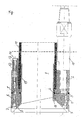
- the flushing head consists of a nozzle carrier 1 and a connecting element 2, which are connected to each other by welds 3 and 4.
- a connecting element 2 Through an annular recess in the nozzle carrier 1 and the connection element 2, an annular channel 5 is formed, which is connected via bores 6 with nozzles 7 in connection, which allow the exit of a rinsing agent on conical inner surfaces 8 of the nozzle carrier 1.
- Nozzle carrier 1 and connecting element 2 are annular, so that a passage 9 forms, with the rinsing head is moved via a line, not shown here.
- a linkage 10 is provided which is screwed to the connection element 2.
- the linkage 10 has a longitudinal channel through which the detergent is supplied.
- connection element 2 In order to be able to draw a protective tube 11 into the free-rinsed channel during flushing, the connection element 2 is provided with a clamping device consisting of a cone 12 and a wedge piece 13 which is pushed by a threaded screw 14 onto the cone 12.
- the protective tube 11, which was previously pushed onto an inner sleeve 15, is clamped with the cone 12 between the inner sleeve 15 and the inner surface of the connecting element 2.
- the inner sleeve 15 is attached to the nozzle carrier 1 after the application of the protective tube 11.
- several, distributed on the circumference of the connecting element 2 clamping devices may be provided.
- the inner sleeve 15 carries at a distance of about 7 cm circumferentially distributed, movable rollers 16 (or balls) with which the flushing head to obstacles, e.g. around a cable wrapped identification bands, can ascend without getting stuck.
- the flushing head is used, for example, for recovering an old pipeline, then in a proven manner a starting pit and at a distance of about 100 meters a target pit is excavated and the old pipeline is separated in these pits.
- a rigid guide tube material such as steel
- the flushing head including the clamped protective tube 11 is guided over the old line to be retrieved and advanced in the Spülbohrhabilit.
- the old line serves as a guide and the linkage 10 for applying the driving force and for conveying the detergent.
- the introduced under pressure, excess mixture of displaced soil and support material is flushed out in the direction of the starting pit, collected there and recycled or disposed of according to statutory provisions.
- the linkage 10 is withdrawn in the direction of the starting pit. Subsequently, the old line section can be pulled out.
- events such as the falling of stones, Lucasabdecksteinen or similar, can not affect the subsequent extraction of a line or other equipment, since they are stopped by the protective tube 11.
- the protective tube 11 can also take over the functions mentioned above.
- the extraction of the old line can be connected, if necessary, with the insertion of a new line.
- the protective tube 11 can remain according to the respective requirements or it is subsequently removed.
- the protective tube can be made of HDPE, PVC, steel or another tube that can be connected with restrained force.
Landscapes
- Engineering & Computer Science (AREA)
- General Engineering & Computer Science (AREA)
- Mechanical Engineering (AREA)
- Excavating Of Shafts Or Tunnels (AREA)
- Earth Drilling (AREA)
Abstract
Description
- Die Erfindung betrifft ein Verfahren zum Freilegen von im Erdreich verlegten Anlagen wie Kabeln oder Rohren und einen Spülkopf, an dessen Vorderseite eine Reihe von Düsen angeordnet ist und an dessen Rückseite ein mit einem Innenkanal versehenes Vortriebsgestänge angreift, mit dem der Spülkopf zwischen einer Startgrube und einer Zielgrube über die freizulegende Anlage vorgetrieben wird.
- Ein Spülkopf dieser Art, der zum grabenlosen Entfernen von alten Kabeln dienen soll, ist aus der DE 195 04 484 C1 bekannt. Der Spülkopf umgreift dabei das Kabel. Mit Hilfe der an seiner Vorderseite angeordneten Düsen wird das das Kabel umgebende Erdreich mittels einer Spülflüssigkeit (Bentonit) freigelegt. Der Vortrieb des Spülkopfes erfolgt über ein an seiner Rückseite angesetztes Gestänge. Das Gestänge wird seitlich neben dem Kabel geführt. Die unter Druck stehende Spülflüssigkeit wird durch einen Innenkanal innerhalb des Gestänges zugeführt.
- Um den Spülkopf auf das Kabel aufzubringen, wird das Kabel an einer Startgrube sowie einer Zielgrube getrennt. Das Freispülen erfolgt ausgehend von der Startgrube, wobei die Vortriebskraft über das Gestänge aufgebracht wird und die Spülflüssigkeit unter einem Druck von 10 - 300 bar zu den Düsen geführt wird. Unter mehrfacher Verlängerung des Gestänges und ständiger Vortriebskraft wird der Kabelabschnitt freigelegt. In der Zielgrube wird der Spülkopf entfernt, das Gestänge zur Startgrube zurückgezogen und der Kabelabschnitt herausgezogen, wobei gegebenenfalls ein neues Kabel mit eingezogen werden kann.
- Das Verfahren soll das grabenlose Bergen und gegebenenfalls Ersetzen von Kabeln erlauben, so dass die sonst nötigen umfangreichen Erdarbeiten vermieden werden. Es hat im praktischen Einsatz jedoch noch einige Nachteile. So kommt es vor, dass in einem kurzen Abstand über dem Kabel verlegte Kabelabdecksteine, wie sie lange Zeit verwendet wurden, durch das Freispülen des zwischen Kabel und Abdecksteinen befindlichen Erdreiches gelockert werden und und auf das Kabel fallen, wobei sie den Vortrieb oder ein eventuelles Zurückziehen des Spülkopfes behindern oder die Beweglichkeit des Vortriebsgestänges beeinträchtigen. Auch das Herausziehen des freigelegten Kabelabschnitts kann erschwert werden. Außerdem wird der Spülkopf beim Vortreiben möglicherweise durch Kabelmuffen oder andere Aufwerfungen, z. B. am Kabel angebrachte Kennungen, die bei alten Kabeln aus Bleibändern bestehen, behindert. Das hat dazu geführt, dass die Bergung eines Kabelabschnitts in einer vorgesehenen Abschnittslänge oftmals nicht erfolgen konnte und eine weitere Zielgrube gesetzt werden musste.
- Es hat deshalb nicht an Versuchen gefehlt, das Verfahren weiter zu verbessern. So ist mit der DE 1 002 932 A2 vorgeschlagen worden, zwischen Start- und Zielgrube entlang eines Kabels zunächst mehrere Bohrungen voranzutreiben und den Spülkopf in der Zielgrube an dem Bohrgestänge zu befestigen. Das Freispülen erfolgt dann in einer Rückwärtsbewegung zur Zielgrube. Das Verfahren ist durch das vorangehende Vortreiben mehrerer Bohrungen jedoch sehr aufwändig.
- In jüngster Zeit hat es auch Vorschläge gegeben, neben dem Spülkopf ein weiteres Werkzeug, z.B. eine Bohrkrone, vorzusehen, mit dem Fremdkörper in der Umgebung eines Kabels mechanisch zerkleinert werden können (DE 102 11 833 A1) oder den Spülbohrkopf mit einem zusätzlichen Rotationsantrieb zu versehen (DE 100 65 532 C1). Auch durch Änderung der Spülkopfgeometrie (DE 202 18 713 U1) soll das Freilegen eines Kabels verbessert werden.
- Zum Entfernen alter Rohrleitungen aus dem Erdreich ist es auch bekannt, von einer Startgrube aus zunächst ein Schutzrohr aus Stahl über den Rohrabschnitt aufzufahren. Das Schutzrohr weist an seine Vorderseite einen Vortriebskopf zur Führung des Schutzrohres auf und wird von hinten mittels einer hydraulisch oder pneumatisch betriebenen, in der Startgrube verbleibenden Ramme oder Presse vorgetrieben. Schutzrohr und Vortriebskopf sind fest miteinander verschweißt. Zusätzlich können am Vortriebskopf Mittel vorgesehen sein, mit denen der Raum zwischen dem Schutzrohr und der Rohrleitung hinter dem Vortriebskopf freigespült werden kann. Das Verfahren ist aber aufwändig und erfordert große Start- und Zielgruben, will man nicht sehr kurze Schutzrohrabschnitte verwenden, die alle zusammengeschweißt werden müssen. Im vorliegenden Verfahren soll deshalb auf das Spülbohrverfahren zurückgegriffen werden.
- Der Erfindung liegt die Aufgabe zugrunde, ein Verfahren und einen für dessen Durchführung geeigneten Spülkopf anzugeben, mit dem im Erdreich verlegte Anlagen in größeren Abschnitten freigespült und, sofern das beabsichtigt ist, ohne Beeinträchtigungen geborgen werden können.
- Erfindungsgemäß wird die Aufgabe gelöst durch die Merkmale der Ansprüche 1 und 5. Zweckmäßige Ausgestaltungen sind Gegenstand der Unteransprüche.
- Danach wird beim Vortrieb des Spülkopfes ein über mindestens eine Klemmeinrichtung am Spülkopf angeklemmtes Schutzrohr mitgezogen.
- Ein entsprechender Spülkopf ist dazu so ausgebildet, dass er an seiner Rückseite mindestens eine Klemmeinrichtung für ein mitzuziehendes Schutzrohr aufweist.
- Zweckmäßig ist am Spülkopf eine Innenhülse vorgesehen, auf die das Schutzrohr aufgesteckt werden kann. Die Klemmeinrichtung besteht zweckmäßig aus einer Konus-Keil-Einrichtung.
- Das Schutzrohr kann als Endlosmaterial oder auch als zu verschweißende Teilrohre (Kunststoff oder Stahl) vorliegen.
- Als ein weiteres erfindungsgemäßes Merkmal kann vorgesehen sein, dass an der Vorderseite des Spülkopfes im Bereich seines inneren Umfangs am Umfang verteilte, beweglich gelagerte Rollen oder Kugeln angeordnet sind, mit denen der Spülkopf auf eventuelle Hindernisse an einer freizulegenden Anlage auffahren kann.
- Mit dem Verfahren lassen sich bestehende, erdverlegte Anlagen wie Kabel, Rohre u. ä. verschiedener Leitungsverwaltungen ohne die bisher aufgetretenen Beeinträchtigungen grabenlos freilegen und darüber hinaus mit nachfolgend genannter Zielsetzung ummanteln:
- 1. unmittelbares Bergen von Leitungen nach der Ummantelung, z.B. bei bautechnisch schwierig auszuführenden Baumaßnahmen, beispielsweise in Bereichen geschützter Baumbestände
- 2. Späteres Bergen von Leitungen nach der Ummantelung
- 3. Schutzrohr nach der Leitungsbergung ziehen
- 4. Verbleib des Schutzrohres für eine spätere Leitungsbelegung
- 5. Schutzrohr nach Bergung einer Altanlage unmittelbar mit einer Neuanlage, z. B. einem weiteres Schutzrohr, einer Druckrohrleitung etc. belegen
- 6. Gewährleisten eines zusätzlichen Schutzes bei intakten oder beschädigten Leitungen
- 7. Gewährleisten einer zusätzlichen Abdichtung bei unter Druck stehenden Leitungen, z.B. Gas- oder Wasserleitungen
- Die Erfindung soll nachstehend anhand eines Ausführungsbeispiels näher erläutert werden. Die zugehörige Zeichnung zeigt einen erfindungsgemäßen Spülkopf in einer Querschnittsdarstellung.
- Der Spülkopf besteht aus einem Düsenträger 1 und einem Anschlusselement 2, die durch Schweißnähte 3 und 4 miteinander verbunden sind. Durch eine jeweils ringförmige Ausnehmung im Düsenträger 1 und im Anschlusselement 2 entsteht ein Ringkanal 5, der über Bohrungen 6 mit Düsen 7 in Verbindung steht, die den Austritt eines Spülmittels an konischen Innenflächen 8 des Düsenträgers 1 erlauben.
- Düsenträger 1 und Anschlusselement 2 sind ringförmig ausgebildet, so dass sich ein Durchgangskanal 9 bildet, mit dem der Spülkopf über eine hier nicht gezeigte Leitung bewegt wird. Zum Aufbringen der Vortriebskraft ist ein Gestänge 10 vorgesehen das mit dem Anschlusselement 2 verschraubt wird. Das Gestänge 10 hat einen Längskanal, über den das Spülmittel zugeführt wird.
- Um beim Spülbohren ein Schutzrohr 11 in den freigespülten Kanal mit einziehen zu können, ist das Anschlusselement 2 mit einer Klemmvorrichtung versehen, die aus einem Konus 12 und einem Keilstück 13 besteht, das von einer Gewindeschraube 14 auf den Konus 12 aufgeschoben wird. Das Schutzrohr 11 , das zuvor auf eine Innenhülse 15 aufgeschoben wurde, wird mit dem Konus 12 zwischen der Innenhülse 15 und der Innenfläche des Anschlusselements 2 festgeklemmt. Die Innenhülse 15 wird nach dem Aufbringen des Schutzrohres 11 an dem Düsenträger 1 befestigt. Gegebenenfalls können mehrere, am Umfang des Anschlusselements 2 verteilte Klemmeinrichtungen vorgesehen sein.
- In Höhe des Durchgangskanals 9 trägt die Innenhülse 15 im Abstand von ca. 7 cm am Umfang verteilte, bewegliche Rollen 16 (oder auch Kugeln), mit denen der Spülkopf auf Hindernisse, z.B. um ein Kabel herum gewickelte Kennungsbänder, auffahren kann, ohne hängen zu bleiben.
- Wird der Spülkopf beispielsweise zum Bergen einer Altleitung benutzt, so wird in bewährter Weise eine Startgrube und im Abstand von etwa 100 Meter eine Zielgrube ausgehoben und die Altleitung in diesen Gruben getrennt. Zu der Startgrube wird ein steifes Führungsrohr (Material z.B. Stahl) zur Führung des Gestänges 10 unter einem festgelegten Winkel zur Oberfläche des Geländes eingebaut, der einen vom Gestänge 10 abhängigen Biegeradius zum Erreichen der Waagerechten berücksichtigt. In der Startgrube wird der Spülkopf einschließlich des angeklemmten Schutzrohres 11 (Durchmesser etwa 80 mm bis 1000 mm) über die zu bergende Altleitung geführt und im Spülbohrverfahren vorgetrieben. Die Altleitung dient hierbei als Führung und das Gestänge 10 zum Aufbringen der Vortriebskraft sowie zum Befördern des Spülmittels. Über und innerhalb des Schutzrohres 11 wird das unter Druck eingebrachte, überschüssige Gemisch aus verdrängtem Boden- und Stützmaterial in Richtung der Startgrube ausgespült, dort aufgefangen und gemäß den gesetzlichen Bestimmungen verwertet oder entsorgt. Nach Ankunft des Spülkopfes in der Zielgrube wird dieser vom Gestänge 10 demontiert. Das Gestänge 10 wird in Richtung der Startgrube zurückgezogen. Anschließend kann der Altleitungsabschnitt herausgezogen werden. Während des Spülvorganges außerhalb des Schutzrohres 11 auftretende Ereignisse, z.B. das Herabfallen von Steinen, Kabelabdecksteinen o.ä., können das spätere Herausziehen einer Leitung oder anderer Anlagen nicht beeinträchtigen, da sie durch das Schutzrohr 11 aufgehalten werden. Darüber hinaus kann das Schutzrohr 11 auch die oben erwähnten Funktionen übernehmen.
- Das Herausziehen der Altleitung kann erforderlichenfalls mit dem Einziehen einer neuen Leitung verbunden werden. Das Schutzrohr 11 kann nach den jeweiligen Erfordernissen verbleiben oder es wird anschließend entfernt.
- Das Schutzrohr kann aus HDPE, PVC, Stahl oder einem anderen, längskraftschlüssig verbindbaren Rohr bestehen.
- Liste der Bezugszeichen
- 1
- Düsenträger
- 2
- Anschlusselement
- 3
- Schweißnaht
- 4
- Schweißnaht
- 5
- Ringkanal
- 6
- Bohrungen
- 7
- Düsen
- 8
- Innenfläche
- 9
- Durchgangskanal
- 10
- Gestänge
- 11
- Schutzrohr
- 12
- Konus
- 13
- Keilstück
- 14
- Gewindeschraube
- 15
- Innenhülse
- 16
- Rollen
Claims (12)
- Verfahren zum Freilegen von im Erdreich verlegten Anlagen wie Kabeln oder Rohren mit einem Spülkopf, an dessen Vorderseite eine Reihe von Düsen angeordnet ist und an dessen Rückseite ein mit einem Innenkanal versehenes Vortriebsgestänge angreift, mit dem der Spülkopf zwischen einer Startgrube und einer Zielgrube über die freizulegende Anlage vorgetrieben wird,
dadurch gekennzeichnet, dass
beim Vortrieb des Spülkopfes ein über mindestens eine Klemmeinrichtung am Spülkopf angeklemmtes Schutzrohr mitgezogen wird. - Verfahren nach Anspruch 1, dadurch gekennzeichnet, dass
das Schutzrohr auf eine Innenhülse des Spülkopfes aufgesteckt und mit der mindestens einen Klemmeinrichtung angeklemmt wird. - Verfahren nach Anspruch 1 oder 2, dadurch gekennzeichnet, dass
als Schutzrohr Rohrenden verwendet werden, die im Verlauf des Spülbohrens miteinander verschweißt werden. - Verfahren nach Anspruch 1 oder 2, dadurch gekennzeichnet, dass
als Schutzrohr ein Endlosrohr verwendet wird. - Spülkopf zum Freilegen von im Erdreich verlegten Anlagen wie Kabeln oder Rohren, an dessen Vorderseite eine Reihe von Düsen (7) angeordnet ist und an dessen Rückseite ein mit einem Innenkanal (9) versehenes Vortriebsgestänge (10) angreift, mit dem der Spülkopf zwischen einer Startgrube und einer Zielgrube über die freizulegende Anlage vorgetrieben wird, zur Durchführung des Verfahren nach einem der vorhergehenden Ansprüche, dadurch gekennzeichnet, dass
der Spülkopf an seiner Rückseite mindestens eine Klemmeinrichtung für ein mitzuziehendes Schutzrohr (11) aufweist. - Spülkopf nach Anspruch 5, dadurch gekennzeichnet, dass
das Schutzrohr (11) auf eine Innenhülse (15) aufsteckbar und mit der mindestens einen Klemmeinrichtung verklemmbar ist. - Spülkopf nach Anspruch 5 oder 6, dadurch gekennzeichnet, dass
die Klemmeinrichtung aus einer Konus-Keil-Einrichtung (12, 13) besteht. - Spülkopf nach einem der Ansprüche 5 bis 7, dadurch gekennzeichnet, dass
an seiner Vorderseite im Bereich seines inneren Umfangs (8) am Umfang verteilte beweglich gelagerte Rollen (16) oder Kugeln angeordnet sind. - Spülkopf nach einem der Ansprüche 5 bis 8, dadurch gekennzeichnet, dass
das Schutzrohr (11) flexibel ist. - Spülkopf nach einem der Ansprüche 5 bis 9, dadurch gekennzeichnet, dass
das Schutzrohr (11) aus Kunststoff besteht. - Spülkopf nach einem der Ansprüche 5 bis 10, dadurch gekennzeichnet, dass
das Schutzrohr (11) als Endlosmaterial vorliegt. - Spülkopf nach einem der Ansprüche 5 bis 10, dadurch gekennzeichnet, dass
das Schutzrohr (11) als zu verschweißende Teilrohre vorliegt.
Applications Claiming Priority (1)
| Application Number | Priority Date | Filing Date | Title |
|---|---|---|---|
| DE102004044747A DE102004044747A1 (de) | 2004-09-13 | 2004-09-13 | Verfahren und Spülkopf zum Freilegen von im Erdreich verlegten Anlagen |
Publications (3)
| Publication Number | Publication Date |
|---|---|
| EP1635098A2 true EP1635098A2 (de) | 2006-03-15 |
| EP1635098A3 EP1635098A3 (de) | 2008-10-08 |
| EP1635098B1 EP1635098B1 (de) | 2011-05-11 |
Family
ID=35519772
Family Applications (1)
| Application Number | Title | Priority Date | Filing Date |
|---|---|---|---|
| EP05108401A Not-in-force EP1635098B1 (de) | 2004-09-13 | 2005-09-13 | Verfahren und Spülkopf zum Freilegen von im Erdreich verlegten Anlagen |
Country Status (3)
| Country | Link |
|---|---|
| EP (1) | EP1635098B1 (de) |
| AT (1) | ATE509223T1 (de) |
| DE (1) | DE102004044747A1 (de) |
Cited By (4)
| Publication number | Priority date | Publication date | Assignee | Title |
|---|---|---|---|---|
| WO2009027429A2 (de) * | 2007-08-29 | 2009-03-05 | Evonik Degussa Gmbh | Umhüllte rohrleitung |
| DE202016106559U1 (de) | 2016-11-23 | 2017-01-24 | Volker Blankenburg | Vorrichtung zum Freilegen von im Erdreich verlegten Anlagen |
| DE102016122615A1 (de) | 2016-11-23 | 2018-05-24 | Volker Blankenburg | Verfahren und Vorrichtung zum Freilegen von im Erdreich verlegten Anlagen |
| CN108253196A (zh) * | 2018-04-16 | 2018-07-06 | 益辟西(上海)工程管理有限公司 | 套筒式顶进器 |
Citations (5)
| Publication number | Priority date | Publication date | Assignee | Title |
|---|---|---|---|---|
| DE19504484C1 (de) | 1995-02-10 | 1996-09-19 | Flowtex Technologie Import Von | Gerät zum Entfernen des ein oder mehrere unterirdisch verlegte Kabel umgebenden Erdreichs von den Kabeln |
| EP1002932A2 (de) | 1998-11-18 | 2000-05-24 | FlowTex Technologie GmbH & Co. KG | Verfahren und Vorrichtung zum grabenlosen Rohrleitungsaustausch |
| DE10065532C1 (de) | 2000-12-29 | 2002-08-08 | Tracto Technik | Vorrichtung und Verfahren zum Austauschen von Leitungen |
| DE20218713U1 (de) | 2002-12-02 | 2003-04-17 | Tracto Technik | Vorrichtung zum grabenlosen Austauschen von Leitungen |
| DE10211833A1 (de) | 2002-01-24 | 2003-08-07 | Tracto Technik | Vorrichtung zum grabenlosen Austauschen von Leitungen |
Family Cites Families (8)
| Publication number | Priority date | Publication date | Assignee | Title |
|---|---|---|---|---|
| US1887877A (en) * | 1931-06-01 | 1932-11-15 | George W Shaffer | Hose coupling |
| GB976421A (en) * | 1962-07-27 | 1964-11-25 | Edward Arthur Yates | Improvements relating to the laying of underground piping, especially water mains |
| US4923134A (en) * | 1987-11-02 | 1990-05-08 | Underground Technologies, Inc. | Self-propelled subsoil penetrating tool system |
| FR2716751B1 (fr) * | 1994-02-25 | 1996-03-29 | Gec Alsthom T & D Sa | Procédé et dispositif pour la pose d'une ligne de transport à isolation gazeuse. |
| FR2720873B1 (fr) * | 1994-06-06 | 1996-08-23 | Alain Pecot | Procédé et dispositif de pose d'un câble souterrain de télécommunications. |
| DE19802691C1 (de) * | 1998-01-24 | 2000-02-24 | Weiss Gmbh & Co Leonhard | Vorrichtung und Verfahren zum Bergen von Altkabeln |
| US6129486A (en) * | 1998-07-29 | 2000-10-10 | Putnam; Samuel W. | Pipe pulling and pushing apparatus and method |
| DE29823285U1 (de) * | 1998-12-04 | 1999-08-12 | Zent Frenger Ges Fuer Gebaeude | Vorrichtung zum Verlegen von flexiblem Endlosmaterial |
-
2004
- 2004-09-13 DE DE102004044747A patent/DE102004044747A1/de not_active Ceased
-
2005
- 2005-09-13 AT AT05108401T patent/ATE509223T1/de active
- 2005-09-13 EP EP05108401A patent/EP1635098B1/de not_active Not-in-force
Patent Citations (5)
| Publication number | Priority date | Publication date | Assignee | Title |
|---|---|---|---|---|
| DE19504484C1 (de) | 1995-02-10 | 1996-09-19 | Flowtex Technologie Import Von | Gerät zum Entfernen des ein oder mehrere unterirdisch verlegte Kabel umgebenden Erdreichs von den Kabeln |
| EP1002932A2 (de) | 1998-11-18 | 2000-05-24 | FlowTex Technologie GmbH & Co. KG | Verfahren und Vorrichtung zum grabenlosen Rohrleitungsaustausch |
| DE10065532C1 (de) | 2000-12-29 | 2002-08-08 | Tracto Technik | Vorrichtung und Verfahren zum Austauschen von Leitungen |
| DE10211833A1 (de) | 2002-01-24 | 2003-08-07 | Tracto Technik | Vorrichtung zum grabenlosen Austauschen von Leitungen |
| DE20218713U1 (de) | 2002-12-02 | 2003-04-17 | Tracto Technik | Vorrichtung zum grabenlosen Austauschen von Leitungen |
Cited By (10)
| Publication number | Priority date | Publication date | Assignee | Title |
|---|---|---|---|---|
| WO2009027429A2 (de) * | 2007-08-29 | 2009-03-05 | Evonik Degussa Gmbh | Umhüllte rohrleitung |
| WO2009027429A3 (de) * | 2007-08-29 | 2009-04-23 | Evonik Degussa Gmbh | Umhüllte rohrleitung |
| EA018498B1 (ru) * | 2007-08-29 | 2013-08-30 | Эвоник Дегусса Гмбх | Способ изготовления металлического трубопровода с защитным внешним покрытием и трубопровод, предназначенный для подземной прокладки бестраншейным методом и/или без использования песчаной постели |
| EA018498B9 (ru) * | 2007-08-29 | 2014-01-30 | Эвоник Дегусса Гмбх | Способ изготовления металлического трубопровода с защитным внешним покрытием и трубопровод, предназначенный для подземной прокладки бестраншейным методом и/или без использования песчаной постели |
| US9574700B2 (en) | 2007-08-29 | 2017-02-21 | Evonik Degussa Gmbh | Method of producing an underground pipeline |
| DE202016106559U1 (de) | 2016-11-23 | 2017-01-24 | Volker Blankenburg | Vorrichtung zum Freilegen von im Erdreich verlegten Anlagen |
| DE102016122615A1 (de) | 2016-11-23 | 2018-05-24 | Volker Blankenburg | Verfahren und Vorrichtung zum Freilegen von im Erdreich verlegten Anlagen |
| DE102016122615B4 (de) | 2016-11-23 | 2018-10-31 | Volker Blankenburg | Verfahren und Vorrichtung zum Freilegen von im Erdreich verlegten Anlagen |
| CN108253196A (zh) * | 2018-04-16 | 2018-07-06 | 益辟西(上海)工程管理有限公司 | 套筒式顶进器 |
| CN108253196B (zh) * | 2018-04-16 | 2024-01-16 | 南京龙创非开挖科技有限公司 | 套筒式顶进器 |
Also Published As
| Publication number | Publication date |
|---|---|
| EP1635098A3 (de) | 2008-10-08 |
| DE102004044747A1 (de) | 2006-03-30 |
| EP1635098B1 (de) | 2011-05-11 |
| ATE509223T1 (de) | 2011-05-15 |
Similar Documents
| Publication | Publication Date | Title |
|---|---|---|
| DE69534139T2 (de) | Installation von Kabelkanälen | |
| EP0953723B1 (de) | Aufweitvorrichtung | |
| EP1635098B1 (de) | Verfahren und Spülkopf zum Freilegen von im Erdreich verlegten Anlagen | |
| DE19504484C1 (de) | Gerät zum Entfernen des ein oder mehrere unterirdisch verlegte Kabel umgebenden Erdreichs von den Kabeln | |
| EP0622583B1 (de) | Verfahren und Rohrleitung zum Verlegen unterirdischer Rohrleitungen | |
| DE19843263A1 (de) | Verfahren zum Verlegen von Verlegeobjekten in Kanälen, Vorrichtung zur Durchführung des Verfahrens sowie Mittel zur Verwendung bei dem Verfahren | |
| DE3903864C1 (en) | Method and apparatus for redeveloping old pipes | |
| DE19802691C1 (de) | Vorrichtung und Verfahren zum Bergen von Altkabeln | |
| EP0748971B1 (de) | Verfahren und Vorrichtung zum grabenlosen Entfernen und Auswechseln erdverlegter Blei- und Kunststoffrohre | |
| EP1013874A2 (de) | Vorrichtung und Verfahren zum Ersetzen von Rohren | |
| EP0993540A1 (de) | Vorrichtung und verfahren zum herstellen von bohrlochverzweigungen | |
| DE202016106559U1 (de) | Vorrichtung zum Freilegen von im Erdreich verlegten Anlagen | |
| DE3501215C2 (de) | ||
| DE102016122615B4 (de) | Verfahren und Vorrichtung zum Freilegen von im Erdreich verlegten Anlagen | |
| EP1006638B1 (de) | Verfahren zur unterirdischen Verlegung von Kabeln und Versorgungsleitungen | |
| DE102017128404B4 (de) | Vorrichtung und Verfahren zur Inspektion und/oder Sanierung einer unterirdischen Rohrleitung | |
| EP0771593B1 (de) | Verfahren und Vorrichtung zum Freilegen und Reinigen von Litzen aus Stahldrähten | |
| DE4439597C2 (de) | Verfahren zur Reparatur von Schadstellen unterirdischer Abwasserkanäle | |
| EP3267540B1 (de) | Vorrichtung und verfahren zum einbringen von trassenband in den boden | |
| DE19929893C2 (de) | Verfahren zum grabenlosen Verlegen von Rohrleitungen und Kabeln | |
| DE10042725C1 (de) | Ausbauanker | |
| AT357946B (de) | Vorrichtung zum vortrieb eines aus mindestens einem rohrabschnitt bestehenden rohres im erdboden | |
| DE10144962B4 (de) | Reinigungswerkzeug für Kanäle | |
| EP1332269B1 (de) | Vorrichtung zum erzeugen einer umfangsbohrung | |
| EP0213259A2 (de) | Nachträgliche Deponieabdichtung |
Legal Events
| Date | Code | Title | Description |
|---|---|---|---|
| PUAI | Public reference made under article 153(3) epc to a published international application that has entered the european phase |
Free format text: ORIGINAL CODE: 0009012 |
|
| AK | Designated contracting states |
Kind code of ref document: A2 Designated state(s): AT BE BG CH CY CZ DE DK EE ES FI FR GB GR HU IE IS IT LI LT LU LV MC NL PL PT RO SE SI SK TR |
|
| AX | Request for extension of the european patent |
Extension state: AL BA HR MK YU |
|
| PUAL | Search report despatched |
Free format text: ORIGINAL CODE: 0009013 |
|
| AK | Designated contracting states |
Kind code of ref document: A3 Designated state(s): AT BE BG CH CY CZ DE DK EE ES FI FR GB GR HU IE IS IT LI LT LU LV MC NL PL PT RO SE SI SK TR |
|
| AX | Request for extension of the european patent |
Extension state: AL BA HR MK YU |
|
| RIC1 | Information provided on ipc code assigned before grant |
Ipc: F16L 1/028 20060101AFI20060117BHEP Ipc: H02G 1/06 20060101ALI20080902BHEP |
|
| 17P | Request for examination filed |
Effective date: 20090128 |
|
| AKX | Designation fees paid |
Designated state(s): AT BE BG CH CY CZ DE DK EE ES FI FR GB GR HU IE IS IT LI LT LU LV MC NL PL PT RO SE SI SK TR |
|
| GRAP | Despatch of communication of intention to grant a patent |
Free format text: ORIGINAL CODE: EPIDOSNIGR1 |
|
| GRAS | Grant fee paid |
Free format text: ORIGINAL CODE: EPIDOSNIGR3 |
|
| RIN1 | Information on inventor provided before grant (corrected) |
Inventor name: HELLMANN, ERNST Inventor name: HINRICHS, GUENTER |
|
| GRAA | (expected) grant |
Free format text: ORIGINAL CODE: 0009210 |
|
| AK | Designated contracting states |
Kind code of ref document: B1 Designated state(s): AT BE BG CH CY CZ DE DK EE ES FI FR GB GR HU IE IS IT LI LT LU LV MC NL PL PT RO SE SI SK TR |
|
| REG | Reference to a national code |
Ref country code: GB Ref legal event code: FG4D Free format text: NOT ENGLISH |
|
| REG | Reference to a national code |
Ref country code: CH Ref legal event code: EP |
|
| REG | Reference to a national code |
Ref country code: IE Ref legal event code: FG4D |
|
| REG | Reference to a national code |
Ref country code: DE Ref legal event code: R096 Ref document number: 502005011358 Country of ref document: DE Effective date: 20110622 |
|
| REG | Reference to a national code |
Ref country code: NL Ref legal event code: T3 |
|
| PG25 | Lapsed in a contracting state [announced via postgrant information from national office to epo] |
Ref country code: LT Free format text: LAPSE BECAUSE OF FAILURE TO SUBMIT A TRANSLATION OF THE DESCRIPTION OR TO PAY THE FEE WITHIN THE PRESCRIBED TIME-LIMIT Effective date: 20110511 Ref country code: SE Free format text: LAPSE BECAUSE OF FAILURE TO SUBMIT A TRANSLATION OF THE DESCRIPTION OR TO PAY THE FEE WITHIN THE PRESCRIBED TIME-LIMIT Effective date: 20110511 Ref country code: PT Free format text: LAPSE BECAUSE OF FAILURE TO SUBMIT A TRANSLATION OF THE DESCRIPTION OR TO PAY THE FEE WITHIN THE PRESCRIBED TIME-LIMIT Effective date: 20110912 |
|
| PG25 | Lapsed in a contracting state [announced via postgrant information from national office to epo] |
Ref country code: ES Free format text: LAPSE BECAUSE OF FAILURE TO SUBMIT A TRANSLATION OF THE DESCRIPTION OR TO PAY THE FEE WITHIN THE PRESCRIBED TIME-LIMIT Effective date: 20110822 Ref country code: SI Free format text: LAPSE BECAUSE OF FAILURE TO SUBMIT A TRANSLATION OF THE DESCRIPTION OR TO PAY THE FEE WITHIN THE PRESCRIBED TIME-LIMIT Effective date: 20110511 Ref country code: IS Free format text: LAPSE BECAUSE OF FAILURE TO SUBMIT A TRANSLATION OF THE DESCRIPTION OR TO PAY THE FEE WITHIN THE PRESCRIBED TIME-LIMIT Effective date: 20110911 Ref country code: GR Free format text: LAPSE BECAUSE OF FAILURE TO SUBMIT A TRANSLATION OF THE DESCRIPTION OR TO PAY THE FEE WITHIN THE PRESCRIBED TIME-LIMIT Effective date: 20110812 Ref country code: LV Free format text: LAPSE BECAUSE OF FAILURE TO SUBMIT A TRANSLATION OF THE DESCRIPTION OR TO PAY THE FEE WITHIN THE PRESCRIBED TIME-LIMIT Effective date: 20110511 Ref country code: CY Free format text: LAPSE BECAUSE OF FAILURE TO SUBMIT A TRANSLATION OF THE DESCRIPTION OR TO PAY THE FEE WITHIN THE PRESCRIBED TIME-LIMIT Effective date: 20110511 Ref country code: FI Free format text: LAPSE BECAUSE OF FAILURE TO SUBMIT A TRANSLATION OF THE DESCRIPTION OR TO PAY THE FEE WITHIN THE PRESCRIBED TIME-LIMIT Effective date: 20110511 |
|
| REG | Reference to a national code |
Ref country code: IE Ref legal event code: FD4D |
|
| PG25 | Lapsed in a contracting state [announced via postgrant information from national office to epo] |
Ref country code: EE Free format text: LAPSE BECAUSE OF FAILURE TO SUBMIT A TRANSLATION OF THE DESCRIPTION OR TO PAY THE FEE WITHIN THE PRESCRIBED TIME-LIMIT Effective date: 20110511 Ref country code: CZ Free format text: LAPSE BECAUSE OF FAILURE TO SUBMIT A TRANSLATION OF THE DESCRIPTION OR TO PAY THE FEE WITHIN THE PRESCRIBED TIME-LIMIT Effective date: 20110511 Ref country code: IE Free format text: LAPSE BECAUSE OF FAILURE TO SUBMIT A TRANSLATION OF THE DESCRIPTION OR TO PAY THE FEE WITHIN THE PRESCRIBED TIME-LIMIT Effective date: 20110511 |
|
| PG25 | Lapsed in a contracting state [announced via postgrant information from national office to epo] |
Ref country code: DK Free format text: LAPSE BECAUSE OF FAILURE TO SUBMIT A TRANSLATION OF THE DESCRIPTION OR TO PAY THE FEE WITHIN THE PRESCRIBED TIME-LIMIT Effective date: 20110511 Ref country code: RO Free format text: LAPSE BECAUSE OF FAILURE TO SUBMIT A TRANSLATION OF THE DESCRIPTION OR TO PAY THE FEE WITHIN THE PRESCRIBED TIME-LIMIT Effective date: 20110511 Ref country code: SK Free format text: LAPSE BECAUSE OF FAILURE TO SUBMIT A TRANSLATION OF THE DESCRIPTION OR TO PAY THE FEE WITHIN THE PRESCRIBED TIME-LIMIT Effective date: 20110511 Ref country code: PL Free format text: LAPSE BECAUSE OF FAILURE TO SUBMIT A TRANSLATION OF THE DESCRIPTION OR TO PAY THE FEE WITHIN THE PRESCRIBED TIME-LIMIT Effective date: 20110511 |
|
| PLBE | No opposition filed within time limit |
Free format text: ORIGINAL CODE: 0009261 |
|
| STAA | Information on the status of an ep patent application or granted ep patent |
Free format text: STATUS: NO OPPOSITION FILED WITHIN TIME LIMIT |
|
| BERE | Be: lapsed |
Owner name: GOTTFRIED PUHLMANN G.M.B.H. & CO. KG Effective date: 20110930 Owner name: HELLMANN, ERNST Effective date: 20110930 Owner name: FLOWTEX SERVICE HAMBURG G.- MBH & CO. KG Effective date: 20110930 |
|
| 26N | No opposition filed |
Effective date: 20120214 |
|
| PG25 | Lapsed in a contracting state [announced via postgrant information from national office to epo] |
Ref country code: MC Free format text: LAPSE BECAUSE OF NON-PAYMENT OF DUE FEES Effective date: 20110930 |
|
| PG25 | Lapsed in a contracting state [announced via postgrant information from national office to epo] |
Ref country code: IT Free format text: LAPSE BECAUSE OF FAILURE TO SUBMIT A TRANSLATION OF THE DESCRIPTION OR TO PAY THE FEE WITHIN THE PRESCRIBED TIME-LIMIT Effective date: 20110511 |
|
| REG | Reference to a national code |
Ref country code: DE Ref legal event code: R097 Ref document number: 502005011358 Country of ref document: DE Effective date: 20120214 |
|
| PG25 | Lapsed in a contracting state [announced via postgrant information from national office to epo] |
Ref country code: BE Free format text: LAPSE BECAUSE OF NON-PAYMENT OF DUE FEES Effective date: 20110930 |
|
| PG25 | Lapsed in a contracting state [announced via postgrant information from national office to epo] |
Ref country code: BG Free format text: LAPSE BECAUSE OF FAILURE TO SUBMIT A TRANSLATION OF THE DESCRIPTION OR TO PAY THE FEE WITHIN THE PRESCRIBED TIME-LIMIT Effective date: 20110811 |
|
| PG25 | Lapsed in a contracting state [announced via postgrant information from national office to epo] |
Ref country code: TR Free format text: LAPSE BECAUSE OF FAILURE TO SUBMIT A TRANSLATION OF THE DESCRIPTION OR TO PAY THE FEE WITHIN THE PRESCRIBED TIME-LIMIT Effective date: 20110511 |
|
| PG25 | Lapsed in a contracting state [announced via postgrant information from national office to epo] |
Ref country code: HU Free format text: LAPSE BECAUSE OF FAILURE TO SUBMIT A TRANSLATION OF THE DESCRIPTION OR TO PAY THE FEE WITHIN THE PRESCRIBED TIME-LIMIT Effective date: 20110511 |
|
| PGFP | Annual fee paid to national office [announced via postgrant information from national office to epo] |
Ref country code: AT Payment date: 20130919 Year of fee payment: 9 Ref country code: CH Payment date: 20130923 Year of fee payment: 9 Ref country code: LU Payment date: 20130925 Year of fee payment: 9 |
|
| PGFP | Annual fee paid to national office [announced via postgrant information from national office to epo] |
Ref country code: DE Payment date: 20131125 Year of fee payment: 9 |
|
| PGFP | Annual fee paid to national office [announced via postgrant information from national office to epo] |
Ref country code: GB Payment date: 20140923 Year of fee payment: 10 |
|
| PGFP | Annual fee paid to national office [announced via postgrant information from national office to epo] |
Ref country code: FR Payment date: 20140929 Year of fee payment: 10 |
|
| PGFP | Annual fee paid to national office [announced via postgrant information from national office to epo] |
Ref country code: NL Payment date: 20140922 Year of fee payment: 10 |
|
| REG | Reference to a national code |
Ref country code: DE Ref legal event code: R119 Ref document number: 502005011358 Country of ref document: DE |
|
| PG25 | Lapsed in a contracting state [announced via postgrant information from national office to epo] |
Ref country code: LU Free format text: LAPSE BECAUSE OF NON-PAYMENT OF DUE FEES Effective date: 20140913 |
|
| REG | Reference to a national code |
Ref country code: CH Ref legal event code: PL |
|
| REG | Reference to a national code |
Ref country code: AT Ref legal event code: MM01 Ref document number: 509223 Country of ref document: AT Kind code of ref document: T Effective date: 20140913 |
|
| REG | Reference to a national code |
Ref country code: DE Ref legal event code: R119 Ref document number: 502005011358 Country of ref document: DE Effective date: 20150401 |
|
| PG25 | Lapsed in a contracting state [announced via postgrant information from national office to epo] |
Ref country code: DE Free format text: LAPSE BECAUSE OF NON-PAYMENT OF DUE FEES Effective date: 20150401 Ref country code: LI Free format text: LAPSE BECAUSE OF NON-PAYMENT OF DUE FEES Effective date: 20140930 Ref country code: CH Free format text: LAPSE BECAUSE OF NON-PAYMENT OF DUE FEES Effective date: 20140930 |
|
| PG25 | Lapsed in a contracting state [announced via postgrant information from national office to epo] |
Ref country code: AT Free format text: LAPSE BECAUSE OF NON-PAYMENT OF DUE FEES Effective date: 20140913 |
|
| GBPC | Gb: european patent ceased through non-payment of renewal fee |
Effective date: 20150913 |
|
| REG | Reference to a national code |
Ref country code: NL Ref legal event code: MM Effective date: 20151001 |
|
| REG | Reference to a national code |
Ref country code: FR Ref legal event code: ST Effective date: 20160531 |
|
| PG25 | Lapsed in a contracting state [announced via postgrant information from national office to epo] |
Ref country code: GB Free format text: LAPSE BECAUSE OF NON-PAYMENT OF DUE FEES Effective date: 20150913 |
|
| PG25 | Lapsed in a contracting state [announced via postgrant information from national office to epo] |
Ref country code: FR Free format text: LAPSE BECAUSE OF NON-PAYMENT OF DUE FEES Effective date: 20150930 Ref country code: NL Free format text: LAPSE BECAUSE OF NON-PAYMENT OF DUE FEES Effective date: 20151001 |