EP1633956B1 - Rotary-piston machine - Google Patents
Rotary-piston machine Download PDFInfo
- Publication number
- EP1633956B1 EP1633956B1 EP04736841A EP04736841A EP1633956B1 EP 1633956 B1 EP1633956 B1 EP 1633956B1 EP 04736841 A EP04736841 A EP 04736841A EP 04736841 A EP04736841 A EP 04736841A EP 1633956 B1 EP1633956 B1 EP 1633956B1
- Authority
- EP
- European Patent Office
- Prior art keywords
- rotation element
- engine
- rotation
- cavity
- casing
- Prior art date
- Legal status (The legal status is an assumption and is not a legal conclusion. Google has not performed a legal analysis and makes no representation as to the accuracy of the status listed.)
- Expired - Lifetime
Links
- 239000012530 fluid Substances 0.000 claims abstract description 46
- 238000007906 compression Methods 0.000 claims description 61
- 230000006835 compression Effects 0.000 claims description 60
- 238000002485 combustion reaction Methods 0.000 claims description 34
- 230000007423 decrease Effects 0.000 claims 2
- 239000007789 gas Substances 0.000 description 67
- 238000007789 sealing Methods 0.000 description 15
- 238000004519 manufacturing process Methods 0.000 description 7
- 239000000446 fuel Substances 0.000 description 5
- 239000000463 material Substances 0.000 description 4
- QVGXLLKOCUKJST-UHFFFAOYSA-N atomic oxygen Chemical compound [O] QVGXLLKOCUKJST-UHFFFAOYSA-N 0.000 description 3
- 238000000034 method Methods 0.000 description 3
- 239000000203 mixture Substances 0.000 description 3
- 239000001301 oxygen Substances 0.000 description 3
- 229910052760 oxygen Inorganic materials 0.000 description 3
- 230000009467 reduction Effects 0.000 description 3
- 230000008901 benefit Effects 0.000 description 2
- 238000004364 calculation method Methods 0.000 description 2
- 230000008859 change Effects 0.000 description 2
- 238000002347 injection Methods 0.000 description 2
- 239000007924 injection Substances 0.000 description 2
- 230000007246 mechanism Effects 0.000 description 2
- 230000008569 process Effects 0.000 description 2
- 229910000831 Steel Inorganic materials 0.000 description 1
- 239000002131 composite material Substances 0.000 description 1
- 238000000205 computational method Methods 0.000 description 1
- 238000001816 cooling Methods 0.000 description 1
- 230000008030 elimination Effects 0.000 description 1
- 238000003379 elimination reaction Methods 0.000 description 1
- 230000005484 gravity Effects 0.000 description 1
- 238000005184 irreversible process Methods 0.000 description 1
- 238000012423 maintenance Methods 0.000 description 1
- 239000010959 steel Substances 0.000 description 1
- 238000009423 ventilation Methods 0.000 description 1
Images









Classifications
-
- F—MECHANICAL ENGINEERING; LIGHTING; HEATING; WEAPONS; BLASTING
- F01—MACHINES OR ENGINES IN GENERAL; ENGINE PLANTS IN GENERAL; STEAM ENGINES
- F01C—ROTARY-PISTON OR OSCILLATING-PISTON MACHINES OR ENGINES
- F01C3/00—Rotary-piston machines or engines with non-parallel axes of movement of co-operating members
- F01C3/02—Rotary-piston machines or engines with non-parallel axes of movement of co-operating members the axes being arranged at an angle of 90 degrees
-
- F—MECHANICAL ENGINEERING; LIGHTING; HEATING; WEAPONS; BLASTING
- F01—MACHINES OR ENGINES IN GENERAL; ENGINE PLANTS IN GENERAL; STEAM ENGINES
- F01C—ROTARY-PISTON OR OSCILLATING-PISTON MACHINES OR ENGINES
- F01C3/00—Rotary-piston machines or engines with non-parallel axes of movement of co-operating members
- F01C3/02—Rotary-piston machines or engines with non-parallel axes of movement of co-operating members the axes being arranged at an angle of 90 degrees
- F01C3/025—Rotary-piston machines or engines with non-parallel axes of movement of co-operating members the axes being arranged at an angle of 90 degrees of intermeshing engagement type, i.e. with engagement of co-operating members similar to that of toothed gearing
-
- F—MECHANICAL ENGINEERING; LIGHTING; HEATING; WEAPONS; BLASTING
- F01—MACHINES OR ENGINES IN GENERAL; ENGINE PLANTS IN GENERAL; STEAM ENGINES
- F01C—ROTARY-PISTON OR OSCILLATING-PISTON MACHINES OR ENGINES
- F01C1/00—Rotary-piston machines or engines
- F01C1/08—Rotary-piston machines or engines of intermeshing engagement type, i.e. with engagement of co- operating members similar to that of toothed gearing
-
- F—MECHANICAL ENGINEERING; LIGHTING; HEATING; WEAPONS; BLASTING
- F01—MACHINES OR ENGINES IN GENERAL; ENGINE PLANTS IN GENERAL; STEAM ENGINES
- F01C—ROTARY-PISTON OR OSCILLATING-PISTON MACHINES OR ENGINES
- F01C1/00—Rotary-piston machines or engines
- F01C1/08—Rotary-piston machines or engines of intermeshing engagement type, i.e. with engagement of co- operating members similar to that of toothed gearing
- F01C1/082—Details specially related to intermeshing engagement type machines or engines
- F01C1/084—Toothed wheels
-
- F—MECHANICAL ENGINEERING; LIGHTING; HEATING; WEAPONS; BLASTING
- F01—MACHINES OR ENGINES IN GENERAL; ENGINE PLANTS IN GENERAL; STEAM ENGINES
- F01C—ROTARY-PISTON OR OSCILLATING-PISTON MACHINES OR ENGINES
- F01C20/00—Control of, monitoring of, or safety arrangements for, machines or engines
- F01C20/18—Control of, monitoring of, or safety arrangements for, machines or engines characterised by varying the volume of the working chamber
- F01C20/20—Control of, monitoring of, or safety arrangements for, machines or engines characterised by varying the volume of the working chamber by changing the form of the inner or outlet contour of the working chamber
-
- F—MECHANICAL ENGINEERING; LIGHTING; HEATING; WEAPONS; BLASTING
- F01—MACHINES OR ENGINES IN GENERAL; ENGINE PLANTS IN GENERAL; STEAM ENGINES
- F01C—ROTARY-PISTON OR OSCILLATING-PISTON MACHINES OR ENGINES
- F01C20/00—Control of, monitoring of, or safety arrangements for, machines or engines
- F01C20/24—Control of, monitoring of, or safety arrangements for, machines or engines characterised by using valves for controlling pressure or flow rate, e.g. discharge valves
Definitions
- This invention relates to rotary engines
- compressors are well known devices.
- One type of compressor is the reciprocating compressor.
- Reciprocating compressors have the advantage that they are able to operate at high pressures.
- reciprocating compressors have a large, number of moving parts and are therefore relatively complex devices.
- One other type of compressor, the Roots compressor has rotary instead of reciprocating motion and its resulting simplicity means that it has few moving parts and is reliable.
- this type of compressor has its disadvantages.
- One such disadvantage is that it relies on "back-compression" to raise the pressure of the pumped gases. This means that no compression is performed on the low pressure input gases until they come into contact and mix with the higher pressure gases within the compressor. This irreversible process is inefficient, and leads to a higher drive power requirement and elevated air outlet temperatures.
- Lysholm compressor Another type of rotary compressor, the Lysholm compressor, employs internal compression to overcome the problems caused by "back compression".
- these compressors are significantly more efficient.
- their performance depends in large measure upon maintaining very small clearances between the moving elements, thus presenting considerable manufacturing problems. Imperfect sealing between the elements leads to back-leakage of the gas, limiting the pressures that can be attained using a single compressor.
- Compressors of the types discussed above are used in internal combustion engines.
- rotary compressors of the Roots, single-screw or Lysholm type are used in rotary engines, together with a corresponding expander mechanism that allows work to be extracted during expansion of the hot, pressurised gases.
- Rotary engines like rotary compressors, can have fewer moving parts and are thus more reliable than their reciprocating equivalents. Production and maintenance costs are also potentially lower.
- rotary engines are also less noisy and can achieve more combustion cycles per second compared to reciprocating engines, thus leading to a superior power to weight ratio.
- the idealised cycle that most rotary internal combustion engines approximate is the Otto cycle.
- One disadvantage of the Otto cycle is that the amount of work that can be extracted from the hot, pressurised gases is limited because the expansion ratio of the engine cannot exceed its compression ratio. The gases at the end of the Otto cycle's isentropic expansion step could do more work if further expansion to ambient pressure was allowed.
- This disadvantage is overcome in the idealised cycle known as the Atkinson-Miller cycle.
- the Atkinson-Miller cycle allows isentropic expansion to ambient pressure, and thus compression and expansion ratios that can be different.
- a number of rotary internal combustion engines using the Atkinson-Miller cycle have been proposed. However, these engine designs typically have many moving parts, or use parts that are difficult to manufacture.
- Advantageous rotary engine designs are capable of high compression ratios so that they may be used in compression ignition engines such as diesel engines.
- the power output of a rotary engine should be smooth and continuous, with minimal vibration. Noise and mechanical wear should be minimal.
- Various single screw rotary engines are well known in which compression and expansion occur in helical shaped channels which are formed in the surface a rotatable block. Separate working chambers are defined by the helical channel, a surface surrounding the rotatable block which seals the helical channel, and wheels having teeth or vanes which mesh with the helical channel.
- GB653185 discloses a rotary engine in which compression and expansion are achieved by providing a helical channel of varying depth and in which varying fractions of the wheel teeth or vanes define the working chambers.
- the tip of a tooth or vane remains within the channel, and the tooth or vane is always in contact with the gas in the working chamber.
- the shape of the wheel teeth or vanes does not significantly affect the compression or expansion ratio of the engine, and compression and expansion are performed in different parts of the engine:
- a rotary engine for use with compressible fluids, the engine comprising: a first rotation element mounted to rotate about a first axis; a casing having a surface enclosing at least a part of the first rotation element, an elongate cavity of varying cross sectional area being defined between a surface of the first rotation element and the casing surface and varying around the first axis depending on the radius of the first rotation element; and a plurality of second rotation elements mounted to rotate about respective different second axes, each second rotation element being mounted to project through a slot in the casing surface and to cooperate with the first rotation element surface so as to divide the cavity into adjacent working portions, wherein each second rotation element comprises a plurality of projecting portions having respective different radii about the second axis, the different radii causing the projecting portions to project into the cavity by respective different amounts, so that the volumes of the working portions vary as the first and second rotation elements rotate, wherein, in use, fluids in a working portion
- the first rotation element and each of the second rotation elements have a variable radius.
- the casing surface which has a constant radius, and the first rotation element surface therefore define a cavity that extends around the first axis.
- the cavity also rotates about the first axis.
- Each of the second rotation elements project through the casing surface.
- rotation of the first rotation element and each of the second rotation elements is co-ordinated so that they mesh together to provide a seal.
- Each of the second rotation elements thus define a number of working portions of the cavity. Working portions may also be defined by the first rotation element where its radius is at a maximum by providing a seal with the casing.
- the volumes of the working portions of the cavity change, thus providing compression or expansion of a fluid within.
- a rotary engine can thus be realised having a number of desirable qualities while at the same time being simple to manufacture and use.
- the rotary engine relies on internal compression thus avoiding the disadvantages associated with 'back compression', such as inefficiency.
- the simplicity of the design allows effective sealing between the various elements of the rotary engine thus avoiding the manufacturing complexity and other problems associated with known internal compression rotary engines.
- the first and second rotation elements each comprise a plurality of integral segments each having different radii.
- these segments are the projecting portions.
- the second rotation elements are distributed around the casing surface, each second rotation element being mounted to rotate about a respective axis that is perpendicular to both the first axis and the radius of the casing surface.
- a number of working portions of the cavity can be defined, and a compression and/or expansion process can be performed simultaneously in each.
- the first rotation element may be internal to the casing surface with the plurality of second rotation elements being external to the casing surface.
- the first rotation element will be substantially cylindrical.
- the first rotation element may be external to the casing surface with the plurality of second rotation elements being internal to the casing surface.
- the first rotation element will substantially take the form of an annulus.
- the rotary engine performs compression followed by expansion. Rotation of the first rotation element and each of the plurality of second rotation elements causes the volume of the working portions of the cavity to reduce and then increase during each cycle. Since compression and expansion are performed by different portions of the first rotation element surface, an engine having different compression and expansion ratios can be realised.
- the rotary engine also comprises ignition means for ignition of a compressed fluid prior to expansion.
- the ignition means may comprise a spark plug.
- the gases are a fuel and oxygen mix
- a spark plug may induce combustion, as in a conventional petrol engine.
- the gases include highly pressurised oxygen; the injection of fuel itself may induce combustion, as in a conventional diesel engine.
- Other means of causing a sudden further increase in pressure may be used, such as the injection of a small volume of high pressure, low temperature gas. The sudden increase in pressure allows more work to be extracted during expansion than was used in compression, thus powering the engine.
- the first rotation element also comprises at least one passage for fluid inlet or fluid outlet.
- the first rotation element may even comprise passages for both fluid inlet and fluid outlet. In this way, fluids can be drawn or forced into the working portions of the cavity, or exhausted or released from the working portions of the cavity.
- the casing may also comprise at least one side valve, each of the at least one side valves being operative as a fluid inlet or fluid outlet only when adjacent to a working portion of the cavity, each of the at least one side valves being adjacent to a working portion of the cavity for a fraction of a cycle of the device.
- the rotary engine may therefore be designed so that the area of the casing containing a side valve only forms a boundary of a working portion of the cavity when fluid inlet or fluid outlet is desired.
- each of the at least one side valves is operative to vary the flow rate of a fluid into a working portion of the cavity, to vary the pressure of fluid within a working portion of the cavity, or to vary a compression or expansion ratio of the rotary engine.
- Side valves may therefore provide a way of controlling the operation of the rotary engine.
- closed loop feedback control is used to control the operation of each of the at least one side valves, the closed loop feedback control being based on an operating parameter such as fluid inlet pressure, fluid outlet pressure and rotary speed.
- an operating parameter such as fluid inlet pressure, fluid outlet pressure and rotary speed.
- This invention also provides a rotary engine comprising two of the rotary devices described above.
- the respective second rotation elements may be arranged so that the net forces on the first rotation element are minimised. For example, this could be achieved by providing a second rotation element from each of the rotary engines on opposite sides of the integral first rotation element.
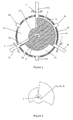
- Figures 1 to 5 show a first rotary engine according to the invention.
- the first rotary engine comprises a first rotation element 1, a casing 2, three second rotation elements 3a, 3b, 3c, three spark plugs 8a, 8b, 8c and a power output shaft (not shown).
- the first rotation element 1 is mounted to rotate about a first axis 6.
- the first rotation element 1 is a substantially cylindrical block of material, but having large variations in radius.
- the first rotation element 1 is made from steel, although those skilled in the art will understand that it may advantageously be made from other materials. Suitable materials for the other described components of the first rotary engine will also be known to those skilled in the art.
- the substantially cylindrical first rotation element 1 is essentially formed from four segments each having a different radius: a sealing segment 1a, a compression segment 1b, a combustion segment 1c and an expansion segment 1 d.
- the sealing segment 1 a spans a very small angle about the first axis 6 but has the largest radius.
- the compression, combustion and expansion segments 1b, 1 c, 1d each span slightly less than 120° about the first axis.
- the first rotation element 1 also comprises a fluid inlet passage 4 and a fluid outlet passage 9 adjacent to the sealing segment 1a.
- the casing 2 includes a substantially cylindrical surface of constant radius centred about the first axis 6 and partially enclosing the first rotation element 1.
- the casing 2 also has end walls 2a that prevent axial movement of the first rotation element 1 along the first axis 6.
- the end walls 2a also provide a seal between the casing 2 and the ends of the first rotation element 1.
- a cavity 5a, 5b, 5c is defined between the first rotation element 1 and the casing 2.
- the cross sectional area of the cavity 5a, 5b, 5c varies around the first axis 6 depending on the radius of the first rotation element 1.
- the cross sectional area of the cavity is small where it is adjacent to the combustion segment 1 c, and the cross sectional area of the cavity is large where it is adjacent to the expansion segment 1d.
- the sealing segment 1a is instead in contact with the casing 2 to provide a seal.
- the sealing segment 1a also forms the beginning and end of the cavity 5a, 5b, 5c.
- the cavity 5a, 5b, 5c also rotates.
- the three second rotation elements 3a, 3b, 3c are each mounted around the casing 2 at 120° intervals about the first axis 6.
- the second rotation elements 3a, 3b, 3c are all mounted at the same axial distance from the ends of the casing 2.
- the second rotation elements 3a, 3b, 3c are each mounted to rotate about respective axes that are perpendicular to the first axis 6 and a radius of the first rotation element 1.
- they each project through the casing 2 into the cavity 5a, 5b, 5c by varying amounts.
- a seal is formed between each of the second rotation elements 3a, 3b, 3c and the casing 2.
- Figure 3 shows a side profile of one of the second rotation elements 3a, 3b, 3c and the axis 7 about which it rotates.
- Figures 4 and 5 show cross sections of the engine, perpendicular to the axis 7.
- Figures 4 and 5 clearly show the end walls 2a of the casing 2, as well as the cylindrical surface. It can be seen from figure 3 that, in common with the first rotation element 1, each second rotation element 3a, 3b, 3c is essentially formed from four segments each having a different radius.
- the radius of each of the segments of the second rotation element 3a, 3b, 3c is designed so that, in operation, each of the segments of each of the second rotation elements co-operate with a different segment 1 a, 1b, 1 c, 1d the first rotation element 1 to provide a seal.
- the second rotation elements 3a, 3b, 3c therefore define three or four working portions of the cavity.
- the second rotation elements 3a, 3b, 3c are thin, planar components. However, it can be seen from figures 1 and 2, and will be understood by those skilled in the art, that a certain thickness is necessary to withstand the forces present on the second rotation elements 3a, 3b, 3c during operation. Those skilled in the art will also understand that the shape of the second rotation elements 3a, 3b, 3c must be designed so that a good seal is formed with the first rotation element 1.
- Each of the second rotation elements 3a, 3b, 3c are driven to rotate at the same angular speed as the first rotation element.
- Various mechanisms for driving the second rotation elements 3a, 3b, 3c at the same angular speed as the first rotation element are well known to those skilled in the art. For example, the elements may be connected together by gears.
- the spark plugs 8a, 8b, 8c are each mounted in the casing 2 at 120° intervals about the first axis 6, intermediate the second rotation elements 3a, 3b, 3c.
- the spark plugs 8a, 8b, 8c are flush with the casing surface so that they do not protrude into the cavity. Means of operating the spark plugs (not shown) will be known to those skilled in the art.
- the first rotation element is rotated about the first axis 6.
- gases in the form of vaporised fuel and oxygen are drawn into the first rotary engine through the fluid inlet passage 4.
- the gases are drawn into a working portion of the cavity defined between the sealing segment 1a of the first rotation element 1 and second rotation element 3a. This working cavity expands as the first rotation element 1 rotates, thus creating a vacuum that draws in the gases.
- Figure 2 shows the first rotary engine with the first rotation element 1 advanced by 60° compared to figure 1.
- the sealing segment 1a of the first rotation element 1 has now rotated to second rotation element 3c.
- the working portion of the cavity is therefore now defined between second rotation elements 3a and 3c.
- the fluid inlet passage 4 is about to rotate past second rotation element 3c, thus causing the gases that have been drawn into the rotary engine to be fully enclosed.
- first rotation element 1 causes the combustion segment 1 c to begin to rotate into the working portion of the cavity defined between second rotation elements 3a and 3c.
- the larger radius of the combustion segment 1 c compared to the compression segment 1b causes the volume of the working portion of the cavity to reduce. Since the working portion of the cavity is fully enclosed, the pressure of the gases rises. The pressure of the gases continues to rise until the volume of the working portion of the cavity reaches a minimum. This minimum volume is reached when the combustion segment 1 c of the first rotation element 1 has fully rotated past second rotation element 3a.
- first rotation element 1 causes the expansion segment 1d to begin to rotate into the working portion of the cavity defined between second rotation elements 3a and 3c.
- the smaller radius of the expansion segment 1d compared to the combustion segment 1 c causes the volume of the working portion of the cavity to increase.
- the highly pressurised gases perform work as they expand, thus powering the engine.
- the gases continue to - perform work until the expansion segment 1d of the first rotation element 1 has fully rotated past second rotation element 3a. Because the compression and expansion segments 1b, 1d of the first rotation element 1 have different radii, the compression and expansion ratios of the first rotary engine can be different.
- the invention therefore allows use of the efficient Atkinson-Miller cycle.
- sealing segment 1a begins to rotate into the working portion of the cavity defined between second rotation elements 3a and 3c.
- the exhausted gases are forced out through the fluid outlet passage 9 and a new cycle is begun as fresh gases are drawn into the working portion of the cavity through the fluid inlet passage 4.
- the compression-combustion-expansion cycle described above is also being simultaneously performed in working cavities defined between second rotation elements 3a and 3b, and 3b and 3c.
- Power can be taken from the first rotary engine via a power output shaft (not shown) coupled to the first rotation element 1.
- FIG. 6 shows a second rotary engine according to the invention.
- the second rotary engine has an annular first rotation element 1 that is mounted external to the casing 2.
- Three second rotation elements 3a, 3b, 3c are mounted within the casing 2.
- the second rotary engine operates in the same way as the first rotary engine, with a compression-combustion-expansion cycle being simultaneously performed in working portions of the cavity defined between adjacent second rotation elements.
- Figure 7 shows a third rotary engine according to the invention.
- the first rotation element 1 is substantially cylindrical.
- the sealing, compression, combustion and expansion segments 1 a, 1b, 1 c, 1d all protrude in a direction parallel to the first axis 6.
- the casing 2, including the end walls 2a therefore takes the form of an annulus extending around the first axis 6 with a channel shaped cross section.
- the third rotary engine operates in a similar way to the first and second rotary engines.
- the third rotary engine also allows for cooling fins to be integrated into one side of the first rotation element.
- Other arrangements of the first rotation element will be obvious to those skilled in the art.
- the end walls of the casing 2 are non-parallel, being at an angle ⁇ to each other.
- Angle ⁇ is the angle about the centre of the second rotation element defined by the inner surfaces of the casing end walls 2a.
- a segment of each of the second rotation elements defining the working portion must simultaneously project into the casing by at least the angle ⁇ .
- each of the second rotation elements are out of phase by an angle of 120°.
- the segment of the second rotation elements corresponding to the combustion segment of the first rotation element must therefore span an angle of 120°+ ⁇ .
- the end walls 2a of the casing 2 shown in figure 7 provide a more efficient arrangement than that shown in figures 4 and 5 because angle ⁇ is smaller.
- angle ⁇ must be small so that, once a segment of a second rotation element has rotated into the casing 2 by angle ⁇ to form a seal and define two working portions of the cavity, the seal is maintained until the segment of the first rotation element 1 with which it is co-operating has rotated past. This limits the size of the cavity and thus the power that may be produced by the engine.
- Figures 8 and 9 show a fourth rotary engine according to the invention that overcomes the above problem.
- Angle ⁇ is larger in the fourth rotary engine than in the first to third rotary engines. This increase in angle ⁇ is achieved by modifying the segments that make up the first rotation element 1 and each of the second rotation elements 3a, 3b, 3c.
- the segment of each of the second rotation elements that co-operates with the combustion segment 1 c of the first rotation element spans an angle of ⁇ +120°. This ensures that a seal is defined between the combustion segment 1c of the first rotation element and the relevant second rotation element for a sufficient duration.
- the span of the segment of each of the second rotation elements that co-operates with the compression segment 1b of the first rotation element 1 is reduced.
- the radius of this segment is increased to compensate for the reduction in span. This is accompanied by a corresponding reduction in span and reduction in radius of the compression segment 1 b of the first rotation element 1.
- Figures 10 to 16 show a fifth rotary engine according to the invention.
- the radii of the compression segment and the expansion segment of the first rotation element 1 are the same.
- the compression segment and expansion segment also span different angles.
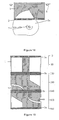
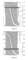
- Figures 15 and 16 show the surface of the first rotation element 1 of the fifth rotary engine. Figures 15 and 16 also show the relative positions of the second rotation elements 3a, 3b, 3c. In figure 16, the first rotation element 1 has rotated by 60° compared to figure 15. The hatched areas show the surfaces of the first rotation element 1 that define the cavity, and the second rotation elements 3a, 3b, 3c.
- Figure 17 shows the surface of the first rotation element 1 of a sixth rotary engine according to the invention.
- Figure 17 also shows the relative positions of the second rotation elements 3.
- the sixth rotary engine has six second rotation elements 3 performing the compression-combustion-expansion cycle in six working portions of the chamber.
- the provision of six second rotation elements 3 allows individual ones of them to be positioned on opposite sides of the first axis 6, thus balancing the forces generated during combustion. This minimises the net forces on the first rotation element 1, and ensures the centre of mass of first rotation element 1 lies on the first axis 6.
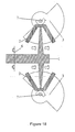
- Figure 18 shows a cross section of a seventh rotary engine according to the invention.
- the seventh rotary engine also has six second rotation elements 3 performing the compression-combustion-expansion cycle in six working portions of the chamber. Forces generated during combustion are balanced by positioning second rotation elements 3 on opposite sides of the first rotation element 1.
- FIGS 19 to 27 show cross sections of an eighth rotary engine according to the invention.
- the eighth rotary engine comprises a large number of second rotation elements 3 distributed around the casing 2.
- Each of the second rotation elements 3 includes two lobes of unequal length.
- the cross sectional area of the cavity varies gradually around the first axis 6.
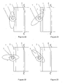
- Figures 20 to 27 show the eighth rotary engine at various stages of the compression-combustion-expansion process.
- the second rotation element 3 has rotated to a position where it does not project into the first rotation element 1.
- a seal is formed between the first rotation element 1 and the casing 2. This seal defines the two ends of the cavity that extends around the first axis 6 and ensures that fresh gases drawn in to the cavity do not mix with exhausted gases.
- the first rotation element 1 has rotated in to the cavity defined between the first rotation element 1 and the casing 2.
- a working portion of the cavity is now defined between the seal formed by the first rotation element 1 and the casing 2, and the second rotation element 3. Gases are drawn into the working portion of the cavity as it expands through a fluid inlet passage 4, as indicated by the arrow.
- the engine continues to rotate and gases are drawn into the cavity until it the second rotation element 3 has rotated into the position shown in figure 22. In this position, the working portion of the cavity is defined between adjacent second rotation elements 3.
- the fluid inlet passage 4 has rotated away from the working portion of the cavity, which is now fully enclosed.
- the working portion of the cavity continues to contract until the second rotation element 3 reaches the position shown in figure 24. In this position, the volume of the working portion of the cavity is at a minimum and the gases contained therein have been compressed. Combustion of the gases is then induced, thus causing a further increase in the pressure of the gases.
- each of the second rotation elements 3 include two lobes of different shape. One of the lobes is used during compression and the other is used during expansion.
- the engine continues to rotate so that the exhausted gases are expelled, as shown in figure 27.
- the second rotation element 3 has rotated further so that the working portion of the cavity is contracting.
- the first rotation element 1 has also rotated so that a fluid outlet channel is exposed to the working portion of the cavity. As the working portion of the cavity contracts, the gases contained therein are expelled from the engine through the fluid outlet passage 9, thus completing a cycle of the rotary engine.
- Figures 28 to 30 show a ninth rotary engine according to the invention.
- the ninth rotary engine utilises sliding valves 10 to control its compression ratio.
- the sliding valves 10 are located in a region of the casing surface that defines the working portion of the cavity during compression of the gases, but not during expansion of the gases. This is achieved by ensuring that the segment of each of the second rotation elements that co-operates with the compression segment of the first rotation element 1 has the largest radius.
- the fluid outlet passage 9 is provided within the first rotation element 1, as shown in figure 29.
- the ninth rotary engine is different to other rotary engines according to the invention, for example the fifth engine shown in figure 11.
- the design of the first rotation element 1, as shown in figure 29, allows gases to flow between working portions of the cavity defined on opposite sides of the second rotation element 3a during expulsion, thus providing an exit route for the gases as the working portion of the cavity contracts.
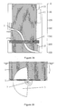
- Figure 30 shows the surface of the first rotation element 1 of the ninth rotary engine, together with an indication of the relative positions of the second rotation elements 3a, 3b, 3c and the sliding valves 10.
- Each of the valves 10 has a sliding cover 11.
- Figure 30 shows the position of the sliding covers when the sliding valves 10 are fully open.
- the sliding valves 10 allow the compression-combustion-expansion cycle of the engine to be modified.
- the cycle can be modified so that the some of the compressed gases are vented from the working portion of the cavity prior to combustion, thus reducing the compression ratio of the engine.
- the vented gases will be recycled so as to reduce fuel inefficiency.
- the pressure of the gases, and thus the compression ratio of the engine can be controlled. In this way, the sliding valves 10 can be used to control the power output of the engine.
- the sliding valves 10 are only in use during compression of the gases. Therefore, the sliding valves 10 may remain in the same position throughout the compression-combustion-expansion cycle.
- the positions of the sliding valves 10 are only modified if a change in the compression ratio of the engine is desired. This principal of operation differs from a conventional combustion engine, in which the valves open and close in every compression-combustion-expansion cycle.
- Valves may form the exclusive fluid inlet for the rotary engine, or else may be provided in combination with one or more fluid inlet passages in the first rotation element 1. Where valves form a fluid inlet to the rotary engine, they may be used to adjust the timing at which gases are no longer drawn into the engine.
- Figures 31 to 33 show a first compressor.
- the first compressor operates in a similar way to the rotary engines according to the invention described above. However, the elimination of combustion and expansion stages from the operating cycle allows simplification.
- the compressor comprises a single second rotation element 3 that rotates at half the angular velocity of the first rotation element 1. Gases are drawn into the compressor, compressed and then released through a sliding valve 10.
- the sliding valve 10 can be used to control the extent to which the gases are compressed by the compressor.
- the first rotation element 1 may be designed so that, during release of the compressed gases, gases may flow between working portions of the cavity defined on opposite sides of the second rotation element 3. This provides an exit route for the gases as the working portion of the cavity contracts.
- the compressor may comprise two second rotation elements in order to balance the forces on the first rotation element 1. This may be achieved using the techniques disclosed in figures 17 and 18 and the descriptions thereof.
- Figure 34 shows a second compressor. In this compressor, the volume of the working portion of the cavity is larger than in the first compressor.
- Figures 35 and 36 show a third compressor.
- sliding valves 10 are used to control the intake of gases rather than their expulsion.
- the first, second, and third compressors may operate as expanders. In this case, compressed gases are fed into the fluid outlet and the first and second rotation elements are driven in the opposite directions to those shown in the figures.
- Figure 37 shows a cross section of a tenth rotary engine according to the invention.
- a number of small teeth 12 have been added to the second rotation elements 3.
- the first rotation element 1 may directly drive the second rotation elements 3 at the correct angular velocity.
- the small teeth 12 and the parts of the first rotation element 1 with which they mesh shall have rounded corners.
- Figures 38 and 39 show cross sections of eleventh and twelfth rotary engines according to the invention respectively.
- the eleventh rotary engine comprises second rotation elements 3 whose centre of gravity is on their axis of rotation. This provides for ease of manufacture and is achieved by providing twice as many segments as are provided in the second rotation elements of the other described rotary inventions.
- the segments of the second rotation elements 3 span smaller angles than in the other described rotary engines, and thus the cavities volumes of the working portions of the cavity that they define are smaller. However, to some extent this is compensated in the eleventh rotary engine by having cavities on either side of the second rotation element 3. In this way, the eleventh rotary engine may operate as a composite engine.
- the two cavities are positioned out of phase, thus producing a smoother power output.
- Excess material has also been removed from the first rotation element 1 of the twelfth rotary engine. This minimises engine weight, minimises the contact area between the first rotation element 1 and the casing 2, and provides enhanced ventilation for the engine.
- the shape of the second rotation elements corresponds to the cross sectional shape of the cavity. Since force is proportional to a pressure difference multiplied by area, careful design of the shape of the second rotation elements may provide an engine having a power output that is constant over an entire revolution. For an engine having a single cavity, the area of the first rotation element on which work is performed is the difference between the area of second rotation elements that define each end of the cavity. The volume and thus pressure of gases within a cavity may be calculated. This pressure and volume allow calculation of the available energy as a function of the rotation of the first rotation element, thus allowing calculation of the torque of the engine.
- the torque from each cavity may be found.
- a shape for the second rotation elements may then be found that provides an engine having a smooth torque output.
- the shape of the second rotation elements may be specified by radius as a function of the angle. Specifying a goal such as "maximise the minimum torque" allows computational methods that will be known to those skilled in the art to be used to find a shape of second rotation element that provides an engine having a smooth power output.
- Figure 40 shows an example of a shape of second rotation element 3 that may be used to provide an engine having smooth power output.
- the spike at the top left of the second rotation element 3a reduces the area that performs compression-of the gases-when pressure is high.
- the spike at the bottom right of the second rotation element 3a allows a gradual expansion of gases when the pressure is high, and a rapid expansion of gases when the pressure is lower, thus providing an engine having a steady power output.
- Figure 41 shows a cross section of a fourteenth rotary engine according to the invention.
- the fourteenth rotary engine has an annular first rotation element 1 that is mounted external to the casing 2.
- Two second rotation elements 3a, 3b are mounted within the casing 2.
- these elements have been mounted so that the plane of the second rotation elements does not intersect the axis of the first rotation element. This allows the second rotation elements to have a maximum radius greater than the inner radius of the casing, allowing a larger working volume for a given engine radius.
- this engine has a relatively low casing radius compared to the outer radius of the first rotation element. This gives a relatively low area for friction between the first rotation element and the casing, and a relatively small length for leakage between the casing and the first rotation element.
- Figures 42 to 46 illustrate some of the characteristics of the device according to the invention that distinguish it from known rotary devices. It is noted that the parts shown in these figures have already been described with reference to earlier figures, and that figures 42 to 46 do not add additional knowledge required for building the engine or understanding its operation.
- Figures 42 to 44 illustrate second rotation elements 3 that may be viewed as having one large tooth.
- Figure 45 illustrates a second rotation element that may be viewed as having two large teeth.
- the teeth are the parts of the second rotation element that protrude into the cavity defined by the casing and the first rotation element at some part of the cycle.
- the teeth define a "tooth-angle", ⁇ , measured around the axis of the rotation element 3.
- the second rotation element is designed so that the tooth angle is just less than 360°/t, where t is the number of teeth.
- the tooth-angle ⁇ is just under 360°, and the single tooth comprises three integral segments, or projecting portions.
- the tooth-angle is just under 180°, and each tooth comprises three integral segments, or projecting portions.
- Figure 46 illustrates that the casing 2 may be viewed as having a slot-angle, ⁇ , measured around the axis of the first rotation element 3, and defined by the region where the second rotation element may project into the cavity.
- the tooth-angle ⁇ is larger than the slot angle ⁇ .
Landscapes
- Engineering & Computer Science (AREA)
- Mechanical Engineering (AREA)
- General Engineering & Computer Science (AREA)
- Fluid Mechanics (AREA)
- Physics & Mathematics (AREA)
- Applications Or Details Of Rotary Compressors (AREA)
- Supercharger (AREA)
- Output Control And Ontrol Of Special Type Engine (AREA)
- Hydraulic Motors (AREA)
- Rotary Pumps (AREA)
- Centrifugal Separators (AREA)
- Iron Core Of Rotating Electric Machines (AREA)
- Engine Equipment That Uses Special Cycles (AREA)
- Pharmaceuticals Containing Other Organic And Inorganic Compounds (AREA)
- Organic Low-Molecular-Weight Compounds And Preparation Thereof (AREA)
- Reciprocating Pumps (AREA)
Applications Claiming Priority (2)
| Application Number | Priority Date | Filing Date | Title |
|---|---|---|---|
| GB0314035A GB2402974A (en) | 2003-06-17 | 2003-06-17 | Rotary device in which rotor has sectors of different radii |
| PCT/GB2004/002483 WO2004113683A1 (en) | 2003-06-17 | 2004-06-15 | Rotary-piston machine |
Publications (2)
| Publication Number | Publication Date |
|---|---|
| EP1633956A1 EP1633956A1 (en) | 2006-03-15 |
| EP1633956B1 true EP1633956B1 (en) | 2007-08-15 |
Family
ID=27636721
Family Applications (1)
| Application Number | Title | Priority Date | Filing Date |
|---|---|---|---|
| EP04736841A Expired - Lifetime EP1633956B1 (en) | 2003-06-17 | 2004-06-15 | Rotary-piston machine |
Country Status (13)
| Country | Link |
|---|---|
| US (1) | US7650871B2 (https=) |
| EP (1) | EP1633956B1 (https=) |
| JP (1) | JP4489768B2 (https=) |
| KR (1) | KR101108106B1 (https=) |
| CN (1) | CN100478544C (https=) |
| AT (1) | ATE370313T1 (https=) |
| BR (1) | BRPI0411565B1 (https=) |
| CA (1) | CA2528017C (https=) |
| DE (1) | DE602004008269T2 (https=) |
| ES (1) | ES2293265T3 (https=) |
| GB (1) | GB2402974A (https=) |
| RU (1) | RU2346163C2 (https=) |
| WO (1) | WO2004113683A1 (https=) |
Families Citing this family (14)
| Publication number | Priority date | Publication date | Assignee | Title |
|---|---|---|---|---|
| US8365698B2 (en) | 2004-01-12 | 2013-02-05 | Liquidpiston, Inc. | Hybrid cycle combustion engine and methods |
| GB0603099D0 (en) | 2006-02-16 | 2006-03-29 | Lontra Environmental Technolog | Rotary piston and cylinder devices |
| EP2047065A2 (en) | 2006-08-02 | 2009-04-15 | Liquidpiston, Inc. | Hybrid cycle rotary engine |
| HU229249B1 (hu) * | 2007-10-03 | 2013-10-28 | Mester Gabor | Térfogatváltoztató forgó gép, elõnyösen kétütemû gömbmotor |
| US8863724B2 (en) | 2008-08-04 | 2014-10-21 | Liquidpiston, Inc. | Isochoric heat addition engines and methods |
| IT1401427B1 (it) * | 2010-08-11 | 2013-07-26 | Nuova Pignone S R L | Metodi e dispositivi usati per controllare automaticamente la velocita di un espansore |
| US9267504B2 (en) | 2010-08-30 | 2016-02-23 | Hicor Technologies, Inc. | Compressor with liquid injection cooling |
| CA2809945C (en) | 2010-08-30 | 2018-10-16 | Oscomp Systems Inc. | Compressor with liquid injection cooling |
| CA2830653C (en) | 2011-03-29 | 2019-11-05 | Liquidpiston, Inc. | Cycloid rotor engine |
| SG10201708784YA (en) | 2013-01-25 | 2017-12-28 | Liquidpiston Inc | Air-cooled rotary engine |
| RU2520774C1 (ru) * | 2013-05-14 | 2014-06-27 | Федеральное государственное бюджетное образовательное учреждение высшего профессионального образования "Омский государственный технический университет" | Роторный насос объемного действия |
| CN104675438A (zh) * | 2014-01-22 | 2015-06-03 | 摩尔动力(北京)技术股份有限公司 | 径向多级流体机构及包括其的装置 |
| CN104727934A (zh) * | 2014-02-02 | 2015-06-24 | 摩尔动力(北京)技术股份有限公司 | 径向多级防窜流流体机构及包括其的装置 |
| CN109505659A (zh) * | 2018-05-15 | 2019-03-22 | 万常玉 | 气体膨胀压力动力机 |
Family Cites Families (53)
| Publication number | Priority date | Publication date | Assignee | Title |
|---|---|---|---|---|
| US1305133A (en) * | 1919-05-27 | Rotary engine or pump | ||
| US889439A (en) * | 1907-09-07 | 1908-06-02 | Thomas Collins | Rotary engine. |
| US1012616A (en) * | 1911-05-20 | 1911-12-26 | George M Appell | Rotary engine. |
| US1106666A (en) * | 1912-09-19 | 1914-08-11 | William O Miller | Rotary internal-combustion engine. |
| DE320038C (de) * | 1918-01-26 | 1920-05-21 | Emil Ludwig | Drehkolbenpumpe mit Globoidschnecke und darin eingreifender Zahnscheibe |
| GB653185A (en) | 1948-05-19 | 1951-05-09 | James Wallis Goodyear | Improvements in or relating to rotary engines, pumps and the like |
| US2674982A (en) * | 1951-09-14 | 1954-04-13 | William B Mccall | Internal-combustion engine |
| US3012551A (en) * | 1960-02-24 | 1961-12-12 | John P Renshaw | Rotary engine |
| US3060910A (en) * | 1960-11-21 | 1962-10-30 | William B Mccall | Rotary internal combustion engine |
| US3214907A (en) * | 1961-04-19 | 1965-11-02 | Martin Erich | Multi-stage engine and method for operating the engine by combustion |
| US3221717A (en) * | 1961-07-10 | 1965-12-07 | John P Renshaw | Positive displacement energy converting device |
| US3205874A (en) * | 1962-01-17 | 1965-09-14 | John P Renshaw | Rotary type positive displacement energy converting device |
| US3208437A (en) * | 1962-04-02 | 1965-09-28 | George M Coulter | Internal combustion engine |
| FR1370790A (fr) * | 1963-07-17 | 1964-08-28 | Dispositif rotatif à équipages mobiles pour comprimer, détendre ou entraîner un fluide | |
| US3502054A (en) * | 1967-12-04 | 1970-03-24 | K M F Dev Corp | Internal-combustion engine |
| FR1601531A (https=) * | 1968-12-27 | 1970-08-24 | ||
| FR1600666A (https=) * | 1968-12-31 | 1970-07-27 | ||
| US3739754A (en) * | 1970-12-03 | 1973-06-19 | A Nutku | Rotating-piston toroidal machine with rotating-disc abutment |
| JPS5025085B1 (https=) * | 1970-12-16 | 1975-08-21 | ||
| US3726616A (en) * | 1971-01-11 | 1973-04-10 | Univ Northwestern | Fluid actuated energy translating device |
| US3897756A (en) * | 1973-07-09 | 1975-08-05 | Lewis E Upchurch | Tandem rotor rotary engine |
| US3862623A (en) * | 1973-11-19 | 1975-01-28 | Clarence W Ehlert | Rotary engine |
| US4558669A (en) | 1975-01-27 | 1985-12-17 | Vida M. Kemp | Ignition apparatus for a rotary internal combustion engine |
| US4013046A (en) * | 1975-01-27 | 1977-03-22 | Kemp Gail W | Rotary engine |
| US4005682A (en) * | 1975-05-08 | 1977-02-01 | Mccall William B | Rotary internal combustion engine |
| JPS5487911A (en) * | 1977-12-26 | 1979-07-12 | Hitachi Ltd | Capacity type compressor |
| DE2827211A1 (de) * | 1978-06-21 | 1980-01-10 | Guenther Niessen | Motor |
| DE3041606A1 (de) * | 1980-10-31 | 1982-06-09 | Kurt 1000 Berlin Grzanna | Motor zur nutzung der expansionsarbeit von komprimiertem gas |
| FR2531744A1 (fr) * | 1982-08-12 | 1984-02-17 | Rousseau Gerard | Turbine a pales croisees |
| DE3301726A1 (de) * | 1983-01-20 | 1984-07-26 | Peter Graf von 8000 München Ingelheim | Waermekraftmaschinen mit kontinuierlicher oder intermittierender waermezufuehrung und durch sie moegliche verbesserungen thermodynamischer kreisprozesse bei waerme- und krafterzeugung |
| JPS63295818A (ja) * | 1987-05-26 | 1988-12-02 | Nobuyuki Tanaka | ロ−タリエンジン |
| JPS63227901A (ja) * | 1987-10-22 | 1988-09-22 | Rokurou Kagamiyama | ロータリピストン式流体機械 |
| JPH03100328A (ja) * | 1989-09-11 | 1991-04-25 | Tetsuo Makita | 環状回転式シリンダーエンジン |
| JPH04101021A (ja) * | 1990-08-13 | 1992-04-02 | Ishikawajima Harima Heavy Ind Co Ltd | ロータリーエンジン |
| DE4127870A1 (de) * | 1991-08-22 | 1992-01-16 | Josef Lipinski | Kraftmaschine, insbesondere brennkraftmaschine mit umlaufenden kolben als 2-scheiben-kreiskolbenmotor |
| CA2059757C (en) * | 1992-01-21 | 1994-04-12 | J. Robert Belanger | Rotary engine |
| DE4226063A1 (de) * | 1992-07-21 | 1994-01-27 | Bruch Claus Dieter | Verbrennungskraftmaschine |
| RU2044893C1 (ru) * | 1992-11-06 | 1995-09-27 | Юрий Михайлович Макушенко | Роторно-поршневая машина |
| DE4323345C2 (de) * | 1993-07-13 | 1996-04-11 | Wilhelm Talhoff | Drehkolben-Brennkraftmaschine |
| DE29522008U1 (de) * | 1995-01-19 | 1999-07-29 | Raab, Anton Gerhard, 80686 München | Kraftmaschine |
| DE19509913A1 (de) * | 1995-03-18 | 1996-09-19 | Juergen Walter | Umlaufkolbenmaschine |
| GB9509742D0 (en) * | 1995-05-13 | 1995-07-05 | Francis Shaw P L C | Internal mixers |
| FR2748775B1 (fr) * | 1996-05-14 | 1998-06-26 | Bouquet Henri | Moteur a explosion rotatif dont toutes les pieces mobiles decrivent des circonferences autour d'axes fixes dans un bloc-moteur d'usinage plus simple que celui des moteurs classiques "beau de rochas" |
| GB2333561B (en) * | 1998-01-21 | 2002-03-20 | John Edward Archer | Rotary machine |
| GB9801859D0 (en) * | 1998-01-30 | 1998-03-25 | Lindsey Stephen F | Rotary piston and cylinder devices |
| WO2000012867A1 (en) * | 1998-08-27 | 2000-03-09 | Milan Ondrich | Internal combustion engine |
| US6257195B1 (en) | 2000-02-14 | 2001-07-10 | Arthur Vanmoor | Internal combustion engine with substantially continuous fuel feed and power output |
| GB2356896A (en) * | 1999-11-30 | 2001-06-06 | Muhammad Yousuf Khalid | Internal combustion rotary engine |
| EP1307634B1 (en) * | 2000-08-04 | 2004-11-03 | VGT Technologies Inc. | Variable geometry toroidal engine |
| GB2374903A (en) * | 2001-04-27 | 2002-10-30 | Paolo Niccolai | An engine having a doughnut shaped cylinder |
| US6588395B2 (en) * | 2001-05-08 | 2003-07-08 | Defazio Robert | Rotary internal combustion engine—designed for future adiabatic operation |
| DE10354621A1 (de) * | 2003-08-02 | 2005-06-23 | Sauer, Christian | Kolbenmaschine |
| US7059294B2 (en) * | 2004-05-27 | 2006-06-13 | Wright Innovations, Llc | Orbital engine |
-
2003
- 2003-06-17 GB GB0314035A patent/GB2402974A/en not_active Withdrawn
-
2004
- 2004-06-15 CA CA2528017A patent/CA2528017C/en not_active Expired - Fee Related
- 2004-06-15 AT AT04736841T patent/ATE370313T1/de not_active IP Right Cessation
- 2004-06-15 RU RU2005138123/06A patent/RU2346163C2/ru not_active IP Right Cessation
- 2004-06-15 ES ES04736841T patent/ES2293265T3/es not_active Expired - Lifetime
- 2004-06-15 DE DE602004008269T patent/DE602004008269T2/de not_active Expired - Lifetime
- 2004-06-15 KR KR1020057023824A patent/KR101108106B1/ko not_active Expired - Fee Related
- 2004-06-15 US US10/561,369 patent/US7650871B2/en not_active Expired - Fee Related
- 2004-06-15 JP JP2006516398A patent/JP4489768B2/ja not_active Expired - Fee Related
- 2004-06-15 EP EP04736841A patent/EP1633956B1/en not_active Expired - Lifetime
- 2004-06-15 BR BRPI0411565-1A patent/BRPI0411565B1/pt not_active IP Right Cessation
- 2004-06-15 CN CNB2004800165367A patent/CN100478544C/zh not_active Expired - Fee Related
- 2004-06-15 WO PCT/GB2004/002483 patent/WO2004113683A1/en not_active Ceased
Non-Patent Citations (1)
| Title |
|---|
| None * |
Also Published As
| Publication number | Publication date |
|---|---|
| EP1633956A1 (en) | 2006-03-15 |
| JP2006527813A (ja) | 2006-12-07 |
| RU2005138123A (ru) | 2006-07-10 |
| RU2346163C2 (ru) | 2009-02-10 |
| CN100478544C (zh) | 2009-04-15 |
| JP4489768B2 (ja) | 2010-06-23 |
| BRPI0411565A (pt) | 2006-08-01 |
| ES2293265T3 (es) | 2008-03-16 |
| CN1829853A (zh) | 2006-09-06 |
| US20070175435A1 (en) | 2007-08-02 |
| US7650871B2 (en) | 2010-01-26 |
| KR20060025169A (ko) | 2006-03-20 |
| BRPI0411565B1 (pt) | 2014-09-16 |
| WO2004113683A1 (en) | 2004-12-29 |
| DE602004008269T2 (de) | 2007-12-20 |
| ATE370313T1 (de) | 2007-09-15 |
| GB0314035D0 (en) | 2003-07-23 |
| CA2528017C (en) | 2012-03-27 |
| DE602004008269D1 (de) | 2007-09-27 |
| CA2528017A1 (en) | 2004-12-29 |
| GB2402974A (en) | 2004-12-22 |
| KR101108106B1 (ko) | 2012-01-31 |
Similar Documents
| Publication | Publication Date | Title |
|---|---|---|
| EP1633956B1 (en) | Rotary-piston machine | |
| US4074957A (en) | Screw compressors | |
| US4224016A (en) | Rotary positive displacement machines | |
| CN1131374C (zh) | 旋转正排式膨胀机 | |
| US6926505B2 (en) | Rotary machine housing with radially mounted sliding vanes | |
| US3902829A (en) | Rotary power device | |
| US7305963B2 (en) | Blade-thru-slot combustion engine, compressor, pump and motor | |
| AU2001231501A1 (en) | Equipment with mutually interacting spiral teeth | |
| WO2001061151A1 (en) | Equipment with mutually interacting spiral teeth | |
| US6901904B1 (en) | Sealing intersecting vane machines | |
| US5375987A (en) | Rotary vane mechanical power system utilizing positive displacement | |
| KR101032262B1 (ko) | 회전식 연소 장치 | |
| Read et al. | Operational characteristics of internally geared positive displacement screw machines | |
| GB2438859A (en) | Toroidal fluid machine | |
| CA3139764A1 (en) | Cooled dry vacuum screw pump | |
| RU2150027C1 (ru) | Способ изменения объема рабочих камер в объемных машинах | |
| WO2006043024A1 (en) | Rotary device | |
| RU2754184C9 (ru) | Роторный двигатель внутреннего сгорания | |
| CN2407127Y (zh) | 凹槽双燃室回转发动机 | |
| Finger et al. | Design and analysis of a miniature rotary Wankel compressor | |
| US7866297B2 (en) | Rotary heat engine | |
| RU2176022C2 (ru) | Роторная машина | |
| Bozrov et al. | Force and energetic characteristics of a spiral air motor | |
| HU230082B1 (hu) | Forgódugattyús gép |
Legal Events
| Date | Code | Title | Description |
|---|---|---|---|
| PUAI | Public reference made under article 153(3) epc to a published international application that has entered the european phase |
Free format text: ORIGINAL CODE: 0009012 |
|
| 17P | Request for examination filed |
Effective date: 20051123 |
|
| AK | Designated contracting states |
Kind code of ref document: A1 Designated state(s): AT BE BG CH CY CZ DE DK EE ES FI FR GB GR HU IE IT LI LU MC NL PL PT RO SE SI SK TR |
|
| DAX | Request for extension of the european patent (deleted) | ||
| GRAP | Despatch of communication of intention to grant a patent |
Free format text: ORIGINAL CODE: EPIDOSNIGR1 |
|
| GRAS | Grant fee paid |
Free format text: ORIGINAL CODE: EPIDOSNIGR3 |
|
| GRAA | (expected) grant |
Free format text: ORIGINAL CODE: 0009210 |
|
| AK | Designated contracting states |
Kind code of ref document: B1 Designated state(s): AT BE BG CH CY CZ DE DK EE ES FI FR GB GR HU IE IT LI LU MC NL PL PT RO SE SI SK TR |
|
| REG | Reference to a national code |
Ref country code: GB Ref legal event code: FG4D |
|
| REG | Reference to a national code |
Ref country code: CH Ref legal event code: EP |
|
| REG | Reference to a national code |
Ref country code: IE Ref legal event code: FG4D |
|
| REF | Corresponds to: |
Ref document number: 602004008269 Country of ref document: DE Date of ref document: 20070927 Kind code of ref document: P |
|
| PG25 | Lapsed in a contracting state [announced via postgrant information from national office to epo] |
Ref country code: NL Free format text: LAPSE BECAUSE OF FAILURE TO SUBMIT A TRANSLATION OF THE DESCRIPTION OR TO PAY THE FEE WITHIN THE PRESCRIBED TIME-LIMIT Effective date: 20070815 Ref country code: BG Free format text: LAPSE BECAUSE OF FAILURE TO SUBMIT A TRANSLATION OF THE DESCRIPTION OR TO PAY THE FEE WITHIN THE PRESCRIBED TIME-LIMIT Effective date: 20071115 Ref country code: FI Free format text: LAPSE BECAUSE OF FAILURE TO SUBMIT A TRANSLATION OF THE DESCRIPTION OR TO PAY THE FEE WITHIN THE PRESCRIBED TIME-LIMIT Effective date: 20070815 |
|
| NLV1 | Nl: lapsed or annulled due to failure to fulfill the requirements of art. 29p and 29m of the patents act | ||
| ET | Fr: translation filed | ||
| PG25 | Lapsed in a contracting state [announced via postgrant information from national office to epo] |
Ref country code: AT Free format text: LAPSE BECAUSE OF FAILURE TO SUBMIT A TRANSLATION OF THE DESCRIPTION OR TO PAY THE FEE WITHIN THE PRESCRIBED TIME-LIMIT Effective date: 20070815 Ref country code: LI Free format text: LAPSE BECAUSE OF FAILURE TO SUBMIT A TRANSLATION OF THE DESCRIPTION OR TO PAY THE FEE WITHIN THE PRESCRIBED TIME-LIMIT Effective date: 20070815 Ref country code: CH Free format text: LAPSE BECAUSE OF FAILURE TO SUBMIT A TRANSLATION OF THE DESCRIPTION OR TO PAY THE FEE WITHIN THE PRESCRIBED TIME-LIMIT Effective date: 20070815 Ref country code: PL Free format text: LAPSE BECAUSE OF FAILURE TO SUBMIT A TRANSLATION OF THE DESCRIPTION OR TO PAY THE FEE WITHIN THE PRESCRIBED TIME-LIMIT Effective date: 20070815 |
|
| REG | Reference to a national code |
Ref country code: CH Ref legal event code: PL |
|
| REG | Reference to a national code |
Ref country code: ES Ref legal event code: FG2A Ref document number: 2293265 Country of ref document: ES Kind code of ref document: T3 |
|
| PG25 | Lapsed in a contracting state [announced via postgrant information from national office to epo] |
Ref country code: BE Free format text: LAPSE BECAUSE OF FAILURE TO SUBMIT A TRANSLATION OF THE DESCRIPTION OR TO PAY THE FEE WITHIN THE PRESCRIBED TIME-LIMIT Effective date: 20070815 |
|
| PG25 | Lapsed in a contracting state [announced via postgrant information from national office to epo] |
Ref country code: DK Free format text: LAPSE BECAUSE OF FAILURE TO SUBMIT A TRANSLATION OF THE DESCRIPTION OR TO PAY THE FEE WITHIN THE PRESCRIBED TIME-LIMIT Effective date: 20070815 Ref country code: GR Free format text: LAPSE BECAUSE OF FAILURE TO SUBMIT A TRANSLATION OF THE DESCRIPTION OR TO PAY THE FEE WITHIN THE PRESCRIBED TIME-LIMIT Effective date: 20071116 |
|
| PG25 | Lapsed in a contracting state [announced via postgrant information from national office to epo] |
Ref country code: PT Free format text: LAPSE BECAUSE OF FAILURE TO SUBMIT A TRANSLATION OF THE DESCRIPTION OR TO PAY THE FEE WITHIN THE PRESCRIBED TIME-LIMIT Effective date: 20080115 Ref country code: SK Free format text: LAPSE BECAUSE OF FAILURE TO SUBMIT A TRANSLATION OF THE DESCRIPTION OR TO PAY THE FEE WITHIN THE PRESCRIBED TIME-LIMIT Effective date: 20070815 Ref country code: CZ Free format text: LAPSE BECAUSE OF FAILURE TO SUBMIT A TRANSLATION OF THE DESCRIPTION OR TO PAY THE FEE WITHIN THE PRESCRIBED TIME-LIMIT Effective date: 20070815 |
|
| PLBE | No opposition filed within time limit |
Free format text: ORIGINAL CODE: 0009261 |
|
| STAA | Information on the status of an ep patent application or granted ep patent |
Free format text: STATUS: NO OPPOSITION FILED WITHIN TIME LIMIT |
|
| PG25 | Lapsed in a contracting state [announced via postgrant information from national office to epo] |
Ref country code: RO Free format text: LAPSE BECAUSE OF FAILURE TO SUBMIT A TRANSLATION OF THE DESCRIPTION OR TO PAY THE FEE WITHIN THE PRESCRIBED TIME-LIMIT Effective date: 20070815 Ref country code: SE Free format text: LAPSE BECAUSE OF FAILURE TO SUBMIT A TRANSLATION OF THE DESCRIPTION OR TO PAY THE FEE WITHIN THE PRESCRIBED TIME-LIMIT Effective date: 20071115 |
|
| 26N | No opposition filed |
Effective date: 20080516 |
|
| PG25 | Lapsed in a contracting state [announced via postgrant information from national office to epo] |
Ref country code: MC Free format text: LAPSE BECAUSE OF NON-PAYMENT OF DUE FEES Effective date: 20080630 |
|
| PG25 | Lapsed in a contracting state [announced via postgrant information from national office to epo] |
Ref country code: EE Free format text: LAPSE BECAUSE OF FAILURE TO SUBMIT A TRANSLATION OF THE DESCRIPTION OR TO PAY THE FEE WITHIN THE PRESCRIBED TIME-LIMIT Effective date: 20070815 |
|
| PG25 | Lapsed in a contracting state [announced via postgrant information from national office to epo] |
Ref country code: SI Free format text: LAPSE BECAUSE OF FAILURE TO SUBMIT A TRANSLATION OF THE DESCRIPTION OR TO PAY THE FEE WITHIN THE PRESCRIBED TIME-LIMIT Effective date: 20070815 |
|
| PG25 | Lapsed in a contracting state [announced via postgrant information from national office to epo] |
Ref country code: CY Free format text: LAPSE BECAUSE OF FAILURE TO SUBMIT A TRANSLATION OF THE DESCRIPTION OR TO PAY THE FEE WITHIN THE PRESCRIBED TIME-LIMIT Effective date: 20070815 |
|
| PG25 | Lapsed in a contracting state [announced via postgrant information from national office to epo] |
Ref country code: LU Free format text: LAPSE BECAUSE OF NON-PAYMENT OF DUE FEES Effective date: 20080615 Ref country code: HU Free format text: LAPSE BECAUSE OF FAILURE TO SUBMIT A TRANSLATION OF THE DESCRIPTION OR TO PAY THE FEE WITHIN THE PRESCRIBED TIME-LIMIT Effective date: 20080216 |
|
| PG25 | Lapsed in a contracting state [announced via postgrant information from national office to epo] |
Ref country code: TR Free format text: LAPSE BECAUSE OF FAILURE TO SUBMIT A TRANSLATION OF THE DESCRIPTION OR TO PAY THE FEE WITHIN THE PRESCRIBED TIME-LIMIT Effective date: 20070815 |
|
| REG | Reference to a national code |
Ref country code: FR Ref legal event code: PLFP Year of fee payment: 12 |
|
| PGFP | Annual fee paid to national office [announced via postgrant information from national office to epo] |
Ref country code: IT Payment date: 20150625 Year of fee payment: 12 |
|
| REG | Reference to a national code |
Ref country code: FR Ref legal event code: PLFP Year of fee payment: 13 |
|
| PG25 | Lapsed in a contracting state [announced via postgrant information from national office to epo] |
Ref country code: IT Free format text: LAPSE BECAUSE OF NON-PAYMENT OF DUE FEES Effective date: 20150615 |
|
| PGFP | Annual fee paid to national office [announced via postgrant information from national office to epo] |
Ref country code: IE Payment date: 20160609 Year of fee payment: 13 Ref country code: GB Payment date: 20160615 Year of fee payment: 13 Ref country code: DE Payment date: 20160607 Year of fee payment: 13 Ref country code: ES Payment date: 20160613 Year of fee payment: 13 |
|
| PGFP | Annual fee paid to national office [announced via postgrant information from national office to epo] |
Ref country code: FR Payment date: 20160613 Year of fee payment: 13 |
|
| REG | Reference to a national code |
Ref country code: DE Ref legal event code: R119 Ref document number: 602004008269 Country of ref document: DE |
|
| GBPC | Gb: european patent ceased through non-payment of renewal fee |
Effective date: 20170615 |
|
| REG | Reference to a national code |
Ref country code: IE Ref legal event code: MM4A |
|
| REG | Reference to a national code |
Ref country code: FR Ref legal event code: ST Effective date: 20180228 |
|
| PG25 | Lapsed in a contracting state [announced via postgrant information from national office to epo] |
Ref country code: DE Free format text: LAPSE BECAUSE OF NON-PAYMENT OF DUE FEES Effective date: 20180103 Ref country code: GB Free format text: LAPSE BECAUSE OF NON-PAYMENT OF DUE FEES Effective date: 20170615 Ref country code: IE Free format text: LAPSE BECAUSE OF NON-PAYMENT OF DUE FEES Effective date: 20170615 |
|
| PG25 | Lapsed in a contracting state [announced via postgrant information from national office to epo] |
Ref country code: FR Free format text: LAPSE BECAUSE OF NON-PAYMENT OF DUE FEES Effective date: 20170630 |
|
| REG | Reference to a national code |
Ref country code: ES Ref legal event code: FD2A Effective date: 20181113 |
|
| PG25 | Lapsed in a contracting state [announced via postgrant information from national office to epo] |
Ref country code: ES Free format text: LAPSE BECAUSE OF NON-PAYMENT OF DUE FEES Effective date: 20170616 |