EP1633849B1 - Verfahren und vorrichtung zur schnellen bestimmung einer bakteriellen belastung in blut und blutprodukten - Google Patents
Verfahren und vorrichtung zur schnellen bestimmung einer bakteriellen belastung in blut und blutprodukten Download PDFInfo
- Publication number
- EP1633849B1 EP1633849B1 EP04730852A EP04730852A EP1633849B1 EP 1633849 B1 EP1633849 B1 EP 1633849B1 EP 04730852 A EP04730852 A EP 04730852A EP 04730852 A EP04730852 A EP 04730852A EP 1633849 B1 EP1633849 B1 EP 1633849B1
- Authority
- EP
- European Patent Office
- Prior art keywords
- impedance
- liquid sample
- sample
- frequencies
- processor
- Prior art date
- Legal status (The legal status is an assumption and is not a legal conclusion. Google has not performed a legal analysis and makes no representation as to the accuracy of the status listed.)
- Expired - Lifetime
Links
- 238000000034 method Methods 0.000 title claims abstract description 23
- 239000010836 blood and blood product Substances 0.000 title description 25
- 230000001580 bacterial effect Effects 0.000 title description 21
- 239000007788 liquid Substances 0.000 claims abstract description 49
- 244000005700 microbiome Species 0.000 claims abstract description 24
- 239000003990 capacitor Substances 0.000 claims description 31
- 238000005259 measurement Methods 0.000 claims description 8
- 239000000523 sample Substances 0.000 abstract description 76
- 229940125691 blood product Drugs 0.000 description 23
- 238000012360 testing method Methods 0.000 description 9
- 239000012530 fluid Substances 0.000 description 8
- 239000008267 milk Substances 0.000 description 8
- 210000004080 milk Anatomy 0.000 description 8
- 235000013336 milk Nutrition 0.000 description 8
- 238000012544 monitoring process Methods 0.000 description 8
- 238000010586 diagram Methods 0.000 description 7
- 238000002847 impedance measurement Methods 0.000 description 7
- 241000894006 Bacteria Species 0.000 description 6
- 238000001566 impedance spectroscopy Methods 0.000 description 6
- 230000000813 microbial effect Effects 0.000 description 6
- 238000011534 incubation Methods 0.000 description 5
- 238000004458 analytical method Methods 0.000 description 4
- 238000001514 detection method Methods 0.000 description 4
- 240000004808 Saccharomyces cerevisiae Species 0.000 description 3
- 235000014680 Saccharomyces cerevisiae Nutrition 0.000 description 3
- 230000035945 sensitivity Effects 0.000 description 3
- LFQSCWFLJHTTHZ-UHFFFAOYSA-N Ethanol Chemical compound CCO LFQSCWFLJHTTHZ-UHFFFAOYSA-N 0.000 description 2
- 210000004369 blood Anatomy 0.000 description 2
- 239000008280 blood Substances 0.000 description 2
- 238000013461 design Methods 0.000 description 2
- 238000011156 evaluation Methods 0.000 description 2
- 238000013213 extrapolation Methods 0.000 description 2
- 239000002609 medium Substances 0.000 description 2
- 230000010287 polarization Effects 0.000 description 2
- 239000011343 solid material Substances 0.000 description 2
- 101100390736 Danio rerio fign gene Proteins 0.000 description 1
- 101100390738 Mus musculus Fign gene Proteins 0.000 description 1
- 238000013459 approach Methods 0.000 description 1
- 238000003556 assay Methods 0.000 description 1
- 230000037358 bacterial metabolism Effects 0.000 description 1
- 238000010241 blood sampling Methods 0.000 description 1
- 238000004364 calculation method Methods 0.000 description 1
- 239000012141 concentrate Substances 0.000 description 1
- 238000011109 contamination Methods 0.000 description 1
- 238000012258 culturing Methods 0.000 description 1
- 230000007423 decrease Effects 0.000 description 1
- 230000003247 decreasing effect Effects 0.000 description 1
- 230000001419 dependent effect Effects 0.000 description 1
- 238000011161 development Methods 0.000 description 1
- 230000018109 developmental process Effects 0.000 description 1
- 230000000694 effects Effects 0.000 description 1
- 210000003743 erythrocyte Anatomy 0.000 description 1
- 210000003714 granulocyte Anatomy 0.000 description 1
- 239000001963 growth medium Substances 0.000 description 1
- 230000002503 metabolic effect Effects 0.000 description 1
- 230000004060 metabolic process Effects 0.000 description 1
- 230000002906 microbiologic effect Effects 0.000 description 1
- 238000004611 spectroscopical analysis Methods 0.000 description 1
- 239000000126 substance Substances 0.000 description 1
- 239000000758 substrate Substances 0.000 description 1
Images


Classifications
-
- G—PHYSICS
- G01—MEASURING; TESTING
- G01N—INVESTIGATING OR ANALYSING MATERIALS BY DETERMINING THEIR CHEMICAL OR PHYSICAL PROPERTIES
- G01N15/00—Investigating characteristics of particles; Investigating permeability, pore-volume or surface-area of porous materials
- G01N15/10—Investigating individual particles
- G01N15/1031—Investigating individual particles by measuring electrical or magnetic effects
-
- G—PHYSICS
- G01—MEASURING; TESTING
- G01N—INVESTIGATING OR ANALYSING MATERIALS BY DETERMINING THEIR CHEMICAL OR PHYSICAL PROPERTIES
- G01N15/00—Investigating characteristics of particles; Investigating permeability, pore-volume or surface-area of porous materials
- G01N15/10—Investigating individual particles
- G01N15/1031—Investigating individual particles by measuring electrical or magnetic effects
- G01N15/12—Investigating individual particles by measuring electrical or magnetic effects by observing changes in resistance or impedance across apertures when traversed by individual particles, e.g. by using the Coulter principle
-
- G—PHYSICS
- G01—MEASURING; TESTING
- G01N—INVESTIGATING OR ANALYSING MATERIALS BY DETERMINING THEIR CHEMICAL OR PHYSICAL PROPERTIES
- G01N27/00—Investigating or analysing materials by the use of electric, electrochemical, or magnetic means
- G01N27/02—Investigating or analysing materials by the use of electric, electrochemical, or magnetic means by investigating impedance
-
- G—PHYSICS
- G01—MEASURING; TESTING
- G01N—INVESTIGATING OR ANALYSING MATERIALS BY DETERMINING THEIR CHEMICAL OR PHYSICAL PROPERTIES
- G01N33/00—Investigating or analysing materials by specific methods not covered by groups G01N1/00 - G01N31/00
- G01N33/48—Biological material, e.g. blood, urine; Haemocytometers
- G01N33/483—Physical analysis of biological material
- G01N33/487—Physical analysis of biological material of liquid biological material
- G01N33/48707—Physical analysis of biological material of liquid biological material by electrical means
- G01N33/48735—Investigating suspensions of cells, e.g. measuring microbe concentration
-
- G—PHYSICS
- G01—MEASURING; TESTING
- G01N—INVESTIGATING OR ANALYSING MATERIALS BY DETERMINING THEIR CHEMICAL OR PHYSICAL PROPERTIES
- G01N15/00—Investigating characteristics of particles; Investigating permeability, pore-volume or surface-area of porous materials
- G01N15/10—Investigating individual particles
- G01N2015/1024—Counting particles by non-optical means
Definitions
- the present invention generally relates to a method and apparatus for monitoring microbial populations, and more particularly relates to a method and apparatus for fast non-invasive testing of liquid samples such as blood and blood products.
- blood products e.g. Erythrocytes, platelets (platelets), granulocytes or their respective concentrates and plasma and plasma derivatives or whole blood into consideration.
- Devices for determining the microorganism population in a sample are well known in the art. Using approximations of the growth rate of known bacterial populations, respective current populations are extrapolated into the past. For example, during growth of bacteria in a sample, impedance measurements are made on the sample. As the bacterial population in the sample grows and undergoes metabolism, the ion concentration of the sample changes and the electrical properties of the sample, in particular its, change Impedance. By measuring the impedance changes at constant temperature, the number of microorganisms can be estimated.
- a general approach to determining the bacterial population of liquid samples, particularly milk samples and blood product units, is based on a measurement of the impedance across the sample. As the impedance of a sample generally decreases with increasing bacterial population, impedance measurements across the sample provide a basis for estimating the bacterial population in the sample.
- electrodes in the sample are generally fed an AC voltage rather than a DC voltage after a DC voltage tends to cause rapid, insulating polarization at the interface between the liquid and the electrodes.
- a high-frequency AC voltage typically 1 kHz or more is used, the effect of such polarization on the measured impedances is greatly reduced.
- Existing devices for counting microorganisms typically use an AC voltage of 1 kHz or 10 kHz.
- a disadvantage of many bacterial growth assays is that they are invasive and inaccurate and require long incubation times to achieve reasonable results. This is mainly due to the fact that significant changes in impedance, typically a few per cent, appear only after long incubation times when very high bacteria concentrations, typically from 10 6 bacteria per cm 3 is reached.
- existing test equipment is extremely sensitive to temperature changes in the sample, which affects both the growth rate of the bacterial population and, more importantly, the magnitude of the measured impedances.
- a high detection threshold is required even if the temperature is severe is stabilized.
- a method for detecting bacteria in a wine tasting by measuring the impedance of the sample is PA Henschke & D. Susan Thomas "Detection of Wine Spoiling Jeasts by Electronic Methods", Journal of Applied Bacteriology 1988, Vol. 64, pp. 123-133 described.
- This article suggests the use of a chamber containing a sterilized medium as a reference to the tested wine sample. The reference to the sterilized medium compensates for changes in the impedance of the wine tasting Reason for physical and chemical factors that are not related to microbial growth. To distinguish between wine yeasts and foreign yeasts, this article looks at the possibility of delaying microbial growth in the wine yeasts using ethanol.
- Devices for monitoring bacteria adapted to receive a plurality of liquid samples, each sample provided with a pair of electrodes for passing current, are known. Such devices, which are typically referred to as multi-sensor impedance measuring devices, are useful for the simultaneous invasive monitoring of a plurality of liquid samples. Examples of such multi-samplers are described in U.S. Patent Nos. 3,890,201 and 4,072,578.
- the devices of U.S. Patent Nos. 3,890,201 and 4,072578 have a plurality of individual chambers for receiving a respective plurality of separate inoculated samples.
- the in the U.S. Patent No. 4,072,578 The apparatus described also includes a computerized means for controlling the analysis of bacterial growth in the separate compartments.
- a multichamber test device based on the principles described above is available from Malthus Instruments Ltd., England, under the trade name Malthus 2000 Microbiology System. This device measures the conductivity of up to 240 separate samples by applying a 10 kHz AC voltage across electrodes assigned to the samples. The microbial growth in each sample is assessed by measuring changes in the conductivity of a base containing metabolic CO 2 absorbed, detected using a computerized microbiological analyzer.
- EP0803728 describes a non-invasive impedance measurement for monitoring microbial growth.
- the article by Gómez describes an invasive measurement that involves the calculation of a Warburg impedance.
- the object of the present invention is to provide a substantially improved apparatus and method for monitoring the microbial population in a sample using impedance analysis.
- the method and apparatus of the present invention requires shorter monitoring and brooding times than prior art methods and apparatus.
- the present apparatus and method enables a more accurate measurement of extremely small populations of microorganisms.
- the method and the device are particularly suitable for the non-invasive testing of liquid samples in tubular or hose-like lines, such as in inlets and outlets of containers.
- Another embodiment is particularly suitable for non-invasive testing of blood product units, such as platelet units, preferably in the form of pouches.
- the present invention is based on the basic idea of the measured impedances by a suitable Circuit arrangement into predefined real and / or imaginary, ie complex components to disassemble. It has been found that some of these components are more sensitive to changes in the bacterial population in the sample than the total impedance of the sample. It therefore proves advantageous to analyze the bacterial population in the sample on the basis of the more reactive component.
- the element contains a warburg impedance.
- the liquid sample may be incubated for a preselected period of time prior to the measurement of the impedance.
- a corresponding device for evaluating the microorganism population in a fluid sample comprises a container suitable for receiving the fluid sample and an impedance processor which applies an AC voltage at a plurality of frequencies over at least a portion of the fluid sample and the impedance across at least the portion of the fluid sample in response to at least measuring some of the alternating frequencies, the impedance processor having circuitry for calculating a Warburg impedance of the sample based on the impedance measured over at least the portion and for evaluating the microorganism population in the sample based on the at least one calculated element.
- the impedance processor is electrically connected to the fluid sample in a non-invasive manner.
- the impedance processor has two capacitor plates for electrically noninvasively connecting the impedance processor to the fluid sample.
- the fluid sample has a plurality of sides, and both of the two capacitor plates are operatively connected to one of the plurality of sides.
- the above-mentioned device comprises a base plate, and the base plate and the two capacitor plates are substantially coplanar with each other, wherein the base plate surrounds and separates the two capacitor plates.
- a corresponding capacitive sensor for use in measuring the impedance of a fluid sample comprises two capacitor plates and a base plate, wherein the base plate and the two capacitor plates are substantially coplanar with each other and wherein the base plate surrounds and separates the two capacitor plates.
- the capacitive sensor may be permanently attached to the blood sampling unit.
- a corresponding liquid sample holder for use in measuring the impedance of a liquid sample comprises a container for holding the liquid sample and a capacitive sensor having two capacitor plates and a base plate, wherein the base plate and the two capacitor plates are substantially coplanar and wherein the base plate surrounds the two capacitor plates and separates.
- the above-mentioned designs are particularly suitable for use on a blood product unit in bag form.
- the liquid sample may comprise a platelet unit.
- the frequencies can be between 10 Hz and 10 MHz.
- the above-mentioned method is applied, for example, to the determination of the population of microorganisms in a liquid sample contained in a tubular or tubular member.
- a device adapted for this application for determining the microorganism population in a liquid sample comprises a tubular or tubular component for receiving or conducting the liquid sample therein; and an impedance processor that applies an alternating frequency at a plurality of frequencies over at least a portion of the liquid sample and measures the impedance over at least the portion of the liquid sample in response to at least some of the alternating frequencies, wherein the impedance processor comprises a plurality of circuitry for calculating at least one element of an electrical equivalent circuit of the sample based on the impedances measured over at least the portion and for determining the microorganism population in the sample based on the at least one calculated element.
- the impedance processor preferably comprises two capacitor electrodes for electrically noninvasively connecting the impedance processor to the liquid sample, which are arranged around the liquid sample at a predetermined distance in the axial direction of the tubular or tubular component.
- a capacitive sensor for use in measuring the impedance of a liquid sample contained in a tubular or tubular device according to the invention has two electrodes which are below a predetermined one Distance in the axial direction of the tubular or tubular member from each other are arranged around the liquid sample.
- the impedance of the equivalent circuit After the impedance of the equivalent circuit, by definition, the impedance of the sample under test is equivalent, it is possible to set up a set of nonlinear equations depending on the sample material by measuring the sample impedance at a plurality of alternating frequencies.
- the number of required impedance measurements corresponds to the number of unknowns in the equivalent circuit diagram.
- a plurality of alternating frequencies in the range of about 10 Hz to 10 MHz are used, while in prior art devices using a constant frequency, typically 1 kHz or 10 kHz are used.
- Warburg impedance is at least ten times more sensitive to changes in the number of bacteria in milk than the total impedance of the circuit.
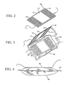
- FIG. 2 a capacitive sensor for use in conjunction with a blood product unit will now be described, the apparatus of FIG. 2 having a capacitive sensor 100.
- the capacitive sensor 100 preferably has two capacitor plates 110.
- the two capacitor plates 110 are preferably arranged on the same side of a preferably flat substrate 115.
- the capacitive sensor 100 also preferably has a baseplate 120.
- the two capacitor plates 110 and the base plate 120 are arranged such that the base plate 120 surrounds the two capacitor plates 110 and separates one of the two capacitor plates 110 from the other capacitor plate 110.
- the base plate 120 serves to eliminate the influence of the surface of a bag or other container when measuring a blood product unit contained in the bag. It is believed that using the apparatus of Fig. 2, optimum sensing sensitivity is achieved when each of the capacitor plates 110 is in a substantially rectangular configuration, each of the capacitor plates 110 being of substantially equal width and the distance between the facing ones Edges of the two capacitor plates 110 is approximately equal to the sum of the widths of the two capacitor plates 110, as can be seen in Fig. 2.
- the device of Figure 2 can be made using any of a number of methods well known in the art. For example, an unetched computer circuit board may be used and the circuit board then etched in a well-known manner to produce the device of FIG.
- the device of FIG. 3 preferably comprises the capacitive sensor 100 of FIG. 2 and also preferably a blood product unit 130.
- the blood product unit 130 typically includes a sack 140 which is typically made of a plastic.
- the capacitive sensor 100 is shown as being disposed on the bag 140.
- both of the capacitor plates 110 are mounted on one side of the bag 140 and are generally in contact therewith. It is also assumed that the configuration shown in Fig. 3 is preferably used. On the other hand, other configurations are possible, such as an arrangement such that the capacitor plates 110 are disposed on opposite sides of the bag 140 or even within the bag 140.
- FIG. 4 is a side view showing that the capacitive sensor 100 may also be permanently attached to the bag 140. In this case, the capacitive sensor 100 would typically be disposable.
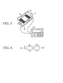
- the system of FIG. 5 includes the capacitive sensor 100 and the blood product unit 130 including the bag 140.
- the system of FIG. 5 also includes an impedance processor 150 operatively connected to the capacitive sensor 100.
- the impedance measuring unit 150 may be any suitable impedance measuring unit, such as an HP 4284A, commercially available from Hewlett-Packard.
- connection between the impedance processor 150 and the capacitive sensor 100 is formed using a plurality of wires.
- a wire is connected to each of the capacitor plates 110 while a wire is connected to the base plate 120; however, there may be other mounting arrangements suitable for the particular impedance processor 150.
- FIG. 6 additionally shows a schematic illustration of an electrical equivalent circuit diagram of a blood product unit together with the electrode arrangement of FIG. 2. The circuit of Figure 6 has been found suitable for use in the analysis of blood product units.
- the circuit of FIG. 6 includes three capacitors C 1 , C 2 and C 3 , a resistor R 1 and a Warburg impedance Z W.
- the impedance processor 150 has a function of calculating the Warburg impedance of the circuit of FIG. 6. It has been found that the calculated Warburg impedance for the circuit of Fig. 6 correlates well with bacterial growth in the blood product unit 130, with the Warburg impedance significantly decreasing at higher levels of bacterial contamination.
- FIG. 7 is a simplified illustration of a basic principle of a device for measuring a bacterial load in a liquid sample on a hose or tubular member according to the present invention.
- a container 160 such as a pouch containing a liquid, such as a blood product unit, has two stubs 161 and 162, for example be used to fill the container. Basically, the container 160 may take any other shape and may also have more than two ports, only one port, or no port at all.
- a tubular member 170 hereinafter referred to as tube 170
- a capacitive sensor 200 is attached to the tube 170.
- the capacitive sensor 200 consists essentially of two electrodes 202, which are arranged at a predetermined distance from each other in the longitudinal direction of the tube 170 so that they respectively surround the liquid contained in the tube 170.
Landscapes
- Chemical & Material Sciences (AREA)
- Health & Medical Sciences (AREA)
- Life Sciences & Earth Sciences (AREA)
- Physics & Mathematics (AREA)
- Pathology (AREA)
- Engineering & Computer Science (AREA)
- Biochemistry (AREA)
- General Health & Medical Sciences (AREA)
- General Physics & Mathematics (AREA)
- Immunology (AREA)
- Analytical Chemistry (AREA)
- Biomedical Technology (AREA)
- Dispersion Chemistry (AREA)
- Chemical Kinetics & Catalysis (AREA)
- Electrochemistry (AREA)
- Biophysics (AREA)
- Hematology (AREA)
- Molecular Biology (AREA)
- Urology & Nephrology (AREA)
- Food Science & Technology (AREA)
- Medicinal Chemistry (AREA)
- Investigating Or Analyzing Materials By The Use Of Electric Means (AREA)
- Measuring Or Testing Involving Enzymes Or Micro-Organisms (AREA)
Description
- Die vorliegende Erfindung bezieht sich im Allgemeinen auf ein Verfahren und eine Vorrichtung zum Überwachen von Mikroorganismenpopulationen, und bezieht sich insbesondere auf ein Verfahren und eine Vorrichtung zum schnellen, nicht-invasiven Testen flüssiger Proben wie etwa Blut und Blutprodukten. Als Blutprodukte kommen z.B. Erythrozyten, Thrombozyten (Blutplättchen), Granulozyten bzw. jeweils deren Konzentrate sowie Plasma und Plasmaderivate oder auch Vollblut in Betracht.
- Vorrichtungen zum Bestimmen der Mikroorganismenpopulation in einer Probe wie etwa einer Milchprobe oder einer Blutprobe bzw. Blutproduktprobe sind in der Technik wohl bekannt. Unter Verwendung von Näherungen der Wachstumsrate bekannter Bakterienpopulationen werden jeweilige gegenwärtige Populationen in die Vergangenheit extrapoliert. Beispielsweise werden während eines Wachstums von Bakterien in einer Probe Impedanzmessungen an der Probe durchgeführt. Da die Bakterienpopulation in der Probe wächst und einem Stoffwechsel unterliegt, ändert sich die Ionenkonzentration der Probe, und es ändern sich die elektrischen Eigenschaften der Probe, insbesondere seine Impedanz. Durch Messen der Impedanzänderungen bei konstanter Temperatur kann die Anzahl von Mikroorganismen abgeschätzt werden.
- Zusätzlich zu unvermeidlichen Fehlern, welche sich aus den oben erwähnten Extrapolation ergeben, sind jedoch existierende Verfahren und Vorrichtungen zum Überwachen von Bakterienpopulationen im Allgemeinen extrem ungenau und erfordern eine lange Brut- und Überwachungsdauer, bevor endgültige Ergebnisse erzielt werden. Dies liegt daran, daß signifikante Änderungen in den elektrischen Eigenschaften der beimpften Probe, welche nicht einer nicht-bakteriellen Aktivität in der Probe zugeordnet werden können, nur bei hohen Konzentrationen von Mikroorganismen auftreten. Nachdem längere Brutdauern erforderlich sind, um hohe Konzentrationen von Mikroorganismen zu erhalten, werden die Extrapolationen über eine längere Zeitdauer vorgenommen, und daher sind die extrapolierten Ergebnisse von erheblich geringerer Genauigkeit.
- Ein allgemeiner Ansatz zum Bestimmen der Bakterienpopulation flüssiger Proben, insbesondere von Milchproben und Blutprodukt-Einheiten, basiert auf einer Messung der Impedanz über die Probe. Nachdem die Impedanz einer Probe im Allgemeinen mit wachsender Bakterienpopulation abfällt, bilden Impedanzmessungen über die Probe eine Grundlage zum Abschätzen der Bakterienpopulation in der Probe.
- Für Impedanzmessungen in flüssigen Proben wird Elektroden in der Probe im Allgemeinen eher eine Wechselspannung als eine Gleichspannung zugeführt, nachdem eine Gleichspannung dazu neigt, eine schnelle, isolierende Polarisierung an der Schnittstelle zwischen der Flüssigkeit und den Elektroden zu verursachen. Wenn eine hochfrequente Wechselspannung von typischerweise 1 kHz oder mehr verwendet wird, wird die Wirkung einer solchen Polarisierung auf die gemessenen Impedanzen in hohem Maße reduziert. Bestehende Vorrichtungen zum Zählen von Mikroorganismen verwenden typischerweise eine Wechselspannung von 1 kHz oder 10 kHz.
- Ein Nachteil vieler Bakterienwachstumstester besteht darin, daß sie invasiv und ungenau sind und lange Brutzeiten erfordern, um vernünftige Ergebnisse zu erzielen. Dies liegt hauptsächlich an der Tatsache, daß signifikante Impedanzänderungen, typischerweise einige Prozent, nur nach langen Brutzeiten erscheinen, wenn sehr hohe Bakterienkonzentrationen, typischerweise ab 106 Bakterien pro cm3 erreicht sind. Zusätzlich zu ihrer geringen Empfindlichkeit auf Änderungen in kleinen Bakterienpopulationen sind existierende Testgeräte extrem empfindlich hinsichtlich Temperaturänderungen in der Probe, welche sowohl die Wachstumsrate der Bakterienpopulation als auch, was noch wichtiger ist, den Betrag der gemessenen Impedanzen beeinflußt. Hinzu kommt, daß, nachdem eine Evaluierung von Populationen in der Vergangenheit im Allgemeinen auf einer Messung der Probe zu Beginn einer Bebrütung als einem Bezugspunkt basiert und zum Zeitpunkt des Testens kein Bezugspunkt zur Verfügung steht, eine hohe Erfassungsschwelle erforderlich ist, selbst wenn die Temperatur streng stabilisiert ist.
- Ein Verfahren zum Erfassen von Bakterien in einer Weinprobe durch Messen der Impedanz der Probe ist in P.A. Henschke & D. Susan Thomas "Detection of Wine-Spoiling Jeasts by Electronic Methods", Journal of Applied Bacteriology 1988, Band 64, Seiten 123-133 beschrieben. Dieser Artikel schlägt die Verwendung einer ein sterilisiertes Medium als Referenz zu der getesteten Weinprobe enthaltenden Kammer vor. Der Bezug auf das sterilisierte Medium gleicht Änderungen in der Impedanz der Weinprobe auf Grund von physikalischen und chemischen Faktoren, die nicht auf ein mikrobielles Wachstum bezogen sind, aus. Um zwischen Weinhefen und Fremdhefen zu unterscheiden, beschäftigt sich dieser Artikel mit der Möglichkeit, das mikrobielle Wachstum in den Weinhefen unter Verwendung von Ethanol zu verzögern.
- Vorrichtungen zum Überwachen von Bakterien, welche zur Aufnahme einer Mehrzahl von Flüssigkeitsproben angepaßt sind, wobei jede Probe mit einem Paar von Elektroden versehen ist, um Strom hindurchzuschicken, sind bekannt. Solche Vorrichtungen, welche typischerweise als Mehrsensor-Impedanzmessvorrichtungen bezeichnet werden, sind zur gleichzeitigen invasiven Überwachung einer Mehrzahl von flüssigen Proben hilfreich. Beispiele solcher Mehrprobentester sind in den US-Patentschriften Nrn. 3,890,201 und 4,072,578 beschrieben.
- Die Vorrichtungen der US-Patente Nrn. 3,890,201 und 4,072578 weisen eine Mehrzahl von individuellen Kammern zur Aufnahme einer jeweiligen Mehrzahl separater beimpfter Proben auf. Die in dem
US-Patent Nr. 4,072,578 beschriebene Vorrichtung weist auch eine computerisierte Einrichtung zum Steuern der Analyse des bakteriellen Wachstums in den separaten Kammern auf. - Eine Mehrkammertestvorrichtung auf der Grundlage der oben beschriebenen Prinzipien ist von Malthus Instruments Ltd., England, unter dem Handelsnamen Malthus 2000 Microbiology System erhältlich. Diese Vorrichtung mißt die Leitfähigkeit von bis zu 240 separaten Proben durch Anlegen einer Wechselspannung von 10 kHz über Elektroden, welche den Proben zugeordnet sind. Das mikrobielle Wachstum in jeder Probe wird durch Messen von Änderungen in der Leitfähigkeit einer Base, welche metabolisches CO2 absorbiert, unter Verwendung eines computerisierten mikrobiologischen Analysegeräts erfaßt.
- Es sollte jedoch verstanden werden, daß die vorgenannten Nachteile bestehender Einzelkammervorrichtungen, z.B. Invasivität und eine niedrige Empfindlichkeit, welche in einer geringen Genauigkeit resultieren und lange Testzeiten erfordern, ebenso für jede Kammer bestehender Mehrkammervorrichtungen gelten. Es sollte ebenfalls verstanden werden, daß keine der bestehenden Mehrkammervorrichtungen eine genaue Erfassung einer kleinen Anzahl von Mikroorganismen in Flüssigkeitsproben erlaubt.
- Es ist zu verstehen, daß Techniken zur Analyse elektrischer Eigenschaften, insbesondere die Impedanzspektroskopie, in den letzten zehn Jahren beträchtlich verbessert worden sind. Daher können nun durch Entwerfen geeigneter empirischer Modelle des elektrischen Verhaltens einer Probe, d.h. Entwerfen von Ersatzschaltbildern der Probe, und durch Anwenden von in höherem Maße automatisierten, nicht kontaktierenden und genaueren Impedanzmeßtechniken eine endgültigere Evaluierung der elektrischen Eigenschaften von Proben möglich sein kann. Eine allgemeine Darstellung des Gebiets der Impedanzspektroskopie kann in J. Ross MacDonald "Impedance Spectroscopie, Emphasising Solid Materials and Systems", New York, 1987, gefunden werden. Bioanalytische Anwendungen der Impedanzspektroskopie können in Douglas B. Kell "The Principles and Potential of Electrical Admittance Spectroscopy: an Introduction", aus "Biosensors, Fundamentals and Applications", herausgegeben von Anthony P. F. Turner et al., Oxford University Press, 1987, gefunden werden.
- Ein System zum Erfassen des Vorliegens von Mikroorganismen in einer Probe wird in den
US-Patentschriften Nrn. 4,009,078 ,4,200,493 und4,246,343 , jeweils unter dem Namen von Wilkens et al., beschrieben. Das beschriebene System beinhaltet eine Kultivierung von Mikroorganismen in einem Wachstumsmedium, welches sich in Kontakt mit einer Meßelektrode befindet, und eine Meßelektrode, während Änderungen im Potential zwischen den Elektroden gemessen werden. - Als nächstliegender Stand der Technik sind die Patentschrift
EP0803728 und die Veröffentlichung "Microscale electronic detection of bacterial metabolism" von R. Gömez et al (Sensors and Actuators B 86 (2002), 198-208) zu nennnen.EP0803728 beschreibt eine nicht-invasive Impedanzmessung zur Überwachung mikrobiellen Wachstums. Der Artikel von Gómez beschreibt eine invasive Messung, die die Berechnung einer Warburg-Impedanz beinhaltet. - Die Aufgabe der vorliegenden Erfindung besteht darin, eine wesentlich verbesserte Vorrichtung und ein entsprechendes Verfahren zum Überwachen der Mikroorganismenpopulation in einer Probe unter Verwendung einer Impedanzanalyse zu schaffen.
- Diese Aufgabe wird durch die Merkmale der unabhängigen Ansprüche gelöst. Vorteilhafte Ausführungsformen und Weiterbildungen der vorliegenden Erfindung bilden den Gegenstand der abhängigen Ansprüche.
- Das Verfahren und die Vorrichtung der vorliegenden Erfindung erfordert kürzere Überwachungs- und Brutzeiten als vorbekannte Verfahren und Vorrichtungen. Außerdem ermöglicht die vorliegende Vorrichtung und das vorliegende Verfahren eine genauere Messung extrem kleiner Mikroorganismenpopulationen. Weiterhin sind das Verfahren und die Vorrichtung insbesondere zum nicht-invasiven Testen von flüssigen Proben in rohr- oder schlauchartigen Leitungen wie etwa in Zu- und Ableitungen von Behältern geeignet. Eine weitere Ausführungsform ist insbesondere zum nicht-invasiven Testen von Blutprodukt-Einheiten wie zum Beispiel Blutplättchen-Einheiten vorzugsweise in der Form von Beuteln geeignet.
- Der vorliegenden Erfindung liegt die Grundidee zugrunde die gemessenen Impedanzen durch eine geeignete Schaltungsanordnung in vordefinierte reale und/oder imaginäre, d.h. komplexe, Komponenten zu zerlegen. Es hat sich herausgestellt, daß einige dieser Komponenten hinsichtlich Änderungen in der Bakerienpopulation in der Probe empfindlicher sind als die Gesamtimpedanz der Probe. Es erweist sich daher als vorteilhaft, die Bakterienpopulation in der Probe auf der Grundlage der stärker reagierenden Komponente zu analysieren.
- Für die Anwendung an Milchproben und Plasmabehältern hat es sich als vorteilhaft erwiesen, die Bakterienpopulation auf der Grundlage einer Messung der Warburg-Impedanz zu analysieren. Dabei wird ein Element eines Ersatzschaltbildes, entweder von Milchproben oder von Blutprodukt-Einheiten, identifiziert und analysiert, wobei das Element jeweils besonders empfindlich hinsichtlich Änderungen der Bakterienkonzentration der Milch oder des Blutprodukt ist.
- Weiter hat es sich als vorteilhaft erwiesen, in dem oben genannten Verfahren zum Evaluieren der Mikroorganismenpopulation in einer Flüssigkeitsprobe ein Ersatzschaltbild der Flüssigkeitsprobe zu definieren, den Betrag wenigstens eines Elements des Ersatzschaltbildes zu bestimmen, und die Anzahl von Mikroorganismen in der Probe auf der Grundlage des wenigstens einen bestimmten Elements zu evaluieren.
- Es ist auch vorteilhaft, eine Wechselspannung mit einer Mehrzahl von Frequenzen über wenigstens einem Abschnitt der Probe anzulegen, die Impedanz über wenigstens den Abschnitt der Flüssigkeitsprobe in Reaktion auf wenigstens einige der Mehrzahl von Wechselfrequenzen zu messen, wenigstens ein Element eines elektrischen Ersatzschaltbildes der Probe auf der Grundlage der über wenigstens den Abschnitt gemessenen Impedanzen zu berechnen und die Mikroorganismenpopulation in der Probe auf der Grundlage des wenigstens einen berechneten Elements zu evaluieren.
- Das Element beinhaltet eine warburg-Impedanz. Zusätzlich kann die Flüssigkeitsprobe für eine vorgewählte Zeitdauer vor der Messung der Impedanz bebrütet werden.
- Eine entsprechende Vorrichtung zum Evaluieren der Mikroorganismenpopulation in einer Flüssigkeitsprobe weist einen zum Aufnehmen der Flüssigkeitsprobe geeigneten Behälter und einen Impedanzprozessor, welcher eine Wechselspannung bei einer Mehrzahl von Frequenzen über wenigstens einen Abschnitt der Flüssigkeitsprobe anlegt und die Impedanz über wenigstens den Abschnitt der Flüssigkeitsprobe in Reaktion auf wenigstens einige der Wechselfrequenzen mißt, auf, wobei der Impedanzprozessor eine Schaltungsanordnung zum Berechnen einer Warburg-Impedant der Probe auf der Grundlage der über wenigstens den Abschnitt gemessenen Impedanz und zum Evaluieren der Mikroorganismenpopulation in der Probe auf der Grundlage des wenigstens einen berechneten Elements aufweist.
- Der Impedanzprozessor ist elektrisch in nicht-invasiver Weise mit der Flüssigkeitsprobe verbunden. In einer speziellen Bauform weist der Impedanzprozessor zwei Kondensatorplatten zum elektrischen nicht-invasiven Verbinden des Impedanzprozessors mit der Flüssigkeitsprobe auf. Die Flüssigkeitsprobe wiederum weist eine Mehrzahl von Seiten auf, und beide der zwei Kondensatorplatten sind operativ mit einer der Mehrzahl von Seiten verbunden.
- Vorteilhafterweise weist die oben genannte Vorrichtung eine Grundplatte auf, und die Grundplatte und die zwei Kondensatorplatten sind im wesentlichen koplanar zueinander, wobei die Grundplatte die zwei Kondensatorplatten umgibt und trennt.
- Ein entsprechender kapazitiver Sensor zur Verwendung beim Messen der Impedanz einer Flüssigkeitsprobe weist zwei Kondensatorplatten und eine Grundplatte auf, wobei die Grundplatte und die zwei Kondensatorplatten im wesentlichen koplanar zueinander sind und wobei die Grundplatte die zwei Kondensatorplatten umgibt und trennt. Der kapazitive Sensor kann dauerhaft an der Blutproben-Einheit angebracht sein.
- Ein entsprechender Flüssigkeitsprobenhalter zur Verwendung bei einer Messung der Impedanz einer Flüssigkeitsprobe weist einen Behälter zum Aufnehmen der Flüssigkeitsprobe sowie einen kapazitiven Sensor mit zwei Kondensatorplatten und einer Grundplatte auf, wobei die Grundplatte und die zwei Kondensatorplatten im wesentlichen koplanar sind und wobei die Grundplatte die zwei Kondensatorplatten umgibt und trennt.
- Die oben genannten Bauformen sind besonders geeignet zur Anwendung an einer Blutprodukt-Einheit in Beutelform. Die flüssige Probe kann eine Blutplättchen-Einheit aufweisen. Die Frequenzen können zwischen 10 Hz und 10 MHz liegen.
- Gemäß der vorliegenden Erfindung wird das oben genannte Verfahren beispielsweise auf die Bestimmung der Mikroorganismenpopulation in einer in einem schlauch- oder röhrenförmigen Bauelement befindlichen flüssigen Probe angewendet.
- Eine an diesen Anwendungsfall angepaßte Vorrichtung zum Bestimmen der Mikroorganismenpopulation in einer flüssigen Probe weist gemäß der Erfindung ein schlauchförmiges oder röhrenförmiges Bauelement zum Aufnehmen oder Leiten der flüssigen Probe darin; und einen Impedanzprozessor, welcher eine Wechselfrequenz bei einer Mehrzahl von Frequenzen über wenigstens einen Abschnitt der flüssigen Probe anlegt und die Impedanz über wenigstens den Abschnitt der flüssigen Probe in Reaktion auf wenigstens einige der Wechselfrequenzen mißt, auf, wobei der Impedanzprozessor eine Mehrzahl von Schaltungsanordnungen zum Berechnen wenigstens eines Elements eines elektrischen Ersatzschaltbildes der Probe auf der Grundlage der über wenigstens den Abschnitt gemessenen Impedanzen und zum Bestimmen der Mikroorganismenpopulation in der Probe auf der Grundlage des wenigstens einen berechneten Elements aufweist.
- Bei der erfindungsgemäßen Vorrichtung weist der Impedanzprozessor vorzugsweise zwei Kondensatorelektroden zum elektrischen nicht-invasiven Verbinden des Impedanzprozessors mit der flüssigen Probe auf, die um die flüssige Probe herum mit einem vorbestimmten Abstand in axialer Richtung des schlauchförmigen oder röhrenförmigen Bauelements voneinander angeordnet sind.
- Ein kapazitiver Sensor zur Verwendung beim Messen der Impendanz einer in einem schlauchförmigen oder röhrenförmigen Bauelement befindlichen flüssigen Probe weist gemäß der Erfindung zwei Elektroden auf, die unter einem vorbestimmten Abstand in axialer Richtung des schlauchförmigen oder röhrenförmigen Bauelements voneinander um die flüssige Probe herum angeordnet sind.
- Die vorliegende Erfindung wird aus der nachfolgenden genauen Beschreibung der bevorzugten Ausführungsformen der vorliegenden Erfindung ersichtlich, welche in Verbindung mit den beiliegenden Zeichnungen beschrieben werden, in welchen:
- Fig. 1 eine schematische Darstellung eines elektrischen Ersatzschaltbildes von Milch ist;
- Fig. 2 eine vereinfachte Darstellung eines erfindungsgemäßen kapazitiven Sensors zur Verwendung an einer Blutprodukt-Einheit ist;
- Fig. 3 eine vereinfachte Darstellung der Vorrichtung von Fig. 2 bei Verwendung mit einer Blutprodukt-Einheit ist;
- Fig. 4 eine Seitenansicht der Vorrichtung von Fig. 3 ist;
- Fig. 5 eine vereinfachte Darstellung eines Systems zur Messung einer Blutprodukt-Einheit unter Einschluß der Vorrichtung von Fign. 3 und 4 ist;
- Fig. 6 eine schematische Darstellung eines elektrischen Ersatzschaltbildes einer Blutprodukt-Einheit zusammen mit der Elektrodenanordnung von Fig. 2 ist;
- Fig. 7 eine vereinfachte Darstellung einer Vorrichtung zur Messung einer bakteriellen Belastung in einer flüssigen Probe gemäß der vorliegenden Erfindung ist;
- Es hat sich herausgestellt, daß empfindlichere Messungen erhalten werden können, wenn nicht die Gesamtimpedanz der Proben, sondern nur eine bestimmte Komponente der Probenimpedanzen durch den Impedanzprozessor gemessen wird. Um eine gewünschte Impedanzkomponente zu synthetisieren, ist es erforderlich, ein elektrisches Ersatzschaltbild der im Test befindlichen Probe zu konstruieren, in welchem die gewünschte Impedanz als ein unterscheidbares Schaltungselement enthalten ist.
- Nachdem die Impedanz des Ersatzschaltbildes definitionsgemäß der Impedanz der im Test befindlichen Probe äquivalent ist, ist es möglich, einen Satz von nichtlinearen Gleichungen in Abhängigkeit von dem Probenmaterial durch Messen der Probenimpedanz bei einer Mehrzahl von Wechselfrequenzen aufzustellen. Die Anzahl der erforderlichen Impedanzmessungen entspricht der Anzahl der Unbekannten in dem Ersatzschaltbild. Vorzugsweise werden eine Mehrzahl von Wechselfrequenzen in dem Bereich von etwa 10 Hz bis 10 MHz verwendet, während bei vorbekannten Vorrichtungen, die eine konstante Frequenz verwenden, typischerweise 1 kHz oder 10 kHz verwendet werden.
- Für eine Übersicht über Ersatzschaltbilder in der Impedanzspektroskopie sei auf J. Ross MacDonald, "Impedance Spectroscopie, Emphasising Solid Materials and Systems", New York, 1987 verwiesen. Bezüglich Ersatzschaltbildern für Mikroorganismenwachstum sei auf J. C. S. Richard, A. C. Jason, G. Hobbs, D. M. Gibson und R. H. Christie, "Electronic Measurement of Bacterial Growth", in "Journal of Physics and Electronics Scientific Instruments", Band II, 1978, verwiesen.
- Fig. 1 stellt ein bevorzugtes Ersatzschaltbild zur invasiven Messung von Milchproben dar. Wie in Fig. 1 gesehen werden kann, beinhaltet das Ersatzschaltbild drei Widerstände R1, R2 und R3, zwei Kondensatoren C1 und C2 und eine als ZW bezeichnete Komponente, die als Warburg-Impedanz bekannt ist. Die Warburg-Impedanz, wie sie im Stand der Technik bekannt ist, ist durch die nachfolgende Gleichung gegeben:

- ZW
- die Warburg-Impedanz ist;
- W
- die Warburg-Variable ist;
- j
- die imaginäre Impedanznotation ist; und
- f
- die verwendete Wechselfrequenz ist.
- Es hat sich herausgestellt, daß die Warburg-Impendanz wenigstens zehnmal so empfindlich auf Änderungen in der Anzahl von Bakterien in Milch reagiert als die Gesamtimpedanz der Schaltung.
- Mit Bezug auf Fig. 2 wird nun ein kapazitiver Sensor zur Verwendung im Zusammenhang mit einer Blutprodukt-Einheit beschrieben werden, wobei die Vorrichtung von Fig. 2 einen kapazitven Sensor 100 aufweist.
- Der kapazitve Sensor 100 weist vorzugsweise zwei Kondensatorplatten 110 auf. Die zwei Kondensatorplatten 110 sind vorzugsweise auf der gleichen Seite eines vorzugsweise flachen Substrats 115 angeordnet. Der kapazitive Sensor 100 weist ebenfalls vorzugsweise eine Grundplatte 120 auf. Vorzugsweise sind die zwei Kondensatorplatten 110 und die Grundplatte 120 derart angeordnet, daß die Grundplatte 120 die zwei Kondensatorplatten 110 umgibt und die eine der zwei Kondensatorplatten 110 von der anderen Kondensatorplatte 110 trennt.
- Die Grundplatte 120 dient dazu, den Einfluß der Oberfläche eines Beutels oder anderen Behälters auszuschließen, wenn eine in dem Beutel enthaltene Blutprodukt-Einheit gemessen wird. Es wird angenommen, daß bei Verwendung der Vorrichtung von Fig. 2 eine optimale Meßempfindlichkeit erreicht wird, wenn sich jede der Kondensatorplatten 110 in einer im wesentlichen rechteckigen Konfiguration befindet, jede der Kondensatorplatten 110 von im wesentlichen gleicher Breite ist und der Abstand zwischen den einander zugewandten Kanten der zwei Kondensatorplatten 110 näherungsweise gleich der Summe der Breiten der zwei Kondensatorplatten 110 ist, wie in Fig. 2 gesehen werden kann.
- Die Vorrichtung von Fig. 2 kann unter Verwendung eines beliebigen einer Anzahl von Verfahren hergestellt werden, die im Stand der Technik wohlbekannt sind. Beispielsweise kann eine ungeätzte Computerleiterplatte verwendet und die Leiterplatte dann in wohlbekannter Weise geätzt werden, um die Vorrichtung von Fig. 2 herzustellen.
- Anhand von Fig. 3 wird nun eine Verwendung der Vorrichtung von Fig. 2 an einer Blutprodukt-Einheit beschrieben werden.
- Die Vorrichtung von Fig. 3 weist vorzugsweise den kapazitiven Sensor 100 von Fig. 2 und ebenfalls vorzugsweise eine Blutprodukt-Einheit 130 auf. Die Blutprodukt-Einheit 130 weist üblicherweise einen Sack 140 auf, welcher typischerweise aus einem Kunststoff hergestellt ist. In Fig. 3 ist der kapazitive Sensor 100 so dargestellt, daß er auf dem Sack 140 angeordnet ist.
- Es wird angenommen, daß beide der Kondensatorplatten 110 auf einer Seite des Sacks 140 montiert sind und sich im allgemeinen im Kontakt damit befinden. Es wird ebenfalls angenommen, daß die in Fig. 3 gezeigte Konfiguration vorzugsweise angewendet wird. Andererseits sind auch andere Konfigurationen möglich, wie etwa eine Anordnung derart, daß die Kondensatorplatten 110 auf entgegengesetzten Seiten des Sacks 140 oder auch innerhalb des Sacks 140 angeordnet sind.
- Zusätzlich wird nun auf Fig. 4 Bezug genommen, welche eine Seitenansicht ist, die zeigt, daß der kapazitive Sensor 100 auch dauerhaft an dem Sack 140 angebracht sein kann. In diesem Fall wäre der kapazitive Sensor 100 typischerweise wegwerfbar.
- Mit Bezug auf Fig. 5 wird nun ein System zum Messen einer Blutprodukt-Einheit beschrieben werden, welches die Vorrichtungen von Fign. 3 und 4 beinhaltet. Das System von Fig. 5 weist den kapazitiven Sensor 100 und die Blutprodukt-Einheit 130 einschließlich des Sacks 140 auf. Das System von Fig. 5 weist ebenfalls einen Impedanzprozessor 150 auf, der operativ mit dem kapazitiven Sensor 100 verbunden ist. Die Impedanzmeßeinheit 150 kann jede geeignete Impedanzmeßeinheit sein, wie etwa ein HP 4284A, der von Hewlett-Packard käuflich zu erwerben ist.
- Typischerweise ist die Verbindung zwischen dem Impedanzprozessor 150 und dem kapazitiven Sensor 100 unter Verwendung einer Mehrzahl von Drähten ausgebildet. Typischerweise ist ein Draht mit jeder der Kondensatorplatten 110 verbunden, während ein Draht mit der Grundplatte 120 verbunden ist; es kann jedoch auch andere Anordnungen der Befestigung geben, die für den besonderen Impedanzprozessor 150 geeignet sind.
- Nun wird die Betriebsweise des Systems von Fig. 5 kurz beschrieben werden. Der kapazitive Sensor 100 ist in Kontakt mit der Blutprodukt-Einheit 130 angeordnet. Der Impedanzprozessor 150 weist eine Funktion auf, die Impedanz des Systems, welches den kapazitiven Sensor 100 und die Blutprodukt-Einheit 130 aufweist, bei einer Mehrzahl von Wechselfrequenzen zu messen, wie zuvor beschrieben, und ist dann tätig, um eine Ersatzschaltbildanalyse auszuführen, wie zuvor beschrieben. In Fig. 6 ist zusätzlich eine schematische Darstellung eines elektrischen Ersatzschaltbildes einer Blutprodukt-Einheit zusammen mit der Elektrodenanordnung von Fig. 2 gezeigt. Die Schaltung von Fig. 6 hat sich zur Verwendung bei der Analyse von Blutprodukt-Einheiten als geeignet erwiesen.
- Die Schaltung von Fig. 6 beinhaltet drei Kondensatoren C1, C2 und C3, einen Widerstand R1 und eine Warburg-Impedanz ZW.
- Der Impedanzprozessor 150 weist eine Funktion auf, die Warburg-Impedanz der Schaltung von Fig. 6 zu berechnen. Es hat sich herausgestellt, daß die berechnete Warburg-Impedanz für die Schaltung von Fig. 6 gut mit einem bakteriellen Wachstum in der Blutprodukt-Einheit 130 korreliert, wobei die Warburg-Impedanz bei höheren Graden bakterieller Kontamination signifikant abfällt.
- Fig. 7 ist eine vereinfachte Darstellung eines Grundprinzips einer Vorrichtung zum Messen einer bakteriellen Belastung in einer flüssigen Probe an einem schlauch- oder röhrenförmigen Bauteil gemäß der vorliegenden Erfindung. Ein Behälter 160 wie etwa ein Beutel, der eine Flüssigkeit enthält, wie etwa eine Blutprodukt-Einheit, weist zwei Stutzen 161 und 162 auf, die beispielsweise zum Befüllen des Behälters verwendet werden. Grundsätzlich kann der Behälter 160 jede andere Form annehmen und kann auch mehr als zwei Stutzen, nur einen Stutzen oder überhaupt keinen Stutzen aufweisen. An dem Behälter ist ein schlauch- bzw. röhrenförmiges Bauteil 170 (nachstehend als Schlauch 170 bezeichnet) verbunden, durch welchen bzw. in welchem eine Flüssigkeit in den Behälter oder aus dem Behälter strömen kann oder auch bewegungslos stehen kann. An dem Schlauch 170 ist ein kapazitiver Sensor 200 angebracht. Der kapazitive Sensor 200 besteht im wesentlichen aus zwei Elektroden 202, die mit einem vorbestimmten Abstand voneinander in Längsrichtung des Schlauchs 170 so angeordnet sind, daß sie jeweils die in dem Schlauch 170 befindliche Flüssigkeit umgeben.
Claims (11)
- Verfahren zum Bestimmen der Mikroorganismenpopulation in einer flüssigen Probe, welches aufweist:Anlegen von einer Mehrzahl von Wechselspannungen einer Mehrzahl von Frequenzen über wenigstens einen Abschnitt der flüssigen Probe;Messen der Impedanz über den wenigstens einen Abschnitt der flüssigen Probe als Reaktion auf wenigstens einige der Mehrzahl von Frequenzen;Berechnen wenigstens einer Impedanz eines Elements eines elektrischen Ersatzschaltkreises der flüssigen Probe auf der Grundlage der über den wenigstens einen Abschnitt gemessenen Impedanz, wobei das wenigstens eine berechnete Element eine Warburg-Impedanz aufweist; undBestimmen der Mikroorganismenpopulation in der flüssigen Probe auf der Grundlage der Impedanz des wenigstens einen berechneten Elementsdadurch gekennzeichnet, daß
das Messen der Impedanz nicht-invasiv durchgeführt wird. - Verfahren gemäß Anspruch 1, dadurch gekennzeichnet, daß die Frequenzen zwischen 10 Hz und 10 MHz liegen.
- Verfahren gemäß Anspruch 1, dadurch gekennzeichnet, daß es weiter eine Bebrütung der flüssigen Probe für eine vorbestimmte Zeitdauer vor der Messung der Impedanz beinhaltet.
- Verfahren gemäß einem der Ansprüche 1 bis 3, dadurch gekennzeichnet, daß sich die flüssige Probe in einem schlauchförmigen oder röhrenförmigen Bauelement (170) befindet.
- Vorrichtung zum Bestimmen der Mikroorganismenpopulation in einer flüssigen Probe, welche aufweist:einen Behälter zum Aufnehmen oder Leiten der flüssigen Probe darin; undeinen Impedanzprozessor, welcher eingerichtet ist um eine Mehrzahl von Wechselspannungen einer Mehrzahl von Frequenzen über wenigstens einen Abschnitt der flüssigen Probe anzulegen und die lmpedanz über den wenigstens einen Abschnitt der flüssigen Probe als Reaktion auf wenigstens einige der Mehrzahl von Frequenzen zu messen, wobeider Impedanzprozessor eine Mehrzahl von Schaltungsanordnungen zum Berechnen einer Impedanz wenigstens eines Elements eines elektrischen Ersatzschaltkreises der flüssigen Probe auf der Grundlage der über wenigstens den Abschnitt gemessenen Impedanz und zum Bestimmen der Mikroorganismenpopulation in der flüssigen Probe auf der Grundlage der Impedanz des wenigstens einen berechneten Elements aufweist, und das wenigsten eine berechnete Element eine Warburg-Impedanz aufweist,
dadurch gekennzeichnet, daß der Behälter so eingerichtet ist, daß
der Impedanzprozessor mit der flüssigen Probe nicht-invasiv verbunden ist. - Vorrichtung gemäß Anspruch 5, dadurch gekennzeichnet, daß die Wechselfrequenzen zwischen 10 Hz und 10 MHz liegen.
- Vorrichtung gemäß Anspruch 5, dadurch gekennzeichnet, daß der Impedanzprozessor zwei Kondensatorelektroden (202) zum elektrischen nicht-invasiven Verbinden des Impedanzprozessors mit der flüssigen Probe aufweist.
- Vorrichtung gemäß Anspruch 7, dadurch gekennzeichnet, daß die flüssige Probe eine Mehrzahl von Seiten aufweist und beide der zwei Kondensatorplatten operativ mit einer der Mehrzahl von Seiten verbunden sind.
- Vorrichtung gemäß Anspruch 7, dadurch gekennzeichnet, daß sie weiterhin eine Grundplatte aufweist, wobei die Grundplatte und die zwei Kondensatorplatten im wesentlichen koplanar zueinander sind und die Grundplatte die zwei Kondensatorplatten umgibt und trennt.
- Vorrichtung gemäß einem der Ansprüche 7 bis 9, dadurch gekennzeichnet, daß der Behälter ein schlauchförmiges oder röhrenförmiges Bauelement (170) ist.
- Vorrichtung gemäß Anspruch 7, dadurch gekennzeichnet, daß die Kondensatorelektroden (202) um die flüssige Probe herum mit einem vorbestimmten Abstand in axialer Richtung des schlauchförmigen oder röhrenförmigen Bauelements (170) voneinander angeordnet sind.
Applications Claiming Priority (3)
| Application Number | Priority Date | Filing Date | Title |
|---|---|---|---|
| EP03400017A EP1473359A1 (de) | 2003-05-02 | 2003-05-02 | Nicht-invasive schnelle Bestimmung des Bakteriengehalts in Blut und Blutprodukten |
| DE2003151390 DE10351390A1 (de) | 2003-11-04 | 2003-11-04 | Verfahren und Vorrichtung zur schnellen Bestimmung einer bakteriellen Belastung in Blut und Blutprodukten |
| PCT/EP2004/004682 WO2004096974A2 (de) | 2003-05-02 | 2004-05-03 | Verfahren und vorrichtung zur schnellen bestimmung einer bakteriellen belastung in blut und blutprodukten |
Publications (2)
| Publication Number | Publication Date |
|---|---|
| EP1633849A2 EP1633849A2 (de) | 2006-03-15 |
| EP1633849B1 true EP1633849B1 (de) | 2007-07-11 |
Family
ID=33420033
Family Applications (1)
| Application Number | Title | Priority Date | Filing Date |
|---|---|---|---|
| EP04730852A Expired - Lifetime EP1633849B1 (de) | 2003-05-02 | 2004-05-03 | Verfahren und vorrichtung zur schnellen bestimmung einer bakteriellen belastung in blut und blutprodukten |
Country Status (4)
| Country | Link |
|---|---|
| EP (1) | EP1633849B1 (de) |
| AT (1) | ATE366795T1 (de) |
| DE (1) | DE502004004304D1 (de) |
| WO (1) | WO2004096974A2 (de) |
Families Citing this family (3)
| Publication number | Priority date | Publication date | Assignee | Title |
|---|---|---|---|---|
| US9316605B2 (en) | 2010-09-22 | 2016-04-19 | Delaval Holding Ab | Determination of attributes of liquid substances |
| RU2477310C1 (ru) * | 2011-08-08 | 2013-03-10 | Федеральное бюджетное учреждение науки "Государственный научный центр вирусологии и биотехнологии "Вектор" (ФБУН ГНЦ ВБ "Вектор") | Биологический микрочип на основе диэлектрофореза, система для экспресс-идентификации вирусов и способ экспресс-идентификации вирусов с их использованием |
| WO2022207020A1 (en) * | 2021-04-01 | 2022-10-06 | Univerzita Karlova, Lékařská fakulta v Plzni | Non-contact sensor and measuring system for indicating presence of blood and infusion fluids and their identification |
Family Cites Families (6)
| Publication number | Priority date | Publication date | Assignee | Title |
|---|---|---|---|---|
| DE2032725A1 (de) * | 1970-07-02 | 1972-01-05 | Leybold Heraeus Gmbh & Co Kg | Dielektrische Meßzelle und Meßverfahren hierzu |
| IT1258181B (it) * | 1992-08-05 | 1996-02-20 | Apparecchiatura per la determinazione della frazione d'acqua in una corrente di idrocarburi luquidi anche in presenza di gas | |
| US5583432A (en) * | 1994-04-11 | 1996-12-10 | Sci-Nostics Limited | Electrical method and apparatus for non-contact determination of physical and/or chemical properties of a sample, particularly of blood |
| US5459406A (en) * | 1994-07-01 | 1995-10-17 | Cornell Research Foundation, Inc. | Guarded capacitance probes for measuring particle concentration and flow |
| EP0803728A1 (de) * | 1996-04-24 | 1997-10-29 | Celsis International Plc | Verfahren zum Messen der Leitfähigkeit von Flüssigkeiten |
| DE19651355B4 (de) * | 1996-12-10 | 2004-03-18 | Fresenius Medical Care Deutschland Gmbh | Gasblasendetektor |
-
2004
- 2004-05-03 EP EP04730852A patent/EP1633849B1/de not_active Expired - Lifetime
- 2004-05-03 DE DE502004004304T patent/DE502004004304D1/de not_active Expired - Fee Related
- 2004-05-03 AT AT04730852T patent/ATE366795T1/de not_active IP Right Cessation
- 2004-05-03 WO PCT/EP2004/004682 patent/WO2004096974A2/de not_active Ceased
Also Published As
| Publication number | Publication date |
|---|---|
| WO2004096974A8 (de) | 2005-02-17 |
| WO2004096974A3 (de) | 2005-06-09 |
| EP1633849A2 (de) | 2006-03-15 |
| DE502004004304D1 (de) | 2007-08-23 |
| ATE366795T1 (de) | 2007-08-15 |
| WO2004096974A2 (de) | 2004-11-11 |
Similar Documents
| Publication | Publication Date | Title |
|---|---|---|
| DE69321592T2 (de) | Verfahren und vorrichtung zur feststellung einer eigenschaft einer probe | |
| DE3884136T2 (de) | Verfahren und Vorrichtung zur Messung der Hautfeuchtigkeit. | |
| EP0365622B1 (de) | Verfahren zum zerstörungsfreien messen magnetischer eigenschaften eines prüfkörpers sowie vorrichtung zum zerstörungsfreien messen magnetischer eigenschaften eines prüfkörpers | |
| DE69434438T2 (de) | Biosensor mit ausfallgesichertem betriebsverfahren zur vermeidung von falschen anzeigen | |
| AT411627B (de) | Vorrichtung zur überprüfung der positionierung und der blasenfreiheit einer medizinischen mikroprobe in einer durchflussmesszelle | |
| DE2007964B2 (de) | Verfahren und Gerät zur Bestimmung des Frischeverlustes einer Nahrungsmittelprobe | |
| DE2448320A1 (de) | Zellenanalysevorrichtung | |
| DE2258961C3 (de) | Einrichtung zum Bestimmen der Feuchte von Tabak durch Messen der elektrischen Leitfähigkeit | |
| DE2844879A1 (de) | Verfahren zum nachweisen einer antigen/antikoerper-reaktion | |
| DE2058081A1 (de) | Verfahren und Vorrichtung zum Bestimmen des prozentualen Volumenanteils von Zellen in einer leitenden Fluessigkeit | |
| DE10309245A1 (de) | Vorrichtung zum Lokalisieren einer fokalen Läsion in einem biologischen Gewebeabschnitt | |
| DE60034034T2 (de) | Leitendes material enthaltende vorrichtung und anwendungsverfahren zur untersuchung und bestimmung von teilchen | |
| DE69903099T2 (de) | Vorrichtung zur analyse von somatischen zellen | |
| DE69702966T2 (de) | Verfahren zur quantitativen bestimmung einer nukleinsäure in einer lösung durch messung der elektrischen leitfähigkeit und vorrichtung dafür | |
| DE10203636B4 (de) | Vorrichtung zum Nachweis von Partikeln in einem Fluid | |
| DE2054012A1 (de) | Differential Meßvorrichtung fur elektrische Leitfähigkeit | |
| EP0760467A1 (de) | Verfahren zur Bestimmung des Phasenteils eines Mediums in offenen und geschlossenen Leitungen | |
| DE2231725B2 (de) | Verfahren und Vorrichtung zur Messung der Dicke und der Dickenab weichungen eines in einem Mikrotom ge schnittenen Abschnittes sowie Verwen dung der Vorrichtung bei der Herstel lung von Dickenanderungen in einem Abschnitt | |
| WO2004096974A2 (de) | Verfahren und vorrichtung zur schnellen bestimmung einer bakteriellen belastung in blut und blutprodukten | |
| EP3642618B1 (de) | Multielektrodenfeld zur impedanzmessung an adhärenten zellen | |
| WO2017076800A1 (de) | Verfahren und messeinrichtung zur bestimmung von blutkörperchen | |
| DE10351390A1 (de) | Verfahren und Vorrichtung zur schnellen Bestimmung einer bakteriellen Belastung in Blut und Blutprodukten | |
| DE69624135T2 (de) | Verfahren zur behandlung einer zellsuspension | |
| DE102023203256B4 (de) | Messsonde | |
| DE2405708C3 (de) | Vorrichtung zur geophysikalischen Erkundung von Erzlagerstätten |
Legal Events
| Date | Code | Title | Description |
|---|---|---|---|
| PUAI | Public reference made under article 153(3) epc to a published international application that has entered the european phase |
Free format text: ORIGINAL CODE: 0009012 |
|
| 17P | Request for examination filed |
Effective date: 20051130 |
|
| AK | Designated contracting states |
Kind code of ref document: A2 Designated state(s): AT BE BG CH CY CZ DE DK EE ES FI FR GB GR HU IE IT LI LU MC NL PL PT RO SE SI SK TR |
|
| DAX | Request for extension of the european patent (deleted) | ||
| GRAP | Despatch of communication of intention to grant a patent |
Free format text: ORIGINAL CODE: EPIDOSNIGR1 |
|
| GRAS | Grant fee paid |
Free format text: ORIGINAL CODE: EPIDOSNIGR3 |
|
| GRAA | (expected) grant |
Free format text: ORIGINAL CODE: 0009210 |
|
| AK | Designated contracting states |
Kind code of ref document: B1 Designated state(s): AT BE BG CH CY CZ DE DK EE ES FI FR GB GR HU IE IT LI LU MC NL PL PT RO SE SI SK TR |
|
| REG | Reference to a national code |
Ref country code: GB Ref legal event code: FG4D Free format text: NOT ENGLISH |
|
| RIN1 | Information on inventor provided before grant (corrected) |
Inventor name: JENTSCH, KLAUS,C/O LMB LAB MED BLUTBANK TECHNOLOGI Inventor name: PIETERSZ, RUBY,SANQUIN BLOOD BANK Inventor name: FELDBERG, ROMAN,C/O SIROTECH LTD. Inventor name: SHINAR, EILAT,C/O MAGEN DAVID ADOM BLOOD SERVICES |
|
| REG | Reference to a national code |
Ref country code: CH Ref legal event code: EP |
|
| REF | Corresponds to: |
Ref document number: 502004004304 Country of ref document: DE Date of ref document: 20070823 Kind code of ref document: P |
|
| REG | Reference to a national code |
Ref country code: IE Ref legal event code: FG4D Free format text: LANGUAGE OF EP DOCUMENT: GERMAN |
|
| PG25 | Lapsed in a contracting state [announced via postgrant information from national office to epo] |
Ref country code: ES Free format text: LAPSE BECAUSE OF FAILURE TO SUBMIT A TRANSLATION OF THE DESCRIPTION OR TO PAY THE FEE WITHIN THE PRESCRIBED TIME-LIMIT Effective date: 20071022 Ref country code: BG Free format text: LAPSE BECAUSE OF FAILURE TO SUBMIT A TRANSLATION OF THE DESCRIPTION OR TO PAY THE FEE WITHIN THE PRESCRIBED TIME-LIMIT Effective date: 20071011 Ref country code: PT Free format text: LAPSE BECAUSE OF FAILURE TO SUBMIT A TRANSLATION OF THE DESCRIPTION OR TO PAY THE FEE WITHIN THE PRESCRIBED TIME-LIMIT Effective date: 20071211 Ref country code: FI Free format text: LAPSE BECAUSE OF FAILURE TO SUBMIT A TRANSLATION OF THE DESCRIPTION OR TO PAY THE FEE WITHIN THE PRESCRIBED TIME-LIMIT Effective date: 20070711 Ref country code: NL Free format text: LAPSE BECAUSE OF FAILURE TO SUBMIT A TRANSLATION OF THE DESCRIPTION OR TO PAY THE FEE WITHIN THE PRESCRIBED TIME-LIMIT Effective date: 20070711 |
|
| NLV1 | Nl: lapsed or annulled due to failure to fulfill the requirements of art. 29p and 29m of the patents act | ||
| GBV | Gb: ep patent (uk) treated as always having been void in accordance with gb section 77(7)/1977 [no translation filed] |
Effective date: 20070711 |
|
| PG25 | Lapsed in a contracting state [announced via postgrant information from national office to epo] |
Ref country code: PL Free format text: LAPSE BECAUSE OF FAILURE TO SUBMIT A TRANSLATION OF THE DESCRIPTION OR TO PAY THE FEE WITHIN THE PRESCRIBED TIME-LIMIT Effective date: 20070711 |
|
| REG | Reference to a national code |
Ref country code: IE Ref legal event code: FD4D |
|
| EN | Fr: translation not filed | ||
| PG25 | Lapsed in a contracting state [announced via postgrant information from national office to epo] |
Ref country code: DK Free format text: LAPSE BECAUSE OF FAILURE TO SUBMIT A TRANSLATION OF THE DESCRIPTION OR TO PAY THE FEE WITHIN THE PRESCRIBED TIME-LIMIT Effective date: 20070711 Ref country code: GR Free format text: LAPSE BECAUSE OF FAILURE TO SUBMIT A TRANSLATION OF THE DESCRIPTION OR TO PAY THE FEE WITHIN THE PRESCRIBED TIME-LIMIT Effective date: 20071012 |
|
| PLBE | No opposition filed within time limit |
Free format text: ORIGINAL CODE: 0009261 |
|
| STAA | Information on the status of an ep patent application or granted ep patent |
Free format text: STATUS: NO OPPOSITION FILED WITHIN TIME LIMIT |
|
| PG25 | Lapsed in a contracting state [announced via postgrant information from national office to epo] |
Ref country code: CZ Free format text: LAPSE BECAUSE OF FAILURE TO SUBMIT A TRANSLATION OF THE DESCRIPTION OR TO PAY THE FEE WITHIN THE PRESCRIBED TIME-LIMIT Effective date: 20070711 Ref country code: IE Free format text: LAPSE BECAUSE OF FAILURE TO SUBMIT A TRANSLATION OF THE DESCRIPTION OR TO PAY THE FEE WITHIN THE PRESCRIBED TIME-LIMIT Effective date: 20070711 Ref country code: GB Free format text: LAPSE BECAUSE OF FAILURE TO SUBMIT A TRANSLATION OF THE DESCRIPTION OR TO PAY THE FEE WITHIN THE PRESCRIBED TIME-LIMIT Effective date: 20070711 Ref country code: SK Free format text: LAPSE BECAUSE OF FAILURE TO SUBMIT A TRANSLATION OF THE DESCRIPTION OR TO PAY THE FEE WITHIN THE PRESCRIBED TIME-LIMIT Effective date: 20070711 |
|
| 26N | No opposition filed |
Effective date: 20080414 |
|
| PG25 | Lapsed in a contracting state [announced via postgrant information from national office to epo] |
Ref country code: RO Free format text: LAPSE BECAUSE OF FAILURE TO SUBMIT A TRANSLATION OF THE DESCRIPTION OR TO PAY THE FEE WITHIN THE PRESCRIBED TIME-LIMIT Effective date: 20070711 Ref country code: SE Free format text: LAPSE BECAUSE OF FAILURE TO SUBMIT A TRANSLATION OF THE DESCRIPTION OR TO PAY THE FEE WITHIN THE PRESCRIBED TIME-LIMIT Effective date: 20071011 |
|
| PG25 | Lapsed in a contracting state [announced via postgrant information from national office to epo] |
Ref country code: FR Free format text: LAPSE BECAUSE OF FAILURE TO SUBMIT A TRANSLATION OF THE DESCRIPTION OR TO PAY THE FEE WITHIN THE PRESCRIBED TIME-LIMIT Effective date: 20080307 |
|
| PGFP | Annual fee paid to national office [announced via postgrant information from national office to epo] |
Ref country code: DE Payment date: 20080729 Year of fee payment: 5 |
|
| BERE | Be: lapsed |
Owner name: LMB LAB MED BLUTBANK TECHNOLOGIE G.M.B.H. Effective date: 20080531 Owner name: SIROTECH LTD Effective date: 20080531 |
|
| PG25 | Lapsed in a contracting state [announced via postgrant information from national office to epo] |
Ref country code: MC Free format text: LAPSE BECAUSE OF NON-PAYMENT OF DUE FEES Effective date: 20080531 |
|
| REG | Reference to a national code |
Ref country code: CH Ref legal event code: PL |
|
| PG25 | Lapsed in a contracting state [announced via postgrant information from national office to epo] |
Ref country code: EE Free format text: LAPSE BECAUSE OF FAILURE TO SUBMIT A TRANSLATION OF THE DESCRIPTION OR TO PAY THE FEE WITHIN THE PRESCRIBED TIME-LIMIT Effective date: 20070711 Ref country code: CH Free format text: LAPSE BECAUSE OF NON-PAYMENT OF DUE FEES Effective date: 20080531 Ref country code: LI Free format text: LAPSE BECAUSE OF NON-PAYMENT OF DUE FEES Effective date: 20080531 |
|
| PG25 | Lapsed in a contracting state [announced via postgrant information from national office to epo] |
Ref country code: BE Free format text: LAPSE BECAUSE OF NON-PAYMENT OF DUE FEES Effective date: 20080531 |
|
| PG25 | Lapsed in a contracting state [announced via postgrant information from national office to epo] |
Ref country code: SI Free format text: LAPSE BECAUSE OF FAILURE TO SUBMIT A TRANSLATION OF THE DESCRIPTION OR TO PAY THE FEE WITHIN THE PRESCRIBED TIME-LIMIT Effective date: 20070711 |
|
| PG25 | Lapsed in a contracting state [announced via postgrant information from national office to epo] |
Ref country code: CY Free format text: LAPSE BECAUSE OF FAILURE TO SUBMIT A TRANSLATION OF THE DESCRIPTION OR TO PAY THE FEE WITHIN THE PRESCRIBED TIME-LIMIT Effective date: 20070711 |
|
| PG25 | Lapsed in a contracting state [announced via postgrant information from national office to epo] |
Ref country code: AT Free format text: LAPSE BECAUSE OF NON-PAYMENT OF DUE FEES Effective date: 20080503 |
|
| PG25 | Lapsed in a contracting state [announced via postgrant information from national office to epo] |
Ref country code: DE Free format text: LAPSE BECAUSE OF NON-PAYMENT OF DUE FEES Effective date: 20091201 |
|
| PG25 | Lapsed in a contracting state [announced via postgrant information from national office to epo] |
Ref country code: LU Free format text: LAPSE BECAUSE OF NON-PAYMENT OF DUE FEES Effective date: 20080503 Ref country code: HU Free format text: LAPSE BECAUSE OF FAILURE TO SUBMIT A TRANSLATION OF THE DESCRIPTION OR TO PAY THE FEE WITHIN THE PRESCRIBED TIME-LIMIT Effective date: 20080112 |
|
| PG25 | Lapsed in a contracting state [announced via postgrant information from national office to epo] |
Ref country code: TR Free format text: LAPSE BECAUSE OF FAILURE TO SUBMIT A TRANSLATION OF THE DESCRIPTION OR TO PAY THE FEE WITHIN THE PRESCRIBED TIME-LIMIT Effective date: 20070711 |
|
| PG25 | Lapsed in a contracting state [announced via postgrant information from national office to epo] |
Ref country code: IT Free format text: LAPSE BECAUSE OF NON-PAYMENT OF DUE FEES Effective date: 20080531 |