EP0803728A1 - Verfahren zum Messen der Leitfähigkeit von Flüssigkeiten - Google Patents
Verfahren zum Messen der Leitfähigkeit von Flüssigkeiten Download PDFInfo
- Publication number
- EP0803728A1 EP0803728A1 EP96201096A EP96201096A EP0803728A1 EP 0803728 A1 EP0803728 A1 EP 0803728A1 EP 96201096 A EP96201096 A EP 96201096A EP 96201096 A EP96201096 A EP 96201096A EP 0803728 A1 EP0803728 A1 EP 0803728A1
- Authority
- EP
- European Patent Office
- Prior art keywords
- electrode
- package
- impedance
- measuring
- wall
- Prior art date
- Legal status (The legal status is an assumption and is not a legal conclusion. Google has not performed a legal analysis and makes no representation as to the accuracy of the status listed.)
- Withdrawn
Links
- 239000012530 fluid Substances 0.000 title claims abstract description 31
- 238000000034 method Methods 0.000 title claims abstract description 26
- 235000013305 food Nutrition 0.000 claims abstract description 10
- 238000005259 measurement Methods 0.000 claims description 18
- 239000004020 conductor Substances 0.000 claims description 6
- 239000000463 material Substances 0.000 claims description 6
- 239000000523 sample Substances 0.000 description 7
- 239000004411 aluminium Substances 0.000 description 4
- 229910052782 aluminium Inorganic materials 0.000 description 4
- XAGFODPZIPBFFR-UHFFFAOYSA-N aluminium Chemical compound [Al] XAGFODPZIPBFFR-UHFFFAOYSA-N 0.000 description 4
- 235000013336 milk Nutrition 0.000 description 4
- 239000008267 milk Substances 0.000 description 4
- 210000004080 milk Anatomy 0.000 description 4
- 239000003990 capacitor Substances 0.000 description 3
- 229910052751 metal Inorganic materials 0.000 description 3
- 239000002184 metal Substances 0.000 description 3
- 238000005452 bending Methods 0.000 description 2
- 238000010276 construction Methods 0.000 description 2
- 238000011109 contamination Methods 0.000 description 2
- 230000001419 dependent effect Effects 0.000 description 2
- 238000001514 detection method Methods 0.000 description 2
- 230000000694 effects Effects 0.000 description 2
- 230000036512 infertility Effects 0.000 description 2
- 230000002906 microbiologic effect Effects 0.000 description 2
- 238000011169 microbiological contamination Methods 0.000 description 2
- 230000003071 parasitic effect Effects 0.000 description 2
- 241000283690 Bos taurus Species 0.000 description 1
- 235000013405 beer Nutrition 0.000 description 1
- 230000007423 decrease Effects 0.000 description 1
- 235000015203 fruit juice Nutrition 0.000 description 1
- 208000015181 infectious disease Diseases 0.000 description 1
- 239000011810 insulating material Substances 0.000 description 1
- 235000021056 liquid food Nutrition 0.000 description 1
- 238000004519 manufacturing process Methods 0.000 description 1
- 208000004396 mastitis Diseases 0.000 description 1
- 230000004048 modification Effects 0.000 description 1
- 238000012986 modification Methods 0.000 description 1
- 238000012216 screening Methods 0.000 description 1
- 230000035945 sensitivity Effects 0.000 description 1
Images


Classifications
-
- G—PHYSICS
- G01—MEASURING; TESTING
- G01N—INVESTIGATING OR ANALYSING MATERIALS BY DETERMINING THEIR CHEMICAL OR PHYSICAL PROPERTIES
- G01N27/00—Investigating or analysing materials by the use of electric, electrochemical, or magnetic means
- G01N27/02—Investigating or analysing materials by the use of electric, electrochemical, or magnetic means by investigating impedance
- G01N27/04—Investigating or analysing materials by the use of electric, electrochemical, or magnetic means by investigating impedance by investigating resistance
- G01N27/06—Investigating or analysing materials by the use of electric, electrochemical, or magnetic means by investigating impedance by investigating resistance of a liquid
- G01N27/07—Construction of measuring vessels; Electrodes therefor
-
- G—PHYSICS
- G01—MEASURING; TESTING
- G01N—INVESTIGATING OR ANALYSING MATERIALS BY DETERMINING THEIR CHEMICAL OR PHYSICAL PROPERTIES
- G01N27/00—Investigating or analysing materials by the use of electric, electrochemical, or magnetic means
- G01N27/02—Investigating or analysing materials by the use of electric, electrochemical, or magnetic means by investigating impedance
-
- G—PHYSICS
- G01—MEASURING; TESTING
- G01N—INVESTIGATING OR ANALYSING MATERIALS BY DETERMINING THEIR CHEMICAL OR PHYSICAL PROPERTIES
- G01N33/00—Investigating or analysing materials by specific methods not covered by groups G01N1/00 - G01N31/00
- G01N33/02—Food
- G01N33/14—Beverages
Definitions
- the invention relates to a method for measuring the conductivity of fluids especially fluid food products.
- a prior art circuit and method for checking of liquid food for example of milk, beer, fruit juices or the like, is described in US4626833.
- a conductivity measuring probe comprising two electrodes is inserted in the flow path of the fluid to be checked.
- the probe is connected to an impedance measuring circuit in which a predetermined reference value is subtracted from the measured value whereafter variations in the remaining signal are monitored to check if these variations are within predetermined limits.
- a probe comprising two electrodes can be brought in contact with the fluid to be measured for instance by inserting the probe in a conduit through which the fluid is transported.
- the probe is inserted in the supply line of a filling machine for filling suitable packages with fluid.
- the probe is inserted in the milk tube.
- Fluid food products are generally packed in carton packages of different shape and dimensions, such as rectangular shaped cartons or cylindrical shaped cartons.
- Non of the prior art methods is suited for providing data about the sterility of the contents of a package for instance at the time the package leaves a store and is delivered to a customer or a retailer. It is therefor difficult to guarantee the quality and sterility of the packed product unless sample packages are opened or in another way invasive measurements are performed.
- An object of the invention is now to provide a method for non-invasive measuring the impedance a packed fluid, especially a packed fluid food product.
- the invention provides a method for measuring the conductivity of fluids, especially fluid food products, which are contained in a closed package, by performing the following steps:
- packages made of layered material are known in various embodiments and are often made of an elongated strip of layered material by bending and folding and adhesively connecting preselected parts.
- the package is made of a material having a layered structure one of said layers consisting of electrically conductive material.
- the conductive layer acts as an equipotential plane resulting in a further concentration of field lines near the first electrode.
- a further rather surprising advantage is that the additional impedance between the first electrode and the conductive layer varies in the same sense as the impedance of the fluid leading to a significant increase in the sensitivity of the measurement.
- the presence of a conductive layer provides the possibility to detect pinholes in the layered structure where possibly leakage may occur.
- the conductive layer also acts as a screen separating the measurement environment from the outside world.
- the inventive method is further characterised by
- the presence of the conductive layer allows the detection of pin holes in the inner layer(s) of the package or even leakage through the whole package wall.
- the presence of the conductive layer allows furthermore the detection of leakage or volume change in another manner.
- the respective embodiment of the method is according to the invention characterised in that the second electrode is formed as the combination of two electrode bodies positioned adjacent the outer surfaces of opposite walls of the package, and that at least a measurement is performed whereby the impedance measuring and analyzing circuit is connected to said two electrode bodies for determining the impedance of the layer(s) of the package between the conductive layer and the second electrode bodies, the value of said impedance being indicative for leakage and/or volume change.
- Figure 1a illustrates schematically a rectangular package with a first electrode attached to the back wall and a second electrode attached to the front wall thereof.
- Figure 1b illustrates the equivalent electric circuit of the total measured impedance.
- Figure 1c illustrates schematically the field lines between the first and second electrodes.
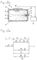
- Figure 2a illustrates schematically a rectangular package made of a layered material, one of the layers being electrically conductive.
- Figure 2b illustrates the equivalent electric circuit of the total measured impedance in figure 2a.
- Figure 2c illustrates schematically the field lines between the first and second electrodes.
- Figure 1a illustrates schematically a rectangular package 10 comprising a front wall 11, a back wall 12, a bottom wall 13, a top wall 14 and two side walls 15 and 16.
- Figure 1c illustrates a cross section through said package.
- a first electrode 17 is positioned adjacent to the inner surface of the back wall 15 and a second electrode 18 is positioned adjacent to the outer surface of the front wall 11.
- the electrode 18 is connected to an impedance measuring and analyzing circuit 20 through a line 24.
- the electrode 17 is first connected to a terminal 22 on the outer surface of the back wall 12 through a conducting element 21 extending fluid tight through said wall 12.
- a further line 25 is connected between said terminal 22 and the impedance measuring and analyzing circuit 20.
- Such circuits are commercially available (for example the instrument model HP4194A manufacturing by Hewlett Packard Inc.) and therefore a detailed description of these instruments is considered superfluous.
- Figure 1b illustrates an equivalent electric circuit of the total measured impedance in figure 1a.
- Each impedance can be represented by a combination of a resistor and a capacitor as for instance indicated in figure 1b by R1, C1; Rx, Cx.
- Figure 1c indicates schematically the extension of the field lines between the relatively small first electrode 17 and the relatively large second electrode 18. As shown the field lines are highly concentrated near the first electrode 17
- the system is calibrated by performing one or more measurements with non-contaminated fluid at one or more preselected measuring frequencies. Carefully selecting a frequency is important because the various impedances are more or less frequency dependent. If because of microbiological contamination the value of Zx changes from the non-contaminated reference situation, the analyzing instrument 20 will compare the changed value with the reference value and indicate such variation. In case a rather simple instrument 20 is used the comparison between the "non-contaminated" reference value and the "contaminated" value can of course be performed manually.
- Figure 2a illustrates an application of the method according to the invention with a package 30 of which the wall comprises a layered structure consisting of outer layer(s) 31 of insulating material, an electrically conductive layer 32, preferably of metal such as aluminium, and inner insulating layer(s) 33.
- the package is made of an elongated strip of layered material by bending and folding and the resulting seam in the top wall is clearly illustrated in figure 2a.
- the construction of packages of this type is considered to be known to the expert in this field and will therefore not be described in detail.
- a first electrode 37 is positioned adjacent the inner surface of the right wall 40 of the package.
- the second electrode 38 is positioned adjacent the outer surface of the top wall 41.
- the actual position of the second electrode and also the size thereof are not important because the conductive layer 32 forms an equipotential plane screening the inner volume from the outside world.
- a second electrode of any size anywhere adjacent to the outer surface of the package will suffice.
- the first electrode 37 Because of the presence of the metal layer 32 the first electrode 37 has to be positioned adjacent to the inner surface of the wall 40. The actual position of the first electrode doesn't matter as long as the first electrode is inside the screen formed by the conductive layer 32.
- the first electrode 37 is electrically connected to a terminal 34 on the outside surface of wall 40. Of course, measures are taken to avoid contact between the metal layer 32 and the combination of electrode 37, terminal 34, and the inter-connecting lead therebetween.
- the measuring and analysing circuit 20 is connected on the one hand to the terminal 34 and on the other hand to the second electrode 38.
- Figure 2b illustrates the equivalent electric circuit of the configuration in figure 2a.
- the presence of the conductive layer 32 has a number of advantages.
- the impedance Z2 is a fixed mainly capacitive impedance so that only Z3 and Z4 play a role in the actual measurement of Zx.
- Z4 is dependent on the dimensions of the first electrode.
- the impedance Z3 changes as the impedance Zx changes.
- the field line pattern illustrated in figure 2A This pattern shows a strong concentration of field lines near the first electrode 37. If Rx for some reason decreases from the reference value then the field line distribution will change such that the number of field lines near the first electrode 37 increases. The result thereof is that R3 increases. In other words a change in Rx leads to a change in R3 in the same sense so that in fact the change in Rx is "amplified".
- this system is calibrated by performing one or more measurements with non-contaminated fluid at one or more preselected measuring frequencies. If because of microbiological contamination the value of Zx changes from the non-contaminated reference situation, the analysing instrument 20 will compare the changed value with the reference value and indicate such variation. In case a rather simple instrument 20 is used the comparison between the "non-contaminated" reference value and the "contaminated” value can of course be performed manually.
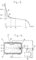
- Figure 3 illustrates how the resistive part Rx of the measured impedance Zx varies as function of the measuring frequency f used by the circuit 20. Normally an intermediate frequency between f1 and f2 (such as fa) is used. The curve in figure 3 shows a rather linear section between f1 and f2. Deviations from a reference value at a predetermined measuring frequency, for instance caused by an increasing number of microbiological entities, are clearly detectable and measurable.
- Figure 4 illustrates a modification 30' of the configuration shown in figure 2A. The differences between both figures are to be found in the embodiment of the second electrode and in the way the various electrodes can be connected to the measuring and analysing circuit 20.
- the second electrode 38 is divided in two electrode bodies 38a and 38b, each preferably of the same shape and dimensions. Furthermore said dimensions are preferably selected such that each electrode body covers approximately the whole surface of the respective bottom or top wall of the package 30'.
- a double switch Sa,Sb is added to the circuit 20.
- the circuit 20 In the shown condition (full lines) the circuit 20 is connected to the two electrode bodies 38a and 38b. In the other condition (dashed lines) the circuit 20 is connected to the first electrode and to two parallelled electrode bodies 38a, 38b. In this last condition the whole configuration functions exactly as described with reference to figure 2A.
- the two electrode bodies 38a and 38b are treated as separate electrodes by means of which the impedance therebetween is measured.
- the conductive layer 32 forms an equipotential plane in fact the impedance of the outer layer 31 is measured.
- the measured value changes significant if there is a leak through which the layer becomes wet. In that case the resistance R2 will become smaller and the capacitor C2 will become larger so that the total impedance Z2 will become significantly smaller.
- this measurement provide an indication of a volume change. If because of contamination gas is formed inside the package resulting in an increase of the total volume and the measurement is carried out always with the same distance between the electrode bodies 38a and 38b, then the increase in volume will result into a higher pressure in the wall of the package. Said higher pressure results into a change in Z2 which is clearly detectable.
- a corresponding embodiment 30'' is illustrated schematically in figure 5.
- the conductive layer is in a suitable manner connected to terminal 44 on the surface of the top wall 41, and the terminal 44 is connected to the measuring instrument 20.
- Figure 6 illustrates another embodiment of a package, in this case a cylindrical package having the cylindrical wall 50, the back end wall 52 and the front end wall 54.
- a first electrode 56 is positioned adjacent to the front end wall 54 and two electrode bodies 58a and 58b, together forming the second electrode, are positioned adjacent to the cylindrical wall 52 opposite each other and in symmetrical relation to the first electrode 56.
- Both electrode bodies 58a and 58b are connected in parallel to the conductivity measuring and analysing circuit 20.
- the circuit 20 is also connected to the first electrode 56.
Landscapes
- Chemical & Material Sciences (AREA)
- Health & Medical Sciences (AREA)
- Life Sciences & Earth Sciences (AREA)
- General Health & Medical Sciences (AREA)
- Immunology (AREA)
- Pathology (AREA)
- Analytical Chemistry (AREA)
- Biochemistry (AREA)
- Physics & Mathematics (AREA)
- General Physics & Mathematics (AREA)
- Chemical Kinetics & Catalysis (AREA)
- Electrochemistry (AREA)
- Engineering & Computer Science (AREA)
- Food Science & Technology (AREA)
- Medicinal Chemistry (AREA)
- Investigating Or Analyzing Materials By The Use Of Electric Means (AREA)
- Measurement Of Resistance Or Impedance (AREA)
- Examining Or Testing Airtightness (AREA)
Priority Applications (3)
| Application Number | Priority Date | Filing Date | Title |
|---|---|---|---|
| EP96201096A EP0803728A1 (de) | 1996-04-24 | 1996-04-24 | Verfahren zum Messen der Leitfähigkeit von Flüssigkeiten |
| AU19095/97A AU1909597A (en) | 1996-04-24 | 1997-04-23 | Method for measuring the conductivity of fluids |
| JP10781997A JPH1082754A (ja) | 1996-04-24 | 1997-04-24 | 流体の導電度測定方法 |
Applications Claiming Priority (1)
| Application Number | Priority Date | Filing Date | Title |
|---|---|---|---|
| EP96201096A EP0803728A1 (de) | 1996-04-24 | 1996-04-24 | Verfahren zum Messen der Leitfähigkeit von Flüssigkeiten |
Publications (1)
| Publication Number | Publication Date |
|---|---|
| EP0803728A1 true EP0803728A1 (de) | 1997-10-29 |
Family
ID=8223909
Family Applications (1)
| Application Number | Title | Priority Date | Filing Date |
|---|---|---|---|
| EP96201096A Withdrawn EP0803728A1 (de) | 1996-04-24 | 1996-04-24 | Verfahren zum Messen der Leitfähigkeit von Flüssigkeiten |
Country Status (3)
| Country | Link |
|---|---|
| EP (1) | EP0803728A1 (de) |
| JP (1) | JPH1082754A (de) |
| AU (1) | AU1909597A (de) |
Cited By (3)
| Publication number | Priority date | Publication date | Assignee | Title |
|---|---|---|---|---|
| WO2004096974A3 (de) * | 2003-05-02 | 2005-06-09 | Lmb Technologie Gmbh | Verfahren und vorrichtung zur schnellen bestimmung einer bakteriellen belastung in blut und blutprodukten |
| EP1999446A4 (de) * | 2006-03-22 | 2011-12-14 | Atmi Packaging Inc | Vorrichtung und verfahren zur leckage-erkennung in biologischen bearbeitungsbeuteln |
| US11397159B1 (en) | 2018-08-31 | 2022-07-26 | Byte Nutrition Science Incorporated | Systems, devices and methods for analyzing constituents of a material under test |
Families Citing this family (2)
| Publication number | Priority date | Publication date | Assignee | Title |
|---|---|---|---|---|
| JP7390180B2 (ja) * | 2019-12-24 | 2023-12-01 | 日置電機株式会社 | 測定装置及び測定方法 |
| JP7648087B2 (ja) * | 2021-06-15 | 2025-03-18 | 東洋製罐株式会社 | 容器詰め食品の状態を評価する装置及び方法 |
Citations (3)
| Publication number | Priority date | Publication date | Assignee | Title |
|---|---|---|---|---|
| GB1070833A (en) * | 1964-09-24 | 1967-06-07 | George Kent Stroud Ltd | Improvements in or relating to electrode assemblies |
| EP0036274A2 (de) * | 1980-03-08 | 1981-09-23 | Japan Tectron Instruments Corporation | Verfahren zur Überwachung von Mikroorganismen und Nährboden |
| JPH0518925A (ja) * | 1991-07-08 | 1993-01-26 | Toto Ltd | 密封内容物の腐敗判定方法及び腐敗判定センサ |
-
1996
- 1996-04-24 EP EP96201096A patent/EP0803728A1/de not_active Withdrawn
-
1997
- 1997-04-23 AU AU19095/97A patent/AU1909597A/en not_active Abandoned
- 1997-04-24 JP JP10781997A patent/JPH1082754A/ja active Pending
Patent Citations (3)
| Publication number | Priority date | Publication date | Assignee | Title |
|---|---|---|---|---|
| GB1070833A (en) * | 1964-09-24 | 1967-06-07 | George Kent Stroud Ltd | Improvements in or relating to electrode assemblies |
| EP0036274A2 (de) * | 1980-03-08 | 1981-09-23 | Japan Tectron Instruments Corporation | Verfahren zur Überwachung von Mikroorganismen und Nährboden |
| JPH0518925A (ja) * | 1991-07-08 | 1993-01-26 | Toto Ltd | 密封内容物の腐敗判定方法及び腐敗判定センサ |
Non-Patent Citations (1)
| Title |
|---|
| PATENT ABSTRACTS OF JAPAN vol. 17, no. 290 (P - 1549) 3 June 1993 (1993-06-03) * |
Cited By (3)
| Publication number | Priority date | Publication date | Assignee | Title |
|---|---|---|---|---|
| WO2004096974A3 (de) * | 2003-05-02 | 2005-06-09 | Lmb Technologie Gmbh | Verfahren und vorrichtung zur schnellen bestimmung einer bakteriellen belastung in blut und blutprodukten |
| EP1999446A4 (de) * | 2006-03-22 | 2011-12-14 | Atmi Packaging Inc | Vorrichtung und verfahren zur leckage-erkennung in biologischen bearbeitungsbeuteln |
| US11397159B1 (en) | 2018-08-31 | 2022-07-26 | Byte Nutrition Science Incorporated | Systems, devices and methods for analyzing constituents of a material under test |
Also Published As
| Publication number | Publication date |
|---|---|
| AU1909597A (en) | 1997-10-30 |
| JPH1082754A (ja) | 1998-03-31 |
Similar Documents
| Publication | Publication Date | Title |
|---|---|---|
| US5546005A (en) | Guarded capacitance probe and related measurement circuit | |
| JP5757798B2 (ja) | 容器内の充填媒質の非侵襲性容量式充填レベル測定装置および方法 | |
| US11360040B2 (en) | Devices and methods for capacitive foam detection in liquid containers | |
| US6894502B2 (en) | pH sensor with internal solution ground | |
| RU2115935C1 (ru) | Способ бесконтактного измерения диэлектрической постоянной диэлектрического вещества | |
| US20120130663A1 (en) | On-line diagnostic method for health monitoring of a transformer | |
| US6844742B2 (en) | Method and apparatus for measuring chemical concentration in a fluid | |
| JPH05340789A (ja) | 分析ユニット用液体移送装置 | |
| US20100045309A1 (en) | Method and apparatus for measuring fluid properties, including ph | |
| US4544880A (en) | Microwave probe for measurement of dielectric constants | |
| AU738753B2 (en) | Leak test process for closed receptacles, test chamber, test set-up and testing device for this process | |
| WO2000049384A1 (en) | System and method for determining a density of a fluid | |
| US5489849A (en) | High accuracy calibration-free electrical parameter measurements using differential measurement with respect to immersion depth | |
| JPH035863Y2 (de) | ||
| EP0803728A1 (de) | Verfahren zum Messen der Leitfähigkeit von Flüssigkeiten | |
| US4924173A (en) | Shielded capacitance standard | |
| JP7071723B2 (ja) | 複素誘電率測定用回路、複素誘電率測定装置及び複素誘電率の測定方法 | |
| US4543823A (en) | Microwave probe for detecting oil level | |
| CN213457326U (zh) | 一种绝缘电阻检测仪器的接触不良测试系统 | |
| CN100578208C (zh) | 被干燥物含水率的无损伤测量方法 | |
| US6498566B1 (en) | Method for measuring fluid level | |
| JP2003523517A (ja) | 潤滑油中の粒子特性を測定する測定方法及びその装置 | |
| US7030631B1 (en) | Method and apparatus for monitoring and determining the moisture content of a substance in a container | |
| US7205779B2 (en) | Apparatus and method for monitoring and determining the moisture content in elastomer materials | |
| US6497144B1 (en) | Method for measuring fluid level |
Legal Events
| Date | Code | Title | Description |
|---|---|---|---|
| PUAI | Public reference made under article 153(3) epc to a published international application that has entered the european phase |
Free format text: ORIGINAL CODE: 0009012 |
|
| AK | Designated contracting states |
Kind code of ref document: A1 Designated state(s): AT BE CH DE DK ES FI FR GB GR IE IT LI LU MC NL PT SE |
|
| STAA | Information on the status of an ep patent application or granted ep patent |
Free format text: STATUS: THE APPLICATION IS DEEMED TO BE WITHDRAWN |
|
| 18D | Application deemed to be withdrawn |
Effective date: 19980430 |