EP1633013B1 - Lithium secondary battery and method for producing same - Google Patents
Lithium secondary battery and method for producing same Download PDFInfo
- Publication number
- EP1633013B1 EP1633013B1 EP04745547A EP04745547A EP1633013B1 EP 1633013 B1 EP1633013 B1 EP 1633013B1 EP 04745547 A EP04745547 A EP 04745547A EP 04745547 A EP04745547 A EP 04745547A EP 1633013 B1 EP1633013 B1 EP 1633013B1
- Authority
- EP
- European Patent Office
- Prior art keywords
- rechargeable lithium
- lithium battery
- nonaqueous electrolyte
- recited
- thin film
- Prior art date
- Legal status (The legal status is an assumption and is not a legal conclusion. Google has not performed a legal analysis and makes no representation as to the accuracy of the status listed.)
- Expired - Lifetime
Links
- 229910052744 lithium Inorganic materials 0.000 title claims abstract description 96
- WHXSMMKQMYFTQS-UHFFFAOYSA-N Lithium Chemical compound [Li] WHXSMMKQMYFTQS-UHFFFAOYSA-N 0.000 title claims abstract description 95
- 238000004519 manufacturing process Methods 0.000 title description 24
- CURLTUGMZLYLDI-UHFFFAOYSA-N Carbon dioxide Chemical compound O=C=O CURLTUGMZLYLDI-UHFFFAOYSA-N 0.000 claims abstract description 258
- 239000011255 nonaqueous electrolyte Substances 0.000 claims abstract description 168
- 229910002092 carbon dioxide Inorganic materials 0.000 claims abstract description 137
- 239000010409 thin film Substances 0.000 claims abstract description 133
- 239000001569 carbon dioxide Substances 0.000 claims abstract description 119
- 229910052710 silicon Inorganic materials 0.000 claims abstract description 41
- 239000010703 silicon Substances 0.000 claims abstract description 40
- OIFBSDVPJOWBCH-UHFFFAOYSA-N Diethyl carbonate Chemical compound CCOC(=O)OCC OIFBSDVPJOWBCH-UHFFFAOYSA-N 0.000 claims description 56
- KMTRUDSVKNLOMY-UHFFFAOYSA-N Ethylene carbonate Chemical compound O=C1OCCO1 KMTRUDSVKNLOMY-UHFFFAOYSA-N 0.000 claims description 47
- 238000000034 method Methods 0.000 claims description 47
- 238000000151 deposition Methods 0.000 claims description 34
- 150000005676 cyclic carbonates Chemical class 0.000 claims description 33
- VAYTZRYEBVHVLE-UHFFFAOYSA-N 1,3-dioxol-2-one Chemical compound O=C1OC=CO1 VAYTZRYEBVHVLE-UHFFFAOYSA-N 0.000 claims description 31
- 239000010949 copper Substances 0.000 claims description 23
- 239000012046 mixed solvent Substances 0.000 claims description 23
- 230000008569 process Effects 0.000 claims description 23
- 229910000881 Cu alloy Inorganic materials 0.000 claims description 22
- 239000012298 atmosphere Substances 0.000 claims description 20
- 239000011888 foil Substances 0.000 claims description 18
- 238000004544 sputter deposition Methods 0.000 claims description 13
- 150000005678 chain carbonates Chemical class 0.000 claims description 12
- 229910052802 copper Inorganic materials 0.000 claims description 12
- RYGMFSIKBFXOCR-UHFFFAOYSA-N Copper Chemical compound [Cu] RYGMFSIKBFXOCR-UHFFFAOYSA-N 0.000 claims description 10
- YCKRFDGAMUMZLT-UHFFFAOYSA-N Fluorine atom Chemical compound [F] YCKRFDGAMUMZLT-UHFFFAOYSA-N 0.000 claims description 10
- XEEYBQQBJWHFJM-UHFFFAOYSA-N Iron Chemical compound [Fe] XEEYBQQBJWHFJM-UHFFFAOYSA-N 0.000 claims description 10
- 238000001704 evaporation Methods 0.000 claims description 10
- 239000011737 fluorine Substances 0.000 claims description 10
- 229910052731 fluorine Inorganic materials 0.000 claims description 10
- 230000008020 evaporation Effects 0.000 claims description 9
- 229910052698 phosphorus Inorganic materials 0.000 claims description 7
- 229910052787 antimony Inorganic materials 0.000 claims description 6
- 229910052785 arsenic Inorganic materials 0.000 claims description 6
- 229910052796 boron Inorganic materials 0.000 claims description 6
- 229910052733 gallium Inorganic materials 0.000 claims description 6
- 229910052738 indium Inorganic materials 0.000 claims description 6
- MHCFAGZWMAWTNR-UHFFFAOYSA-M lithium perchlorate Chemical compound [Li+].[O-]Cl(=O)(=O)=O MHCFAGZWMAWTNR-UHFFFAOYSA-M 0.000 claims description 6
- 229910001486 lithium perchlorate Inorganic materials 0.000 claims description 6
- RUOJZAUFBMNUDX-UHFFFAOYSA-N propylene carbonate Chemical compound CC1COC(=O)O1 RUOJZAUFBMNUDX-UHFFFAOYSA-N 0.000 claims description 6
- 229910013098 LiBF2 Inorganic materials 0.000 claims description 5
- 150000001875 compounds Chemical class 0.000 claims description 5
- 229910052742 iron Inorganic materials 0.000 claims description 5
- RIUWBIIVUYSTCN-UHFFFAOYSA-N trilithium borate Chemical class [Li+].[Li+].[Li+].[O-]B([O-])[O-] RIUWBIIVUYSTCN-UHFFFAOYSA-N 0.000 claims description 5
- 229910016833 LiXFy Inorganic materials 0.000 claims description 3
- 238000000137 annealing Methods 0.000 claims description 3
- 238000005229 chemical vapour deposition Methods 0.000 claims description 3
- 229910017052 cobalt Inorganic materials 0.000 claims description 3
- 239000010941 cobalt Substances 0.000 claims description 3
- GUTLYIVDDKVIGB-UHFFFAOYSA-N cobalt atom Chemical compound [Co] GUTLYIVDDKVIGB-UHFFFAOYSA-N 0.000 claims description 3
- 239000002994 raw material Substances 0.000 claims description 3
- 239000012808 vapor phase Substances 0.000 claims description 3
- 229910013149 LiN(CmF2m+1SO2)(CnF2n+1SO2) Inorganic materials 0.000 claims description 2
- 230000001747 exhibiting effect Effects 0.000 claims 2
- 229920001296 polysiloxane Polymers 0.000 claims 2
- 229910052797 bismuth Inorganic materials 0.000 claims 1
- 238000007664 blowing Methods 0.000 claims 1
- 239000002344 surface layer Substances 0.000 claims 1
- XUIMIQQOPSSXEZ-UHFFFAOYSA-N Silicon Chemical compound [Si] XUIMIQQOPSSXEZ-UHFFFAOYSA-N 0.000 abstract description 39
- 229910021417 amorphous silicon Inorganic materials 0.000 abstract description 3
- 238000002474 experimental method Methods 0.000 description 36
- 238000002360 preparation method Methods 0.000 description 32
- 230000014759 maintenance of location Effects 0.000 description 29
- 230000008021 deposition Effects 0.000 description 26
- 239000007789 gas Substances 0.000 description 24
- 239000011149 active material Substances 0.000 description 23
- 239000010408 film Substances 0.000 description 22
- 238000012360 testing method Methods 0.000 description 22
- 229910001290 LiPF6 Inorganic materials 0.000 description 18
- 239000002904 solvent Substances 0.000 description 15
- 230000008859 change Effects 0.000 description 14
- 239000007774 positive electrode material Substances 0.000 description 12
- JBTWLSYIZRCDFO-UHFFFAOYSA-N ethyl methyl carbonate Chemical compound CCOC(=O)OC JBTWLSYIZRCDFO-UHFFFAOYSA-N 0.000 description 10
- 239000000463 material Substances 0.000 description 10
- 239000007773 negative electrode material Substances 0.000 description 10
- 239000000243 solution Substances 0.000 description 10
- ZZXUZKXVROWEIF-UHFFFAOYSA-N 1,2-butylene carbonate Chemical compound CCC1COC(=O)O1 ZZXUZKXVROWEIF-UHFFFAOYSA-N 0.000 description 9
- 229910045601 alloy Inorganic materials 0.000 description 9
- 239000000956 alloy Substances 0.000 description 9
- 229910052782 aluminium Inorganic materials 0.000 description 9
- 229940021013 electrolyte solution Drugs 0.000 description 9
- 150000002500 ions Chemical class 0.000 description 9
- 239000000203 mixture Substances 0.000 description 9
- XAGFODPZIPBFFR-UHFFFAOYSA-N aluminium Chemical compound [Al] XAGFODPZIPBFFR-UHFFFAOYSA-N 0.000 description 8
- 230000015572 biosynthetic process Effects 0.000 description 8
- 210000004027 cell Anatomy 0.000 description 8
- 230000001351 cycling effect Effects 0.000 description 8
- 230000005855 radiation Effects 0.000 description 8
- 238000001228 spectrum Methods 0.000 description 8
- 239000000758 substrate Substances 0.000 description 8
- IEJIGPNLZYLLBP-UHFFFAOYSA-N dimethyl carbonate Chemical compound COC(=O)OC IEJIGPNLZYLLBP-UHFFFAOYSA-N 0.000 description 7
- 239000002002 slurry Substances 0.000 description 7
- 238000005011 time of flight secondary ion mass spectroscopy Methods 0.000 description 7
- XKRFYHLGVUSROY-UHFFFAOYSA-N Argon Chemical compound [Ar] XKRFYHLGVUSROY-UHFFFAOYSA-N 0.000 description 6
- OKTJSMMVPCPJKN-UHFFFAOYSA-N Carbon Chemical compound [C] OKTJSMMVPCPJKN-UHFFFAOYSA-N 0.000 description 6
- QVGXLLKOCUKJST-UHFFFAOYSA-N atomic oxygen Chemical compound [O] QVGXLLKOCUKJST-UHFFFAOYSA-N 0.000 description 6
- 230000000052 comparative effect Effects 0.000 description 6
- 239000001301 oxygen Substances 0.000 description 6
- 229910052760 oxygen Inorganic materials 0.000 description 6
- 238000002042 time-of-flight secondary ion mass spectrometry Methods 0.000 description 6
- 229910052726 zirconium Inorganic materials 0.000 description 6
- 238000002441 X-ray diffraction Methods 0.000 description 5
- 239000011230 binding agent Substances 0.000 description 5
- XTYUEDCPRIMJNG-UHFFFAOYSA-N copper zirconium Chemical compound [Cu].[Zr] XTYUEDCPRIMJNG-UHFFFAOYSA-N 0.000 description 5
- 239000008151 electrolyte solution Substances 0.000 description 5
- 238000000313 electron-beam-induced deposition Methods 0.000 description 5
- 229910001369 Brass Inorganic materials 0.000 description 4
- SECXISVLQFMRJM-UHFFFAOYSA-N N-Methylpyrrolidone Chemical compound CN1CCCC1=O SECXISVLQFMRJM-UHFFFAOYSA-N 0.000 description 4
- 229910018598 Si-Co Inorganic materials 0.000 description 4
- 229910018619 Si-Fe Inorganic materials 0.000 description 4
- 229910008453 Si—Co Inorganic materials 0.000 description 4
- 229910008289 Si—Fe Inorganic materials 0.000 description 4
- -1 Slight Amounts of Co Inorganic materials 0.000 description 4
- 238000003917 TEM image Methods 0.000 description 4
- QCWXUUIWCKQGHC-UHFFFAOYSA-N Zirconium Chemical compound [Zr] QCWXUUIWCKQGHC-UHFFFAOYSA-N 0.000 description 4
- 239000012300 argon atmosphere Substances 0.000 description 4
- 239000010951 brass Substances 0.000 description 4
- 229910052799 carbon Inorganic materials 0.000 description 4
- 238000010894 electron beam technology Methods 0.000 description 4
- 238000007254 oxidation reaction Methods 0.000 description 4
- 239000011701 zinc Substances 0.000 description 4
- 229910032387 LiCoO2 Inorganic materials 0.000 description 3
- HBBGRARXTFLTSG-UHFFFAOYSA-N Lithium ion Chemical compound [Li+] HBBGRARXTFLTSG-UHFFFAOYSA-N 0.000 description 3
- 229910000676 Si alloy Inorganic materials 0.000 description 3
- 239000007864 aqueous solution Substances 0.000 description 3
- 229910052786 argon Inorganic materials 0.000 description 3
- 229910021383 artificial graphite Inorganic materials 0.000 description 3
- 238000006243 chemical reaction Methods 0.000 description 3
- AIOWANYIHSOXQY-UHFFFAOYSA-N cobalt silicon Chemical compound [Si].[Co] AIOWANYIHSOXQY-UHFFFAOYSA-N 0.000 description 3
- 239000004020 conductor Substances 0.000 description 3
- 230000009977 dual effect Effects 0.000 description 3
- 230000000694 effects Effects 0.000 description 3
- 239000003792 electrolyte Substances 0.000 description 3
- 230000006872 improvement Effects 0.000 description 3
- 229910001416 lithium ion Inorganic materials 0.000 description 3
- 229910052759 nickel Inorganic materials 0.000 description 3
- 230000003647 oxidation Effects 0.000 description 3
- 210000002381 plasma Anatomy 0.000 description 3
- 239000011148 porous material Substances 0.000 description 3
- 229910052718 tin Inorganic materials 0.000 description 3
- 229910000906 Bronze Inorganic materials 0.000 description 2
- 229910000531 Co alloy Inorganic materials 0.000 description 2
- RTZKZFJDLAIYFH-UHFFFAOYSA-N Diethyl ether Chemical compound CCOCC RTZKZFJDLAIYFH-UHFFFAOYSA-N 0.000 description 2
- XTHFKEDIFFGKHM-UHFFFAOYSA-N Dimethoxyethane Chemical compound COCCOC XTHFKEDIFFGKHM-UHFFFAOYSA-N 0.000 description 2
- 238000005275 alloying Methods 0.000 description 2
- 239000010974 bronze Substances 0.000 description 2
- 235000011089 carbon dioxide Nutrition 0.000 description 2
- 239000003575 carbonaceous material Substances 0.000 description 2
- KUNSUQLRTQLHQQ-UHFFFAOYSA-N copper tin Chemical compound [Cu].[Sn] KUNSUQLRTQLHQQ-UHFFFAOYSA-N 0.000 description 2
- 125000004122 cyclic group Chemical group 0.000 description 2
- 238000009831 deintercalation Methods 0.000 description 2
- 238000005566 electron beam evaporation Methods 0.000 description 2
- 238000002149 energy-dispersive X-ray emission spectroscopy Methods 0.000 description 2
- 238000009830 intercalation Methods 0.000 description 2
- 150000002642 lithium compounds Chemical class 0.000 description 2
- NUJOXMJBOLGQSY-UHFFFAOYSA-N manganese dioxide Chemical compound O=[Mn]=O NUJOXMJBOLGQSY-UHFFFAOYSA-N 0.000 description 2
- 238000005259 measurement Methods 0.000 description 2
- 239000005518 polymer electrolyte Substances 0.000 description 2
- 229920001343 polytetrafluoroethylene Polymers 0.000 description 2
- 239000004810 polytetrafluoroethylene Substances 0.000 description 2
- 239000000843 powder Substances 0.000 description 2
- 230000009467 reduction Effects 0.000 description 2
- 230000000979 retarding effect Effects 0.000 description 2
- 239000002409 silicon-based active material Substances 0.000 description 2
- 239000010935 stainless steel Substances 0.000 description 2
- 229910001220 stainless steel Inorganic materials 0.000 description 2
- 238000005211 surface analysis Methods 0.000 description 2
- 230000003746 surface roughness Effects 0.000 description 2
- 239000002562 thickening agent Substances 0.000 description 2
- 238000012546 transfer Methods 0.000 description 2
- 229910000314 transition metal oxide Inorganic materials 0.000 description 2
- 229910052725 zinc Inorganic materials 0.000 description 2
- LZDKZFUFMNSQCJ-UHFFFAOYSA-N 1,2-diethoxyethane Chemical compound CCOCCOCC LZDKZFUFMNSQCJ-UHFFFAOYSA-N 0.000 description 1
- BJWMSGRKJIOCNR-UHFFFAOYSA-N 4-ethenyl-1,3-dioxolan-2-one Chemical compound C=CC1COC(=O)O1 BJWMSGRKJIOCNR-UHFFFAOYSA-N 0.000 description 1
- 229920002134 Carboxymethyl cellulose Polymers 0.000 description 1
- 229910000570 Cupronickel Inorganic materials 0.000 description 1
- 229910000640 Fe alloy Inorganic materials 0.000 description 1
- 229910010820 Li2B10Cl10 Inorganic materials 0.000 description 1
- 229910010903 Li2B12Cl12 Inorganic materials 0.000 description 1
- 229910000552 LiCF3SO3 Inorganic materials 0.000 description 1
- 229910013595 LiCo0.5Ni0.5O2 Inorganic materials 0.000 description 1
- 229910002993 LiMnO2 Inorganic materials 0.000 description 1
- 229910011669 LiNi0.7Co0.2Mn0.1O2 Inorganic materials 0.000 description 1
- 229910003005 LiNiO2 Inorganic materials 0.000 description 1
- 229910002097 Lithium manganese(III,IV) oxide Inorganic materials 0.000 description 1
- 239000002033 PVDF binder Substances 0.000 description 1
- OAICVXFJPJFONN-UHFFFAOYSA-N Phosphorus Chemical compound [P] OAICVXFJPJFONN-UHFFFAOYSA-N 0.000 description 1
- 229920003171 Poly (ethylene oxide) Polymers 0.000 description 1
- 239000004698 Polyethylene Substances 0.000 description 1
- 229910008341 Si-Zr Inorganic materials 0.000 description 1
- 229910006776 Si—Zn Inorganic materials 0.000 description 1
- 229910006682 Si—Zr Inorganic materials 0.000 description 1
- 238000004833 X-ray photoelectron spectroscopy Methods 0.000 description 1
- HCHKCACWOHOZIP-UHFFFAOYSA-N Zinc Chemical compound [Zn] HCHKCACWOHOZIP-UHFFFAOYSA-N 0.000 description 1
- 238000010521 absorption reaction Methods 0.000 description 1
- 239000013543 active substance Substances 0.000 description 1
- DMFGNRRURHSENX-UHFFFAOYSA-N beryllium copper Chemical compound [Be].[Cu] DMFGNRRURHSENX-UHFFFAOYSA-N 0.000 description 1
- 230000005540 biological transmission Effects 0.000 description 1
- 238000003490 calendering Methods 0.000 description 1
- 150000004649 carbonic acid derivatives Chemical class 0.000 description 1
- ZJRWDIJRKKXMNW-UHFFFAOYSA-N carbonic acid;cobalt Chemical compound [Co].OC(O)=O ZJRWDIJRKKXMNW-UHFFFAOYSA-N 0.000 description 1
- 239000001768 carboxy methyl cellulose Substances 0.000 description 1
- 235000010948 carboxy methyl cellulose Nutrition 0.000 description 1
- 239000008112 carboxymethyl-cellulose Substances 0.000 description 1
- 229910052804 chromium Inorganic materials 0.000 description 1
- ZTXONRUJVYXVTJ-UHFFFAOYSA-N chromium copper Chemical compound [Cr][Cu][Cr] ZTXONRUJVYXVTJ-UHFFFAOYSA-N 0.000 description 1
- 229910000001 cobalt(II) carbonate Inorganic materials 0.000 description 1
- 239000012141 concentrate Substances 0.000 description 1
- 238000010280 constant potential charging Methods 0.000 description 1
- 239000011889 copper foil Substances 0.000 description 1
- IUYOGGFTLHZHEG-UHFFFAOYSA-N copper titanium Chemical compound [Ti].[Cu] IUYOGGFTLHZHEG-UHFFFAOYSA-N 0.000 description 1
- 239000013078 crystal Substances 0.000 description 1
- 230000006378 damage Effects 0.000 description 1
- 230000007423 decrease Effects 0.000 description 1
- 230000006866 deterioration Effects 0.000 description 1
- UREBDLICKHMUKA-CXSFZGCWSA-N dexamethasone Chemical compound C1CC2=CC(=O)C=C[C@]2(C)[C@]2(F)[C@@H]1[C@@H]1C[C@@H](C)[C@@](C(=O)CO)(O)[C@@]1(C)C[C@@H]2O UREBDLICKHMUKA-CXSFZGCWSA-N 0.000 description 1
- 239000011267 electrode slurry Substances 0.000 description 1
- 150000003949 imides Chemical class 0.000 description 1
- 239000012535 impurity Substances 0.000 description 1
- 238000010348 incorporation Methods 0.000 description 1
- 238000003780 insertion Methods 0.000 description 1
- 230000037431 insertion Effects 0.000 description 1
- 238000010884 ion-beam technique Methods 0.000 description 1
- XWHPIFXRKKHEKR-UHFFFAOYSA-N iron silicon Chemical compound [Si].[Fe] XWHPIFXRKKHEKR-UHFFFAOYSA-N 0.000 description 1
- 230000001788 irregular Effects 0.000 description 1
- 230000002427 irreversible effect Effects 0.000 description 1
- 230000000670 limiting effect Effects 0.000 description 1
- XGZVUEUWXADBQD-UHFFFAOYSA-L lithium carbonate Chemical compound [Li+].[Li+].[O-]C([O-])=O XGZVUEUWXADBQD-UHFFFAOYSA-L 0.000 description 1
- 229910052808 lithium carbonate Inorganic materials 0.000 description 1
- 229910001540 lithium hexafluoroarsenate(V) Inorganic materials 0.000 description 1
- 229910001496 lithium tetrafluoroborate Inorganic materials 0.000 description 1
- ACFSQHQYDZIPRL-UHFFFAOYSA-N lithium;bis(1,1,2,2,2-pentafluoroethylsulfonyl)azanide Chemical compound [Li+].FC(F)(F)C(F)(F)S(=O)(=O)[N-]S(=O)(=O)C(F)(F)C(F)(F)F ACFSQHQYDZIPRL-UHFFFAOYSA-N 0.000 description 1
- QSZMZKBZAYQGRS-UHFFFAOYSA-N lithium;bis(trifluoromethylsulfonyl)azanide Chemical compound [Li+].FC(F)(F)S(=O)(=O)[N-]S(=O)(=O)C(F)(F)F QSZMZKBZAYQGRS-UHFFFAOYSA-N 0.000 description 1
- 229910052748 manganese Inorganic materials 0.000 description 1
- 229910044991 metal oxide Inorganic materials 0.000 description 1
- 150000004706 metal oxides Chemical class 0.000 description 1
- LGRLWUINFJPLSH-UHFFFAOYSA-N methanide Chemical compound [CH3-] LGRLWUINFJPLSH-UHFFFAOYSA-N 0.000 description 1
- 238000012986 modification Methods 0.000 description 1
- 230000004048 modification Effects 0.000 description 1
- 239000004570 mortar (masonry) Substances 0.000 description 1
- 239000002245 particle Substances 0.000 description 1
- 230000002093 peripheral effect Effects 0.000 description 1
- 229920002239 polyacrylonitrile Polymers 0.000 description 1
- 239000004417 polycarbonate Substances 0.000 description 1
- 229920000515 polycarbonate Polymers 0.000 description 1
- 229920000573 polyethylene Polymers 0.000 description 1
- 229920002981 polyvinylidene fluoride Polymers 0.000 description 1
- 238000012545 processing Methods 0.000 description 1
- 230000001681 protective effect Effects 0.000 description 1
- 230000002829 reductive effect Effects 0.000 description 1
- 230000003252 repetitive effect Effects 0.000 description 1
- 230000002441 reversible effect Effects 0.000 description 1
- 238000000926 separation method Methods 0.000 description 1
- 229910021332 silicide Inorganic materials 0.000 description 1
- FVBUAEGBCNSCDD-UHFFFAOYSA-N silicide(4-) Chemical compound [Si-4] FVBUAEGBCNSCDD-UHFFFAOYSA-N 0.000 description 1
- 238000001179 sorption measurement Methods 0.000 description 1
- 239000007858 starting material Substances 0.000 description 1
- 238000003756 stirring Methods 0.000 description 1
- 238000003860 storage Methods 0.000 description 1
- 229920003048 styrene butadiene rubber Polymers 0.000 description 1
- 239000000126 substance Substances 0.000 description 1
- 238000000427 thin-film deposition Methods 0.000 description 1
- XLYOFNOQVPJJNP-UHFFFAOYSA-N water Substances O XLYOFNOQVPJJNP-UHFFFAOYSA-N 0.000 description 1
Images






Classifications
-
- H—ELECTRICITY
- H01—ELECTRIC ELEMENTS
- H01M—PROCESSES OR MEANS, e.g. BATTERIES, FOR THE DIRECT CONVERSION OF CHEMICAL ENERGY INTO ELECTRICAL ENERGY
- H01M10/00—Secondary cells; Manufacture thereof
- H01M10/05—Accumulators with non-aqueous electrolyte
- H01M10/052—Li-accumulators
-
- H—ELECTRICITY
- H01—ELECTRIC ELEMENTS
- H01M—PROCESSES OR MEANS, e.g. BATTERIES, FOR THE DIRECT CONVERSION OF CHEMICAL ENERGY INTO ELECTRICAL ENERGY
- H01M10/00—Secondary cells; Manufacture thereof
- H01M10/05—Accumulators with non-aqueous electrolyte
-
- H—ELECTRICITY
- H01—ELECTRIC ELEMENTS
- H01M—PROCESSES OR MEANS, e.g. BATTERIES, FOR THE DIRECT CONVERSION OF CHEMICAL ENERGY INTO ELECTRICAL ENERGY
- H01M10/00—Secondary cells; Manufacture thereof
- H01M10/05—Accumulators with non-aqueous electrolyte
- H01M10/056—Accumulators with non-aqueous electrolyte characterised by the materials used as electrolytes, e.g. mixed inorganic/organic electrolytes
- H01M10/0564—Accumulators with non-aqueous electrolyte characterised by the materials used as electrolytes, e.g. mixed inorganic/organic electrolytes the electrolyte being constituted of organic materials only
- H01M10/0566—Liquid materials
- H01M10/0567—Liquid materials characterised by the additives
-
- H—ELECTRICITY
- H01—ELECTRIC ELEMENTS
- H01M—PROCESSES OR MEANS, e.g. BATTERIES, FOR THE DIRECT CONVERSION OF CHEMICAL ENERGY INTO ELECTRICAL ENERGY
- H01M10/00—Secondary cells; Manufacture thereof
- H01M10/05—Accumulators with non-aqueous electrolyte
- H01M10/056—Accumulators with non-aqueous electrolyte characterised by the materials used as electrolytes, e.g. mixed inorganic/organic electrolytes
- H01M10/0564—Accumulators with non-aqueous electrolyte characterised by the materials used as electrolytes, e.g. mixed inorganic/organic electrolytes the electrolyte being constituted of organic materials only
- H01M10/0566—Liquid materials
- H01M10/0568—Liquid materials characterised by the solutes
-
- H—ELECTRICITY
- H01—ELECTRIC ELEMENTS
- H01M—PROCESSES OR MEANS, e.g. BATTERIES, FOR THE DIRECT CONVERSION OF CHEMICAL ENERGY INTO ELECTRICAL ENERGY
- H01M10/00—Secondary cells; Manufacture thereof
- H01M10/05—Accumulators with non-aqueous electrolyte
- H01M10/058—Construction or manufacture
- H01M10/0585—Construction or manufacture of accumulators having only flat construction elements, i.e. flat positive electrodes, flat negative electrodes and flat separators
-
- H—ELECTRICITY
- H01—ELECTRIC ELEMENTS
- H01M—PROCESSES OR MEANS, e.g. BATTERIES, FOR THE DIRECT CONVERSION OF CHEMICAL ENERGY INTO ELECTRICAL ENERGY
- H01M10/00—Secondary cells; Manufacture thereof
- H01M10/42—Methods or arrangements for servicing or maintenance of secondary cells or secondary half-cells
- H01M10/4235—Safety or regulating additives or arrangements in electrodes, separators or electrolyte
-
- H—ELECTRICITY
- H01—ELECTRIC ELEMENTS
- H01M—PROCESSES OR MEANS, e.g. BATTERIES, FOR THE DIRECT CONVERSION OF CHEMICAL ENERGY INTO ELECTRICAL ENERGY
- H01M4/00—Electrodes
- H01M4/02—Electrodes composed of, or comprising, active material
- H01M4/13—Electrodes for accumulators with non-aqueous electrolyte, e.g. for lithium-accumulators; Processes of manufacture thereof
- H01M4/134—Electrodes based on metals, Si or alloys
-
- H—ELECTRICITY
- H01—ELECTRIC ELEMENTS
- H01M—PROCESSES OR MEANS, e.g. BATTERIES, FOR THE DIRECT CONVERSION OF CHEMICAL ENERGY INTO ELECTRICAL ENERGY
- H01M4/00—Electrodes
- H01M4/02—Electrodes composed of, or comprising, active material
- H01M4/36—Selection of substances as active materials, active masses, active liquids
- H01M4/38—Selection of substances as active materials, active masses, active liquids of elements or alloys
-
- H—ELECTRICITY
- H01—ELECTRIC ELEMENTS
- H01M—PROCESSES OR MEANS, e.g. BATTERIES, FOR THE DIRECT CONVERSION OF CHEMICAL ENERGY INTO ELECTRICAL ENERGY
- H01M4/00—Electrodes
- H01M4/02—Electrodes composed of, or comprising, active material
- H01M4/36—Selection of substances as active materials, active masses, active liquids
- H01M4/38—Selection of substances as active materials, active masses, active liquids of elements or alloys
- H01M4/386—Silicon or alloys based on silicon
-
- H—ELECTRICITY
- H01—ELECTRIC ELEMENTS
- H01M—PROCESSES OR MEANS, e.g. BATTERIES, FOR THE DIRECT CONVERSION OF CHEMICAL ENERGY INTO ELECTRICAL ENERGY
- H01M4/00—Electrodes
- H01M4/02—Electrodes composed of, or comprising, active material
- H01M4/36—Selection of substances as active materials, active masses, active liquids
- H01M4/38—Selection of substances as active materials, active masses, active liquids of elements or alloys
- H01M4/40—Alloys based on alkali metals
-
- H—ELECTRICITY
- H01—ELECTRIC ELEMENTS
- H01M—PROCESSES OR MEANS, e.g. BATTERIES, FOR THE DIRECT CONVERSION OF CHEMICAL ENERGY INTO ELECTRICAL ENERGY
- H01M10/00—Secondary cells; Manufacture thereof
- H01M10/05—Accumulators with non-aqueous electrolyte
- H01M10/056—Accumulators with non-aqueous electrolyte characterised by the materials used as electrolytes, e.g. mixed inorganic/organic electrolytes
- H01M10/0564—Accumulators with non-aqueous electrolyte characterised by the materials used as electrolytes, e.g. mixed inorganic/organic electrolytes the electrolyte being constituted of organic materials only
- H01M10/0565—Polymeric materials, e.g. gel-type or solid-type
-
- H—ELECTRICITY
- H01—ELECTRIC ELEMENTS
- H01M—PROCESSES OR MEANS, e.g. BATTERIES, FOR THE DIRECT CONVERSION OF CHEMICAL ENERGY INTO ELECTRICAL ENERGY
- H01M10/00—Secondary cells; Manufacture thereof
- H01M10/05—Accumulators with non-aqueous electrolyte
- H01M10/056—Accumulators with non-aqueous electrolyte characterised by the materials used as electrolytes, e.g. mixed inorganic/organic electrolytes
- H01M10/0564—Accumulators with non-aqueous electrolyte characterised by the materials used as electrolytes, e.g. mixed inorganic/organic electrolytes the electrolyte being constituted of organic materials only
- H01M10/0566—Liquid materials
- H01M10/0569—Liquid materials characterised by the solvents
-
- H—ELECTRICITY
- H01—ELECTRIC ELEMENTS
- H01M—PROCESSES OR MEANS, e.g. BATTERIES, FOR THE DIRECT CONVERSION OF CHEMICAL ENERGY INTO ELECTRICAL ENERGY
- H01M2300/00—Electrolytes
- H01M2300/0017—Non-aqueous electrolytes
-
- H—ELECTRICITY
- H01—ELECTRIC ELEMENTS
- H01M—PROCESSES OR MEANS, e.g. BATTERIES, FOR THE DIRECT CONVERSION OF CHEMICAL ENERGY INTO ELECTRICAL ENERGY
- H01M4/00—Electrodes
- H01M4/02—Electrodes composed of, or comprising, active material
- H01M4/36—Selection of substances as active materials, active masses, active liquids
- H01M4/38—Selection of substances as active materials, active masses, active liquids of elements or alloys
- H01M4/40—Alloys based on alkali metals
- H01M4/405—Alloys based on lithium
-
- Y—GENERAL TAGGING OF NEW TECHNOLOGICAL DEVELOPMENTS; GENERAL TAGGING OF CROSS-SECTIONAL TECHNOLOGIES SPANNING OVER SEVERAL SECTIONS OF THE IPC; TECHNICAL SUBJECTS COVERED BY FORMER USPC CROSS-REFERENCE ART COLLECTIONS [XRACs] AND DIGESTS
- Y02—TECHNOLOGIES OR APPLICATIONS FOR MITIGATION OR ADAPTATION AGAINST CLIMATE CHANGE
- Y02E—REDUCTION OF GREENHOUSE GAS [GHG] EMISSIONS, RELATED TO ENERGY GENERATION, TRANSMISSION OR DISTRIBUTION
- Y02E60/00—Enabling technologies; Technologies with a potential or indirect contribution to GHG emissions mitigation
- Y02E60/10—Energy storage using batteries
-
- Y—GENERAL TAGGING OF NEW TECHNOLOGICAL DEVELOPMENTS; GENERAL TAGGING OF CROSS-SECTIONAL TECHNOLOGIES SPANNING OVER SEVERAL SECTIONS OF THE IPC; TECHNICAL SUBJECTS COVERED BY FORMER USPC CROSS-REFERENCE ART COLLECTIONS [XRACs] AND DIGESTS
- Y02—TECHNOLOGIES OR APPLICATIONS FOR MITIGATION OR ADAPTATION AGAINST CLIMATE CHANGE
- Y02P—CLIMATE CHANGE MITIGATION TECHNOLOGIES IN THE PRODUCTION OR PROCESSING OF GOODS
- Y02P70/00—Climate change mitigation technologies in the production process for final industrial or consumer products
- Y02P70/50—Manufacturing or production processes characterised by the final manufactured product
-
- Y—GENERAL TAGGING OF NEW TECHNOLOGICAL DEVELOPMENTS; GENERAL TAGGING OF CROSS-SECTIONAL TECHNOLOGIES SPANNING OVER SEVERAL SECTIONS OF THE IPC; TECHNICAL SUBJECTS COVERED BY FORMER USPC CROSS-REFERENCE ART COLLECTIONS [XRACs] AND DIGESTS
- Y10—TECHNICAL SUBJECTS COVERED BY FORMER USPC
- Y10T—TECHNICAL SUBJECTS COVERED BY FORMER US CLASSIFICATION
- Y10T29/00—Metal working
- Y10T29/49—Method of mechanical manufacture
- Y10T29/49002—Electrical device making
- Y10T29/49108—Electric battery cell making
- Y10T29/49115—Electric battery cell making including coating or impregnating
Definitions
- the present invention relates to a rechargeable lithium battery and also to a method for fabrication thereof.
- a rechargeable lithium battery As one of new types of high-power and high-energy density rechargeable batteries, a rechargeable lithium battery has been recently utilized which is charged and discharged by the transfer of lithium ions through a nonaqueous electrolyte solution between the positive and negative electrodes.
- a negative electrode using a lithium-alloying material, such as silicon, for the negative active material has been studied.
- the lithium-alloying material, such as silicon is used as the active material of the negative electrode, the active material is powdered or falls off from the current collector during charge and discharge because the active material expands and shrinks in volume when it stores and releases lithium. This lowers the current-collecting capacity of the electrode and accordingly deteriorates charge-discharge cycle performance characteristics, which has been a problem.
- US 6,235,427 B1 discloses a nonaqueous secondary battery comprising a positive electrode having a positive electrode active material, a negative electrode having a negative electrode material, and a nonaqueous electrolyte, wherein the positive electrode active material is a transition metal oxide capable of intercalating and deintercalating lithium, and the negative electrode material comprises at least one silicic material capable of intercalating and deintercalating lithium selected from silicon, silicon alloy and a silicide, and a process for producing the nonaqueous secondary battery.
- the positive electrode active material is a transition metal oxide capable of intercalating and deintercalating lithium
- the negative electrode material comprises at least one silicic material capable of intercalating and deintercalating lithium selected from silicon, silicon alloy and a silicide
- WO 02/058182 A1 discloses a lithium secondary battery comprising an anode, a cathode and a nonaqueous electrolyte, wherein the anode or the cathode being an electrode having on a current collector an active substance thin film occluding/releasing lithium.
- the present applicant has proposed an electrode which uses silicon as active material and improves cycle performance characteristics of rechargeable lithium batteries (Patent Document 1). More specifically, the electrode has a noncrystalline silicon thin film deposited on a current collector by a thin film-forming method such as a sputtering, chemical vapor deposition (CVD process) or evaporation method.
- Patent Document 2 For rechargeable lithium batteries using carbon material or metallic lithium as a negative active material, dissolving of carbon dioxide in nonaqueous electrolytes has been proposed (for example, Patent Documents 3 - 13).
- the rechargeable lithium battery using the thin film of noncrystalline silicon for the negative active material exhibits a high charge-discharge capacity and good cycle performance characteristics.
- the active material layer increases in porosity with repetitive charge-discharge cycling to result in increasing a thickness of the active material layer, which has been a problem.
- the rechargeable lithium battery of the present invention includes a negative electrode made by depositing a noncrystalline thin film containing at least 50 atomic % of silicon on a current collector, a positive electrode and a nonaqueous electrolyte wherein the nonaqueous electrolyte contains carbon dioxide dissolved therein, characterized in that the amount of carbon dioxide dissolved in said nonaqueous electrolyte is at least 0.01 weight %.
- the nonaqueous electrolyte contains carbon dioxide dissolved therein.
- the nonaqueous electrolyte contains carbon dioxide purposely or intentionally dissolved therein.
- carbon dioxide inevitably dissolves in a nonaqueous electrolyte during a general fabrication process of rechargeable lithium batteries, such dissolved carbon dioxide is not meant to be included within the scope.
- Carbon dioxide generally dissolves into a solvent of a nonaqueous electrolyte.
- the nonaqueous electrolyte may be prepared by dissolving a solute and then carbon dioxide into a solvent.
- the nonaqueous electrolyte may be prepared by dissolving carbon dioxide and then a solute into a solvent.
- a porosity increase of the active material layer which occurs with a charge-discharge reaction, can be retarded by dissolving carbon dioxide in a nonaqueous electrolyte.
- a thickness increase of the active material layer during charge and discharge can be accordingly suppressed to result in the increased volumetric energy density of the rechargeable lithium battery.
- the electrode using a noncrystalline thin film containing at least 50 atomic % of silicon as the active material is known to exhibit improved charge-discharge performance characteristics if the thin film is divided into columns by gaps formed therein in a manner to extend in a thickness direction of the thin film.
- the spaces defined to surround the columnar portions serve to accommodate a change in volume of the thin film that occurs when it expands and shrinks on charge and discharge and thereby suppress production of a stress, so that separation of the thin film from the current collector can be prevented.
- the gaps extending in the thickness direction of the thin film are formed to originate from valleys of the irregularities on a surface of the thin film.
- the inventors of this application have found that, when such an electrode is repeatedly charged and discharged, the thin film having the laminar structure shows a gradual increase of porosity that advances inside from its surface. As the porosity increases, the thickness of the thin film increases. As a result, the volumetric energy density of the thin film decreases. This porosity increase of the thin film is believed due to the property change of the silicon active material that occurs as it undergoes an irreversible reaction.
- Dissolving of carbon dioxide in a nonaqueous electrolyte suppresses a porosity increase of the thin film. This accordingly suppresses a thickness increase and thereby increases a volumetric energy density of the thin film.
- the detailed reason why dissolving of carbon dioxide in a nonaqueous electrolyte results in retarding a porosity increase of the thin film is not clear, but is most probably due to the formation of a stable film having a high lithium-ion conducting capability on a surface of the thin film.
- the amount of carbon dioxide dissolved in a nonaqueous electrolyte is at least 0.01 % by weight, preferably at least 0.1 % by weight. It is generally preferred that carbon dioxide is dissolved in a nonaqueous electrolyte to saturation.
- the above-specified amount of dissolved carbon dioxide does not include the amount of carbon dioxide which inevitably dissolves in a nonaqueous electrolyte, i.e. , excludes the amount of carbon dioxide which dissolves in a nonaqueous electrolyte during a general fabrication process of rechargeable lithium batteries.
- the above-specified amount of dissolved carbon dioxide can be determined by measuring a weight of a nonaqueous electrolyte both subsequent to and prior to dissolving of carbon dioxide therein. Specifically, it can be calculated using the following equation:
- Amount of carbon dioxide dissolved in a nonaqueous electrolyte weight % weight of thenonaqueous electrolyte after dissolving of carbon dioxide therein - weight of the nonaqueous electrolyte before dissolving of carbon dioxide therein / weight of the nonaqueous electrolyte after dissolving of carbon dioxide therein x 100.
- the negative electrode made by depositing a noncrystalline thin film containing at least 50 atomic % of silicon on a current collector is used.
- noncrystalline as used herein, is meant to encompass an amorphous film and a microcrystalline film having a crystallite size of up to 100 nm.
- the noncrystalline thin film in the present invention does not include single crystal and polycrystalline thin films.
- Such alloys include those containing silicon and at least one selected from cobalt, iron, zinc and zirconium. Specific examples include Si-Co, Si-Fe, Si-Zn and Si-Zr alloy thin films.
- the current collector surface on which the thin film is deposited preferably has an arithmetic mean roughness Ra of at least 0.1 ⁇ m.
- the arithmetic mean roughness Ra is defined in Japanese Industrial Standards (JIS B 0601-1994) and can be measured as by a feeler-type surface roughness meter. Deposition of the thin film on the current collector having such large irregularities results in the formation of the corresponding irregularities on a surface of the deposited thin film.
- the noncrystalline thin film having such large irregularities when a battery is charged and discharged, a stress engendered due to expansion and shrinkage of the thin film concentrates at valleys of the irregularities of the thin film, so that gaps are formed in the thickness direction of the thin film to divide the thin film into columns, as described above. As a result, the stress produced on charge and discharge is dispersed to facilitate a reversible structural change of the noncrystalline thin film.
- the thin film when divided into columns significantly increases its contact area with the nonaqueous electrolyte.
- a property change of the active material of the prior electrode has been found to start at a thin film surface in direct contact with the nonaqueous electrolyte and result in increasing a porosity of the thin film.
- the present invention can suppress such a porosity increase, improve charge-discharge cycle performance characteristics, suppress a thickness increase of the thin film and improve a volumetric energy density of a battery.
- An upper limit of the arithmetic mean roughness Ra of the current collector surface is not particularly specified. However, its substantial value is preferably 10 ⁇ m or below because the thickness of the current collector is preferably in the range of 10 - 100 ⁇ m.
- a heat-resisting copper alloy foil is preferably used for the current collector.
- the heat-resisting copper alloy refers to a copper alloy which exhibits a tensile strength of at least 300 MPa after one hour of annealing at 200 °C. Examples of useful heat-resisting copper alloys are listed in Table 1.
- a temperature change that occurs when the thin film is deposited on a current collector may reduce a mechanical strength of the current collector to the extent that makes succeeding processing difficult in the battery fabrication.
- the use of the heat-resisting copper alloy foil as the current collector prevents reduction in mechanical strength of the current collector that may be caused by the aforementioned temperature change and thereby insures sufficient conductivity of the current collector.
- the current collector for use in the present invention preferably has large irregularities on its surface.
- an electrolytic copper or copper alloy may be superimposed on a surface of the foil to provide large irregularities on the surface.
- Such electrolytic copper and copper alloy layers can be formed through an electrolytic process.
- the method of the present invention enables fabrication of the above-described rechargeable lithium battery of the present invention and is specifically for fabricating a rechargeable lithium battery including a negative electrode, a positive electrode and a nonaqueous electrolyte.
- the method is characterized as including the steps of depositing a noncrystalline thin film containing at least 50 atomic % of silicon on a current collector to prepare a negative electrode, dissolving at least 0.01 weight % carbon dioxide in a nonaqueous electrolyte, and assembling a rechargeable lithium battery using the negative electrode, positive electrode and nonaqueous electrolyte.
- Various methods can be utilized to dissolve at least 0.01 weight % carbon dioxide in the nonaqueous electrolyte.
- carbon dioxide is forced to contact with the nonaqueous electrolyte.
- a carbon dioxide gas is blown into the nonaqueous electrolyte.
- Other useful methods include stirring the nonaqueous electrolyte under a carbon dioxide atmosphere, and contacting a high-pressure stream of carbon dioxide with the nonaqueous electrolyte.
- a carbon dioxide generator may be added to dissolve at least 0.01 weight % carbon dioxide in the nonaqueous electrolyte. Examples of carbon dioxide generators include polycarbonates and carbonates. Dry ice may also be used.
- a rechargeable lithium battery is preferably assembled under the atmosphere including carbon dioxide.
- a step of introducing the nonaqueous electrolyte containing dissolved carbon dioxide into the battery and the subsequent steps are preferably performed under the atmosphere including carbon dioxide.
- the nonaqueous electrolyte containing at least 0.01 weight % dissolved carbon dioxide is exposed to a high-pressure carbon dioxide atmosphere to stabilize the amount of dissolved carbon dioxide.
- the amount of carbon dioxide that can be dissolved to saturation varies with a temperature of the nonaqueous electrolyte. It is accordingly preferred that, in the fabrication steps, a control is provided to minimize a temperature variation of the rechargeable lithium battery.
- the negative electrode is prepared by depositing the noncrystalline thin film containing at least 50 atomic % of silicon on the current collector.
- a raw material is supplied from a vapor phase in the deposition of the noncrystalline thin film.
- This method allows nearly uniform deposition of the noncrystalline thin film on an irregular surface of the current collector and thus results in the formation of irregularities, on a surface of the noncrystalline thin film, which generally conform in shape to those on a surface of the underlying current collector.
- the raw material from a vapor phase can be deposited on the noncrystalline thin film, for example, by a sputtering, chemical vapor deposition or evaporation process. Particularly from a practical point of view, the use of the evaporation process is preferred for deposition of the noncrystalline thin film.
- the evaporation process because of its high film-forming rate, is more suitable for electrode fabrication compared to the other processes.
- the discharge capacity per unit volume of the negative electrode does not exceed 0.7 (mAh/cm 2 ⁇ m).
- the electrode having such a discharge capacity can be prepared by depositing the noncrystalline thin film using a evaporation process.
- the discharge capacity per unit volume can be calculated by dividing a discharge capacity per unit area by a thickness of the noncrystalline thin film.
- the discharge capacity per unit volume is nearly equivalent to the amount of lithium that is stored and released from the active material. It is therefore believed that the lower the discharge capacity per unit volume, the smaller the volumetric change produced per unit volume of the active material to result in obtaining better cycle performance characteristics.
- a solvent of the nonaqueous electrolyte for use in the rechargeable lithium battery of the present invention is not particularly specified in type but can be illustrated by a mixed solvent of cyclic carbonate and chain carbonate.
- cyclic carbonates include ethylene carbonate, propylene carbonate, butylene carbonate and vinylene carbonate.
- chain carbonates include dimethyl carbonate, methyl ethyl carbonate and diethyl carbonate.
- a mixed solvent which contains any of the above-listed cyclic carbonates and an ether solvent such as 1,2-dimethoxyethane or 1,2-diethoxyethane.
- a cyclic carbonate having an unsaturated carbon bond such as vinylene carbonate
- a cyclic carbonate is preferably contained in the amount by weight of 0.1 - 10 %, based on the total weight of the cyclic carbonate (excluding the cyclic carbonate having an unsaturated carbon bond) and the chain carbonate.
- Another example of the cyclic carbonate having an unsaturated carbon bond is vinylethylene carbonate.
- a solute of the nonaqueous electrolyte can be illustrated by LiPF 6 , LiBF 4 , LiCF 3 SO 3 , LiN(CF 3 SO 2 ) 2 , LiN(C 2 F 5 SO 2 ) 2 , LiN(CF 3 SO 2 ) (C 4 F 9 SO 2 ), LiC(CF 3 SO 2 ) 3 , LiC(C 2 F 5 SO 2 ) 3 , LiAsF 6 , LiClO 4 , Li 2 B 10 Cl 10 , Li 2 B 12 Cl 12 and mixtures thereof.
- LiXF y (wherein X is P, As, Sb, B, Bi, Al, Ga or In; y is 6 if X is P, As or Sb and y is 4 if X is B, Bi, Al, Ga or In); lithium perfluoroalkylsulfonyl imide LiN(C m F 2m+1 SO 2 ) (C n F 2n+1 SO 2 ) (wherein m and n are independently integers of 1 - 4) ; and lithium perfluoroalkylsulfonyl methide LiN (C p F 2p+1 SO 2 ) (C q F 2q+1 SO 2 ) (C r F 2r+1 SO 2 ) (wherein p, q and rare independently integers of 1 - 4).
- LiPF 6 is particularly preferred.
- Other applicable electrolytes include, for example, gelled polymer electrolytes comprised of an electrolyte solution impregnated into polymer electrolytes such as polyethylene oxide and polyacrylonitrile.
- the electrolyte for the rechargeable lithium battery of the present invention can be used without limitation, so long as a lithium compound as its solute that imparts ionic conductivity, as well as its solvent that dissolves and retains the lithium compound, remain undecomposed at voltages during charge, discharge and storage of the battery.
- the nonaqueous electrolyte preferably contains a fluorine-containing compound or LiClO 4 .
- fluorine-containing compounds include LiXF y (wherein X is P, As, Sb, B, Bi, Al, Ga or In; y is 6 if X is P, As or Sb and y is 4 if X is B, Bi, Al, Ga or In) and LiN (C p F 2p+1 SO 2 ) (C q F 2q+1 SO 2 ) (C r F 2r+ SO 2 ) (wherein p, q and r are independently integers of 1 - 4), which are both useful as the aforementioned solute, and a fluorine-containing lithium borate.
- the fluorine-containing lithium borate can be illustrated by LiBF 2 (O x ).
- Examples of useful positive electrode materials for the rechargeable lithium battery of the present invention include lithium-containing transition metal oxides such as LiCoO 2 , LiNiO 2 , LiMn 2 O 4 . LiMnO 2 , LiCo 0.5 Ni 0.5 O 2 and LiNi 0.7 Co 0.2 Mn 0.1 O 2 ; and lithium-free metal oxides such as MnO 2 .
- Other substances can also be used, without limitation, if they are capable of electrochemical lithium insertion and deinsertion.
- a rechargeable lithium battery which has a high charge-discharge capacity and in which a porosity increase of the active material layer during charge and discharge can be suppressed and accordingly a thickness increase of the active material layer after charge and discharge can be suppressed.
- Copper was deposited by an electrolytic process on a surface of a heat-resisting, rolled copper alloy foil composed of a zirconium-copper alloy (zirconium content by weight of 0.015 - 0.03 %) to provide a surface-roughened, heat-resisting copper alloy foil (having an arithmetic mean roughness Ra of 0.25 ⁇ m and a thickness of 31 ⁇ m) for use as a current collector.
- a noncrystalline silicon thin film was deposited on the current collector using the sputtering apparatus shown in Figure 5 .
- a chamber 1 encloses a rotational cylindrical substrate holder 2.
- the current collector was mounted on a surface of the substrate holder 2.
- the chamber 1 also encloses an Si sputter source 3 to which a DC pulse power source 4 is connected.
- the chamber 1 is provided with a gas inlet 6 for introducing an Ar gas and a gas outlet 7 for evacuating an interior of the chamber 1.
- the interior of the chamber was vacuum evacuated through the gas outlet 7 to 1x10 -4 Pa.
- An Ar gas was then introduced through the gas inlet 6 into the interior of the chamber 1.
- a direct current pulse from the DC pulse power source 4 was applied to the Si sputter source 3 to produce a plasma 5, so that a noncrystalline silicon film was deposited on the current collector mounted on a surface of the substrate holder 2.
- the specific conditions for deposition of the thin film are listed in Table 2.
- the current collector was removed from the substrate holder 2.
- the current collector while carrying the thin film thereon was cut into a 2.5 cm x 2.5 cm size.
- a negative tab was attached thereto to prepare a negative electrode.
- LiPF 6 1 mole/liter of LiPF 6 was dissolved in a mixed solvent containing ethylene carbonate and diethyl carbonate at a 3:7 ratio by volume to prepare a nonaqueous electrolyte b1.
- Carbon dioxide was blown for 30 minutes into the nonaqueous electrolyte b1 at 25 °C until carbon dioxide was dissolved therein to saturation. This resulted in obtaining a nonaqueous electrolyte a1.
- a weight of the nonaqueous electrolyte both after and before dissolving of carbon dioxide was measured and, as a result, the amount of dissolved carbon dioxide was determined to be 0.37 weight %.
- nonaqueous electrolytes a1, b1 and b2 are clarified as follows:
- FIGS. 6 and 7 are a perspective view and a schematic sectional view, respectively, showing the fabricated rechargeable lithium battery.
- the positive and negative electrodes are inserted in an outer casing 10 made of an aluminum laminated film.
- the silicon thin film 12 as the negative active material is provided on a negative current collector 11.
- the positive active material layer 14 is provided on a positive current collector 13.
- the silicon thin film 12 and the positive active material layer 14 are located to face toward the opposite sides of a separator 15.
- the nonaqueous electrolyte 16 is introduced in the outer casing 10.
- the outer casing 10 is welded at its ends to define a sealed portion 10a.
- a negative tab 17 is attached to the negative current collector 11 such that its leading end extends through the sealed portion 10a to an outside.
- a positive tab 18 is attached to the positive current collector 13 such that its leading end also extends through the sealed portion 10a to an outside.
- the battery fabricated using the nonaqueous electrolyte a1 was designated as A1.
- the battery fabricated using the nonaqueous electrolyte b1 was designated as B1.
- the battery fabricated using the nonaqueous electrolyte b2 was designated as B2. Fabrication of the rechargeable lithium battery A1 was performed in the high-purity carbon dioxide gas atmosphere.
- the thus-fabricated rechargeable lithium batteries A1, B1 and B2 were subjected to a charge-discharge cycle test. Each battery at 25 °C was charged at a current of 13 mA to 4.2 V and then discharged at a current of 13 mA to 2.75 V. This was recorded as a unit cycle of charge and discharge.
- the maximum discharge capacity and the 100th-cycle and 200th-cycle discharge capacities and capacity retention rates, for each battery, are listed in Table 3.
- the maximum discharge capacity is the highest discharge capacity among those measured for all cycles.
- the capacity retention rate is calculated by taking the maximum discharge capacity as being 100 %.
- the battery A1 containing at least 0.01 weight % dissolved carbon dioxide in the nonaqueous electrolyte shows a significant capacity retention improvement, compared to the battery B1 including the nonaqueous electrolyte in which carbon dioxide was not dissolved. Also, the battery A1 according to the present invention exhibits significantly improved capacity retention rate, compared to the battery B2 containing vinylene carbonate.
- each battery was disassembled and its negative electrode was removed. A section of the negative electrode was observed using an SEM (scanning electronmicroscope) to measure a thickness of the noncrystalline silicon thin film.
- the thickness measured for the noncrystalline silicon thin film is shown in Table 4.
- Table 4 the discharge capacity integrated over 200 cycles is also shown. The integrated discharge capacity is nearly proportional to the reacting weight of lithium that is stored and released from the noncrystalline silicon thin film. It is therefore believed that the integrated discharge capacity is closely related to a progress of a porosity increasing reaction that increases a thickness of the noncrystalline silicon thin film.
- the noncrystalline silicon thin film in the battery A1 according to the present invention exhibits a much higher integrated discharge capacity than that in the battery B1, although a difference in thickness therebetween is very small.
- the battery B2 using the nonaqueous electrolyte containing vinylene carbonate exhibits a higher integrated discharge capacity than the battery B1 but shows a large thickness increase of the amorphous silicon thin film. It is reported that, for rechargeable lithium batteries using a carbon-based negative electrode, addition of vinylene carbonate to a nonaqueous electrolyte improves cycle characteristics as a result of formation of a film on a surface of the negative electrode.
- the addition of vinylene carbonate does not lead to virtually suppressing a thickness increase of the silicon thin film, as apparent from the comparative examples.
- the increase in thickness of the noncrystalline thin film is apparently suppressed in the rechargeable lithium battery using the nonaqueous electrolyte containing at least 0.01 weight % dissolved carbon dioxide in accordance with the present invention.
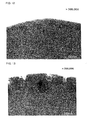
- FIB-SIM FIB-SIM observation
- the exposed section is observed from above and at an angle of 45 degrees with respect to the exposed section.
- Figures 1 and 2 show SIM images, respectively.
- Figure 1 shows the negative electrode of the battery A1 and Figure 2 shows the negative electrode of the battery B2.
- Figure 2 shows the negative electrode of the battery B2.
- a surface portion of each column of the thin film appears white due to the presence of pores.
- the upper inner portion of the thin film appears partly darkened due to the absence of pores.
- the thin film portion in the vicinity of the current collector appear mostly white. This demonstrates that the thin film has a markedly high degree of porosity at its portion adjacent to the current collector.
- the negative electrode of the rechargeable lithium battery using the nonaqueous electrolyte containing at least 0.01 weight % dissolved carbon dioxide in accordance with the present invention a portion of the thin film that appears white due to the presence of pores is very small, as can be seen from Figure 1 .
- the negative electrode is found to have a very low porosity at its portion adjacent to the current collector.
- the battery A1 was disassembled in the argon atmosphere to remove its negative electrode.
- the battery B2 was disassembled in the argon atmosphere to remove its negative electrode.
- FIG. 12 shows a TEM image of the negative electrode of the battery A1
- Figure 13 shows a TEM image of the negative electrode of the battery B1.
- an entire black region indicates a section of the thin film in the negative electrode.
- An upper end of the black region i.e., a boundary of the black and white regions indicates an ultimate surface of the thin film in the negative electrode or a contact surface with the nonaqueous electrolyte.
- a dark region is observed near the thin film surface of the negative electrode. This dark region is about 50 nm thick for the battery A1 and about 150 nm thick for the battery B1.
- the negative electrode thin film of the battery A1 in accordance with the present invention has a thinner dark region than that of the battery B1.
- FIG. 14 shows an oxygen concentration at and near the surface of the negative electrode thin film of the battery A1.
- Figure 15 shows an oxygen concentration at and near the surface of the negative electrode thin filmof the battery B1.
- the vertical line at the depth of 0 nm indicates a boundary between the dark region and the light region.
- a negative electrode region having a high oxygen concentration for the battery A1 is smaller in thickness than for the battery B1.
- the thin film of each negative electrode was at its surface portion etched by an Ar (argon) ion and its composition along the depth of the surface portion was analyzed by X-ray photoelectron spectroscopy.
- Figure 16 shows an Si concentration and an Si oxide concentration at and near the surface of the negative electrode thin film of the battery A1.
- Figure 17 shows an Si concentration and an Si oxide concentration at and near the surface of the negative electrode thin film of the battery B1.
- the Si oxide exists in a large quantity over a thinner region in the surface portion of the negative electrode of the battery A1 than in the surface portion of the negative electrode of the battery B1, demonstrating that the oxidation reaction of Si is retarded in the battery A1.
- the nonaqueous electrolyte if containing at least 0.01 weight % dissolved carbon dioxide, retards oxidation of Si that occurs during charge and discharge.
- oxidation of Si proceeds significantly. This appears to increase a porosity of the silicon thin film and expand its volume. It is believed that such oxidation of silicon and porosity increase inside the silicon thin film can be retarded by dissolving at least 0.01 weight % carbon dioxide in the nonaqueous electrolyte in accordance with the present invention.
- dissolving at least 0.01 weight % of carbon dioxide in the nonaqueous electrolyte results in retarding increase in porosity of the thin film and accordingly suppressing increase in thickness of the noncrystalline silicon thin film.
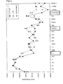
- FIG. 3 is a positive ion TOF-SIMS spectrum and Figure 4 is a negative ion TOF-SIMS spectrum.
- LiPF6 + CO2 shows a spectrum for the battery A1 of the present invention
- LiPF6 shows a spectrum for the battery B1
- LiPF6 +VC20wt% shows a spectrum for the battery B2.
- this film is a stable film having a high lithium-ion conducting capability and that the formation of such a film on the thin film surface suppresses property change of the thin film and retards porosity increase of the thin film in a charge-discharge process during which lithium is stored and released from the thin film.
- a film containing an Si active material is formed in the negative electrode for the batteries B1 and B2.
- the formation of such a film may be a probable cause of porosity increase at the surface of the active material. It is believed that the present invention prevents formation of such a film to successfully retard porosity increase of the active material.
- LiPF 6 1 mole/liter of LiPF 6 was dissolved in a mixed solvent containing ethylene carbonate and diethyl carbonate at a 3:7 ratio by volume to prepare a solution.
- Vinylene carbonate was added to this solution in the amount of 2 weight % to prepare a nonaqueous electrolyte c2.
- Carbon dioxide was blown for 30 minutes into the nonaqueous electrolyte c2 at 25 °C until carbon dioxide was dissolved therein to saturation. As a result, a nonaqueous electrolyte c1 was obtained. The amount of dissolved carbon dioxide was 0.37 weight %.
- the nonaqueous electrolytes c1 and c2 are clarified as follows:
- Rechargeable lithium batteries were fabricated using the above-prepared negative electrode, positive electrode and nonaqueous electrolytes.
- the positive and negative electrodes were rolled up in a cylindrical configuration with a porous polyethylene separator between them.
- This electrode group and each nonaqueous electrolyte were inserted in an outer casing made of an aluminum laminate.
- the outer casing was heat sealed at its peripheries such that leading ends of the positive and negative current collecting tabs extended outwardly from the outer casing, thereby completing fabrication of the battery.
- the battery fabricated using the nonaqueous electrolyte c1 was designated as C1.
- the battery fabricated using the nonaqueous electrolyte c2 was designated C2. Fabrication of the battery C1 was performed in the high-purity carbon dioxide gas atmosphere.
- the thus-fabricated rechargeable lithium batteries C1 and C2 were subjected to a charge-discharge cycle test. Each battery at 25 °C was charged at a constant current of 600 mA to 4.2 V, charged at a constant voltage of 4 . 2 V to 30 mA and then discharged at a current of 600 mA to 2.75 V. This was recorded as a unit cycle of charge and discharge.
- the 500th-cycle discharge capacity was divided by the 1st-cycle discharge capacity to give a capacity retention rate as shown in Table 6.
- Table 6 also shows a thickness increase of the battery after 500 cycles and a thickness increase of the active material per layer of the electrode as calculated from the value for the thickness increase of the battery.
- Copper was deposited by an electrolytic process on a surface of a heat-resisting, rolled copper alloy foil composed of a zirconium-copper alloy (zirconium content by weight of 0.03 %) to provide a surface-roughened, heat-resisting copper alloy foil (having an arithmetic mean roughness Ra of 0.25 ⁇ m and a thickness of 26 ⁇ m) for use as a current collector.
- An amorphous silicon thin film was deposited on the current collector under the conditions specified in Table 7. In this experiment, a direct current pulse is supplied to initiate sputtering. However, film deposition can also be effected under the similar conditions by direct current or radio-frequency sputtering.
- sccm is a unit of flow rate and is an abbreviation of standard cubic centimeter per minute.
- the obtained thin film was cut into a 25 mm x 25 mm size to use as a negative electrode a3.
- An amorphous Si-Co alloy thin film was deposited on the same current collector as used in the preparation of the negative electrode a3, using the dual source sputtering apparatus shown in Figure 8 , wherein a direct current pulse and a radio-frequency were applied to an Si target and a Co target, respectively. Particular deposition conditions are listed in Table 8.
- a chamber 1 encloses a rotational cylindrical substrate holder 2.
- the current collector was mounted on a surface of the substrate holder 2.
- the chamber 1 also encloses an Si sputter source 3 to which a DC pulse power source 4 is connected.
- the chamber 1 also encloses a Co sputter source 8 to which an RF power source 9 is connected.
- the chamber 1 is provided with a gas inlet 6 through which an Ar gas is introduced and a gas outlet 7 from which an interior of the chamber 1 is evacuated.
- a direct current pulse from the DC pulse power source 4 was applied to the Si sputter source 3, while a radio-frequency from the RF power source 9 was applied to the Co sputter source 8, to produce their respective plasmas 5, so that a noncrystalline Si-Co alloy thin film was deposited on the current collector mounted on a surface of the substrate holder 2.
- the specific deposition conditions are shown in Table 8.
- the Co concentration of the prepared alloy thin film was found to be 30 weight %, when measured by fluorescent X-ray analysis. Also, the amorphous nature of the thin film was confirmed by X-ray diffraction analysis.
- the obtained Si-Co thin film while carried on the current collector was cut into a 2.5 cm x 2.5 cm size to provide a negative electrode a4.
- amorphous Si-Fe alloy thin film was deposited on the same current collector as used in the preparation of the negative electrodes a3 and a4, using a dual source sputtering apparatus which was identical to the apparatus shown in Figure 8 , except that the Co sputter source was replaced by an Fe sputter source.
- Deposition of the amorphous Si-Fe alloy thin film was initiated by applying a DC pulse and a radio-frequency to the Si target and Fe target, respectively. Particular deposition conditions are shown in Table 9.
- the Fe concentration of the prepared alloy thin film was found to be 17 weight %, when measured by fluorescent X-ray analysis. Also, the amorphous nature of the thin film was confirmed by X-ray diffraction analysis.
- the obtained Si-Fe thin film while carried on the current collector was cut into a 2 . 5 cm x 2.5 cm size to provide a negative electrode a5.
- the prepared slurry was coated on an aluminum foil as a current collector, dried and then calendered using a calender roll.
- the resultant was cut into a 20 mm x 20 mm size to provide a positive electrode.
- the negative electrodes a3, a4 and a5 were respectively used in combination with the nonaqueous electrolyte a1 to fabricate rechargeable lithium batteries A3, A4 and A5.
- the negative electrodes a3, a4 and a5 were respectively used in combination with the nonaqueous electrolyte b1 to fabricate rechargeable lithium batteries B3, B4 and B5.
- the thus-fabricated batteries A3 - A5 and B3 - B5 were subjected to a charge-discharge cycle test under the same conditions as in Experiment 1. Their discharge capacities and capacity retention rates on the 100th cycle and 200th cycle were shown in Table 10.
- the batteries A4 and A5 using the nonaqueous electrolyte containing at least 0.01 weight % dissolved carbon dioxide show marked capacity retention improvements, compared to the batteries B4 and B5 using the nonaqueous electrolyte in which carbon dioxide was not dissolved.
- the batteries A4 and B4 were disassembled to remove their negative electrodes.
- a section of each negative electrode was observed using an SEM (scanning electron microscope) to measure a thickness of its noncrystalline silicon alloy thin film.
- the thickness measured for the noncrystalline silicon alloy thin film is shown in Table 11. In Table 11, the discharge capacity integrated over 200 cycles is also shown.
- the noncrystalline silicon-cobalt alloy thin film in the battery A4 according to the present invention exhibits a much higher integrated discharge capacity than that in the battery B4, although its thickness increase is very small.
- the thickness increase of the thin film when using the noncrystalline silicon-cobalt alloy is smaller than when using the noncrystalline silicon, demonstrating that the effect of using at least 0.01 weight % carbon dioxide is more significant.
- LiClO 4 Under carbon dioxide atmosphere, 1 mole/liter of LiClO 4 was dissolved in a mixed solvent containing ethylene carbonate (EC) and diethyl carbonate (DEC) at a 3:7 ratio by volume. The resulting electrolyte solution was bubbled with carbon dioxide to dissolve carbon dioxide therein, so that a nonaqueous electrolyte a6 was prepared.
- EC ethylene carbonate
- DEC diethyl carbonate
- LiClO 4 Under argon atmosphere, 1 mole/liter of LiClO 4 was dissolved in a mixed solvent containing ethylene carbonate (EC) and diethyl carbonate (DEC) at a 3:7 ratio by volume to prepare a nonaqueous electrolyte b6.
- EC ethylene carbonate
- DEC diethyl carbonate
- the batteries A3, A6 and A7 using the nonaqueous electrolyte containing at least 0.01 weight % dissolved carbon dioxide show marked capacity retention improvements, compared to the batteries B3, B6 and B7 using the nonaqueous electrolyte in which carbon dioxide was not dissolved. The difference is marked particularly when the nonaqueous electrolyte contains the fluorine-containing compound.
- nonaqueous electrolyte a1 (in which CO 2 was dissolved) and the nonaqueous electrolyte b1 (in which CO 2 was not dissolved), both prepared in Experiment 1, were mixed in the varied volume ratios within the range of 0:100 - 100:0, as specified in Table 13, to prepare nonaqueous electrolytes a8 - a10.
- the batteries A1 and A8 - A10 using the nonaqueous electrolyte containing at least 0.01 weight % dissolved carbon dioxide exhibit higher capacity retention rates than the comparative battery B1. It is appreciated, that the amount of a carbon dioxide gas dissolved in the nonaqueous electrolyte is at least 0.01 % by weight, preferably at least 0.1 % by weight.
- the amount of carbon dioxide dissolved in the nonaqueous electrolyte was 0.36 weight %, when measured in the same manner as in Experiment 1.
- VC vinylene carbonate
- EC ethylene carbonate
- DEC diethyl carbonate
- 3:7 ratio by volume a mixed solvent containing ethylene carbonate (EC) and diethyl carbonate (DEC) at a 3:7 ratio by volume to prepare three different solvents containing vinylene carbonate in the respective amounts of 1 %, 5 % and 10 %, based on the total weight of EC and DEC.
- 1 mole/liter of LiPF 6 was dissolved in each solvent.
- These electrolyte solutions were each bubbled with carbon dioxide so that carbon dioxide was dissolved therein to saturation.
- nonaqueous electrolytes a12 (containing 1 % by weight of VC), a13 (containing 5 % by weight of VC) and a14 (containing 10 % by weight of VC) were prepared.
- the amount of dissolved carbon dioxide was 0. 37 % by weight for all nonaqueous electrolytes a12 - a14 , when measured in the same manner as in Experiment 1.
- the thus-fabricated rechargeable lithium batteries A11 - A14 were subjected to a charge-discharge cycle test under the same conditions as in Experiment 1. Their discharge capacities and capacity retention rates on the 100th cycle and 300th cycle were shown in Table 15. In Table 15, the results for the batteries A1 and B1 are also shown.
- the charge-discharge cycle performance improving effect obtained by dissolving carbon dioxide in the nonaqueous electrolyte becomes large when the nonaqueous electrolyte uses a mixed solvent containing ethylene carbonate or propylene carbonate as a cyclic solvent and diethyl carbonate as a chain carbonate.
- the amount by weight of vinylene carbonate incorporated in the mixed solvent is preferably up to 10 %, more preferably up to 5 %, based on the total weight of the cyclic carbonate, excluding vinylene carbonate, and the chain carbonate.
- LiPF 6 LiPF 6 + ethylene carbonate (EC) and diethyl carbonate (DEC) at the volume ratio specified below.
- EC ethylene carbonate
- DEC diethyl carbonate
- LiPF 6 LiPF 6 + ethylene carbonate (EC) and dimethyl carbonate (DMC) at a 3:7 ratio by volume.
- EC ethylene carbonate
- DMC dimethyl carbonate
- the resulting solution was bubbled with carbon dioxide to dissolve carbon dioxide therein to saturation, thereby preparing a nonaqueous electrolyte a22.
- LiPF 6 LiPF 6 + ethylene carbonate
- MEC methyl ethyl carbonate
- LiPF 6 LiPF 6 + a mixed solvent containing 5 parts by weight of vinylene carbonate (VC) and 100 parts by weight of diethyl carbonate(DEC).
- VC vinylene carbonate
- DEC diethyl carbonate
- LiPF 6 LiPF 6 + LiPF 6 + VC + vinylene carbonate
- DMC dimethyl carbonate
- LiPF 6 LiPF 6 + a mixed solvent containing 5 parts by weight of vinylene carbonate (VC) and 100 parts by weight of methyl ethyl carbonate (MEC).
- VC vinylene carbonate
- MEC methyl ethyl carbonate
- the thus-fabricated rechargeable lithium batteries A15 - A26 were subjected to a charge-discharge cycle test under the conditions differed from those in Experiment 1.
- each battery was charged and discharged three time at a constant current of 9.1 mA to a voltage range of 4.2 - 2.75 V.
- the next cycle was recorded as the first cycle.
- the battery was charged at a constant current of 9.1 mA to 4.2 V.
- cut-off current of 0.45 mA After further constant-voltage charging (cut-off current of 0.45 mA), it was discharged at the constant current to 2.75 V.
- Capacity retention % 200 ⁇ th - cycle discharge capacity / 1 ⁇ st - cycle discharge capacity x 100.
- the measurement results are shown in Tables 16 - 18. In Table 16, the result for the battery A1 is also shown.
- the cycle performance characteristic increases slightly when the ethylene carbonate content is small (0.1 - 20 volume %) or relative large (50 - 70 volume %), as shown in Table 16.
- BC butylene carbonate
- DMC dimethyl carbonate
- MEC methyl ethyl carbonate
- DEC diethyl carbonate
- DMC dimethyl carbonate
- MEC methyl ethyl carbonate
- Copper was deposited by an electrolytic process on a surface of a heat-resisting, rolled copper alloy foil composed of a zirconium-copper alloy (zirconium content by weight of 0.03 %) to provide a surface-roughened, heat-resisting copper alloy foil (having an arithmetic mean roughness Ra of 0.25 ⁇ m and a thickness of 31 ⁇ m) for use as a current collector.
- a noncrystalline silicon thin film was deposited on this current collector using the electron-beam deposition apparatus shown in Figure 9 .
- the electron-beam deposition apparatus 21 includes a chamber 22, a deposition source 23, a rotary drum 24, a radiation heat shielding plate 25, a shutter 26 and a vacuum evacuation apparatus 27.
- An interior of the chamber 22 is partitioned by the radiation heat shielding plate 25 to provide a room 22a for installing the deposition source 23 and a room 22b located above the deposition source 23 for installing the rotary drum 24.
- the deposition source 23 is comprised of an electron gun 28, a crucible 29, a hearth liner 30 and a deposition material 31.
- the electron gun 28 is operable to emit an electron beam sufficient to heat and evaporate the deposition material 31.
- the crucible 29 is covered with the carbon hearth liner 30 which collects the deposition material 31.
- the rotary drum 24 is constructed such that it rotates in a predetermined direction and can be cooled by passing circulating water through an interior of the rotary drum.
- the current collector 32 is mounted on a peripheral surface of the rotary drum 24.
- the radiation heat shielding plate 25 has at its center an opening 25a which can be closed by the shutter 26.
- the shutter 26 has a stainless steel covering plate 26a which is movable to a position where the opening 25a is completely covered and thus closed.
- a noncrystalline silicon thin film was deposited on the current collector using the electron-beam deposition apparatus shown in Figure 9 .
- An interior of the chamber was vacuum evacuated to 1 x 10 -4 Pa. While the shutter was closed, the deposition material was irradiated with an electron beam for 10 minutes so that it was thermally melted and its interior gas was removed. Concurrently, the crucible, hearth liner, inner walls of the chamber, radiation heat shielding plate and shutter were exposed to a radiation heat from the deposition material, so that impurities incorporated therein by absorption and adsorption, such as oxygen and moisture, were released. Then, the electron beam irradiation was stopped to allow them to stand and release heat, while an interior of the room was continuously evacuated using the vacuum evacuation apparatus.
- the obtained thin film while carried on the current collector was cut into a 2.5 cm x 2.5 cm size.
- the subsequent attachment of a negative tab resulted in preparation of a negative electrode a27.
- the testing was discontinued after 200 cycles.
- the batteries A27 and A1 the testing was discontinued after 300 cycles.
- the batteries A27 and A1 in accordance with the present invention exhibits good charge-discharge performance characteristics.
- the battery A 27 having the thin film formed by an evaporation process shows better charge-discharge performance characteristics.
- Table 21 shows the integrated discharge capacity of each battery, which is a total discharge capacity integrated over the entire cycles in the cycle test, and the thickness change of its electrode prior to and subsequent to charge-discharge cycling, when measured by a micrometer.
- the batteries A27 and A1 in accordance with the present invention show higher integrated discharge capacities and their electrodes show smaller thickness increase.
- the battery A 27 having the thin film formed by an evaporation process exhibits a higher integrated discharge capacity and a smaller change in thickness of its electrode. Because the integrated discharge capacity is nearly proportional to the amount of lithium that is stored and released over 300 cycles, more lithium must have been stored and released in the battery A27 than in the battery A1. Nevertheless, the thickness increase of the electrode that results from the porosity increase inside the thin film has been more suppressed in the battery A27 than in the battery A1.
- the three-beaker cell shown in Figure 11 was fabricated using the negative electrode a27 and the negative electrode a1 (used in the battery A1).
- the negative electrode a27 or a1 was placed in a container 45 to serve as a working electrode 44.
- a counter electrode 46, formed from metallic lithium, and a reference electrode 47 were placed in the container 45.
- a nonaqueous electrolyte solution 48 was then introduced into the container 45 to obtain a beaker cell 43.
- a charge-discharge test was conducted using the thus-fabricated beaker cell. This cell was charged at a constant current of 4 mA until a potential of the working electrode 44 reached 0 V versus a standard potential of the reference electrode 47, and then discharged at the constant current until the working electrode 44 potential increased to 2.0 V. This charge-discharge cycle was recorded as a unit cycle. Charge-discharge cycling was discontinued after 10 cycles. A maximum discharge capacity, among those measured over 10 cycles, was divided by an electrode area to give a maximum discharge capacity per unit area, which value was further divided by a film thickness to give a maximum discharge capacity per unit volume. The maximum discharge capacity per unit area and the maximum discharge capacity per unit volume, for each of the electrodes a27 and a1, are shown in Table 22.
- the electrode a27 having the thin film formed by an electron beam evaporation process exhibits a lower discharge capacity relative to the electrode a1 having the thin film formed by a sputtering process. This follows that a smaller amount of lithium is stored and released per unit volume of the electrode. It is therefore believed that the former electrode is less susceptible to volume change when it stores and releases lithium. This probably explains the small change in thickness of the electrode prior to and subsequent to cycling, which is shown in Table 21.
- the electrode 27a exhibits better cycle performance characteristics than the electrode a1. This is most probably due to the small volumetric change that reduces the occurrence of the noncrystalline silicon to shed from the current collector and lowers a possibility of destruction of a stable protective film formed on a surface of the noncrystalline silicon. It is therefore comprehended that the maximum discharge capacity per unit volume of the active material thin film is preferably brought within 0 . 7 mAh/cm 2 ⁇ m in order to fully attain the effect of carbon dioxide dissolved in the nonaqueous electrolyte.
Landscapes
- Chemical & Material Sciences (AREA)
- Chemical Kinetics & Catalysis (AREA)
- Electrochemistry (AREA)
- General Chemical & Material Sciences (AREA)
- Engineering & Computer Science (AREA)
- Manufacturing & Machinery (AREA)
- Physics & Mathematics (AREA)
- Condensed Matter Physics & Semiconductors (AREA)
- General Physics & Mathematics (AREA)
- Inorganic Chemistry (AREA)
- Materials Engineering (AREA)
- Secondary Cells (AREA)
- Cell Electrode Carriers And Collectors (AREA)
- Battery Electrode And Active Subsutance (AREA)
Abstract
Description
- The present invention relates to a rechargeable lithium battery and also to a method for fabrication thereof.
- As one of new types of high-power and high-energy density rechargeable batteries, a rechargeable lithium battery has been recently utilized which is charged and discharged by the transfer of lithium ions through a nonaqueous electrolyte solution between the positive and negative electrodes.
- For such a rechargeable lithium battery, a negative electrode using a lithium-alloying material, such as silicon, for the negative active material has been studied. However, in the case where the lithium-alloying material, such as silicon, is used as the active material of the negative electrode, the active material is powdered or falls off from the current collector during charge and discharge because the active material expands and shrinks in volume when it stores and releases lithium. This lowers the current-collecting capacity of the electrode and accordingly deteriorates charge-discharge cycle performance characteristics, which has been a problem.
-
US 6,235,427 B1 discloses a nonaqueous secondary battery comprising a positive electrode having a positive electrode active material, a negative electrode having a negative electrode material, and a nonaqueous electrolyte, wherein the positive electrode active material is a transition metal oxide capable of intercalating and deintercalating lithium, and the negative electrode material comprises at least one silicic material capable of intercalating and deintercalating lithium selected from silicon, silicon alloy and a silicide, and a process for producing the nonaqueous secondary battery.WO 02/058182 A1
The present applicant has proposed an electrode which uses silicon as active material and improves cycle performance characteristics of rechargeable lithium batteries (Patent Document 1). More specifically, the electrode has a noncrystalline silicon thin film deposited on a current collector by a thin film-forming method such as a sputtering, chemical vapor deposition (CVD process) or evaporation method. The present applicant has also proposed an electrode, for use in rechargeable lithium batteries, fabricated by incorporating cobalt or other element into silicon (Patent Document 2). For rechargeable lithium batteries using carbon material or metallic lithium as a negative active material, dissolving of carbon dioxide in nonaqueous electrolytes has been proposed (for example, Patent Documents 3 - 13). - Patent Document 1:
PCT Int. Publication No. WO 01/29,913 - Patent Document 2:
PCT Int. Publication No. WO 02/071,512 - Patent Document 3:
U.S. Patent No. 4,853,304 - Patent Document 4: Japanese Patent Laid-Open No.
Hei 6-150975 - Patent Document 5: Japanese Patent Laid-Open No.
Hei 6-124700 - Patent Document 6: Japanese Patent Laid-Open No.
Hei 7-176323 - Patent Document 7: Japanese Patent Laid-Open No.
Hei 7-249431 - Patent Document 8: Japanese Patent Laid-Open No.
Hei 8-64246 - Patent Document 9: Japanese Patent Laid-Open No.
Hei 9-63649 - Patent Document 10: Japanese Patent Laid-Open No.
Hei 10-40958 - Patent Document 11: Japanese Patent Laid-Open No.
2001-307771 - Patent Document 12: Japanese Patent Laid-Open No.
2002-329502 - Patent Document 13: Japanese Patent Laid-Open No.
2003-86243 - The rechargeable lithium battery using the thin film of noncrystalline silicon for the negative active material, as proposed by the present applicant, exhibits a high charge-discharge capacity and good cycle performance characteristics. However, the active material layer increases in porosity with repetitive charge-discharge cycling to result in increasing a thickness of the active material layer, which has been a problem.
- It is an object of the present invention to provide a rechargeable lithium battery using a negative electrode made by depositing a noncrystalline thin film containing at least 50 atomic % of silicon on a current collector, which exhibits a high charge-discharge capacity and improved cycle characteristics and which can suppress increase in porosity and thickness of the active material after charges and discharges, as well as providing a method for fabrication thereof.
- The rechargeable lithium battery of the present invention includes a negative electrode made by depositing a noncrystalline thin film containing at least 50 atomic % of silicon on a current collector, a positive electrode and a nonaqueous electrolyte wherein the nonaqueous electrolyte contains carbon dioxide dissolved therein, characterized in that the amount of carbon dioxide dissolved in said nonaqueous electrolyte is at least 0.01 weight %.
- In the present invention, the nonaqueous electrolyte contains carbon dioxide dissolved therein. This means that the nonaqueous electrolyte contains carbon dioxide purposely or intentionally dissolved therein. Although carbon dioxide inevitably dissolves in a nonaqueous electrolyte during a general fabrication process of rechargeable lithium batteries, such dissolved carbon dioxide is not meant to be included within the scope. Carbon dioxide generally dissolves into a solvent of a nonaqueous electrolyte. Accordingly, the nonaqueous electrolyte may be prepared by dissolving a solute and then carbon dioxide into a solvent. Alternatively, the nonaqueous electrolyte may be prepared by dissolving carbon dioxide and then a solute into a solvent.
- A porosity increase of the active material layer, which occurs with a charge-discharge reaction, can be retarded by dissolving carbon dioxide in a nonaqueous electrolyte. A thickness increase of the active material layer during charge and discharge can be accordingly suppressed to result in the increased volumetric energy density of the rechargeable lithium battery.
- As disclosed in Patent Document 1, the electrode using a noncrystalline thin film containing at least 50 atomic % of silicon as the active material is known to exhibit improved charge-discharge performance characteristics if the thin film is divided into columns by gaps formed therein in a manner to extend in a thickness direction of the thin film. The spaces defined to surround the columnar portions serve to accommodate a change in volume of the thin film that occurs when it expands and shrinks on charge and discharge and thereby suppress production of a stress, so that separation of the thin film from the current collector can be prevented. The gaps extending in the thickness direction of the thin film are formed to originate from valleys of the irregularities on a surface of the thin film.
- The inventors of this application have found that, when such an electrode is repeatedly charged and discharged, the thin film having the laminar structure shows a gradual increase of porosity that advances inside from its surface. As the porosity increases, the thickness of the thin film increases. As a result, the volumetric energy density of the thin film decreases. This porosity increase of the thin film is believed due to the property change of the silicon active material that occurs as it undergoes an irreversible reaction.
- Dissolving of carbon dioxide in a nonaqueous electrolyte, in accordance with the present invention, suppresses a porosity increase of the thin film. This accordingly suppresses a thickness increase and thereby increases a volumetric energy density of the thin film. The detailed reason why dissolving of carbon dioxide in a nonaqueous electrolyte results in retarding a porosity increase of the thin film is not clear, but is most probably due to the formation of a stable film having a high lithium-ion conducting capability on a surface of the thin film.
- In the present invention, the amount of carbon dioxide dissolved in a nonaqueous electrolyte is at least 0.01 % by weight, preferably at least 0.1 % by weight. It is generally preferred that carbon dioxide is dissolved in a nonaqueous electrolyte to saturation. The above-specified amount of dissolved carbon dioxide does not include the amount of carbon dioxide which inevitably dissolves in a nonaqueous electrolyte, i.e. , excludes the amount of carbon dioxide which dissolves in a nonaqueous electrolyte during a general fabrication process of rechargeable lithium batteries. The above-specified amount of dissolved carbon dioxide can be determined by measuring a weight of a nonaqueous electrolyte both subsequent to and prior to dissolving of carbon dioxide therein. Specifically, it can be calculated using the following equation:
-

In the present invention, the negative electrode made by depositing a noncrystalline thin film containing at least 50 atomic % of silicon on a current collector is used. The term noncrystalline, as used herein, is meant to encompass an amorphous film and a microcrystalline film having a crystallite size of up to 100 nm. Judgement of whether the thin film is amorphous and measurement of a crystallite size of the microcrystalline thin film can be made by observing the presence of a peak in an X-ray diffraction spectrum and applying a half band width of the peak to a Scherrer equation. As can be appreciated from the above definition, the noncrystalline thin film in the present invention does not include single crystal and polycrystalline thin films. - . Examples of such alloys include those containing silicon and at least one selected from cobalt, iron, zinc and zirconium. Specific examples include Si-Co, Si-Fe, Si-Zn and Si-Zr alloy thin films.
- In the present invention, the current collector surface on which the thin film is deposited preferably has an arithmetic mean roughness Ra of at least 0.1 µm. The arithmetic mean roughness Ra is defined in Japanese Industrial Standards (JIS B 0601-1994) and can be measured as by a feeler-type surface roughness meter. Deposition of the thin film on the current collector having such large irregularities results in the formation of the corresponding irregularities on a surface of the deposited thin film. In the case where the noncrystalline thin film having such large irregularities is used as active material, when a battery is charged and discharged, a stress engendered due to expansion and shrinkage of the thin film concentrates at valleys of the irregularities of the thin film, so that gaps are formed in the thickness direction of the thin film to divide the thin film into columns, as described above. As a result, the stress produced on charge and discharge is dispersed to facilitate a reversible structural change of the noncrystalline thin film.
- On the other hand, the thin film when divided into columns significantly increases its contact area with the nonaqueous electrolyte. As described above, a property change of the active material of the prior electrode has been found to start at a thin film surface in direct contact with the nonaqueous electrolyte and result in increasing a porosity of the thin film. The present invention can suppress such a porosity increase, improve charge-discharge cycle performance characteristics, suppress a thickness increase of the thin film and improve a volumetric energy density of a battery.
- An upper limit of the arithmetic mean roughness Ra of the current collector surface is not particularly specified. However, its substantial value is preferably 10 µm or below because the thickness of the current collector is preferably in the range of 10 - 100 µm.
- In the present invention, a heat-resisting copper alloy foil is preferably used for the current collector. The heat-resisting copper alloy, as used herein, refers to a copper alloy which exhibits a tensile strength of at least 300 MPa after one hour of annealing at 200 °C. Examples of useful heat-resisting copper alloys are listed in Table 1.
-
[Table 1] (% on a Weight Basis) Type Composition Tin-Containing Copper 0.05-0.2 % Sn and 0.04 % or Less P Added to Cu Silver-Containing Copper 0.08-0.25 % Ag Added to Cu Zirconium-Copper (Used in Examples) 02-0.2 % Zr Added to Cu Chromium-Copper 0.4 - 1.2 % Cr Added to Cu Titanium-Copper 1.0 - 4.0 % Ti Added to Cu Beryllium-Copper 0.4 - 2.2 % Be, Slight Amounts of Co, Ni and Fe Added to Cu Iron-Containing Copper 0.1-2.6 % Fe and 0.01-0.3 % P Added to Cu High-Strength Brass High-Strength Brass 2.0 % or Less Al, 3.0 % or Less Mn and 1.5 % or Less Fe Added to Brass of 55.0 - 60.5 % Cu Tin-Containing Brass 80.0 - 95.0 % Cu, 1.5 - 3.5 % Sn and a Balance of Zn Phosphor Bronze Mainly of Cu and Containing 3.5 - 9.0 % Sn and 0.03 - 0.35 % P Aluminum Bronze Containing 77.0 - 92.5 % Cu, 6.0 - 12.0 % Al, 1.5 - 6.0 % Fe, 7.0 % or Less Ni and 2.0 % or Less Mn White Copper Mainly of Cu and Containing 9.0 - 33.0 % Ni, 0.40 - 2.3 % Fe, 0.20 - 2.5 % Mn and 1.0 % or Less Zn Corson Alloy 3 % Ni, 0.65 % Si and 0.15 % Mg in Cu Cr-Zr-Cu Alloy 0.2 % Cr, 0.1 % Zr and 0.2 % Zn in Cu - In the preparation of a negative electrode, a temperature change that occurs when the thin film is deposited on a current collector may reduce a mechanical strength of the current collector to the extent that makes succeeding processing difficult in the battery fabrication. The use of the heat-resisting copper alloy foil as the current collector prevents reduction in mechanical strength of the current collector that may be caused by the aforementioned temperature change and thereby insures sufficient conductivity of the current collector.
- As described above, the current collector for use in the present invention preferably has large irregularities on its surface. Unless the arithmetic mean surface roughness Ra of the heat-resisting copper alloy foil is sufficiently large, an electrolytic copper or copper alloy may be superimposed on a surface of the foil to provide large irregularities on the surface. Such electrolytic copper and copper alloy layers can be formed through an electrolytic process.
- The method of the present invention enables fabrication of the above-described rechargeable lithium battery of the present invention and is specifically for fabricating a rechargeable lithium battery including a negative electrode, a positive electrode and a nonaqueous electrolyte. The method is characterized as including the steps of depositing a noncrystalline thin film containing at least 50 atomic % of silicon on a current collector to prepare a negative electrode, dissolving at least 0.01 weight % carbon dioxide in a nonaqueous electrolyte, and assembling a rechargeable lithium battery using the negative electrode, positive electrode and nonaqueous electrolyte.
- Various methods can be utilized to dissolve at least 0.01 weight % carbon dioxide in the nonaqueous electrolyte. For example, carbon dioxide is forced to contact with the nonaqueous electrolyte. Specifically, a carbon dioxide gas is blown into the nonaqueous electrolyte. This is an efficient and easy method resulting in obtaining the nonaqueous electrolyte containing at least 0.01 weight % dissolved carbon dioxide. Other useful methods include stirring the nonaqueous electrolyte under a carbon dioxide atmosphere, and contacting a high-pressure stream of carbon dioxide with the nonaqueous electrolyte. Alternatively, a carbon dioxide generator may be added to dissolve at least 0.01 weight % carbon dioxide in the nonaqueous electrolyte. Examples of carbon dioxide generators include polycarbonates and carbonates. Dry ice may also be used.
- In the fabrication of a rechargeable lithium battery using the nonaqueous electrolyte containing at least 0.01 weight % dissolved carbon dioxide, it is preferred that the amount of carbon dioxide dissolved in the nonaqueous electrolyte is stably controlled. To this object, a rechargeable lithium battery is preferably assembled under the atmosphere including carbon dioxide. For example, a step of introducing the nonaqueous electrolyte containing dissolved carbon dioxide into the battery and the subsequent steps are preferably performed under the atmosphere including carbon dioxide. It is also preferred that, after being introduced into the battery, the nonaqueous electrolyte containing at least 0.01 weight % dissolved carbon dioxide is exposed to a high-pressure carbon dioxide atmosphere to stabilize the amount of dissolved carbon dioxide. The amount of carbon dioxide that can be dissolved to saturation varies with a temperature of the nonaqueous electrolyte. It is accordingly preferred that, in the fabrication steps, a control is provided to minimize a temperature variation of the rechargeable lithium battery.
- In the fabrication method of the present invention, the negative electrode is prepared by depositing the noncrystalline thin film containing at least 50 atomic % of silicon on the current collector. Preferably, a raw material is supplied from a vapor phase in the deposition of the noncrystalline thin film. This method allows nearly uniform deposition of the noncrystalline thin film on an irregular surface of the current collector and thus results in the formation of irregularities, on a surface of the noncrystalline thin film, which generally conform in shape to those on a surface of the underlying current collector. The raw material from a vapor phase can be deposited on the noncrystalline thin film, for example, by a sputtering, chemical vapor deposition or evaporation process. Particularly from a practical point of view, the use of the evaporation process is preferred for deposition of the noncrystalline thin film. The evaporation process, because of its high film-forming rate, is more suitable for electrode fabrication compared to the other processes.
- In the rechargeable lithium battery of the present invention, preferably, the discharge capacity per unit volume of the negative electrode does not exceed 0.7 (mAh/cm2 µm). The electrode having such a discharge capacity can be prepared by depositing the noncrystalline thin film using a evaporation process. The discharge capacity per unit volume can be calculated by dividing a discharge capacity per unit area by a thickness of the noncrystalline thin film. The discharge capacity per unit volume is nearly equivalent to the amount of lithium that is stored and released from the active material. It is therefore believed that the lower the discharge capacity per unit volume, the smaller the volumetric change produced per unit volume of the active material to result in obtaining better cycle performance characteristics.
- A solvent of the nonaqueous electrolyte for use in the rechargeable lithium battery of the present invention is not particularly specified in type but can be illustrated by a mixed solvent of cyclic carbonate and chain carbonate. Examples of cyclic carbonates include ethylene carbonate, propylene carbonate, butylene carbonate and vinylene carbonate. Examples of chain carbonates include dimethyl carbonate, methyl ethyl carbonate and diethyl carbonate. Also applicable is a mixed solvent which contains any of the above-listed cyclic carbonates and an ether solvent such as 1,2-dimethoxyethane or 1,2-diethoxyethane. In the case where a cyclic carbonate having an unsaturated carbon bond, such as vinylene carbonate, is contained as a solvent, such a cyclic carbonate is preferably contained in the amount by weight of 0.1 - 10 %, based on the total weight of the cyclic carbonate (excluding the cyclic carbonate having an unsaturated carbon bond) and the chain carbonate. Another example of the cyclic carbonate having an unsaturated carbon bond is vinylethylene carbonate.
- A solute of the nonaqueous electrolyte can be illustrated by LiPF6, LiBF4, LiCF3SO3, LiN(CF3SO2)2, LiN(C2F5SO2)2, LiN(CF3SO2) (C4F9SO2), LiC(CF3SO2)3, LiC(C2F5SO2)3, LiAsF6, LiClO4, Li2B10Cl10, Li2B12Cl12 and mixtures thereof. Preferred for use as the solute are LiXFy (wherein X is P, As, Sb, B, Bi, Al, Ga or In; y is 6 if X is P, As or Sb and y is 4 if X is B, Bi, Al, Ga or In); lithium perfluoroalkylsulfonyl imide LiN(CmF2m+1SO2) (CnF2n+1SO2) (wherein m and n are independently integers of 1 - 4) ; and lithium perfluoroalkylsulfonyl methide LiN (CpF2p+1SO2) (CqF2q+1SO2) (CrF2r+1SO2) (wherein p, q and rare independently integers of 1 - 4). Among them, the use of LiPF6 is particularly preferred. Other applicable electrolytes include, for example, gelled polymer electrolytes comprised of an electrolyte solution impregnated into polymer electrolytes such as polyethylene oxide and polyacrylonitrile. The electrolyte for the rechargeable lithium battery of the present invention can be used without limitation, so long as a lithium compound as its solute that imparts ionic conductivity, as well as its solvent that dissolves and retains the lithium compound, remain undecomposed at voltages during charge, discharge and storage of the battery.
- Also in the present invention, the nonaqueous electrolyte preferably contains a fluorine-containing compound or LiClO4. Examples of such fluorine-containing compounds include LiXFy (wherein X is P, As, Sb, B, Bi, Al, Ga or In; y is 6 if X is P, As or Sb and y is 4 if X is B, Bi, Al, Ga or In) and LiN (CpF2p+1SO2) (CqF2q+1SO2) (CrF2r+SO2) (wherein p, q and r are independently integers of 1 - 4), which are both useful as the aforementioned solute, and a fluorine-containing lithium borate. The fluorine-containing lithium borate can be illustrated by LiBF2(Ox).
- Examples of useful positive electrode materials for the rechargeable lithium battery of the present invention include lithium-containing transition metal oxides such as LiCoO2, LiNiO2, LiMn2O4. LiMnO2, LiCo0.5Ni0.5O2 and LiNi0.7Co0.2Mn0.1O2 ; and lithium-free metal oxides such as MnO2. Other substances can also be used, without limitation, if they are capable of electrochemical lithium insertion and deinsertion.
- In accordance with the present invention, a rechargeable lithium battery can be provided which has a high charge-discharge capacity and in which a porosity increase of the active material layer during charge and discharge can be suppressed and accordingly a thickness increase of the active material layer after charge and discharge can be suppressed.
-
- [
Fig. 1] Figure 1 is an FIB-SIM image showing a section of the negative electrode of the rechargeable lithium battery A1 in accordance with the present invention; - [
Fig. 2] Figure 2 is an FIB-SIM image showing a section of the negative electrode of the comparative battery B2; - [
Fig. 3] Figure 3 is a spectrum showing the TOF- SIMS surface analysis results (positive ions) for the negative electrode; - [
Fig.4] Figure 4 is a spectrum showing the TOF-SIMS surface analysis results (negative ions) for the negative electrode; - [
Fig. 5] Figure 5 is a schematic view, showing the sputtering apparatus employed in the Example in accordance with the present invention; - [
Fig. 6] Figure 6 is a perspective view, showing the rechargeable lithium battery fabricated in the Example in accordance with the present invention; - [
Fig. 7] Figure 7 is a schematic sectional view, showing the rechargeable lithium battery fabricated in the Example in accordance with the present invention; - [
Fig. 8] Figure 8 is a schematic view, showing the dual source sputtering apparatus employed in the Example in accordance with the present invention; - [
Fig. 9] Figure 9 is a schematic view, showing the electron-beam deposition apparatus employed in the Example in accordance with the present invention; - [
Fig. 10] Figure 10 is a graph, showing the relationship between charge capacity and cycles of the rechargeable lithium battery in the Example in accordance with the present invention; - [
Fig. 11] Figure 11 is a schematic view, showing the three-electrode beaker cell constructed in the Example in accordance with the present invention ; - [
Fig. 12] Figure 12 is a TEM image showing the vicinity of a thin film surface of the negative electrode of the rechargeable lithium battery A1 in accordance with the present invention; - [
Fig. 13] Figure 13 is a TEM image showing the vicinity of a surface of the negative electrode thin film of the comparative battery B1; - [
Fig. 14] Figure 14 is a graph showing an oxygen concentration at and near a thin film surface of the negative electrode of the rechargeable lithium battery A1 in accordance with the present invention; - [
Fig. 15] Figure 15 is a graph showing an oxygen concentration at and near a thin film surface of the negative electrode of the comparative battery B1; - [
Fig. 16] Figure 16 is a graph showing an Si concentration and an Si oxide concentration at and near a thin film surface of the negative electrode of the rechargeable lithium battery A1 in accordance with the present invention; and - [
Fig. 17] Figure 17 is a graph showing an Si concentration and an Si oxide concentration at and near a thin film surface of the negative electrode of the comparative battery B1. -
- 1
- chamber
- 2
- substrate holder
- 3
- Si sputter source
- 4
- DC pulse power source
- 5
- plasma
- 6
- gas inlet
- 7
- gas outlet
- 8
- Co sputter source
- 9
- RF power source
- 10
- outer casing
- 11
- negative current collector
- 12
- silicon thin film
- 13
- positive current collector
- 14
- positive active material layer
- 15
- separator
- 16
- nonaqueous electrolyte
- 17
- negative tab
- 18
- positive tab
- 21
- electron-beam deposition apparatus
- 22
- chamber
- 23
- deposition source
- 24
- rotary drum
- 25
- radiation heat shielding plate
- 26
- shutter
- 27
- vacuum evacuation apparatus
- 32
- current collector
- 43
- beaker cell
- 44
- work electrode
- 45
- container
- 46
- counter electrode
- 47
- reference electrode
- 48
- nonaqueous electrolyte solution
- The present invention is below described in more detail by way of Examples. The following examples merely illustrate the practice of the present invention but are not intended to be limiting thereof. Suitable changes and modifications can be effected without departing from the scope of the present invention.
- Copper was deposited by an electrolytic process on a surface of a heat-resisting, rolled copper alloy foil composed of a zirconium-copper alloy (zirconium content by weight of 0.015 - 0.03 %) to provide a surface-roughened, heat-resisting copper alloy foil (having an arithmetic mean roughness Ra of 0.25 µm and a thickness of 31 µm) for use as a current collector. A noncrystalline silicon thin film was deposited on the current collector using the sputtering apparatus shown in
Figure 5 . - As shown in
Figure 5 , a chamber 1 encloses a rotationalcylindrical substrate holder 2. The current collector was mounted on a surface of thesubstrate holder 2. The chamber 1 also encloses anSi sputter source 3 to which a DCpulse power source 4 is connected. The chamber 1 is provided with agas inlet 6 for introducing an Ar gas and agas outlet 7 for evacuating an interior of the chamber 1. - The interior of the chamber was vacuum evacuated through the
gas outlet 7 to 1x10⁻⁴ Pa. An Ar gas was then introduced through thegas inlet 6 into the interior of the chamber 1. After a gas pressure was stabilized, a direct current pulse from the DCpulse power source 4 was applied to theSi sputter source 3 to produce aplasma 5, so that a noncrystalline silicon film was deposited on the current collector mounted on a surface of thesubstrate holder 2. The specific conditions for deposition of the thin film are listed in Table 2. -
[Table 2] DC Pulse Frequency 100 kHz DC Pulse Width 1856 ns DC Pulse Power 2000 W Argon Flow Rate 60 sccm Gas Pressure 2-2.5×10⁻¹ Pa Deposition Time 146 min. Film Thickness 5 µm - After the thin film was deposited to a thickness of 5 µm, the current collector was removed from the
substrate holder 2. The current collector while carrying the thin film thereon was cut into a 2.5 cm x 2.5 cm size. A negative tab was attached thereto to prepare a negative electrode. - 90 parts by weight of LiCoO2 powder and 5 parts by weight of artificial graphite powder as a conductor were mixed in a 5 wt. % N-methylpyrrolidone aqueous solution containing 5 parts by weight of polytetrafluoroethylene as a binder to provide a cathode mix slurry. This slurry was coated by a doctor blade process onto a 2 cm x 2 cm surface region of an aluminum foil (18 µm thick) as a positive current collector and then dried to form a layer of positive active material. A positive tab was attached onto an aluminum foil region left uncoated with the positive active material layer to prepare a positive electrode.
- 1 mole/liter of LiPF6 was dissolved in a mixed solvent containing ethylene carbonate and diethyl carbonate at a 3:7 ratio by volume to prepare a nonaqueous electrolyte b1.
- 20 weight % of vinylene carbonate was added to this nonaqueous electrolyte b1 to prepare a nonaqueous electrolyte b2.
- Carbon dioxide was blown for 30 minutes into the nonaqueous electrolyte b1 at 25 °C until carbon dioxide was dissolved therein to saturation. This resulted in obtaining a nonaqueous electrolyte a1. A weight of the nonaqueous electrolyte both after and before dissolving of carbon dioxide was measured and, as a result, the amount of dissolved carbon dioxide was determined to be 0.37 weight %.
- The nonaqueous electrolytes a1, b1 and b2 are clarified as follows:
- nonaqueous electrolyte a1: a nonaqueous electrolyte in which CO2 was dissolved
- nonaqueous electrolyte b1: a nonaqueous electrolyte in which CO2 was not dissolved
- nonaqueous electrolyte b2: a nonaqueous electrolyte to which 20 % by weight of vinylene carbonate (VC) was added.
- A rechargeable lithium battery was fabricated using the above-prepared negative electrode, positive electrode and nonaqueous electrolyte.
Figures 6 and 7 are a perspective view and a schematic sectional view, respectively, showing the fabricated rechargeable lithium battery. As shown inFigure 7 , the positive and negative electrodes are inserted in anouter casing 10 made of an aluminum laminated film. The siliconthin film 12 as the negative active material is provided on a negativecurrent collector 11. The positiveactive material layer 14 is provided on a positivecurrent collector 13. The siliconthin film 12 and the positiveactive material layer 14 are located to face toward the opposite sides of aseparator 15. Thenonaqueous electrolyte 16 is introduced in theouter casing 10. Theouter casing 10 is welded at its ends to define a sealed portion 10a. Anegative tab 17 is attached to the negativecurrent collector 11 such that its leading end extends through the sealed portion 10a to an outside. Although not shown inFigure 7 , apositive tab 18 is attached to the positivecurrent collector 13 such that its leading end also extends through the sealed portion 10a to an outside. - The battery fabricated using the nonaqueous electrolyte a1 was designated as A1. The battery fabricated using the nonaqueous electrolyte b1 was designated as B1. The battery fabricated using the nonaqueous electrolyte b2 was designated as B2. Fabrication of the rechargeable lithium battery A1 was performed in the high-purity carbon dioxide gas atmosphere.
- The thus-fabricated rechargeable lithium batteries A1, B1 and B2 were subjected to a charge-discharge cycle test. Each battery at 25 °C was charged at a current of 13 mA to 4.2 V and then discharged at a current of 13 mA to 2.75 V. This was recorded as a unit cycle of charge and discharge. The maximum discharge capacity and the 100th-cycle and 200th-cycle discharge capacities and capacity retention rates, for each battery, are listed in Table 3. The maximum discharge capacity is the highest discharge capacity among those measured for all cycles. The capacity retention rate is calculated by taking the maximum discharge capacity as being 100 %.
-
[Table 3] Battery Maximum Discharge Capacity (mAh) on 100-th Cycle on 200-th Cycle Discharge Capacity (mAh) Capacity Retention (%) Discharge Capacity (mAh) Capacity Retention (%) A1 11.17 9.89 88.5 8.66 77.5 B1 12.17 2.14 17.6 0.58 4.8 B2 11.42 8.41 73.6 5.33 46.7 - As can be clearly seen from Table 3, the battery A1 containing at least 0.01 weight % dissolved carbon dioxide in the nonaqueous electrolyte, in accordance with the present invention, shows a significant capacity retention improvement, compared to the battery B1 including the nonaqueous electrolyte in which carbon dioxide was not dissolved. Also, the battery A1 according to the present invention exhibits significantly improved capacity retention rate, compared to the battery B2 containing vinylene carbonate.
- After 200 charge-discharge cycles, each battery was disassembled and its negative electrode was removed. A section of the negative electrode was observed using an SEM (scanning electronmicroscope) to measure a thickness of the noncrystalline silicon thin film. The thickness measured for the noncrystalline silicon thin film is shown in Table 4. In Table 4, the discharge capacity integrated over 200 cycles is also shown. The integrated discharge capacity is nearly proportional to the reacting weight of lithium that is stored and released from the noncrystalline silicon thin film. It is therefore believed that the integrated discharge capacity is closely related to a progress of a porosity increasing reaction that increases a thickness of the noncrystalline silicon thin film.
-
[Table 4] Battery Integrated Discharge Capacity (mAh) Thickness of Noncrystalline Silicon Thin Film (µm) A1 1949 25 B1 851 22 B2 1657 42 - As can be clearly seen from the results shown in Table 4, the noncrystalline silicon thin film in the battery A1 according to the present invention exhibits a much higher integrated discharge capacity than that in the battery B1, although a difference in thickness therebetween is very small. The battery B2 using the nonaqueous electrolyte containing vinylene carbonate exhibits a higher integrated discharge capacity than the battery B1 but shows a large thickness increase of the amorphous silicon thin film. It is reported that, for rechargeable lithium batteries using a carbon-based negative electrode, addition of vinylene carbonate to a nonaqueous electrolyte improves cycle characteristics as a result of formation of a film on a surface of the negative electrode. However, the addition of vinylene carbonate does not lead to virtually suppressing a thickness increase of the silicon thin film, as apparent from the comparative examples. On the other hand, the increase in thickness of the noncrystalline thin film is apparently suppressed in the rechargeable lithium battery using the nonaqueous electrolyte containing at least 0.01 weight % dissolved carbon dioxide in accordance with the present invention.
- After 200 charge-discharge cycles under the same cycling conditions as specified above, the battery A1 was disassembled to remove its negative electrode. After 100 charge-discharge cycles under the same cycling conditions as specified above, the battery B2 was disassembled to remove its negative electrode. A section of each negative electrode was observed with an FIB-SIM. By the FIB-SIM observation, it is meant that the negative electrode is processed with a focused ion beam (FIB) so that its section is exposed to an outside, and then the exposed section is observed with a scanning ion microscope (SIM).
- In the SIM observation, the exposed section is observed from above and at an angle of 45 degrees with respect to the exposed section.
-
Figures 1 and 2 show SIM images, respectively. -
Figure 1 shows the negative electrode of the battery A1 andFigure 2 shows the negative electrode of the battery B2. As can be clearly seen fromFigure 2 , in the negative electrode which showed a thickness increase as related to the addition of vinylene carbonate, a surface portion of each column of the thin film appears white due to the presence of pores. The upper inner portion of the thin film appears partly darkened due to the absence of pores. However, the thin film portion in the vicinity of the current collector appear mostly white. This demonstrates that the thin film has a markedly high degree of porosity at its portion adjacent to the current collector. - On the other hand, in the negative electrode of the rechargeable lithium battery using the nonaqueous electrolyte containing at least 0.01 weight % dissolved carbon dioxide in accordance with the present invention, a portion of the thin film that appears white due to the presence of pores is very small, as can be seen from
Figure 1 . Particularly, the negative electrode is found to have a very low porosity at its portion adjacent to the current collector. - After 50 charge-discharge cycles under the same charge and discharge conditions as specified above, the battery A1 was disassembled in the argon atmosphere to remove its negative electrode. After 30 charge-discharge cycles under the same charge and discharge conditions as specified above, the battery B2 was disassembled in the argon atmosphere to remove its negative electrode.
- Each of the removed negative electrodes was processed into the form of a thin section, and a distal end of the columnar structure of the negative electrode thin film was observed with a transmission electron microscope (TEM).
Figure 12 shows a TEM image of the negative electrode of the battery A1 andFigure 13 shows a TEM image of the negative electrode of the battery B1. InFigures 12 and 13 , an entire black region, including dark and light regions, indicates a section of the thin film in the negative electrode. An upper end of the black region, i.e., a boundary of the black and white regions indicates an ultimate surface of the thin film in the negative electrode or a contact surface with the nonaqueous electrolyte. As apparent fromFigures 12 and 13 , a dark region is observed near the thin film surface of the negative electrode. This dark region is about 50 nm thick for the battery A1 and about 150 nm thick for the battery B1. Thus, the negative electrode thin film of the battery A1 in accordance with the present invention has a thinner dark region than that of the battery B1. - For the batteries A1 and B1, the thin film surface of each negative electrode was analyzed by energy dispersive X-ray spectroscopy (EDX).
Figure 14 shows an oxygen concentration at and near the surface of the negative electrode thin film of the battery A1.Figure 15 shows an oxygen concentration at and near the surface of the negative electrode thin filmof the battery B1. InFigures 14 and 15 , the vertical line at the depth of 0 nm indicates a boundary between the dark region and the light region. As can be clearly seen fromFigures 14 and 15 , a negative electrode region having a high oxygen concentration for the battery A1 is smaller in thickness than for the battery B1. - For the batteries A1 and B1, the thin film of each negative electrode was at its surface portion etched by an Ar (argon) ion and its composition along the depth of the surface portion was analyzed by X-ray photoelectron spectroscopy.
Figure 16 shows an Si concentration and an Si oxide concentration at and near the surface of the negative electrode thin film of the battery A1.Figure 17 shows an Si concentration and an Si oxide concentration at and near the surface of the negative electrode thin film of the battery B1. As can be clearly seen fromFigures 16 and 17 , the Si oxide exists in a large quantity over a thinner region in the surface portion of the negative electrode of the battery A1 than in the surface portion of the negative electrode of the battery B1, demonstrating that the oxidation reaction of Si is retarded in the battery A1. - As can be appreciated from the preceding results, the nonaqueous electrolyte, if containing at least 0.01 weight % dissolved carbon dioxide, retards oxidation of Si that occurs during charge and discharge. In the battery B1, oxidation of Si proceeds significantly. This appears to increase a porosity of the silicon thin film and expand its volume. It is believed that such oxidation of silicon and porosity increase inside the silicon thin film can be retarded by dissolving at least 0.01 weight % carbon dioxide in the nonaqueous electrolyte in accordance with the present invention.
- As can be appreciated from the above, dissolving at least 0.01 weight % of carbon dioxide in the nonaqueous electrolyte, in accordance with the present invention, results in retarding increase in porosity of the thin film and accordingly suppressing increase in thickness of the noncrystalline silicon thin film.
- For the initially-charged batteries A1, B1 and B2, a surface of each negative electrode was analyzed by TOF-SIMS (time of flight-secondary ion mass spectrometry).
Figure 3 is a positive ion TOF-SIMS spectrum andFigure 4 is a negative ion TOF-SIMS spectrum. InFigures 3 and4 , "LiPF6 + CO2" shows a spectrum for the battery A1 of the present invention, "LiPF6" shows a spectrum for the battery B1 and "LiPF6 +VC20wt%" shows a spectrum for the battery B2. - As can be clearly seen from
Figures 3 and4 , the markedly reduced Si ion and Si-containing ions and the increased Li2F+ ion at the surface of the negative electrode, relative to the batteries B1 and B2, are detected for the battery A1 in accordance with the present invention. This demonstrates that the use of the nonaqueous electrolyte containing at least 0.01 weight % dissolved carbon dioxide, in accordance with the present invention, results in the marked reduction in concentration of Si at the thin film surface. This is most probably due to the formation of an Si-free film on the surface of the thin film composed of active material. It is believed that this film is a stable film having a high lithium-ion conducting capability and that the formation of such a film on the thin film surface suppresses property change of the thin film and retards porosity increase of the thin film in a charge-discharge process during which lithium is stored and released from the thin film. - On the other hand, it is very likely that a film containing an Si active material is formed in the negative electrode for the batteries B1 and B2. The formation of such a film may be a probable cause of porosity increase at the surface of the active material. It is believed that the present invention prevents formation of such a film to successfully retard porosity increase of the active material.
- Artificial graphite as a negative active material and a styrene-butadiene rubber as a binder were mixed in an aqueous solution of carboxymethylcellulose as a thickener so that the mixture contained the active material, binder and thickener in the ratio by weight of 95:3:2. The mixture was then kneaded to prepare a negative electrode slurry. The prepared slurry was applied onto a copper foil as a current collector, dried and rolled by a pressure roll. Subsequent attachment of a current collecting tab resulted in the preparation of a negative electrode.
- 90 parts by weight of LiCoO2 powder and 5 parts by weight of artificial graphite powder as an electric conductor were mixed in a 5 wt.% N-methylpyrrolidone aqueous solution containing 5 parts by weight of polytetrafluoroethylene as a binder to provide a cathode mix slurry. This slurry was coated by a doctor blade process on an aluminum foil as a positive current collector and then dried to form a layer of positive active material. A positive tab was attached onto an aluminum foil region left uncoated with the positive active material layer to prepare a positive electrode.
- 1 mole/liter of LiPF6 was dissolved in a mixed solvent containing ethylene carbonate and diethyl carbonate at a 3:7 ratio by volume to prepare a solution.
- Vinylene carbonate was added to this solution in the amount of 2 weight % to prepare a nonaqueous electrolyte c2.
- Carbon dioxide was blown for 30 minutes into the nonaqueous electrolyte c2 at 25 °C until carbon dioxide was dissolved therein to saturation. As a result, a nonaqueous electrolyte c1 was obtained. The amount of dissolved carbon dioxide was 0.37 weight %.
- The nonaqueous electrolytes c1 and c2 are clarified as follows:
- nonaqueous electrolyte c1: a nonaqueous electrolyte in which CO2 was dissolved
- nonaqueous electrolyte c2: a nonaqueous electrolyte in which CO2 was not dissolved.
- Rechargeable lithium batteries were fabricated using the above-prepared negative electrode, positive electrode and nonaqueous electrolytes.
- The positive and negative electrodes were rolled up in a cylindrical configuration with a porous polyethylene separator between them. This electrode group and each nonaqueous electrolyte were inserted in an outer casing made of an aluminum laminate. The outer casing was heat sealed at its peripheries such that leading ends of the positive and negative current collecting tabs extended outwardly from the outer casing, thereby completing fabrication of the battery.
- The particulars of the fabricated batteries are listed in Table 5.
-
[Table 5] Thickness (mm) 3.6 Width (mm) 35 Height (mm) 62 Designed Capacity (mAh) 600 Number of Turns 9 Thickness of Negative Active Material Layer (µm) 53.5 - The battery fabricated using the nonaqueous electrolyte c1 was designated as C1. The battery fabricated using the nonaqueous electrolyte c2 was designated C2. Fabrication of the battery C1 was performed in the high-purity carbon dioxide gas atmosphere.
- The thus-fabricated rechargeable lithium batteries C1 and C2 were subjected to a charge-discharge cycle test. Each battery at 25 °C was charged at a constant current of 600 mA to 4.2 V, charged at a constant voltage of 4 . 2 V to 30 mA and then discharged at a current of 600 mA to 2.75 V. This was recorded as a unit cycle of charge and discharge. The 500th-cycle discharge capacity was divided by the 1st-cycle discharge capacity to give a capacity retention rate as shown in Table 6. Table 6 also shows a thickness increase of the battery after 500 cycles and a thickness increase of the active material per layer of the electrode as calculated from the value for the thickness increase of the battery.
-
[Table 6] Battery Capacity Retention After 500 Cycles (%) Thickness Increase of Battery After 500 Cycles (µm) Thickness Increase of Active Material Layer Per Layer of Electrode (µm) C1 88.9 148 8 C2 88.2 150 8 - As can be clearly seen from the results shown in Table 6, dissolving of at least 0.01 weight % carbon dioxide in a nonaqueous electrolyte is little effective to retard deterioration of cyclic performance and suppress increase in thickness of the battery using a carbon material as the negative active material.
- Copper was deposited by an electrolytic process on a surface of a heat-resisting, rolled copper alloy foil composed of a zirconium-copper alloy (zirconium content by weight of 0.03 %) to provide a surface-roughened, heat-resisting copper alloy foil (having an arithmetic mean roughness Ra of 0.25 µm and a thickness of 26 µm) for use as a current collector. An amorphous silicon thin film was deposited on the current collector under the conditions specified in Table 7. In this experiment, a direct current pulse is supplied to initiate sputtering. However, film deposition can also be effected under the similar conditions by direct current or radio-frequency sputtering. In Table 7, sccm is a unit of flow rate and is an abbreviation of standard cubic centimeter per minute.
-
[Table 7] DC Pulse Frequency 100 kHz DC Pulse Width 1856 ns DC Pulse Power 2000 W Argon Flow Rate 60 sccm Gas Pressure 2.0 - 2.5×10⁻¹ Pa Forming Time 146 min. Film Thickness 5 µm - The obtained thin film was cut into a 25 mm x 25 mm size to use as a negative electrode a3.
- An amorphous Si-Co alloy thin film was deposited on the same current collector as used in the preparation of the negative electrode a3, using the dual source sputtering apparatus shown in
Figure 8 , wherein a direct current pulse and a radio-frequency were applied to an Si target and a Co target, respectively. Particular deposition conditions are listed in Table 8. - In the sputtering apparatus shown in
Figure 8 , a chamber 1 encloses a rotationalcylindrical substrate holder 2. The current collector was mounted on a surface of thesubstrate holder 2. The chamber 1 also encloses anSi sputter source 3 to which a DCpulse power source 4 is connected. The chamber 1 also encloses aCo sputter source 8 to which an RF power source 9 is connected. The chamber 1 is provided with agas inlet 6 through which an Ar gas is introduced and agas outlet 7 from which an interior of the chamber 1 is evacuated. - After a gas pressure inside the chamber 1 was stabilized, a direct current pulse from the DC
pulse power source 4 was applied to theSi sputter source 3, while a radio-frequency from the RF power source 9 was applied to the Co sputtersource 8, to produce theirrespective plasmas 5, so that a noncrystalline Si-Co alloy thin film was deposited on the current collector mounted on a surface of thesubstrate holder 2. The specific deposition conditions are shown in Table 8. -
[Table 8] Si Target DC Pulse 100 kHz Frequency DC Pulse Width 1856 ns DC Pulse Power 2000 W Co Target High Frequency 400 W Power High Frequency 13.56 MHz Argon Flow Rate 50 sccm Gas Pressure 1.7 - 2.2×10⁻¹ Pa Forming Time 172 min. Film Thickness 6.5 µm - The Co concentration of the prepared alloy thin film was found to be 30 weight %, when measured by fluorescent X-ray analysis. Also, the amorphous nature of the thin film was confirmed by X-ray diffraction analysis.
- The obtained Si-Co thin film while carried on the current collector was cut into a 2.5 cm x 2.5 cm size to provide a negative electrode a4.
- An amorphous Si-Fe alloy thin film was deposited on the same current collector as used in the preparation of the negative electrodes a3 and a4, using a dual source sputtering apparatus which was identical to the apparatus shown in
Figure 8 , except that the Co sputter source was replaced by an Fe sputter source. Deposition of the amorphous Si-Fe alloy thin film was initiated by applying a DC pulse and a radio-frequency to the Si target and Fe target, respectively. Particular deposition conditions are shown in Table 9. -
[Table 9] Si Target DC Pulse 100 kHz Frequency DC Pulse Width 1856 ns DC Pulse Power 2000 W Fe Target High Frequency 300 W Power High Frequency 13.56 MHz Argon Flow Rate 50 sccm Gas Pressure 1.7 - 2.2×10⁻¹ Pa Forming Time 165 min. Film Thickness 6.0 µm - The Fe concentration of the prepared alloy thin film was found to be 17 weight %, when measured by fluorescent X-ray analysis. Also, the amorphous nature of the thin film was confirmed by X-ray diffraction analysis.
- The obtained Si-Fe thin film while carried on the current collector was cut into a 2 . 5 cm x 2.5 cm size to provide a negative electrode a5.
- Starting materials, Li2CO3 and CoCO3, were weighed such that a ratio of numbers of Li and Co atoms, Li:Co, was brought to 1:1, and then mixed in a mortar. The mixture was pressed in a 17 mm diameter mold, fired in the air at 800 °C for 24 hours and then ground to obtain a positive active material having a mean particle diameter of 20 µm. The resulting positive active material, carbon as a conductor and polyvinylidene fluoride as a binder at a 90:5:5 ratio by weight, were added to N-methyl-2-pyrrolidone and then kneaded to prepare a cathode mix slurry.
- The prepared slurry was coated on an aluminum foil as a current collector, dried and then calendered using a calender roll. The resultant was cut into a 20 mm x 20 mm size to provide a positive electrode.
- The procedure of Experiment 1 was followed, except that the above-prepared positive electrode and negative electrodes a3, a4 and a5 were used, to fabricate batteries. The nonaqueous electrolytes a1 and b1 prepared in Experiment 1 were used.
- The negative electrodes a3, a4 and a5 were respectively used in combination with the nonaqueous electrolyte a1 to fabricate rechargeable lithium batteries A3, A4 and A5.
- The negative electrodes a3, a4 and a5 were respectively used in combination with the nonaqueous electrolyte b1 to fabricate rechargeable lithium batteries B3, B4 and B5.
- The thus-fabricated batteries A3 - A5 and B3 - B5 were subjected to a charge-discharge cycle test under the same conditions as in Experiment 1. Their discharge capacities and capacity retention rates on the 100th cycle and 200th cycle were shown in Table 10.
-
[Table 10] Battery Maximum Discharge Capacity (mAh) on 100-th Cycle on 200-th Cycle Discharge Capacity (mAh) Capacity Retention (%) Discharge Capacity (mAh) Capacity Retention (%) A3 11.17 9.89 88.5 8.66 77.5 A4 11.45 10.3 90.0 9.55 83.4 A5 12.30 10.8 87.9 9.96 80.8 B3 12.17 2.14 17.6 0.58 4.80 B4 12.0 5.32 44.3 1.06 8.86 B5 11.67 3.85 33.0 0.78 6.68 - As can be clearly seen from the results shown in Table 10, even in the case where silicon-cobalt and silicon-iron alloys are used as the negative active material, the batteries A4 and A5 using the nonaqueous electrolyte containing at least 0.01 weight % dissolved carbon dioxide, in accordance with the present invention, show marked capacity retention improvements, compared to the batteries B4 and B5 using the nonaqueous electrolyte in which carbon dioxide was not dissolved.
- After 200 charge-discharge cycles, the batteries A4 and B4 were disassembled to remove their negative electrodes. A section of each negative electrode was observed using an SEM (scanning electron microscope) to measure a thickness of its noncrystalline silicon alloy thin film. The thickness measured for the noncrystalline silicon alloy thin film is shown in Table 11. In Table 11, the discharge capacity integrated over 200 cycles is also shown.
-
[Table 11] Battery Integrated Discharge Capacity (mAh) Thickness of Noncrystalline Silicon Thin Film (µm) A4 1960 19 B4 1191 28 - As can be clearly seen from the results shown in Table 11, the noncrystalline silicon-cobalt alloy thin film in the battery A4 according to the present invention exhibits a much higher integrated discharge capacity than that in the battery B4, although its thickness increase is very small. The thickness increase of the thin film when using the noncrystalline silicon-cobalt alloy is smaller than when using the noncrystalline silicon, demonstrating that the effect of using at least 0.01 weight % carbon dioxide is more significant.
- Under carbon dioxide atmosphere, 1 mole/liter of LiClO4 was dissolved in a mixed solvent containing ethylene carbonate (EC) and diethyl carbonate (DEC) at a 3:7 ratio by volume. The resulting electrolyte solution was bubbled with carbon dioxide to dissolve carbon dioxide therein, so that a nonaqueous electrolyte a6 was prepared.
- Under argon atmosphere, 1 mole/liter of LiClO4 was dissolved in a mixed solvent containing ethylene carbonate (EC) and diethyl carbonate (DEC) at a 3:7 ratio by volume to prepare a nonaqueous electrolyte b6.
- Under carbon dioxide atmosphere, 1 mole/liter of a fluorine-containing lithium borate derivative, LiBF2(Ox) (product of Central Glass Co., Ltd.), was dissolved in a mixed solvent containing ethylene carbonate (EC) and diethyl carbonate (DEC) at a 3:7 ratio by volume. The resulting electrolyte solution was bubbled with carbon dioxide to dissolve carbon dioxide therein, so that a nonaqueous electrolyte a7 was prepared.
- Under argon atmosphere, 1 mole/liter of LiBF2(Ox) was dissolved in a mixed solvent containing ethylene carbonate (EC) and diethyl carbonate (DEC) at a 3:7 ratio by volume to prepare a nonaqueous electrolyte b7.
- The procedure of Experiment 1 was followed, except that the positive electrode and the negative electrode a3, both prepared in
Experiment 2, and the above-prepared nonaqueous electrolytes a6, a7, b6 and b7 were used, to fabricate batteries A6, A7, B6 and B7. - The thus-fabricated rechargeable lithium batteries A6, A7, B6 and B7 were subjected to a charge-discharge cycle test under the same conditions as in Experiment 1. The test results are shown in Table 12. In Table 12, the results for the batteries A3 and B3 are also shown.
-
[Table 12] Battery Maximum Discharge Capacity (mAh) on 100-th Cycle on 200-th Cycle Discharge Capacity (mAh) Capacity Retention (%) Discharge Capacity (mAh) Capacity Retention (%) A3 11.17 9.89 88.5 8.66 77.5 A6 12.45 8.78 70.5 6.18 49.6 A7 11.13 8.98 80.7 8.01 72.0 B3 12.17 2.14 17.6 0.58 4.80 B6 11.74 4.57 38.1 1.94 16.2 B7 12.01 8.78 73.1 4.42 36.8 - As apparent from the results shown in Table 12, in the case where LiPF6, LiBF2(Ox) and LiClO4 are used as the solute for incorporation in the nonaqueous electrolyte, the batteries A3, A6 and A7 using the nonaqueous electrolyte containing at least 0.01 weight % dissolved carbon dioxide, in accordance with the present invention, show marked capacity retention improvements, compared to the batteries B3, B6 and B7 using the nonaqueous electrolyte in which carbon dioxide was not dissolved. The difference is marked particularly when the nonaqueous electrolyte contains the fluorine-containing compound.
- The nonaqueous electrolyte a1 (in which CO2 was dissolved) and the nonaqueous electrolyte b1 (in which CO2 was not dissolved), both prepared in Experiment 1, were mixed in the varied volume ratios within the range of 0:100 - 100:0, as specified in Table 13, to prepare nonaqueous electrolytes a8 - a10.
-
[Table 13] Amount of Dissolved CO2 Gas (wt.%) Nonaqueous Electrolyte b1 Content (vol.%) a1 Content (vol.%) 0.37 a1 0 100 0.185 a8 50 50 0.0925 a9 75 25 0.037 a10 90 10 0 b1 100 0 - The procedure of Experiment 1 was followed, except that the positive electrode and the negative electrode a1, both prepared in Experiment 1, and the above-prepared nonaqueous electrolytes a8 - a10 were used, to fabricate batteries A8 - A10.
- The thus-fabricated rechargeable lithium batteries A8 - A10 were subjected to a charge-discharge cycle test under the same conditions as in Experiment 1. The test results are shown in Table 14. In Table 14, the results for the batteries A1 and B1 are also shown.
-
[Table 14] Battery Amount of Dissolved CO2 Gas (wt.%) Maximum Discharge Capacity (mAh) on 100-th Cycle Discharge Capacity (mAh) Capacity Retention (%) A1 0.37 11.17 9.89 88.5 A8 0.185 12.5 9.67 77.4 A9 0.0925 12.3 5.85 47.6 A10 0.037 12.4 4.27 34.4 B1 0 12.2 2.14 17.6 - As can be clearly seen from Table 14, the batteries A1 and A8 - A10 using the nonaqueous electrolyte containing at least 0.01 weight % dissolved carbon dioxide exhibit higher capacity retention rates than the comparative battery B1. It is appreciated, that the amount of a carbon dioxide gas dissolved in the nonaqueous electrolyte is at least 0.01 % by weight, preferably at least 0.1 % by weight.
- Under carbon dioxide atmosphere, 1 mole/liter of LiPF6 was dissolved in a mixed solvent containing propylene carbonate (PC) and diethyl carbonate (DEC) at a 3:7 ratio by volume. The resulting electrolyte solution was bubbled with carbon dioxide so that carbon dioxide was dissolved therein to saturation. This resulted in the preparation of a nonaqueous electrolyte a11.
- The amount of carbon dioxide dissolved in the nonaqueous electrolyte was 0.36 weight %, when measured in the same manner as in Experiment 1.
- Under carbon dioxide atmosphere, vinylene carbonate (VC) was added to a mixed solvent containing ethylene carbonate (EC) and diethyl carbonate (DEC) at a 3:7 ratio by volume to prepare three different solvents containing vinylene carbonate in the respective amounts of 1 %, 5 % and 10 %, based on the total weight of EC and DEC. Under carbon dioxide atmosphere, 1 mole/liter of LiPF6 was dissolved in each solvent. These electrolyte solutions were each bubbled with carbon dioxide so that carbon dioxide was dissolved therein to saturation. As a result, nonaqueous electrolytes a12 (containing 1 % by weight of VC), a13 (containing 5 % by weight of VC) and a14 (containing 10 % by weight of VC) were prepared.
- The amount of dissolved carbon dioxide was 0. 37 % by weight for all nonaqueous electrolytes a12 - a14 , when measured in the same manner as in Experiment 1.
- The procedure of Experiment 1 was followed, except that the above-prepared nonaqueous electrolytes a11 - a14 were used, to fabricate batteries A11 - A14.
- The thus-fabricated rechargeable lithium batteries A11 - A14 were subjected to a charge-discharge cycle test under the same conditions as in Experiment 1. Their discharge capacities and capacity retention rates on the 100th cycle and 300th cycle were shown in Table 15. In Table 15, the results for the batteries A1 and B1 are also shown.
-
[Table 15] Battery Solvent Maximum Discharge Capacity (mAh) on 100-th Cycle on 300-th Cycle Discharge Capacity (mAh) Capacity Retention (%) Discharge Capacity (mAh) Capacity Retention (%) A1 EC/DEC (CO2 Present) 11.17 9.89 88.5 3.52 31.5 A11 PC/DEC (CO2 Present) 12.57 10.55 83.9 7.77 61.8 A12 EC/DEC/ VC-1 wt.% (CO2 Present) 12.50 9.85 78.8 6.27 50.2 A13 EC/DEC/ VC-5 wt.% (CO2 Present) 12.17 9.64 79.2 4.85 39.9 A14 EC/DEC/ VC-10 wt.% (CO2 Present) 12.41 8.58 69.1 2.06 16.6 B1 EC/DEC (CO2 Absent) 12.17 2.14 17.6 0.16 1.3 - As can be seen from Table 15 , the charge-discharge cycle performance improving effect obtained by dissolving carbon dioxide in the nonaqueous electrolyte, becomes large when the nonaqueous electrolyte uses a mixed solvent containing ethylene carbonate or propylene carbonate as a cyclic solvent and diethyl carbonate as a chain carbonate.
- As can also be seen from the results for the batteries A12 - A14, satisfactory charge-discharge cycle performance characteristics are obtained even when vinylene carbonate is added to the mixed solvent of ethylene carbonate and diethyl carbonate. As can also be appreciated, the amount by weight of vinylene carbonate incorporated in the mixed solvent is preferably up to 10 %, more preferably up to 5 %, based on the total weight of the cyclic carbonate, excluding vinylene carbonate, and the chain carbonate.
- Under carbon dioxide atmosphere, 1 mole/liter of LiPF6 was dissolved in a mixed solvent containing ethylene carbonate (EC) and diethyl carbonate (DEC) at the volume ratio specified below. The resulting solution was bubbled with carbon dioxide to dissolve carbon dioxide therein to saturation, thereby preparing nonaqueous electrolytes a15 - a19.
-
nonaqueous electrolyte al5 EC:DEC = 0:10 nonaqueous electrolyte a16 EC:DEC = 1:9 nonaqueous electrolyte a17 EC:DEC = 2:8 nonaqueous electrolyte a18 EC:DEC = 5:5 nonaqueous electrolyte a19 EC:DEC = 7:3. - Under carbon dioxide atmosphere, 1 mole/liter of LiPF6 was dissolved in a mixed solvent containing butylene carbonate (BC) and diethyl carbonate (DEC) at a 1:9 ratio by volume. The resulting solution was bubbled with carbon dioxide to dissolve carbon dioxide therein to saturation, thereby preparing a nonaqueous electrolyte a20.
- Under carbon dioxide atmosphere, 1 mole/liter of LiPF6 was dissolved in a mixed solvent containing butylene carbonate (BC) and diethyl carbonate (DEC) at a 3:7 ratio by volume. The resulting solution was bubbled with carbon dioxide to dissolve carbon dioxide therein to saturation, thereby preparing a nonaqueous electrolyte a21.
- Under carbon dioxide atmosphere, 1 mole/liter of LiPF6 was dissolved in a mixed solvent containing ethylene carbonate (EC) and dimethyl carbonate (DMC) at a 3:7 ratio by volume. The resulting solution was bubbled with carbon dioxide to dissolve carbon dioxide therein to saturation, thereby preparing a nonaqueous electrolyte a22.
- Under carbon dioxide atmosphere, 1 mole/liter of LiPF6 was dissolved in a mixed solvent containing ethylene carbonate (EC) and methyl ethyl carbonate (MEC) at a 3:7 ratio by volume. The resulting solution was bubbled with carbon dioxide to dissolve carbon dioxide therein to saturation, thereby preparing a nonaqueous electrolyte a23.
- Under carbon dioxide atmosphere, 1 mole/liter of LiPF6 was dissolved in a mixed solvent containing 5 parts by weight of vinylene carbonate (VC) and 100 parts by weight of diethyl carbonate(DEC). The resulting solution was bubbled with carbon dioxide to dissolve carbon dioxide therein to saturation, thereby preparing a nonaqueous electrolyte a24.
- Under carbon dioxide atmosphere, 1 mole/liter of LiPF6 was dissolved in a mixed solvent containing 5 parts by weight of vinylene carbonate (VC) and 100 parts by weight of dimethyl carbonate(DMC). The resulting solution was bubbled with carbon dioxide to dissolve carbon dioxide therein to saturation, thereby preparing a nonaqueous electrolyte a25.
- Under carbon dioxide atmosphere, 1 mole/liter of LiPF6 was dissolved in a mixed solvent containing 5 parts by weight of vinylene carbonate (VC) and 100 parts by weight of methyl ethyl carbonate (MEC). The resulting solution was bubbled with carbon dioxide to dissolve carbon dioxide therein to saturation, thereby preparing a nonaqueous electrolyte a26.
- The procedure of Experiment 1 was followed, except that the above-prepared nonaqueous electrolytes a15 - a26 were used, to fabricate batteries A15 - A26.
- The thus-fabricated rechargeable lithium batteries A15 - A26 were subjected to a charge-discharge cycle test under the conditions differed from those in Experiment 1. As preliminary cycling, each battery was charged and discharged three time at a constant current of 9.1 mA to a voltage range of 4.2 - 2.75 V. The next cycle was recorded as the first cycle. On the first and subsequent cycles, the battery was charged at a constant current of 9.1 mA to 4.2 V. After further constant-voltage charging (cut-off current of 0.45 mA), it was discharged at the constant current to 2.75 V. Its capacity retention rate on the 200th cycle was calculated from the following equation:

The measurement results are shown in Tables 16 - 18. In Table 16, the result for the battery A1 is also shown. -
[Table 16] Battery Solvent Capacity Retention on 200-th Cycle (%) A15 EC : DEC=0 : 10 77 A16 EC : DEC=1 : 9 76 A17 EC : DEC=2 : 8 70 A1 EC : DEC=3 : 7 66 A18 EC : DEC=5 : 5 69 A19 EC : DEC=7 : 3 68 - The cycle performance characteristic increases slightly when the ethylene carbonate content is small (0.1 - 20 volume %) or relative large (50 - 70 volume %), as shown in Table 16.
- Good cycle performance characteristics are obtained in the higher diethyl carbonate content range. This is probably because the higher diethyl carbonate content increases the amount of carbon dioxide that can be dissolved in the solvent, as can be inferred from the following.
- The amount of carbon dioxide dissolved in an EC/DEC mixed solvent to saturation:
EC:DEC = 1:9 0.42 weight % EC:DEC = 3:7 0.37 weight % EC:DEC = 5:5 0.32 weight % EC:DEC = 7:3 0.29 weight %. -
[Table 17] Battery Solvent Capacity Retention on 200-th Cycle (%) A20 BC : DEC=1 : 9 74 A21 BC : DEC=3 : 7 68 A22 EC : DMC=3 : 7 70 A23 EC : MEC=3 : 7 72 - Good cycle performance characteristics are obtained when butylene carbonate (BC) was used as the cyclic carbonate, as shown in Table 17. Good cycle performance characteristics are also obtained when dimethyl carbonate (DMC) and methyl ethyl carbonate (MEC) were used as the cyclic carbonate.
-
[Table 18] Battery Solvent Capacity Retention on 200-th Cycle (%) A24 DEC/VC-5 wt.% 70 A25 DMC/VC-5 wt.% 82 A26 MECJVC-5 wt.% 70 - As can be seen from Table 18, good cycle performance characteristics are also obtained when diethyl carbonate (DEC), dimethyl carbonate (DMC) and methyl ethyl carbonate (MEC) are each mixed with vinylene carbonate (VC).
- Copper was deposited by an electrolytic process on a surface of a heat-resisting, rolled copper alloy foil composed of a zirconium-copper alloy (zirconium content by weight of 0.03 %) to provide a surface-roughened, heat-resisting copper alloy foil (having an arithmetic mean roughness Ra of 0.25 µm and a thickness of 31 µm) for use as a current collector. A noncrystalline silicon thin film was deposited on this current collector using the electron-beam deposition apparatus shown in
Figure 9 . - As shown in
Figure 9 , the electron-beam deposition apparatus 21 includes achamber 22, a deposition source 23, arotary drum 24, a radiationheat shielding plate 25, ashutter 26 and avacuum evacuation apparatus 27. An interior of thechamber 22 is partitioned by the radiationheat shielding plate 25 to provide a room 22a for installing the deposition source 23 and a room 22b located above the deposition source 23 for installing therotary drum 24. The deposition source 23 is comprised of anelectron gun 28, acrucible 29, ahearth liner 30 and a deposition material 31. Theelectron gun 28 is operable to emit an electron beam sufficient to heat and evaporate the deposition material 31. Thecrucible 29 is covered with thecarbon hearth liner 30 which collects the deposition material 31. Therotary drum 24 is constructed such that it rotates in a predetermined direction and can be cooled by passing circulating water through an interior of the rotary drum. Thecurrent collector 32 is mounted on a peripheral surface of therotary drum 24. The radiationheat shielding plate 25, made of stainless steel, serves to retard transfer of a radiation heat generated at the deposition source 23 to thecurrent collector 32. The radiationheat shielding plate 25 has at its center an opening 25a which can be closed by theshutter 26. Theshutter 26 has a stainless steel covering plate 26a which is movable to a position where the opening 25a is completely covered and thus closed. - As described above, a noncrystalline silicon thin film was deposited on the current collector using the electron-beam deposition apparatus shown in
Figure 9 . An interior of the chamber was vacuum evacuated to 1 x 10⁻⁴ Pa. While the shutter was closed, the deposition material was irradiated with an electron beam for 10 minutes so that it was thermally melted and its interior gas was removed. Concurrently, the crucible, hearth liner, inner walls of the chamber, radiation heat shielding plate and shutter were exposed to a radiation heat from the deposition material, so that impurities incorporated therein by absorption and adsorption, such as oxygen and moisture, were released. Then, the electron beam irradiation was stopped to allow them to stand and release heat, while an interior of the room was continuously evacuated using the vacuum evacuation apparatus. - After they were cooled sufficiently, a noncrystalline silicon thin film was deposited on the current collector under the thin film deposition conditions specified in Table 19. In the deposition of the thin film, the shutter was opened after the deposition material melted completely.
-
[Table 19] Deposition Material Silicon (99.999 % Pure) Current Collector Current Collector Surface-Roughened Heat-Resisting Rolled Copper Alloy (Zirconium-Copper Alloy) Foil Electron Beam Power 4.7 kW Deposition Time 15 min. Thickness of Si Film 6 µm - The obtained thin film while carried on the current collector was cut into a 2.5 cm x 2.5 cm size. The subsequent attachment of a negative tab resulted in preparation of a negative electrode a27.
- The procedure of Experiment 1 was followed, except that the above-prepared negative electrode a27 and the nonaqueous electrolyte a1 containing dissolved CO2 in Experiment 1 were used, to fabricate a battery A27.
- The procedure of Experiment 1 was followed, except that the above-prepared negative electrode a27 and the nonaqueous electrolyte b1 in which CO2 was not dissolved in Experiment 1 were used, to fabricate a battery B8.
- The procedure of Experiment 1 was followed, except that the above-prepared negative electrode a27 and the nonaqueous electrolyte b2 containing 20 % by weight of vinylene carbonate (VC) in Experiment 1 were used, to fabricate a battery B9.
- The thus-fabricated rechargeable lithium batteries A27, B8 and B9 , as well as the battery A1 in Experiment 1, were subjected to a charge-discharge cycle test under the same conditions as in Experiment 1. Their discharge capacities and capacity retention rates on the 100th cycle, 200th cycle and 300th cycle were shown in Table 20. The relationship between cycles and the discharge capacity, for each battery, is shown in
Figure 10 . For the batteries B8 and B9 , the testing was discontinued after 200 cycles. For the batteries A27 and A1, the testing was discontinued after 300 cycles. -
[Table 20] Battery Maximum Discharge Capacity (mAh) on 100-th Cycle on 200-th Cycle on 300-th Cycle Discharge Capacity (mAh) Capacity Retention (%) Discharge Capacity (mAh) Capacity Retention (%) Discharge Capacity (mAh) Capacity Retention (%) A27 11.38 9.54 83.8 8.46 74.3 7.51 66.0 A1 11.17 9.89 88.5 8.66 77.5 3.52 31.5 B8 11.26 3.64 32.3 0.59 5.2 Experiment Discontinued B9 9.62 7.70 83.9 3.6 37.4 Experiment Discontinued - 1 As can be clearly seen from Table 20 and
Figure 10 , the batteries A27 and A1 in accordance with the present invention exhibits good charge-discharge performance characteristics. As apparent from the comparison between the batteries A27 and A1, thebattery A 27 having the thin film formed by an evaporation process shows better charge-discharge performance characteristics. - Table 21 shows the integrated discharge capacity of each battery, which is a total discharge capacity integrated over the entire cycles in the cycle test, and the thickness change of its electrode prior to and subsequent to charge-discharge cycling, when measured by a micrometer.
-
[Table 21] Battery Integrated Discharge Capacity (mAh) Thickness Change of Electrode Before and After Cycling (µm) A27 2711 +12 A1 2.586 +21 B8 0.945 +57 B9 1.437 +45 - As can be clearly seen from Table 21, the batteries A27 and A1 in accordance with the present invention show higher integrated discharge capacities and their electrodes show smaller thickness increase. As apparent from the comparison between the batteries A27 and A1, the
battery A 27 having the thin film formed by an evaporation process exhibits a higher integrated discharge capacity and a smaller change in thickness of its electrode. Because the integrated discharge capacity is nearly proportional to the amount of lithium that is stored and released over 300 cycles, more lithium must have been stored and released in the battery A27 than in the battery A1. Nevertheless, the thickness increase of the electrode that results from the porosity increase inside the thin film has been more suppressed in the battery A27 than in the battery A1. - The three-beaker cell shown in
Figure 11 was fabricated using the negative electrode a27 and the negative electrode a1 (used in the battery A1). The negative electrode a27 or a1 was placed in acontainer 45 to serve as a workingelectrode 44. Acounter electrode 46, formed from metallic lithium, and areference electrode 47 were placed in thecontainer 45. Anonaqueous electrolyte solution 48 was then introduced into thecontainer 45 to obtain abeaker cell 43. The nonaqueous electrolyte b1 in Experiment 1, in which CO2 was not dissolved, was used as thenonaqueous electrolyte solution 48. - A charge-discharge test was conducted using the thus-fabricated beaker cell. This cell was charged at a constant current of 4 mA until a potential of the working
electrode 44 reached 0 V versus a standard potential of thereference electrode 47, and then discharged at the constant current until the workingelectrode 44 potential increased to 2.0 V. This charge-discharge cycle was recorded as a unit cycle. Charge-discharge cycling was discontinued after 10 cycles. A maximum discharge capacity, among those measured over 10 cycles, was divided by an electrode area to give a maximum discharge capacity per unit area, which value was further divided by a film thickness to give a maximum discharge capacity per unit volume. The maximum discharge capacity per unit area and the maximum discharge capacity per unit volume, for each of the electrodes a27 and a1, are shown in Table 22. -
[Table 22] Battery Maximum Areal Discharge Capacity When Measured Using Three-Electrode Cell (mAh/cm2) Maximum Areal Discharge Capacity / Film Thickness (Maximum Discharge Capacity Per Unit Volume) (mAh/cm2µm) a27 (Electron-Beam Evaporation) 3.81 0.63 (Sputtering) ) 3.82 0.76 - As can be clearly seen from the results shown in Table 22, the electrode a27 having the thin film formed by an electron beam evaporation process exhibits a lower discharge capacity relative to the electrode a1 having the thin film formed by a sputtering process. This follows that a smaller amount of lithium is stored and released per unit volume of the electrode. It is therefore believed that the former electrode is less susceptible to volume change when it stores and releases lithium. This probably explains the small change in thickness of the electrode prior to and subsequent to cycling, which is shown in Table 21.
- The electrode 27a exhibits better cycle performance characteristics than the electrode a1. This is most probably due to the small volumetric change that reduces the occurrence of the noncrystalline silicon to shed from the current collector and lowers a possibility of destruction of a stable protective film formed on a surface of the noncrystalline silicon. It is therefore comprehended that the maximum discharge capacity per unit volume of the active material thin film is preferably brought within 0 . 7 mAh/cm2µm in order to fully attain the effect of carbon dioxide dissolved in the nonaqueous electrolyte.
Claims (26)
- A rechargeable lithium battery including a negative electrode made by depositing a noncrystalline thin film containing at least 50 atomic % of silicone on a current collector, a positive electrode and a nonaqueous electrolyte, wherein said nonaqueous electrolyte contains carbon dioxide dissolved therein, characterized in that the amount of carbon dioxide dissolved in said nonaqueous electrolyte is at least 0.01 weight %.
- The rechargeable lithium battery as recited in claim 1, characterized in that the amount of carbon dioxide dissolved in said nonaqueous electrolyte is at least 0.1 weight %.
- The rechargeable lithium battery as recited in any one of claims 1 - 2, characterized in that a surface of said current collector has an arithmetic mean roughness Ra of at least 0.1 µm.
- The rechargeable lithium battery as recited in any one of claims 1 - 3, characterized in that said current collector comprises a heat-resisting copper alloy foil exhibiting a tensile strength of at least 300 MPa after one hour of annealing at 200 °C.
- The rechargeable lithium battery as recited in claim 4, characterized in that said current collector comprises a heat-resisting copper alloy foil exhibiting a tensile strength of at least 300 MPa after one hour of annealing at 200 °C and having an electrolytic copper or copper alloy surface layer.
- The rechargeable lithium battery as recited in any one of claims 1 - 5, characterized in that said noncrystalline thin film composed mainly of silicon contains at least one of cobalt and iron.
- The rechargeable lithium battery as recited in any one of claims 1 - 6, characterized in that said nonaqueous electrolyte contains a fluorine-containing compound or LiClO4.
- The rechargeable lithium battery as recited in claim 7, characterized in that said fluorine-containing compound is LiXFy (wherein X is P, As, Sb, B, Bi, A1, Ga or In; y is 6 if X is P, As or Sb and y is 4 if X is B, Bi, Al, Ga or In); LiN (CmF2m+1SO2)(CnF2n+1SO2) (wherein m and n are independently integers of 1 - 4); or a fluorine-containing lithium borate derivative.
- The rechargeable lithium battery as recited in claim 8, characterized in that said fluorine-containing lithium borate derivative is LiBF2(Ox).
- The rechargeable lithium battery as recited in any one of claims 1 - 9, characterized in that said nonaqueous electrolyte contains cyclic carbonate and chain carbonate.
- The rechargeable lithium battery as recited in any one of claims 1 - 9, characterized in that said nonaqueous electrolyte contains a mixed solvent of cyclic carbonate and chain carbonate.
- The rechargeable lithium battery as recited in claim 10 or 11, characterized in that at least one of ethylene carbonate and propylene carbonate is contained as said cyclic carbonate.
- The rechargeable lithium battery as recited in any one of claims 10 - 12, characterized in that diethyl carbonate is contained as said chain carbonate.
- The rechargeable lithium battery as recited in any one of claims 10 - 13, characterized in that cyclic carbonate having an unsaturated carbon bond and the other cyclic carbonate are contained as said cyclic carbonate.
- The rechargeable lithium battery as recited in claim 14, characterized in that said cyclic carbonate having an unsaturated carbon bond is vinylene carbonate.
- The rechargeable lithium battery as recited in any one of claims 10 - 15, characterized in that a content by volume of said cyclic carbonate (excluding the cyclic carbonate having an unsaturated carbon bond) does not exceed 70 %, based on the total volume of the cyclic carbonate (excluding the cyclic carbonate having an unsaturated carbon bond) and the chain carbonate.
- The rechargeable lithium battery as recited in any one of claims 10 - 15, characterized in that a content by volume of said cyclic carbonate (excluding the cyclic carbonate having an unsaturated carbon bond) is 0.1 - 20 %, based on the total volume of the cyclic carbonate (excluding the cyclic carbonate having an unsaturated carbon bond) and the chain carbonate.
- The rechargeable lithium battery as recited in any one of claims 10 - 15, characterized in that a content by volume of said cyclic carbonate (excluding the cyclic carbonate having an unsaturated carbon bond) is 50 - 70 %, based on the total volume of the cyclic carbonate (excluding the cyclic carbonate having an unsaturated carbon bond) and the chain carbonate.
- The rechargeable lithium battery as recited in any one of claims 11 - 18, characterized in that a content by weight of said cyclic carbonate having an unsaturated carbon bond is 0.1 - 10 %, based on the total weight of the cyclic carbonate (excluding the cyclic carbonate having an unsaturated carbon bond) and the chain carbonate.
- The rechargeable lithium battery as recited in any one of claims 1 - 19, characterized in that said noncrystalline thin film is formed by an evaporation process.
- A method for fabricating a rechargeable lithium battery including a negative electrode, a positive electrode and a nonaqueous electrolyte, characterized as comprising the steps of:depositing a noncrystalline thin film containing at least 50 atomic % of silicone on a current collector to prepare said negative electrode;dissolving at least 0.01 weight % carbon dioxide in said nonaqueous electrolyte; andassembling a rechargeable lithium battery using said negative electrode, positive electrode and nonaqueous electrolyte.
- The method for fabricating a rechargeable lithium battery as recited in claim 21, characterized in that the step of dissolving carbon dioxide in the nonaqueous electrolyte includes a step of blowing gaseous carbon dioxide into the nonaqueous electrolyte.
- The method for fabricating a rechargeable lithium battery as recited in claim 21 or 22, characterized in that the step of assembling a rechargeable lithium battery includes a step of assembling a rechargeable lithium battery under the atmosphere including carbon dioxide.
- The method for fabricating a rechargeable lithium battery as recited in any one of claims 21 - 23, characterized in that said noncrystalline thin film is deposited by supplying a raw material from a vapor phase.
- The method for fabricating a rechargeable lithium battery as recited in claim 24, characterized in that said noncrystalline thin film is deposited by a sputtering, chemical vapor deposition or evaporation process.
- The method for fabricating a rechargeable lithium battery as recited in claim 24, characterized in that said noncrystalline thin film is deposited by an evaporation process.
Applications Claiming Priority (5)
| Application Number | Priority Date | Filing Date | Title |
|---|---|---|---|
| JP2003163692 | 2003-06-09 | ||
| JP2003432477 | 2003-12-26 | ||
| JP2004080919 | 2004-03-19 | ||
| JP2004132741 | 2004-04-28 | ||
| PCT/JP2004/007691 WO2004109839A1 (en) | 2003-06-09 | 2004-06-03 | Lithium secondary battery and method for producing same |
Publications (3)
| Publication Number | Publication Date |
|---|---|
| EP1633013A1 EP1633013A1 (en) | 2006-03-08 |
| EP1633013A4 EP1633013A4 (en) | 2009-02-25 |
| EP1633013B1 true EP1633013B1 (en) | 2011-10-12 |
Family
ID=33514810
Family Applications (1)
| Application Number | Title | Priority Date | Filing Date |
|---|---|---|---|
| EP04745547A Expired - Lifetime EP1633013B1 (en) | 2003-06-09 | 2004-06-03 | Lithium secondary battery and method for producing same |
Country Status (5)
| Country | Link |
|---|---|
| US (1) | US8609279B2 (en) |
| EP (1) | EP1633013B1 (en) |
| JP (1) | JP4416734B2 (en) |
| KR (1) | KR100765053B1 (en) |
| WO (1) | WO2004109839A1 (en) |
Families Citing this family (43)
| Publication number | Priority date | Publication date | Assignee | Title |
|---|---|---|---|---|
| JP4610213B2 (en) | 2003-06-19 | 2011-01-12 | 三洋電機株式会社 | Lithium secondary battery and manufacturing method thereof |
| JP2006066165A (en) * | 2004-08-26 | 2006-03-09 | Sanyo Electric Co Ltd | Lithium secondary battery |
| JP5147170B2 (en) * | 2004-12-17 | 2013-02-20 | 三洋電機株式会社 | Lithium secondary battery |
| JP2006185829A (en) * | 2004-12-28 | 2006-07-13 | Bridgestone Corp | Non-aqueous electrolyte secondary battery |
| JPWO2006082846A1 (en) * | 2005-02-02 | 2008-06-26 | ジオマテック株式会社 | Thin film solid secondary battery |
| JP2006252999A (en) * | 2005-03-11 | 2006-09-21 | Sanyo Electric Co Ltd | Lithium secondary battery |
| JP4911444B2 (en) * | 2005-05-20 | 2012-04-04 | 福田金属箔粉工業株式会社 | Negative electrode material for lithium secondary battery and method for producing the same |
| US8080334B2 (en) | 2005-08-02 | 2011-12-20 | Panasonic Corporation | Lithium secondary battery |
| JP4177885B2 (en) * | 2005-11-07 | 2008-11-05 | 松下電器産業株式会社 | Negative electrode for lithium secondary battery, lithium ion secondary battery and method for producing the same |
| JP5043338B2 (en) | 2006-01-19 | 2012-10-10 | パナソニック株式会社 | Lithium secondary battery |
| GB0601319D0 (en) | 2006-01-23 | 2006-03-01 | Imp Innovations Ltd | A method of fabricating pillars composed of silicon-based material |
| JP5130738B2 (en) * | 2006-02-16 | 2013-01-30 | パナソニック株式会社 | Nonaqueous electrolyte secondary battery |
| JP5130737B2 (en) * | 2006-02-16 | 2013-01-30 | パナソニック株式会社 | Nonaqueous electrolyte secondary battery |
| JP5178508B2 (en) | 2006-03-30 | 2013-04-10 | 三洋電機株式会社 | Lithium secondary battery |
| JP4635978B2 (en) * | 2006-08-02 | 2011-02-23 | ソニー株式会社 | Negative electrode and secondary battery |
| JP5370630B2 (en) * | 2006-10-26 | 2013-12-18 | ソニー株式会社 | Negative electrode for lithium ion secondary battery and lithium ion secondary battery |
| JP5147342B2 (en) * | 2007-03-28 | 2013-02-20 | 三洋電機株式会社 | Nonaqueous electrolyte secondary battery |
| GB0709165D0 (en) | 2007-05-11 | 2007-06-20 | Nexeon Ltd | A silicon anode for a rechargeable battery |
| GB0713898D0 (en) | 2007-07-17 | 2007-08-29 | Nexeon Ltd | A method of fabricating structured particles composed of silcon or a silicon-based material and their use in lithium rechargeable batteries |
| US10312518B2 (en) | 2007-10-26 | 2019-06-04 | Murata Manufacturing Co., Ltd. | Anode and method of manufacturing the same, and secondary battery |
| GB2464157B (en) | 2008-10-10 | 2010-09-01 | Nexeon Ltd | A method of fabricating structured particles composed of silicon or a silicon-based material |
| GB2464158B (en) | 2008-10-10 | 2011-04-20 | Nexeon Ltd | A method of fabricating structured particles composed of silicon or a silicon-based material and their use in lithium rechargeable batteries |
| GB2470056B (en) | 2009-05-07 | 2013-09-11 | Nexeon Ltd | A method of making silicon anode material for rechargeable cells |
| GB2470190B (en) | 2009-05-11 | 2011-07-13 | Nexeon Ltd | A binder for lithium ion rechargeable battery cells |
| US9853292B2 (en) | 2009-05-11 | 2017-12-26 | Nexeon Limited | Electrode composition for a secondary battery cell |
| US8585935B2 (en) | 2009-06-03 | 2013-11-19 | Farasis Energy, Inc. | Composite for Li-ion cells and the preparation process thereof |
| US11088364B2 (en) * | 2019-06-03 | 2021-08-10 | Enevate Corporation | Surface modification of silicon-containing electrodes using carbon dioxide |
| GB201005979D0 (en) | 2010-04-09 | 2010-05-26 | Nexeon Ltd | A method of fabricating structured particles composed of silicon or a silicon-based material and their use in lithium rechargeable batteries |
| JP2011249254A (en) * | 2010-05-31 | 2011-12-08 | Sumitomo Electric Ind Ltd | Positive electrode body for nonaqueous electrolyte battery and manufacturing method thereof |
| GB201009519D0 (en) | 2010-06-07 | 2010-07-21 | Nexeon Ltd | An additive for lithium ion rechargeable battery cells |
| KR101008750B1 (en) * | 2010-08-10 | 2011-01-14 | 엘에스엠트론 주식회사 | Copper foil for current collector of lithium secondary battery |
| GB201014707D0 (en) | 2010-09-03 | 2010-10-20 | Nexeon Ltd | Electroactive material |
| GB201014706D0 (en) | 2010-09-03 | 2010-10-20 | Nexeon Ltd | Porous electroactive material |
| FR2975833B1 (en) * | 2011-05-24 | 2013-06-28 | Ecole Polytech | LI-ION BATTERY ANODES |
| JP2011238623A (en) * | 2011-07-19 | 2011-11-24 | Nec Corp | Negative electrode for secondary battery and secondary battery using the same |
| JPWO2015060443A1 (en) * | 2013-10-25 | 2017-03-09 | 日立マクセル株式会社 | Negative electrode active material for non-aqueous electrolyte secondary battery, negative electrode for non-aqueous electrolyte secondary battery, and non-aqueous electrolyte secondary battery |
| JP6329888B2 (en) | 2013-12-13 | 2018-05-23 | エルジー・ケム・リミテッド | Anode material for secondary battery and secondary battery using the same |
| JP6348807B2 (en) * | 2014-09-10 | 2018-06-27 | 株式会社日立製作所 | Lithium ion secondary battery |
| JP2017120710A (en) | 2015-12-28 | 2017-07-06 | エルジー・ケム・リミテッド | Anode material for secondary battery and non-aqueous electrolyte secondary battery using the same |
| US9947969B2 (en) * | 2016-08-11 | 2018-04-17 | International Business Machines Corporation | Thin film lithium ion battery |
| EP4207383B1 (en) * | 2020-09-24 | 2025-08-13 | Nippon Shokubai Co., Ltd. | Non-aqueous electrolytic solution, secondary battery, and method for manufacturing same |
| CN112670568A (en) * | 2020-12-23 | 2021-04-16 | 远景动力技术(江苏)有限公司 | Non-aqueous electrolyte and lithium ion battery with low impedance and low gas production performance |
| WO2024183059A1 (en) * | 2023-03-09 | 2024-09-12 | 宁德时代新能源科技股份有限公司 | Electrolyte, battery containing same, and electric device |
Family Cites Families (27)
| Publication number | Priority date | Publication date | Assignee | Title |
|---|---|---|---|---|
| JPS6429913A (en) * | 1987-07-27 | 1989-01-31 | Kanazawa City | Controller for hot water temperature at exist of air-cooled type steam condenser |
| US4853304A (en) | 1988-01-21 | 1989-08-01 | Honeywell, Inc. | Electrolyte for secondary non-aqueous cells |
| US4965404A (en) * | 1989-03-09 | 1990-10-23 | Kuraray Company, Ltd. | Process for the preparation of lithium diphenylphosphinobenzene-m-monosulfonate |
| JP3232710B2 (en) | 1992-10-08 | 2001-11-26 | 松下電器産業株式会社 | Manufacturing method of non-aqueous electrolyte secondary battery |
| JPH06150975A (en) | 1992-11-04 | 1994-05-31 | Nippon Telegr & Teleph Corp <Ntt> | Nonaqueous electrolyte secondary battery |
| JPH07176323A (en) | 1993-12-21 | 1995-07-14 | Mitsubishi Cable Ind Ltd | Electrolytic solution and negative electrode for li secondary battery |
| JP3512846B2 (en) * | 1994-03-09 | 2004-03-31 | 株式会社東芝 | Non-aqueous electrolyte battery |
| JP3556270B2 (en) * | 1994-06-15 | 2004-08-18 | 株式会社東芝 | Lithium secondary battery |
| JPH0864246A (en) | 1994-08-22 | 1996-03-08 | Sanyo Electric Co Ltd | Sealed type nonaqueous electrolyte secondary battery |
| JP3158981B2 (en) | 1995-08-17 | 2001-04-23 | 東ソー株式会社 | Manufacturing method of non-aqueous lithium battery |
| JP4038826B2 (en) | 1996-07-19 | 2008-01-30 | 宇部興産株式会社 | Non-aqueous electrolyte secondary battery and manufacturing method |
| US5681357A (en) * | 1996-09-23 | 1997-10-28 | Motorola, Inc. | Gel electrolyte bonded rechargeable electrochemical cell and method of making same |
| US6235427B1 (en) | 1998-05-13 | 2001-05-22 | Fuji Photo Film Co., Ltd. | Nonaqueous secondary battery containing silicic material |
| JP3440870B2 (en) * | 1999-04-27 | 2003-08-25 | 新神戸電機株式会社 | Cylindrical lithium-ion battery |
| EP1231653B1 (en) * | 1999-10-22 | 2010-12-08 | Sanyo Electric Co., Ltd. | Electrode for lithium cell and lithium secondary cell |
| AU7951300A (en) * | 1999-10-22 | 2001-04-30 | Sanyo Electric Co., Ltd. | Method for producing material for electrode for lithium cell |
| JP2001307771A (en) | 2000-04-21 | 2001-11-02 | Asahi Kasei Corp | Non-aqueous secondary battery |
| WO2002058182A1 (en) | 2001-01-18 | 2002-07-25 | Sanyo Electric Co., Ltd. | Lithium secondary battery |
| JP4201509B2 (en) | 2001-03-06 | 2008-12-24 | 三洋電機株式会社 | Electrode for lithium secondary battery and lithium secondary battery |
| US6593029B2 (en) | 2001-03-15 | 2003-07-15 | Wilson Greatbatch Ltd. | Manufacturing process for improved discharge of lithium-containing electrochemical cells |
| JP2002289177A (en) | 2001-03-23 | 2002-10-04 | Sanyo Electric Co Ltd | Lithium secondary battery and electrode for it |
| JP2003007305A (en) * | 2001-04-19 | 2003-01-10 | Sanyo Electric Co Ltd | Electrode for secondary lithium battery and secondary lithium battery |
| JP4236390B2 (en) * | 2001-04-19 | 2009-03-11 | 三洋電機株式会社 | Lithium secondary battery |
| JP4183401B2 (en) | 2001-06-28 | 2008-11-19 | 三洋電機株式会社 | Method for manufacturing electrode for lithium secondary battery and lithium secondary battery |
| JP2003086243A (en) | 2001-09-06 | 2003-03-20 | Sanyo Electric Co Ltd | Manufacturing method of nonaqueous electrolytic solution secondary battery and nonaqueous electrolytic solution secondary battery |
| JP4610213B2 (en) | 2003-06-19 | 2011-01-12 | 三洋電機株式会社 | Lithium secondary battery and manufacturing method thereof |
| KR101338814B1 (en) * | 2005-06-20 | 2013-12-06 | 미쓰비시 가가꾸 가부시키가이샤 | Method for producing difluorophosphate, non-aqueous electrolyte for secondary cell and non-aqueous electrolyte secondary cell |
-
2004
- 2004-06-03 JP JP2005506773A patent/JP4416734B2/en not_active Expired - Fee Related
- 2004-06-03 US US10/531,045 patent/US8609279B2/en not_active Expired - Fee Related
- 2004-06-03 WO PCT/JP2004/007691 patent/WO2004109839A1/en not_active Ceased
- 2004-06-03 KR KR1020057023556A patent/KR100765053B1/en not_active Expired - Fee Related
- 2004-06-03 EP EP04745547A patent/EP1633013B1/en not_active Expired - Lifetime
Also Published As
| Publication number | Publication date |
|---|---|
| KR100765053B1 (en) | 2007-10-09 |
| JPWO2004109839A1 (en) | 2006-07-20 |
| EP1633013A1 (en) | 2006-03-08 |
| US8609279B2 (en) | 2013-12-17 |
| US20060024588A1 (en) | 2006-02-02 |
| JP4416734B2 (en) | 2010-02-17 |
| EP1633013A4 (en) | 2009-02-25 |
| WO2004109839A1 (en) | 2004-12-16 |
| KR20060017540A (en) | 2006-02-23 |
Similar Documents
| Publication | Publication Date | Title |
|---|---|---|
| EP1633013B1 (en) | Lithium secondary battery and method for producing same | |
| EP1635417B1 (en) | Lithium secondary battery and method for producing same | |
| EP3879599B1 (en) | Negative pole piece, battery cell, lithium ion battery and preparation method therefor, and device containing lithium ion battery | |
| EP3961758B1 (en) | Negative electrode for lithium secondary battery and lithium secondary battery comprising same | |
| US6887511B1 (en) | Method for preparing electrode material for lithium battery | |
| CN101356670B (en) | Negative electrode for lithium secondary battery, manufacturing method thereof, and lithium secondary battery provided with negative electrode for lithium secondary battery | |
| JP4201509B2 (en) | Electrode for lithium secondary battery and lithium secondary battery | |
| EP1912270A1 (en) | Negative electrode for lithium secondary battery and method for producing same | |
| US20040110064A1 (en) | Non-aqueous electrolyte secondary battery | |
| US20090098458A1 (en) | Anode and battery | |
| JPWO2001029913A1 (en) | Manufacturing method of electrode material for lithium batteries | |
| US7556881B2 (en) | Lithium secondary battery | |
| WO2008044461A1 (en) | Nonaqueous electrolyte secondary battery and process for producing negative electrode thereof | |
| EP1959513B1 (en) | Composite anode active material,method of preparing the same,and anode and lithium battery containing the material | |
| US20020034687A1 (en) | Rechargeable lithium battery | |
| EP1289033B1 (en) | Anode thin film for lithium secondary battery and preparation method thereof | |
| JP2005235397A (en) | Electrode for lithium battery, lithium battery using it, and lithium secondary battery | |
| JP2002289177A (en) | Lithium secondary battery and electrode for it | |
| JP5127888B2 (en) | Lithium secondary battery and manufacturing method thereof | |
| JP4471603B2 (en) | Lithium secondary battery | |
| JP3869609B2 (en) | Method for producing electrode for lithium secondary battery | |
| CN100359748C (en) | Lithium secondary battery and manufacturing method thereof | |
| JP4841125B2 (en) | Method for manufacturing lithium secondary battery | |
| JP4798952B2 (en) | Method for manufacturing lithium secondary battery | |
| JP2006066165A (en) | Lithium secondary battery |
Legal Events
| Date | Code | Title | Description |
|---|---|---|---|
| PUAI | Public reference made under article 153(3) epc to a published international application that has entered the european phase |
Free format text: ORIGINAL CODE: 0009012 |
|
| 17P | Request for examination filed |
Effective date: 20050509 |
|
| AK | Designated contracting states |
Kind code of ref document: A1 Designated state(s): DE FR GB |
|
| DAX | Request for extension of the european patent (deleted) | ||
| RBV | Designated contracting states (corrected) |
Designated state(s): DE FR GB |
|
| RIN1 | Information on inventor provided before grant (corrected) |
Inventor name: MATSUTA, SHIGEKI Inventor name: KATO, YOSHIO Inventor name: SAYAMA, KATSUNOBU Inventor name: KAMINO, MARUO Inventor name: YAGI, HIROMASA Inventor name: MINAMI, HIROSHI Inventor name: SAKITANI, NOBUHIRO Inventor name: TAMURA, NORIYUKI Inventor name: JITO, DAIZO |
|
| A4 | Supplementary search report drawn up and despatched |
Effective date: 20090126 |
|
| 17Q | First examination report despatched |
Effective date: 20090427 |
|
| REG | Reference to a national code |
Ref country code: DE Ref legal event code: R079 Ref document number: 602004034826 Country of ref document: DE Free format text: PREVIOUS MAIN CLASS: H01M0010400000 Ipc: H01M0010052000 |
|
| RIC1 | Information provided on ipc code assigned before grant |
Ipc: H01M 10/42 20060101ALI20110210BHEP Ipc: H01M 4/66 20060101ALI20110210BHEP Ipc: H01M 4/64 20060101ALI20110210BHEP Ipc: H01M 4/38 20060101ALI20110210BHEP Ipc: H01M 4/04 20060101ALI20110210BHEP Ipc: H01M 4/02 20060101ALI20110210BHEP Ipc: H01M 10/056 20100101ALI20110210BHEP Ipc: H01M 10/052 20100101AFI20110210BHEP |
|
| GRAP | Despatch of communication of intention to grant a patent |
Free format text: ORIGINAL CODE: EPIDOSNIGR1 |
|
| RIN1 | Information on inventor provided before grant (corrected) |
Inventor name: MATSUTA, SHIGEKI Inventor name: KATO, YOSHIO Inventor name: SAYAMA, KATSUNOBU Inventor name: KAMINO, MARUO Inventor name: YAGI, HIROMASA Inventor name: MINAMI, HIROSHI Inventor name: SAKITANI, NOBUHIRO Inventor name: TAMURA, NORIYUKI Inventor name: ITO, DAIZO |
|
| GRAS | Grant fee paid |
Free format text: ORIGINAL CODE: EPIDOSNIGR3 |
|
| GRAA | (expected) grant |
Free format text: ORIGINAL CODE: 0009210 |
|
| RIN1 | Information on inventor provided before grant (corrected) |
Inventor name: MATSUTA, SHIGEKI Inventor name: KATO, YOSHIO Inventor name: SAYAMA, KATSUNOBU Inventor name: KAMINO, MARUO Inventor name: YAGI, HIROMASA Inventor name: MINAMI, HIROSHI Inventor name: SAKITANI, NOBUHIRO Inventor name: TAMURA, NORIYUKI Inventor name: JITO, DAIZO |
|
| AK | Designated contracting states |
Kind code of ref document: B1 Designated state(s): DE FR GB |
|
| REG | Reference to a national code |
Ref country code: GB Ref legal event code: FG4D |
|
| REG | Reference to a national code |
Ref country code: DE Ref legal event code: R096 Ref document number: 602004034826 Country of ref document: DE Effective date: 20120105 |
|
| PLBE | No opposition filed within time limit |
Free format text: ORIGINAL CODE: 0009261 |
|
| STAA | Information on the status of an ep patent application or granted ep patent |
Free format text: STATUS: NO OPPOSITION FILED WITHIN TIME LIMIT |
|
| PGFP | Annual fee paid to national office [announced via postgrant information from national office to epo] |
Ref country code: GB Payment date: 20120530 Year of fee payment: 9 Ref country code: FR Payment date: 20120619 Year of fee payment: 9 |
|
| 26N | No opposition filed |
Effective date: 20120713 |
|
| REG | Reference to a national code |
Ref country code: DE Ref legal event code: R097 Ref document number: 602004034826 Country of ref document: DE Effective date: 20120713 |
|
| PGFP | Annual fee paid to national office [announced via postgrant information from national office to epo] |
Ref country code: DE Payment date: 20120530 Year of fee payment: 9 |
|
| GBPC | Gb: european patent ceased through non-payment of renewal fee |
Effective date: 20130603 |
|
| REG | Reference to a national code |
Ref country code: DE Ref legal event code: R119 Ref document number: 602004034826 Country of ref document: DE Effective date: 20140101 |
|
| REG | Reference to a national code |
Ref country code: FR Ref legal event code: ST Effective date: 20140228 |
|
| PG25 | Lapsed in a contracting state [announced via postgrant information from national office to epo] |
Ref country code: GB Free format text: LAPSE BECAUSE OF NON-PAYMENT OF DUE FEES Effective date: 20130603 Ref country code: DE Free format text: LAPSE BECAUSE OF NON-PAYMENT OF DUE FEES Effective date: 20140101 |
|
| PG25 | Lapsed in a contracting state [announced via postgrant information from national office to epo] |
Ref country code: FR Free format text: LAPSE BECAUSE OF NON-PAYMENT OF DUE FEES Effective date: 20130701 |