EP1632805B1 - Eine verbesserte Prismenanordnung für einen Projektor - Google Patents
Eine verbesserte Prismenanordnung für einen Projektor Download PDFInfo
- Publication number
- EP1632805B1 EP1632805B1 EP05076854A EP05076854A EP1632805B1 EP 1632805 B1 EP1632805 B1 EP 1632805B1 EP 05076854 A EP05076854 A EP 05076854A EP 05076854 A EP05076854 A EP 05076854A EP 1632805 B1 EP1632805 B1 EP 1632805B1
- Authority
- EP
- European Patent Office
- Prior art keywords
- prism
- improved
- assembly according
- prism assembly
- assembly
- Prior art date
- Legal status (The legal status is an assumption and is not a legal conclusion. Google has not performed a legal analysis and makes no representation as to the accuracy of the status listed.)
- Expired - Lifetime
Links
Images


Classifications
-
- G—PHYSICS
- G02—OPTICS
- G02B—OPTICAL ELEMENTS, SYSTEMS OR APPARATUS
- G02B5/00—Optical elements other than lenses
- G02B5/04—Prisms
-
- G—PHYSICS
- G02—OPTICS
- G02B—OPTICAL ELEMENTS, SYSTEMS OR APPARATUS
- G02B17/00—Systems with reflecting surfaces, with or without refracting elements
- G02B17/02—Catoptric systems, e.g. image erecting and reversing system
- G02B17/04—Catoptric systems, e.g. image erecting and reversing system using prisms only
-
- G—PHYSICS
- G02—OPTICS
- G02B—OPTICAL ELEMENTS, SYSTEMS OR APPARATUS
- G02B27/00—Optical systems or apparatus not provided for by any of the groups G02B1/00 - G02B26/00, G02B30/00
- G02B27/0006—Optical systems or apparatus not provided for by any of the groups G02B1/00 - G02B26/00, G02B30/00 with means to keep optical surfaces clean, e.g. by preventing or removing dirt, stains, contamination, condensation
-
- G—PHYSICS
- G02—OPTICS
- G02B—OPTICAL ELEMENTS, SYSTEMS OR APPARATUS
- G02B27/00—Optical systems or apparatus not provided for by any of the groups G02B1/00 - G02B26/00, G02B30/00
- G02B27/10—Beam splitting or combining systems
- G02B27/1006—Beam splitting or combining systems for splitting or combining different wavelengths
- G02B27/102—Beam splitting or combining systems for splitting or combining different wavelengths for generating a colour image from monochromatic image signal sources
- G02B27/1026—Beam splitting or combining systems for splitting or combining different wavelengths for generating a colour image from monochromatic image signal sources for use with reflective spatial light modulators
-
- G—PHYSICS
- G02—OPTICS
- G02B—OPTICAL ELEMENTS, SYSTEMS OR APPARATUS
- G02B27/00—Optical systems or apparatus not provided for by any of the groups G02B1/00 - G02B26/00, G02B30/00
- G02B27/10—Beam splitting or combining systems
- G02B27/14—Beam splitting or combining systems operating by reflection only
- G02B27/145—Beam splitting or combining systems operating by reflection only having sequential partially reflecting surfaces
-
- G—PHYSICS
- G03—PHOTOGRAPHY; CINEMATOGRAPHY; ANALOGOUS TECHNIQUES USING WAVES OTHER THAN OPTICAL WAVES; ELECTROGRAPHY; HOLOGRAPHY
- G03B—APPARATUS OR ARRANGEMENTS FOR TAKING PHOTOGRAPHS OR FOR PROJECTING OR VIEWING THEM; APPARATUS OR ARRANGEMENTS EMPLOYING ANALOGOUS TECHNIQUES USING WAVES OTHER THAN OPTICAL WAVES; ACCESSORIES THEREFOR
- G03B21/00—Projectors or projection-type viewers; Accessories therefor
- G03B21/005—Projectors using an electronic spatial light modulator but not peculiar thereto
-
- H—ELECTRICITY
- H04—ELECTRIC COMMUNICATION TECHNIQUE
- H04N—PICTORIAL COMMUNICATION, e.g. TELEVISION
- H04N9/00—Details of colour television systems
- H04N9/12—Picture reproducers
- H04N9/31—Projection devices for colour picture display, e.g. using electronic spatial light modulators [ESLM]
- H04N9/3102—Projection devices for colour picture display, e.g. using electronic spatial light modulators [ESLM] using two-dimensional electronic spatial light modulators
- H04N9/3105—Projection devices for colour picture display, e.g. using electronic spatial light modulators [ESLM] using two-dimensional electronic spatial light modulators for displaying all colours simultaneously, e.g. by using two or more electronic spatial light modulators
Definitions
- the present invention concerns an improved prism assembly for use in optical devices, such as in 3-chip DLP-projectors.
- DLP technology digital light processing
- DMD-chip digital multi-mirror device
- Each pixel in the chip can direct the light that hits it in either the 'on state' or the 'off state'.
- the on state light reaches the screen and gives a white pixel, while the off state light is absorbed inside the projector; this results in a dark pixel.
- the TIR (total internal reflection) assembly 1 consists of two prisms 2 and 3. There is a small air gap between these two prisms (in the order of 10 ⁇ m) .
- the function of the TIR-prisms is to direct the incoming light A to each of the respective the DMD's 4 to 6, while allowing the on state light to exit.
- the color prism assembly 7 consists of three prisms 8 to 10. Their function is to split the incoming light A into three spectral bands B, C and D, one for each DMD 4 to 6. This is achieved with two dichroic coatings. After reflection and modulation of the light at the DMD, the color prisms 8 to 10 recombine the light. There are also air gaps between the three prisms 8 to 10 of the assembly 7.
- the TIR-prism assembly 1 and the color prism assembly 7 are mounted so that an air gap 11 of about one millimeter exists between the two.
- a disadvantage of the classical five-element solution is the "dichroic shift light" in the color prisms 8 to 10. This is caused by the dichroic coatings, which are used for separating and combining the three colors. The root cause is the angle dependence of these dichroic coatings.
- the incoming bundle of light has a certain angle of incidence on the respective DMD, determined by the tilting angle of the DMD, whereas the exiting bundle (recombination) has a right angle on the DMD. Both bundles have thus different angles of incidence on the dichroic coatings and the characteristics of the dichroic coatings are different for both bundles.
- This dichroic shift light is undesirable, because it heats up the prism assembly and it can end up on the screen as stray light, which lowers contrast.
- the classical 6-element prism assembly which is shown in figures 3 and 4 , was developed in order to reduce the dichroic shift light.
- This sixth element 12 allows a big reduction of the angle of the blue dichroic coating, at the expense of a small increase of the angle of the red dichroic coating. The smaller these angles, the better the coatings perform with respect to dichroic shift light.
- a second advantage of the 6-element prism assembly is increased transmission, because of the improved performance of the coatings.
- Another disadvantage is the increased required optical path length, measured along the optical axis. This makes it more difficult and costly to design and manufacture a suitable projection lens.
- the present invention aims therefore at providing an improved prism assembly which does not show the above mentioned and other disadvantages.
- the invention relates in the first place to an improved prism assembly for use in optical devices, which comprises a total internal reflection (TIR) assembly, for redirecting an incoming lightbeam, a color prism assembly, for splitting the incoming lightbeam into spectral bands, and at least one reflection light valve for redirecting and recombining the spectral bands to form an outgoing lightbeam, whereby said total internal reflection assembly shows a back surface and said color prism assembly shows a front surface facing said back surface and being parallel therewith, wherein said back surface forms an angle with a general plane defined by the incoming and the outgoing lightbeams, which is different from 90°.
- TIR total internal reflection
- An advantage of this configuration is that the optical path length is significantly shorter than with the 6-element prism. It is possible to maintain the same optical path length as the classical 5-element prism, without the risk of blocking light.
- Another advantage of an improved prism assembly according to the present invention is that the transmission of the new design is slightly higher than with the 6-element prism.
- the angles of the dichroic coatings are the same, so that makes no difference.
- two glass-air transitions are avoided, namely the air gap between the sixth element and the back of the lower TIR-prism.
- An additional advantage of an improved prism assembly is that the dichroic shift performance of such a prism assembly according to the invention is comparable to the performance of the 6-element prism.
- Yet another advantage of an improved prism assembly according to the present invention is that it requires as little optical components as possible, cost and transmission losses at the glass-air transitions can be reduced.
- the present invention also relates to a projector comprising an improved prism assembly consisting of five prisms, which prism assembly comprises a total internal reflection (TIR) assembly, for redirecting an incoming lightbeam, a color prism assembly, for splitting the incoming lightbeam into spectral bands, and at least one reflection light valve for redirecting and recombining the spectral bands to form an outgoing lightbeam, whereby said total internal reflection assembly shows a back surface and said color prism assembly shows a front surface facing said back surface and being parallel therewith, wherein said back surface forms an angle with a general plane defined by the incoming and the outgoing lightbeams, which is different from 90°.
- TIR total internal reflection
- said projector is a DLP-projector.
- FIGS 1 to 4 show classical 5-element and 6-element prism assemblies which have already been described in detail in the discussion of the relevant background art.
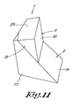
- an improved prism assembly comprises a total internal reflection (TIR) assembly 1, for redirecting an incoming lightbeam A, a color prism assembly 7, for splitting the incoming lightbeam A into spectral bands B, C and D, and at least one reflection light valve for redirecting and recombining the spectral bands B, C and D to form an outgoing lightbeam E, whereby said total internal reflection assembly 1 shows a back surface 13 and said color prism assembly shows a front surface 14 facing said back surface 13 and being parallel therewith, wherein said back surface 13 forms an angle with a general plane defined by the incoming and the outgoing lightbeams A and E, which is different from 90°.
- TIR total internal reflection
- said prism assembly is provided with three reflection light valves, in the form of DMD' s 4 to 6, respectively one for each color red, green and blue.
- DMD' s 4 to 6 respectively one for each color red, green and blue.
- said total internal reflection assembly 1 consists of a first prism 2 and a second prism 3, whereby said first prism 2 and said second prism 3 are spaced apart by a thin gap, for example in the form of an air gap.
- said first prism 2 and said second prism 3 have at least one parallel surface.
- said back surface 13 is at least partially formed by a surface of said first prism 2. It is clear that it is also possible that said back surface 13 is at least partially formed by a surface of said second prism 3.
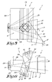
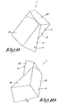
- a total internal reflection assembly 1 preferably comprises a base surface 15 which is connected to said back surface 13, enclosing an angle therewith and which is perpendicular to the general plane defined by the incoming and the outgoing lightbeams A and E; and a redirecting surface 16, connecting said back surface 13 with said base surface 15, which is perpendicular to the general plane defined by the incoming and the outgoing lightbeams A and E.
- total internal prism assembly 1 as shown figures 9 to 11 , further comprises two side surfaces 17 and 18 which are connected to said back surface 13 and which diverge with respect thereto; and wherein said redirecting surface 16 is connected to said side surfaces 17 and 18.
- Said second prism 3 preferably comprises a first surface 19 which is parallel to said redirecting surface 16 of said first prism 2; and a front surface 20, being perpendicular to the general plane defined by the incoming and the outgoing lightbeams A and E.
- Said second prism 3 of the improved prism assembly according to the invention further comprises two side surfaces 21 and 22 which are connected to said first surface 19 of the second prism 3 and which are provided in the same face as the side surfaces 17 and 18 of the first prism 2.
- said second prism 3 further comprises an upper surface 23, extending between said front surface 20 and said side surfaces 21 and 22 of the second prism 3, whereby said upper surface 23 of the second prism 3 and said base surface 15 of the first prism 2 diverge with respect to each other.
- said color prism assembly 7 consists of three prisms 8 to 10 for different colors, and more specific a red prism 8, a green prism 9 and a blue prism 10.
- Said three prisms 8 to 10 of the color prism assembly 7 are preferably formed by an upstanding first prism 9 in the form of a quadrangular prism, which has a first upstanding surface 24 and two side surfaces 25 and 26, perpendicular to said first surface 24 and a second surface 27 extending between said side surfaces 25 and 26 and enclosing an angle therewith, differing from 90°; and two triangular prisms 8 and 10, the first triangular prism 8 of which a first side 28 opposes said second face 27 of the quadrangular first prism 9 and the second triangular prism 10 of which a side 29 opposes a second side 30 of said first triangular prism 8.
- said quadrangular prism 9 and said triangular prisms 8 and 10 are spaced apart from each other, defining gaps therebetween.
- the improved prism assembly according to the invention has five prisms 2, 3, 8, 9 and 10 but combines the technical advantages of both existing 5-element and 6-element prism assemblies, at a cost point between the two.
- the proposed new prism assembly combines the blue, red and green prism 8, 9 and 10 with the 6-element design od figures.3 and 4 .
- the combination of the sixth element 12 of the 6-element design and the two prisms 2 and 3 of the TIR-prism assembly 1 is replaced with a more compact assembly of two prisms 2 and 3.
- the first prism 2 of the total internal reflection assembly 1 takes over the function of the sixth element 12.
- the new prism assembly comprises five prisms 2, 3, 8, 9 and 10, but the shape of the two prisms 2 and 3 of the total internal reflection assembly 1 is slightly more complex than in the two classical designs. There are fewer right angles, but the number of surfaces and edges are the same. Thus, the cost of the new design should be only slightly larger than the 5-element prism as shown in figures 1 and 2 .
Landscapes
- Physics & Mathematics (AREA)
- General Physics & Mathematics (AREA)
- Optics & Photonics (AREA)
- Engineering & Computer Science (AREA)
- Multimedia (AREA)
- Signal Processing (AREA)
- Optical Elements Other Than Lenses (AREA)
- Projection Apparatus (AREA)
- Color Television Image Signal Generators (AREA)
- Mounting And Adjusting Of Optical Elements (AREA)
- Mechanical Light Control Or Optical Switches (AREA)
- Holo Graphy (AREA)
Claims (17)
- Verbesserte Philips-Prismenanordnung, bestehend aus fünf Prismen, zur Anwendung in optischen Geräten, welche eine Totalreflexions(TIR)-Anordnung (1) zum Umlenken eines eintretenden Lichtstrahls (A) umfasst, eine Farbprismenanordnung (7) zum Aufteilen des eintretenden Lichtstrahls (A) in Spektralbänder (B, C und D), und mindestens ein Reflexionslichtventil zum Umlenken und Rekombinieren der Spektralbänder (B, C und D) zur Bildung eines austretenden Lichtstrahls (E), wobei die Totalreflexionsanordnung (1) eine Rückseite (13) aufweist und die Farbprismenanordnung (7) eine Vorderseite (14) aufweist, die der Rückseite (13) zugewandt und parallel dazu ist, dadurch gekennzeichnet, dass die Rückseite (13) mit einer durch den eintretenden und den austretenden Lichtstrahl (A und E) definierten generellen Ebene einen Winkel bildet, der von 90° verschieden ist.
- Verbesserte Prismenanordnung nach Anspruch 1, dadurch gekennzeichnet, dass die Totalreflexionsanordnung (1) aus einem ersten Prisma (2) und einem zweiten Prisma (3) besteht.
- Verbesserte Prismenanordnung nach Anspruch 2, dadurch gekennzeichnet, dass das erste Prisma (2) und das zweite Prisma (3) durch einen dünnen Spalt voneinander beabstandet sind.
- Verbesserte Prismenanordnung nach Anspruch 3, dadurch gekennzeichnet, dass der Spalt ein Luftspalt ist.
- Verbesserte Prismenanordnung nach Anspruch 2, dadurch gekennzeichnet, dass das erste Prisma (2) und das zweite Prisma (3) mindestens eine parallele Fläche (16 und 19) haben.
- Verbesserte Prismenanordnung nach Anspruch 2, dadurch gekennzeichnet, dass das erste Prisma (2) umfasst:- eine Grundfläche (15), die mit der Rückseite (13) verbunden ist und einen Winkel damit einschließt, und die senkrecht zu der durch den eintretenden und den austretenden Lichtstrahl (A und E) definierten generellen Ebene ist;- eine Umlenkfläche (16), die die Rückseite (13) mit der Grundfläche (15) verbindet, die senkrecht zu der durch den eintretenden und den austretenden Lichtstrahl (A und E) definierten generellen Ebene ist.
- Verbesserte Prismenanordnung nach Anspruch 6, dadurch gekennzeichnet, dass das erste Prisma (2) weiter zwei Seitenflächen (17 und 18) umfasst, die mit der Rückseite (13) verbunden sind und die bezüglich dieser divergieren; und wobei die Umlenkfläche (16) mit den Seitenflächen (17 und 18) verbunden ist.
- Verbesserte Prismenanordnung nach Anspruch 6, dadurch gekennzeichnet, dass das zweite Prisma (3) umfasst:- eine erste Fläche (19), die parallel zu der Umlenkfläche (16) des ersten Prismas (2) ist; und- eine Vorderseite (20), die senkrecht zu der durch den eintretenden und den austretenden Lichtstrahl (A und E) definierten generellen Ebene ist.
- Verbesserte Prismenanordnung nach Anspruch 8, dadurch gekennzeichnet, dass das zweite Prisma (3) weiter zwei Seitenflächen (21 und 22) umfasst, die mit der ersten Fläche (19) des zweiten Prismas (3) verbunden sind und die in derselben Seite wie die Seitenflächen (17 und 18) des ersten Prismas (2) vorgesehen sind.
- Verbesserte Prismenanordnung nach Anspruch 9, dadurch gekennzeichnet, dass das zweite Prisma (3) weiter eine Oberseite (23) umfasst, die sich zwischen der Vorderseite (20) und den Seitenflächen (21 und 22) des zweiten Prismas (3) erstreckt.
- Verbesserte Prismenanordnung nach Anspruch 10, dadurch gekennzeichnet, dass die Oberseite (23) des zweiten Prismas (3) und die Grundfläche (15) des ersten Prismas (2) in Bezug zueinander divergieren.
- Verbesserte Prismenanordnung nach Anspruch 1, dadurch gekennzeichnet, dass die Farbprismenanordnung (7) aus drei Prismen (8, 9 und 10) für verschiedene Farben besteht.
- Verbesserte Prismenanordnung nach Anspruch 12, dadurch gekennzeichnet, dass die Farbprismenanordnung (7) ein rotes Prisma (8), ein grünes Prisma (9) und ein blaues Prisma (10) umfasst.
- Verbesserte Prismenanordnung nach Anspruch 12, dadurch gekennzeichnet, dass die drei Prismen (8, 9 und 10) der Farbprismenanordnung (7) gebildet werden von:- einem aufrechtstehenden ersten Prisma (9) in Form eines vierseitigen Prismas, das eine erste aufrechte Fläche (24) und zwei Seitenflächen (25 und 26) senkrecht zu der ersten Fläche (24) und eine zweite Fläche (27), die sich zwischen den Seitenflächen (25 und 26) erstreckt und einen sich von 90° unterscheidenden Winkel damit einschließt, aufweist;- zwei dreiseitigen Prismen (8 und 10), dem ersten dreiseitigen Prisma (8), wovon eine erste Seite (28) der zweiten Seite (27) des vierseitigen Prismas gegenübersteht, und dem zweiten dreiseitigen Prisma (10), wovon eine Seite (29) einer zweiten Seite (30) des ersten dreiseitigen Prismas (8) gegenübersteht.
- Verbesserte Prismenanordnung nach Anspruch 14, dadurch gekennzeichnet, dass die vierseitigen und die dreiseitigen Prismen (8, 9 und 10) voneinander beabstandet sind, wobei sie Spalten hierzwischen definieren.
- Projektor, umfassend eine verbesserte Prismenanordnung gemäß einem der Ansprüche 1 bis 15.
- Projektor nach Anspruch 16, dadurch gekennzeichnet, dass der Projektor ein DLP-Projektor ist.
Applications Claiming Priority (1)
| Application Number | Priority Date | Filing Date | Title |
|---|---|---|---|
| US60612504P | 2004-09-01 | 2004-09-01 |
Publications (2)
| Publication Number | Publication Date |
|---|---|
| EP1632805A1 EP1632805A1 (de) | 2006-03-08 |
| EP1632805B1 true EP1632805B1 (de) | 2008-10-08 |
Family
ID=34938392
Family Applications (2)
| Application Number | Title | Priority Date | Filing Date |
|---|---|---|---|
| EP05076840A Expired - Lifetime EP1632804B1 (de) | 2004-09-01 | 2005-08-09 | Prismenanordnung |
| EP05076854A Expired - Lifetime EP1632805B1 (de) | 2004-09-01 | 2005-08-10 | Eine verbesserte Prismenanordnung für einen Projektor |
Family Applications Before (1)
| Application Number | Title | Priority Date | Filing Date |
|---|---|---|---|
| EP05076840A Expired - Lifetime EP1632804B1 (de) | 2004-09-01 | 2005-08-09 | Prismenanordnung |
Country Status (7)
| Country | Link |
|---|---|
| US (2) | US7396132B2 (de) |
| EP (2) | EP1632804B1 (de) |
| JP (2) | JP2006072365A (de) |
| AT (2) | ATE397759T1 (de) |
| DE (2) | DE602005007299D1 (de) |
| DK (1) | DK1632804T3 (de) |
| ES (1) | ES2309651T3 (de) |
Cited By (1)
| Publication number | Priority date | Publication date | Assignee | Title |
|---|---|---|---|---|
| LU103175B1 (en) | 2023-07-14 | 2025-01-14 | Barco Nv | A prism assembly for use in a digital light processing system |
Families Citing this family (60)
| Publication number | Priority date | Publication date | Assignee | Title |
|---|---|---|---|---|
| US7123216B1 (en) | 1994-05-05 | 2006-10-17 | Idc, Llc | Photonic MEMS and structures |
| US8928967B2 (en) | 1998-04-08 | 2015-01-06 | Qualcomm Mems Technologies, Inc. | Method and device for modulating light |
| WO1999052006A2 (en) | 1998-04-08 | 1999-10-14 | Etalon, Inc. | Interferometric modulation of radiation |
| US7532377B2 (en) * | 1998-04-08 | 2009-05-12 | Idc, Llc | Movable micro-electromechanical device |
| WO2003007049A1 (en) | 1999-10-05 | 2003-01-23 | Iridigm Display Corporation | Photonic mems and structures |
| US6574033B1 (en) | 2002-02-27 | 2003-06-03 | Iridigm Display Corporation | Microelectromechanical systems device and method for fabricating same |
| US8085462B2 (en) * | 2003-12-29 | 2011-12-27 | Max Mayer | Superposition method using a pair of stereo-isomeric micro electro mechanical systems (MEMSs) |
| US7476327B2 (en) | 2004-05-04 | 2009-01-13 | Idc, Llc | Method of manufacture for microelectromechanical devices |
| KR101354520B1 (ko) | 2004-07-29 | 2014-01-21 | 퀄컴 엠이엠에스 테크놀로지스, 인크. | 간섭 변조기의 미소기전 동작을 위한 시스템 및 방법 |
| ATE397759T1 (de) * | 2004-09-01 | 2008-06-15 | Barco Nv | Prismenanordnung |
| US7936497B2 (en) | 2004-09-27 | 2011-05-03 | Qualcomm Mems Technologies, Inc. | MEMS device having deformable membrane characterized by mechanical persistence |
| US8008736B2 (en) | 2004-09-27 | 2011-08-30 | Qualcomm Mems Technologies, Inc. | Analog interferometric modulator device |
| US7420725B2 (en) | 2004-09-27 | 2008-09-02 | Idc, Llc | Device having a conductive light absorbing mask and method for fabricating same |
| US7289259B2 (en) | 2004-09-27 | 2007-10-30 | Idc, Llc | Conductive bus structure for interferometric modulator array |
| US7302157B2 (en) * | 2004-09-27 | 2007-11-27 | Idc, Llc | System and method for multi-level brightness in interferometric modulation |
| US7321456B2 (en) * | 2004-09-27 | 2008-01-22 | Idc, Llc | Method and device for corner interferometric modulation |
| US7893919B2 (en) * | 2004-09-27 | 2011-02-22 | Qualcomm Mems Technologies, Inc. | Display region architectures |
| US7327510B2 (en) * | 2004-09-27 | 2008-02-05 | Idc, Llc | Process for modifying offset voltage characteristics of an interferometric modulator |
| US7304784B2 (en) | 2004-09-27 | 2007-12-04 | Idc, Llc | Reflective display device having viewable display on both sides |
| US7719500B2 (en) | 2004-09-27 | 2010-05-18 | Qualcomm Mems Technologies, Inc. | Reflective display pixels arranged in non-rectangular arrays |
| US7630119B2 (en) | 2004-09-27 | 2009-12-08 | Qualcomm Mems Technologies, Inc. | Apparatus and method for reducing slippage between structures in an interferometric modulator |
| US7554714B2 (en) | 2004-09-27 | 2009-06-30 | Idc, Llc | Device and method for manipulation of thermal response in a modulator |
| US7527995B2 (en) | 2004-09-27 | 2009-05-05 | Qualcomm Mems Technologies, Inc. | Method of making prestructure for MEMS systems |
| US7372613B2 (en) * | 2004-09-27 | 2008-05-13 | Idc, Llc | Method and device for multistate interferometric light modulation |
| US7564612B2 (en) | 2004-09-27 | 2009-07-21 | Idc, Llc | Photonic MEMS and structures |
| US7944599B2 (en) | 2004-09-27 | 2011-05-17 | Qualcomm Mems Technologies, Inc. | Electromechanical device with optical function separated from mechanical and electrical function |
| JP2009519494A (ja) * | 2005-12-15 | 2009-05-14 | コーニンクレッカ フィリップス エレクトロニクス エヌ ヴィ | Memsスキャナシステム及び方法 |
| US7916980B2 (en) | 2006-01-13 | 2011-03-29 | Qualcomm Mems Technologies, Inc. | Interconnect structure for MEMS device |
| US7550810B2 (en) | 2006-02-23 | 2009-06-23 | Qualcomm Mems Technologies, Inc. | MEMS device having a layer movable at asymmetric rates |
| US7649671B2 (en) | 2006-06-01 | 2010-01-19 | Qualcomm Mems Technologies, Inc. | Analog interferometric modulator device with electrostatic actuation and release |
| US7471442B2 (en) | 2006-06-15 | 2008-12-30 | Qualcomm Mems Technologies, Inc. | Method and apparatus for low range bit depth enhancements for MEMS display architectures |
| US7835061B2 (en) | 2006-06-28 | 2010-11-16 | Qualcomm Mems Technologies, Inc. | Support structures for free-standing electromechanical devices |
| US7385744B2 (en) | 2006-06-28 | 2008-06-10 | Qualcomm Mems Technologies, Inc. | Support structure for free-standing MEMS device and methods for forming the same |
| US7527998B2 (en) | 2006-06-30 | 2009-05-05 | Qualcomm Mems Technologies, Inc. | Method of manufacturing MEMS devices providing air gap control |
| GB0711641D0 (en) * | 2007-06-18 | 2007-07-25 | Barco Nv | Dual TIR prism architecture to enhance DLP projectors |
| JP5042168B2 (ja) | 2008-08-29 | 2012-10-03 | 株式会社リコー | 画像投射装置、並びに、プリズム、プリズム系、及び投射光学系 |
| TWI392955B (zh) * | 2008-09-10 | 2013-04-11 | Delta Electronics Inc | 光線導引模組及包含該光線導引模組之投影裝置 |
| JP2010276663A (ja) * | 2009-05-26 | 2010-12-09 | Konica Minolta Opto Inc | プリズムユニット |
| KR20130100232A (ko) | 2010-04-09 | 2013-09-10 | 퀄컴 엠이엠에스 테크놀로지스, 인크. | 전기 기계 디바이스의 기계층 및 그 형성 방법 |
| US8342690B2 (en) * | 2010-04-29 | 2013-01-01 | Eastman Kodak Company | Off-state light baffle for digital projection |
| US9134527B2 (en) | 2011-04-04 | 2015-09-15 | Qualcomm Mems Technologies, Inc. | Pixel via and methods of forming the same |
| US8963159B2 (en) | 2011-04-04 | 2015-02-24 | Qualcomm Mems Technologies, Inc. | Pixel via and methods of forming the same |
| DE102011102132A1 (de) | 2011-05-19 | 2012-11-22 | blnsight3D GmbH | Mehrkanalanzeige mit MOEMS und Verfahren der Superposition nicht-normal abgestrahlter Bildstrahlen in Mehrkanalanzeigen mit MOEMS |
| US9877001B2 (en) | 2013-11-05 | 2018-01-23 | Konica Minolta, Inc. | Three-plate optical system and projector |
| KR102153045B1 (ko) * | 2013-12-04 | 2020-09-07 | 삼성전자주식회사 | 파장 분리 소자 및 이를 포함하는 3차원 영상 획득 장치 |
| JP6388028B2 (ja) * | 2014-06-13 | 2018-09-12 | コニカミノルタ株式会社 | 画像投影ユニットおよび画像投射装置 |
| JP2016075825A (ja) * | 2014-10-07 | 2016-05-12 | パナソニックIpマネジメント株式会社 | 色分解プリズム及び撮像装置 |
| EP4002006A1 (de) | 2014-12-31 | 2022-05-25 | Dolby Laboratories Licensing Corporation | Verbesserte integrationsstabanordnungen für bildprojektoren |
| WO2017094690A1 (ja) * | 2015-12-04 | 2017-06-08 | コニカミノルタ株式会社 | 投射型表示装置とその設計方法 |
| WO2018087756A1 (en) * | 2016-11-08 | 2018-05-17 | Lumus Ltd | Light-guide device with optical cutoff edge and corresponding production methods |
| WO2019077643A1 (ja) | 2017-10-16 | 2019-04-25 | オリンパス株式会社 | 内視鏡および内視鏡システム |
| US10599027B2 (en) | 2017-11-29 | 2020-03-24 | Texas Instruments Incorporated | Projector with multiple spatial light modulators prisms and light sources |
| WO2020090318A1 (ja) * | 2018-11-01 | 2020-05-07 | パナソニックIpマネジメント株式会社 | 光学ユニット及び投影装置 |
| JP6891870B2 (ja) | 2018-12-28 | 2021-06-18 | セイコーエプソン株式会社 | プロジェクター |
| TWI798391B (zh) * | 2019-03-20 | 2023-04-11 | 揚明光學股份有限公司 | 光路調整機構及其製造方法 |
| JP7417892B2 (ja) * | 2019-12-26 | 2024-01-19 | パナソニックIpマネジメント株式会社 | 表示装置および投写装置 |
| US12432323B2 (en) * | 2020-09-01 | 2025-09-30 | Fusao Ishii | Optics for projection display |
| JP7196897B2 (ja) * | 2020-11-30 | 2022-12-27 | コニカミノルタ株式会社 | 光学ユニット及びそれを備えたプロジェクター |
| CN113466979B (zh) * | 2021-07-01 | 2023-05-16 | 希烽光电科技(南京)有限公司 | 一种光电监控用双反射棱镜及其光电监控组件 |
| CN114322944B (zh) * | 2021-12-24 | 2023-09-12 | 中国科学院长春光学精密机械与物理研究所 | 同轴折返式导航与光谱一体化光学系统 |
Family Cites Families (25)
| Publication number | Priority date | Publication date | Assignee | Title |
|---|---|---|---|---|
| JPS5879201A (ja) * | 1981-10-19 | 1983-05-13 | フオ−ド・エ−ロスペイス・アンド・コミユニケイシヨンズ・コ−ポレイシヨン | 内部全反射素子のための防護された表面 |
| US6873639B2 (en) * | 1993-05-28 | 2005-03-29 | Tong Zhang | Multipass geometry and constructions for diode-pumped solid-state lasers and fiber lasers, and for optical amplifier and detector |
| JP3336794B2 (ja) * | 1995-02-20 | 2002-10-21 | セイコーエプソン株式会社 | 偏光照明装置およびそれを用いた投写型表示装置 |
| DE69534037T2 (de) * | 1994-12-28 | 2005-12-29 | Seiko Epson Corp. | Beleuchtungsvorrichtung mit polarisiertem licht und projektionsanzeigevorrichtung |
| JPH11505334A (ja) * | 1995-05-11 | 1999-05-18 | ディジタル プロジェクション リミテッド | 投影装置 |
| JP3290091B2 (ja) * | 1997-03-31 | 2002-06-10 | シャープ株式会社 | 投影型画像表示装置 |
| US6249387B1 (en) * | 1998-05-13 | 2001-06-19 | Texas Instruments Incorporated | Stable enhanced contrast optical system for high resolution displays |
| TW403854B (en) | 1998-11-10 | 2000-09-01 | Seiko Epson Corp | Projection type display device |
| JP2003522966A (ja) * | 1998-12-22 | 2003-07-29 | ヴァリンテリジェント(ビーヴイアイ)リミテッド | 反射型ライトバルブ用光学アセンブリ |
| JP3065068B1 (ja) * | 1999-03-05 | 2000-07-12 | ミノルタ株式会社 | 投影光学系 |
| US6560048B1 (en) * | 1999-09-30 | 2003-05-06 | Mitsubishi Denki Kabushiki Kaisha | Prism having two inner surfaces and outer shape regarded as plane parallel plate |
| JP3967874B2 (ja) * | 1999-09-30 | 2007-08-29 | 三菱電機株式会社 | プリズム、投写光学系及び投写型表示装置 |
| EP1193982A1 (de) * | 2000-09-20 | 2002-04-03 | Barco N.V. | Projektor mit einem Kühlsystem für die Lichtmodulatoren |
| JP2002287248A (ja) * | 2001-03-27 | 2002-10-03 | Minolta Co Ltd | カラー投影装置 |
| US6672721B2 (en) * | 2001-06-11 | 2004-01-06 | 3M Innovative Properties Company | Projection system having low astigmatism |
| JP2003029150A (ja) * | 2001-07-13 | 2003-01-29 | Olympus Optical Co Ltd | 光学特性可変光学素子を含む光学系及び光学装置 |
| US6999237B2 (en) * | 2001-09-12 | 2006-02-14 | Lightmaster Systems, Inc. | Method and apparatus for configuration and assembly of a video projection light management system |
| US7207678B2 (en) * | 2001-12-31 | 2007-04-24 | Texas Instruments Incorporated | Prism for high contrast projection |
| US6959990B2 (en) * | 2001-12-31 | 2005-11-01 | Texas Instruments Incorporated | Prism for high contrast projection |
| US6644813B1 (en) * | 2002-01-04 | 2003-11-11 | Raytheon Company | Four prism color management system for projection systems |
| US6796663B2 (en) * | 2002-02-11 | 2004-09-28 | Lightmaster Systems, Inc. | Method and apparatus for mounting liquid crystal on silicon (LCoS) and other sensitive devices |
| JP3970067B2 (ja) * | 2002-03-19 | 2007-09-05 | 株式会社リコー | 光路切替素子、空間光変調器および画像表示装置 |
| TW594052B (en) * | 2003-03-18 | 2004-06-21 | Asia Optical Co Inc | Optical prism set and range measurement device using the same |
| US20050162616A1 (en) * | 2004-01-23 | 2005-07-28 | Hewlett-Packard Co. | System and method of contrast enhancement in digital projectors |
| ATE397759T1 (de) * | 2004-09-01 | 2008-06-15 | Barco Nv | Prismenanordnung |
-
2005
- 2005-08-09 AT AT05076840T patent/ATE397759T1/de not_active IP Right Cessation
- 2005-08-09 ES ES05076840T patent/ES2309651T3/es not_active Expired - Lifetime
- 2005-08-09 EP EP05076840A patent/EP1632804B1/de not_active Expired - Lifetime
- 2005-08-09 DK DK05076840T patent/DK1632804T3/da active
- 2005-08-09 DE DE602005007299T patent/DE602005007299D1/de not_active Expired - Lifetime
- 2005-08-10 EP EP05076854A patent/EP1632805B1/de not_active Expired - Lifetime
- 2005-08-10 AT AT05076854T patent/ATE410713T1/de not_active IP Right Cessation
- 2005-08-10 DE DE602005010171T patent/DE602005010171D1/de not_active Expired - Lifetime
- 2005-08-25 US US11/210,749 patent/US7396132B2/en active Active
- 2005-08-25 US US11/210,744 patent/US7576932B2/en not_active Expired - Lifetime
- 2005-08-31 JP JP2005252643A patent/JP2006072365A/ja not_active Ceased
- 2005-08-31 JP JP2005252597A patent/JP5174317B2/ja not_active Expired - Lifetime
Cited By (2)
| Publication number | Priority date | Publication date | Assignee | Title |
|---|---|---|---|---|
| LU103175B1 (en) | 2023-07-14 | 2025-01-14 | Barco Nv | A prism assembly for use in a digital light processing system |
| WO2025016915A1 (en) | 2023-07-14 | 2025-01-23 | Barco N.V. | A prism assembly for use in a digital light processing system |
Also Published As
| Publication number | Publication date |
|---|---|
| DK1632804T3 (da) | 2008-09-29 |
| EP1632804A1 (de) | 2006-03-08 |
| EP1632805A1 (de) | 2006-03-08 |
| EP1632804B1 (de) | 2008-06-04 |
| US20060044654A1 (en) | 2006-03-02 |
| ATE410713T1 (de) | 2008-10-15 |
| ES2309651T3 (es) | 2008-12-16 |
| ATE397759T1 (de) | 2008-06-15 |
| JP2006079080A (ja) | 2006-03-23 |
| DE602005007299D1 (de) | 2008-07-17 |
| US7396132B2 (en) | 2008-07-08 |
| US7576932B2 (en) | 2009-08-18 |
| DE602005010171D1 (de) | 2008-11-20 |
| JP2006072365A (ja) | 2006-03-16 |
| JP5174317B2 (ja) | 2013-04-03 |
| US20060044521A1 (en) | 2006-03-02 |
Similar Documents
| Publication | Publication Date | Title |
|---|---|---|
| EP1632805B1 (de) | Eine verbesserte Prismenanordnung für einen Projektor | |
| US7165867B2 (en) | Systems and methods for integrating light | |
| US7863553B2 (en) | Optical processing structure for a digital light processing projection device having plural total internal reflection prisms as light reflecting devices | |
| JP4707453B2 (ja) | 画像投射装置 | |
| MXPA06013030A (es) | Sistema de iluminacion con apertura no radialmente simetrica. | |
| CN208547803U (zh) | 照明系统以及投影装置 | |
| JP2005338828A (ja) | 画像投射装置 | |
| CN111812934A (zh) | 一种单直角棱镜led微型投影照明系统 | |
| US6623121B2 (en) | Polarization beam splitter, optical device for projection type display device, projection type display device, and polarization beam splitter manufacturing method | |
| US9690180B2 (en) | Prism group and projection apparatus | |
| US6885403B2 (en) | Color separation beam splitter for projectors | |
| EP1471746A2 (de) | Projektionseinrichtung und Lamplichtquellesystem für eine solche einrichtung | |
| US7210788B2 (en) | Color prism and projection-type image display apparatus employing the same | |
| US10969672B2 (en) | Light source device and projection display apparatus using light source device | |
| US20020141070A1 (en) | Color projection device | |
| US7167314B2 (en) | Projector with total cross total internal reflection (TIR) prisms | |
| KR101713342B1 (ko) | 프로젝션 시스템 | |
| EP1627527A1 (de) | Videoprojektor-beleuchtungssystem mit einer oder mehreren leuchtdiodenmatrizen | |
| CN110764349B (zh) | 投影系统 | |
| CN115708004A (zh) | 一种镜头系统和投影装置 | |
| KR20090028852A (ko) | 프로젝션 시스템 | |
| JP2000147658A (ja) | 映像投射装置 | |
| JP2016099585A (ja) | 光学装置および画像投射装置 | |
| CN111123627B (zh) | 投影装置及放映机 | |
| JP2005165137A (ja) | 照明光学系および画像表示装置 |
Legal Events
| Date | Code | Title | Description |
|---|---|---|---|
| PUAI | Public reference made under article 153(3) epc to a published international application that has entered the european phase |
Free format text: ORIGINAL CODE: 0009012 |
|
| AK | Designated contracting states |
Kind code of ref document: A1 Designated state(s): AT BE BG CH CY CZ DE DK EE ES FI FR GB GR HU IE IS IT LI LT LU LV MC NL PL PT RO SE SI SK TR |
|
| AX | Request for extension of the european patent |
Extension state: AL BA HR MK YU |
|
| AKX | Designation fees paid | ||
| 17P | Request for examination filed |
Effective date: 20060906 |
|
| RBV | Designated contracting states (corrected) |
Designated state(s): AT BE BG CH CY CZ DE DK EE ES FI FR GB GR HU IE IS IT LI LT LU LV MC NL PL PT RO SE SI SK TR |
|
| 17Q | First examination report despatched |
Effective date: 20061109 |
|
| REG | Reference to a national code |
Ref country code: DE Ref legal event code: 8566 |
|
| GRAP | Despatch of communication of intention to grant a patent |
Free format text: ORIGINAL CODE: EPIDOSNIGR1 |
|
| GRAS | Grant fee paid |
Free format text: ORIGINAL CODE: EPIDOSNIGR3 |
|
| GRAA | (expected) grant |
Free format text: ORIGINAL CODE: 0009210 |
|
| AK | Designated contracting states |
Kind code of ref document: B1 Designated state(s): AT BE BG CH CY CZ DE DK EE ES FI FR GB GR HU IE IS IT LI LT LU LV MC NL PL PT RO SE SI SK TR |
|
| REG | Reference to a national code |
Ref country code: GB Ref legal event code: FG4D |
|
| REG | Reference to a national code |
Ref country code: CH Ref legal event code: EP |
|
| REG | Reference to a national code |
Ref country code: IE Ref legal event code: FG4D |
|
| REF | Corresponds to: |
Ref document number: 602005010171 Country of ref document: DE Date of ref document: 20081120 Kind code of ref document: P |
|
| PG25 | Lapsed in a contracting state [announced via postgrant information from national office to epo] |
Ref country code: SI Free format text: LAPSE BECAUSE OF FAILURE TO SUBMIT A TRANSLATION OF THE DESCRIPTION OR TO PAY THE FEE WITHIN THE PRESCRIBED TIME-LIMIT Effective date: 20081008 |
|
| PG25 | Lapsed in a contracting state [announced via postgrant information from national office to epo] |
Ref country code: AT Free format text: LAPSE BECAUSE OF FAILURE TO SUBMIT A TRANSLATION OF THE DESCRIPTION OR TO PAY THE FEE WITHIN THE PRESCRIBED TIME-LIMIT Effective date: 20081008 Ref country code: BG Free format text: LAPSE BECAUSE OF FAILURE TO SUBMIT A TRANSLATION OF THE DESCRIPTION OR TO PAY THE FEE WITHIN THE PRESCRIBED TIME-LIMIT Effective date: 20090108 Ref country code: LT Free format text: LAPSE BECAUSE OF FAILURE TO SUBMIT A TRANSLATION OF THE DESCRIPTION OR TO PAY THE FEE WITHIN THE PRESCRIBED TIME-LIMIT Effective date: 20081008 Ref country code: ES Free format text: LAPSE BECAUSE OF FAILURE TO SUBMIT A TRANSLATION OF THE DESCRIPTION OR TO PAY THE FEE WITHIN THE PRESCRIBED TIME-LIMIT Effective date: 20090119 |
|
| PG25 | Lapsed in a contracting state [announced via postgrant information from national office to epo] |
Ref country code: PL Free format text: LAPSE BECAUSE OF FAILURE TO SUBMIT A TRANSLATION OF THE DESCRIPTION OR TO PAY THE FEE WITHIN THE PRESCRIBED TIME-LIMIT Effective date: 20081008 Ref country code: LV Free format text: LAPSE BECAUSE OF FAILURE TO SUBMIT A TRANSLATION OF THE DESCRIPTION OR TO PAY THE FEE WITHIN THE PRESCRIBED TIME-LIMIT Effective date: 20081008 Ref country code: PT Free format text: LAPSE BECAUSE OF FAILURE TO SUBMIT A TRANSLATION OF THE DESCRIPTION OR TO PAY THE FEE WITHIN THE PRESCRIBED TIME-LIMIT Effective date: 20090218 Ref country code: FI Free format text: LAPSE BECAUSE OF FAILURE TO SUBMIT A TRANSLATION OF THE DESCRIPTION OR TO PAY THE FEE WITHIN THE PRESCRIBED TIME-LIMIT Effective date: 20081008 Ref country code: IS Free format text: LAPSE BECAUSE OF FAILURE TO SUBMIT A TRANSLATION OF THE DESCRIPTION OR TO PAY THE FEE WITHIN THE PRESCRIBED TIME-LIMIT Effective date: 20090208 |
|
| PG25 | Lapsed in a contracting state [announced via postgrant information from national office to epo] |
Ref country code: RO Free format text: LAPSE BECAUSE OF FAILURE TO SUBMIT A TRANSLATION OF THE DESCRIPTION OR TO PAY THE FEE WITHIN THE PRESCRIBED TIME-LIMIT Effective date: 20081008 Ref country code: EE Free format text: LAPSE BECAUSE OF FAILURE TO SUBMIT A TRANSLATION OF THE DESCRIPTION OR TO PAY THE FEE WITHIN THE PRESCRIBED TIME-LIMIT Effective date: 20081008 Ref country code: DK Free format text: LAPSE BECAUSE OF FAILURE TO SUBMIT A TRANSLATION OF THE DESCRIPTION OR TO PAY THE FEE WITHIN THE PRESCRIBED TIME-LIMIT Effective date: 20081008 |
|
| PLBE | No opposition filed within time limit |
Free format text: ORIGINAL CODE: 0009261 |
|
| STAA | Information on the status of an ep patent application or granted ep patent |
Free format text: STATUS: NO OPPOSITION FILED WITHIN TIME LIMIT |
|
| PG25 | Lapsed in a contracting state [announced via postgrant information from national office to epo] |
Ref country code: IT Free format text: LAPSE BECAUSE OF FAILURE TO SUBMIT A TRANSLATION OF THE DESCRIPTION OR TO PAY THE FEE WITHIN THE PRESCRIBED TIME-LIMIT Effective date: 20081008 Ref country code: SE Free format text: LAPSE BECAUSE OF FAILURE TO SUBMIT A TRANSLATION OF THE DESCRIPTION OR TO PAY THE FEE WITHIN THE PRESCRIBED TIME-LIMIT Effective date: 20090108 Ref country code: CZ Free format text: LAPSE BECAUSE OF FAILURE TO SUBMIT A TRANSLATION OF THE DESCRIPTION OR TO PAY THE FEE WITHIN THE PRESCRIBED TIME-LIMIT Effective date: 20081008 |
|
| 26N | No opposition filed |
Effective date: 20090709 |
|
| PG25 | Lapsed in a contracting state [announced via postgrant information from national office to epo] |
Ref country code: SK Free format text: LAPSE BECAUSE OF FAILURE TO SUBMIT A TRANSLATION OF THE DESCRIPTION OR TO PAY THE FEE WITHIN THE PRESCRIBED TIME-LIMIT Effective date: 20081008 |
|
| PG25 | Lapsed in a contracting state [announced via postgrant information from national office to epo] |
Ref country code: MC Free format text: LAPSE BECAUSE OF NON-PAYMENT OF DUE FEES Effective date: 20090831 |
|
| REG | Reference to a national code |
Ref country code: CH Ref legal event code: PL |
|
| PG25 | Lapsed in a contracting state [announced via postgrant information from national office to epo] |
Ref country code: LI Free format text: LAPSE BECAUSE OF NON-PAYMENT OF DUE FEES Effective date: 20090831 Ref country code: CH Free format text: LAPSE BECAUSE OF NON-PAYMENT OF DUE FEES Effective date: 20090831 |
|
| PG25 | Lapsed in a contracting state [announced via postgrant information from national office to epo] |
Ref country code: IE Free format text: LAPSE BECAUSE OF NON-PAYMENT OF DUE FEES Effective date: 20090810 |
|
| PG25 | Lapsed in a contracting state [announced via postgrant information from national office to epo] |
Ref country code: GR Free format text: LAPSE BECAUSE OF FAILURE TO SUBMIT A TRANSLATION OF THE DESCRIPTION OR TO PAY THE FEE WITHIN THE PRESCRIBED TIME-LIMIT Effective date: 20090109 |
|
| PG25 | Lapsed in a contracting state [announced via postgrant information from national office to epo] |
Ref country code: LU Free format text: LAPSE BECAUSE OF NON-PAYMENT OF DUE FEES Effective date: 20090810 |
|
| PG25 | Lapsed in a contracting state [announced via postgrant information from national office to epo] |
Ref country code: HU Free format text: LAPSE BECAUSE OF FAILURE TO SUBMIT A TRANSLATION OF THE DESCRIPTION OR TO PAY THE FEE WITHIN THE PRESCRIBED TIME-LIMIT Effective date: 20090409 |
|
| PG25 | Lapsed in a contracting state [announced via postgrant information from national office to epo] |
Ref country code: TR Free format text: LAPSE BECAUSE OF FAILURE TO SUBMIT A TRANSLATION OF THE DESCRIPTION OR TO PAY THE FEE WITHIN THE PRESCRIBED TIME-LIMIT Effective date: 20081008 |
|
| PG25 | Lapsed in a contracting state [announced via postgrant information from national office to epo] |
Ref country code: CY Free format text: LAPSE BECAUSE OF FAILURE TO SUBMIT A TRANSLATION OF THE DESCRIPTION OR TO PAY THE FEE WITHIN THE PRESCRIBED TIME-LIMIT Effective date: 20081008 |
|
| PGFP | Annual fee paid to national office [announced via postgrant information from national office to epo] |
Ref country code: NL Payment date: 20150723 Year of fee payment: 11 |
|
| REG | Reference to a national code |
Ref country code: FR Ref legal event code: PLFP Year of fee payment: 12 |
|
| REG | Reference to a national code |
Ref country code: NL Ref legal event code: MM Effective date: 20160901 |
|
| PG25 | Lapsed in a contracting state [announced via postgrant information from national office to epo] |
Ref country code: NL Free format text: LAPSE BECAUSE OF NON-PAYMENT OF DUE FEES Effective date: 20160901 |
|
| REG | Reference to a national code |
Ref country code: FR Ref legal event code: PLFP Year of fee payment: 13 |
|
| REG | Reference to a national code |
Ref country code: FR Ref legal event code: PLFP Year of fee payment: 14 |
|
| PGFP | Annual fee paid to national office [announced via postgrant information from national office to epo] |
Ref country code: GB Payment date: 20230824 Year of fee payment: 19 |
|
| PGFP | Annual fee paid to national office [announced via postgrant information from national office to epo] |
Ref country code: FR Payment date: 20230821 Year of fee payment: 19 Ref country code: DE Payment date: 20230822 Year of fee payment: 19 |
|
| PGFP | Annual fee paid to national office [announced via postgrant information from national office to epo] |
Ref country code: BE Payment date: 20240820 Year of fee payment: 20 |
|
| REG | Reference to a national code |
Ref country code: DE Ref legal event code: R119 Ref document number: 602005010171 Country of ref document: DE |
|
| GBPC | Gb: european patent ceased through non-payment of renewal fee |
Effective date: 20240810 |
|
| PG25 | Lapsed in a contracting state [announced via postgrant information from national office to epo] |
Ref country code: DE Free format text: LAPSE BECAUSE OF NON-PAYMENT OF DUE FEES Effective date: 20250301 |
|
| PG25 | Lapsed in a contracting state [announced via postgrant information from national office to epo] |
Ref country code: GB Free format text: LAPSE BECAUSE OF NON-PAYMENT OF DUE FEES Effective date: 20240810 |
|
| PG25 | Lapsed in a contracting state [announced via postgrant information from national office to epo] |
Ref country code: FR Free format text: LAPSE BECAUSE OF NON-PAYMENT OF DUE FEES Effective date: 20240831 |
|
| REG | Reference to a national code |
Ref country code: BE Ref legal event code: MK Effective date: 20250810 |