EP1632392B1 - Heckleuchtenanordnung - Google Patents
Heckleuchtenanordnung Download PDFInfo
- Publication number
- EP1632392B1 EP1632392B1 EP05016920A EP05016920A EP1632392B1 EP 1632392 B1 EP1632392 B1 EP 1632392B1 EP 05016920 A EP05016920 A EP 05016920A EP 05016920 A EP05016920 A EP 05016920A EP 1632392 B1 EP1632392 B1 EP 1632392B1
- Authority
- EP
- European Patent Office
- Prior art keywords
- arrangement according
- cable
- flat cable
- support
- housing
- Prior art date
- Legal status (The legal status is an assumption and is not a legal conclusion. Google has not performed a legal analysis and makes no representation as to the accuracy of the status listed.)
- Expired - Lifetime
Links
Images

Classifications
-
- B—PERFORMING OPERATIONS; TRANSPORTING
- B60—VEHICLES IN GENERAL
- B60Q—ARRANGEMENT OF SIGNALLING OR LIGHTING DEVICES, THE MOUNTING OR SUPPORTING THEREOF OR CIRCUITS THEREFOR, FOR VEHICLES IN GENERAL
- B60Q1/00—Arrangement of optical signalling or lighting devices, the mounting or supporting thereof or circuits therefor
- B60Q1/26—Arrangement of optical signalling or lighting devices, the mounting or supporting thereof or circuits therefor the devices being primarily intended to indicate the vehicle, or parts thereof, or to give signals, to other traffic
- B60Q1/30—Arrangement of optical signalling or lighting devices, the mounting or supporting thereof or circuits therefor the devices being primarily intended to indicate the vehicle, or parts thereof, or to give signals, to other traffic for indicating rear of vehicle, e.g. by means of reflecting surfaces
- B60Q1/305—Indicating devices for towed vehicles
-
- B—PERFORMING OPERATIONS; TRANSPORTING
- B60—VEHICLES IN GENERAL
- B60Q—ARRANGEMENT OF SIGNALLING OR LIGHTING DEVICES, THE MOUNTING OR SUPPORTING THEREOF OR CIRCUITS THEREFOR, FOR VEHICLES IN GENERAL
- B60Q1/00—Arrangement of optical signalling or lighting devices, the mounting or supporting thereof or circuits therefor
- B60Q1/26—Arrangement of optical signalling or lighting devices, the mounting or supporting thereof or circuits therefor the devices being primarily intended to indicate the vehicle, or parts thereof, or to give signals, to other traffic
- B60Q1/2607—Arrangement of optical signalling or lighting devices, the mounting or supporting thereof or circuits therefor the devices being primarily intended to indicate the vehicle, or parts thereof, or to give signals, to other traffic comprising at least two indicating lamps
Definitions
- the invention relates to a tail lamp assembly for a truck, especially trailer.
- the present invention has for its object to provide a tail lamp assembly, which is variable and easy to install.
- the use of a multi-core flat cable which runs parallel to the longitudinal direction of a horizontally extending transversely to the direction of carrier and to which luminaire housing by means of the cable insulation penetrating and individual cable cores contacting contact arrangements are connected, advantageously allows the arrangement of luminaire housings in any position in the longitudinal direction without individual wiring ,
- the flat cable or its wires are not interrupted at the contact points.
- insulation displacement terminals or contact tips under penetration of the cable insulation is known per se and in use.
- the flat cable may also have the plurality of wires in two planes, which are contacted by opposite sides of the flat cable ago.
- the connection of luminaire housings with flat cables via tip contacts is known per se, for example, in some designs of fairy lights or in one of the EP 0 689 961 A2 known arrangement of several side marker lights on a truck.
- the flat cable contains cable cores for supplying lights of several different lighting functions, preferably all lighting functions of the tail light assemblies, including in particular the lighting functions taillight, brake light, license plate lights, turn signals on the right and turn signals left.
- tail lamp assemblies also include reversing lights and rear fog lights.
- they are all lighting circuits are operated at a common reference potential (ground), so that a common Masseader can be provided in the flat cable for all lighting circuits.
- the license plate light is typically switched on simultaneously with the taillights and can therefore use their functional artery.
- the number of cable wires can be reduced to five, with the elimination of individual lighting functions to less.
- the full lighting function scope reduced lighting functions eg. As in the above partial lighting arrangements, yet provide flat cable with the full wire set for all lighting functions, which can be used in all arrangements always uniform cable cross-sections and uniform contact arrangements.
- the contact arrangements can be designed so that always contacted all the cores of the flat cable, but then only the relevant for the respective lighting function or lighting functions of an associated housing contacts are exploited in the lamp.
- the contact devices are already tuned in the way of the lighting function (s) of the associated housing, that only the respective relevant wires of the flat cable are contacted.
- the contact devices advantageously have a main body with first contacts on the sides of the housing and a lid clamped against the main body with second contacts, which are electrically connected via lines to the housing, on the side facing away from the lamp housing of the flat cable.
- the cover can also lie on the side facing away from the housing of the carrier, for which corresponding recesses may be provided in the carrier.
- the luminaire housings are attached directly or indirectly via further mechanical elements to the elongate support.
- a separate fastening strip can be provided, which is fastened to the carrier and to which in turn the luminaire housings are fastened.
- the attachment of the luminaire housing can be made possible in any longitudinal position or in a prepared on the mounting strip grid, the screen width is preferably less than the shortest provided in the longitudinal direction of the luminaire housing.
- the flat cable is advantageously held on a dimensionally stable rail and can for example be clamped in such a form-fitting manner and / or glued.
- a rail for holding the flat cable can be structurally united in an advantageous embodiment with a mounting rail.
- a profile which can be embodied in particular as an extruded profile made of plastic or aluminum, combine the functions of the flat cable holder and the indirect attachment of the lamp housing to a carrier of the load vehicle in itself.
- the flat cable is attached directly to the carrier, wherein the carrier may have a recess for a positive reception of the flat cable.
- the flat cable may be arranged on the side facing the lamp housing side of the carrier or with recesses for the contact arrangements on the side facing away from the housing of the carrier.
- the contact arrangements can be part of the luminaire housing and in particular rigidly connected to these in a first embodiment.
- the mechanical attachment of the lamp housing to the carrier or the fastening strip can then be advantageously coupled to the contacting process, so that no separate attachment of the contact arrangement on the flat cable is required.
- the contact arrangements are not rigidly connected to the lamp housings and are attached separately to the flat cable, regardless of the attachment of the lamp housing.
- the electrical connection of the lights is then preferably via connection cable between the contact arrangement and the lamp housing.
- adapters may be provided which on the one hand have contact arrangements with the flat cable and are fastened directly or indirectly to the carrier and on the other hand have means for fixing luminaire housings to the adapters.
- luminaire housings which are not prepared for the arrangement with the flat cable, in particular also conventional luminaire housings.
- the electrical connection of the luminaires is made via the connecting cable of the luminaire, which is connected to a multi-pole cable connection of the adapter.
- the vehicle-side support may in particular also be a cross-beam of conventional design, so that the arrangement according to the invention can be retrofitted, in particular by means of a rail inserted into the recess of the cross-beam for holding the flat cable and for fastening the lamp housing.
- the flat cable may be in an advantageous embodiment, in particular also in a cross-beam as a carrier, substantially over the entire vehicle width extend.
- the length of the flat cables may be limited to the sections provided for the subassembly arrangements.
- the license plate light can then be connected in other ways.
- the starting point is a vehicle-side Carrier as z.
- B. a per se conventional cross-beam QT in the form of a multi-angled steel sheet, which has a recess rearward open towards a rear rear plane ES VT in the direction of travel x. It is customary to accommodate in this recess luminaire housing a tail light assembly and connect via connecting cables with a rear-side distributor.
- the carrier can be designed in other advantageous embodiment as aluminum extruded profile or extruded plastic profile.
- a flat cable FK extends with a plurality of cable cores KA, to which a plurality of lamp housing LG by means of contact arrangements KV are connected in such a way that in a conventional manner contact tips or insulation displacement contacts of the contact arrangement Defined, the vertical (y) position distribution of the cable cores in the flat cable corresponding position are pressed by the insulation of the flat cable and contact the individual cable cores KA thereby. Contacts of the contact arrangement are further connected within the lamp housing to the light sources present there.
- the flat cable FK has in the example sketched seven cores corresponding to a common for all lighting circuits Masseader and six functional cores to the circuits of each functionally independent lighting functions.
- the contact arrangement KV has in the example outlined only three contacts, which for example in one and the same luminaire housing two different lighting functions, such as taillight and brake light are present and two independent circuits can be supplied with a common ground line and two separate function lines.
- the position of the other contacts of the contact arrangement KV to be provided in the case of other luminaire functions are indicated by the broken alignment lines.
- the flat cable FK is in the example sketched with trapezoidal cross-section in a cable receptacle AU a mounting bar BP inserted or slightly glued.
- the fastening strip can be designed in particular as an extruded profile made of plastic or aluminum.
- the flat cable FK is in a defined position with respect to the mounting bar BP.
- corresponding structures and counter-structures for the defined alignment of the lamp housing in the z-direction, d. H. be provided transversely to the longitudinal direction of the flat cable, which are executed in the example sketched as centering ZN in the mounting rail and as a centering projection ZV on the lamp housing.
- a centering can also take place via a corresponding shape of the flat cable, which then advantageously protrudes over the fastening strip in the direction of the lamp housing, and a corresponding shape recess in the contact arrangement KV.
- the fastening strip BP additionally has first attachment structures BS1, for example bores or undercut grooves or else only walls, which can be penetrated by self-drilling and self-tapping screws for fastening the attachment strip BP to the wall VW of the depression VT in the crossbeam QT.
- Corresponding openings O1 may be provided in the wall VW of the depression VT of the cross-beam QT.
- the first attachment structures on the attachment strip BP are advantageously continuous in the longitudinal direction y of the attachment strip present, in particular in the form of undercut grooves, in which screw heads or nuts can be inserted longitudinally displaceable.
- the second fastening devices can be, for example, simply continuous profile walls of the fastening strip BP into which self-drilling and cutting screws are screwed in as fastening elements BG. In another embodiment, the second fastening devices may also contain snap or snap connections.
- the contact arrangements KVA are not fixedly connected to light housings.
- the contact arrangements are provided in this case to adapter modules AM, which are mounted on the mounting rail BP and in turn have fastening devices BA for mounting lamp housings LS.
- the electrical connection of the lights in the light housings LS via electrical connection lines, which are connected to the respective required contacts of the adapter module.
- the contact arrangements KVA the adapter modules have a complete Contact set for contacting all wires of the flat cable FK on. For the respectively required lighting function then only the associated contacts of the contact arrangement KVA are connected to the lines of the connecting cable AK.
- the contact arrangements to a luminaire housing or an adapter may include two in the longitudinal direction y spaced equal rows of contacts whose corresponding contacts are internally connected. This can u. U. the reliability of contacting the cable wires can be improved.
- a tail lamp arrangement is sketched in the direction of travel of the vehicle in a depression VT of a crossbeam QT, with a broken line over substantially the entire vehicle width continuous flat cable FK is indicated.
- the tail light assembly includes a plurality of light housing, in particular separate light housing for turn signal left BL, turn signal right BR, for tail light and brake light RB both sides, for reversing light RF and rear fog light NL and for license plate light KB, which each separately to the crossbar or attached to this mounting bar 1 or an adapter module according to FIG. 2 are held and are contacted by means of the insulation of the flat cable penetrating contact arrangements with the associated for the respective lighting function wires of the flat cable.
- optically passive diaphragms DB which may also reflectors or printed, whereby the flat cable is additionally protected in these areas ,
- a composite tail light assembly is outlined with a viewing direction in the y direction, in which the carrier is designed as an extruded profile SP made of aluminum.
- the carrier is designed as an extruded profile SP made of aluminum.
- a recess is provided, in which the flat cable FK rests.
- the cable may be mechanically held by edge projections of the recess or glued into the recess.
- the LG4 luminaire housing is mounted directly on the carrier.
- a contact arrangement KV4 on the side of the luminaire housing facing the cable contacts the relevant or all cable cores of the flat cable in a manner described with reference to FIG. 1 or FIG.
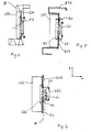
- a tail lamp arrangement is sketched, in which the contact arrangement comprises a main body GK and a cover DE, which can be braced against one another under clamping engagement of the flat cable in the x-direction.
- the main body GK is arranged on the lamp housing LG5 facing and the lid DE on the side facing away from the lamp housing of the flat cable.
- the increased installation depth in the x-direction is taken into account in the support in that an opening AU is provided in the support wall GW5 of the support QT5, through which at least the cover of the assembled contact arrangement protrudes.
- the tension between the base body GK and cover DE can at the same time serve for fastening the luminaire housing to the carrier when the lid projects beyond the edges of the recess on the side of the carrier wall facing away from the luminaire housing.
- a recess GV can be provided for the positive reception of the flat cable.
- the contact arrangement consists of a base body GK6 and a cover DE6, between which the flat cable is clamped.
- the flat cable KT has the cable cores in two adder planes E1 and E2 spaced apart in the x-direction. Cores of the wire E1 are contacted via contacts in the body GK6, cores in the wire E2 via contacts in the lid DE6. Of the contacts in the lid DE6 lead electrical connection lines VL, which may contain connectors or flexible cable sections, to the light housing LG6.
- the flat cable KT runs outside the wall recess AU on the side of the wall GW6 of the carrier QT facing away from the luminaire housing.
Landscapes
- Engineering & Computer Science (AREA)
- Mechanical Engineering (AREA)
- Arrangement Of Elements, Cooling, Sealing, Or The Like Of Lighting Devices (AREA)
- Lighting Device Outwards From Vehicle And Optical Signal (AREA)
- Container Filling Or Packaging Operations (AREA)
- Luminescent Compositions (AREA)
- Micro-Organisms Or Cultivation Processes Thereof (AREA)
- Insulated Conductors (AREA)
Applications Claiming Priority (1)
| Application Number | Priority Date | Filing Date | Title |
|---|---|---|---|
| DE102004043083A DE102004043083A1 (de) | 2004-09-07 | 2004-09-07 | Heckleuchtenanordnung |
Publications (2)
| Publication Number | Publication Date |
|---|---|
| EP1632392A1 EP1632392A1 (de) | 2006-03-08 |
| EP1632392B1 true EP1632392B1 (de) | 2007-10-17 |
Family
ID=35385706
Family Applications (1)
| Application Number | Title | Priority Date | Filing Date |
|---|---|---|---|
| EP05016920A Expired - Lifetime EP1632392B1 (de) | 2004-09-07 | 2005-08-04 | Heckleuchtenanordnung |
Country Status (4)
| Country | Link |
|---|---|
| EP (1) | EP1632392B1 (es) |
| AT (1) | ATE375892T1 (es) |
| DE (2) | DE102004043083A1 (es) |
| ES (1) | ES2296019T3 (es) |
Families Citing this family (1)
| Publication number | Priority date | Publication date | Assignee | Title |
|---|---|---|---|---|
| CN104590391B (zh) * | 2014-12-09 | 2017-06-13 | 新兴能源装备股份有限公司 | 一种车辆后防护栏挡泥装置 |
Family Cites Families (9)
| Publication number | Priority date | Publication date | Assignee | Title |
|---|---|---|---|---|
| FR1586054A (es) * | 1968-10-22 | 1970-02-06 | ||
| US5025350A (en) * | 1990-04-25 | 1991-06-18 | Federal-Mogul Corporation | Vehicle clearance lamp assembly |
| US5264997A (en) * | 1992-03-04 | 1993-11-23 | Dominion Automotive Industries Corp. | Sealed, inductively powered lamp assembly |
| DE4422393C2 (de) * | 1994-06-27 | 1997-07-03 | Reiner Hirschle | Kraftfahrzeugbeleuchtungsanordnung und Verfahren zu ihrer Anbringung |
| NL1001182C2 (nl) * | 1995-09-13 | 1997-03-20 | Felua Groep | Verlichtingsarmatuur voor een voertuig. |
| DE20109961U1 (de) * | 2001-06-15 | 2001-08-30 | Röpcke, Hans, 22765 Hamburg | Schlußleuchteneinheit für Nutzfahrzeuge |
| DE10159064B4 (de) * | 2001-12-01 | 2005-10-13 | Hella Kgaa Hueck & Co. | Fahrzeugleuchte |
| US7008088B2 (en) * | 2003-02-10 | 2006-03-07 | Richard J. Pisciotti | Lighting and safety unit for trailer hitch |
| DE202004008372U1 (de) * | 2004-05-26 | 2004-07-22 | Pozzi, Carlo Maurizio | Einrichtung zur Befestigung eines Lastenträgers am Heck eines Fahrzeugs |
-
2004
- 2004-09-07 DE DE102004043083A patent/DE102004043083A1/de not_active Withdrawn
-
2005
- 2005-08-04 AT AT05016920T patent/ATE375892T1/de active
- 2005-08-04 DE DE502005001708T patent/DE502005001708D1/de not_active Expired - Lifetime
- 2005-08-04 EP EP05016920A patent/EP1632392B1/de not_active Expired - Lifetime
- 2005-08-04 ES ES05016920T patent/ES2296019T3/es not_active Expired - Lifetime
Also Published As
| Publication number | Publication date |
|---|---|
| DE102004043083A1 (de) | 2006-03-09 |
| EP1632392A1 (de) | 2006-03-08 |
| ATE375892T1 (de) | 2007-11-15 |
| ES2296019T3 (es) | 2008-04-16 |
| DE502005001708D1 (de) | 2007-11-29 |
Similar Documents
| Publication | Publication Date | Title |
|---|---|---|
| DE4243175B4 (de) | Beleuchtungseinrichtung | |
| EP1141624A1 (de) | Lichtband-system und verfahren zum montieren eines lichtband-systems | |
| DE69005597T2 (de) | Verbesserung für Multiplex-Steuergeräte für eine Anordnung elektrischer Elemente in einem Kraftfahrzeug. | |
| DE102004062039B3 (de) | Elektrische Steckdose | |
| DE102010017346A1 (de) | Leuchte für einen Fachboden eines Möbels | |
| DE202012012607U1 (de) | Signalleuchte für Fahrzeuge | |
| DE68911170T2 (de) | Leuchtstreifen, Teile für solche Leuchtstreifen und Anzeigevorrichtung mit einem solchen Leuchtstreifen sowie Verfahren zur Herstellung von Montageblöcken sowie solchen Leuchtstreifen. | |
| DE4422393C2 (de) | Kraftfahrzeugbeleuchtungsanordnung und Verfahren zu ihrer Anbringung | |
| EP1632392B1 (de) | Heckleuchtenanordnung | |
| EP3876364B1 (de) | Schienenleuchtensystem | |
| DE4409183A1 (de) | Meßinstrumentenmodul und dessen elektrische Verbindungsvorrichtung | |
| DE102007051410A1 (de) | Trägerrohr für Deckenelemente | |
| DE69413177T2 (de) | Scheinwerfer für Kraftfahrzeuge | |
| DE102004036340A1 (de) | Heckleuchtenanordnung für Lastfahrzeuge, insbesondere Anhänger | |
| DE102006007101A1 (de) | Heckleuchtenanordnung, insbesondere für Nutzfahrzeuge | |
| EP3627045B1 (de) | Leuchtmitteleinsatzmodul | |
| DE4447719C2 (de) | Kabelführungsgehäuse | |
| DE102021212616A1 (de) | Leuchte mit Tragprofil, Stromführungsschiene und Stecker | |
| EP3234459B1 (de) | Modulare beleuchtungseinrichtung | |
| EP4042524A1 (de) | Tragschiene sowie tragschienensystem mit tragschiene | |
| EP1621409A2 (de) | Beleuchtungsanordnung eines Lastfahrzeugs, insbesondere eines Anhängers, sowie Kabelverbinder hierfür | |
| EP1690735B1 (de) | Fahrzeugleuchtenanordnung | |
| AT523010B1 (de) | Lichteinsatz, Verfahren zu dessen Herstellung und Beleuchtungssystem | |
| DE102016218677A1 (de) | Beleuchtungsvorrichtung für ein Kraftfahrzeug | |
| DE102016114232A1 (de) | Beleuchtungsvorrichtung für ein Fahrzeug |
Legal Events
| Date | Code | Title | Description |
|---|---|---|---|
| PUAI | Public reference made under article 153(3) epc to a published international application that has entered the european phase |
Free format text: ORIGINAL CODE: 0009012 |
|
| AK | Designated contracting states |
Kind code of ref document: A1 Designated state(s): AT BE BG CH CY CZ DE DK EE ES FI FR GB GR HU IE IS IT LI LT LU LV MC NL PL PT RO SE SI SK TR |
|
| AX | Request for extension of the european patent |
Extension state: AL BA HR MK YU |
|
| RAP1 | Party data changed (applicant data changed or rights of an application transferred) |
Owner name: KOMPLED GMBH & CO. KG |
|
| 17P | Request for examination filed |
Effective date: 20060908 |
|
| AKX | Designation fees paid |
Designated state(s): AT BE BG CH CY CZ DE DK EE ES FI FR GB GR HU IE IS IT LI LT LU LV MC NL PL PT RO SE SI SK TR |
|
| GRAP | Despatch of communication of intention to grant a patent |
Free format text: ORIGINAL CODE: EPIDOSNIGR1 |
|
| GRAS | Grant fee paid |
Free format text: ORIGINAL CODE: EPIDOSNIGR3 |
|
| GRAA | (expected) grant |
Free format text: ORIGINAL CODE: 0009210 |
|
| AK | Designated contracting states |
Kind code of ref document: B1 Designated state(s): AT BE BG CH CY CZ DE DK EE ES FI FR GB GR HU IE IS IT LI LT LU LV MC NL PL PT RO SE SI SK TR |
|
| REG | Reference to a national code |
Ref country code: GB Ref legal event code: FG4D Free format text: NOT ENGLISH |
|
| REG | Reference to a national code |
Ref country code: CH Ref legal event code: EP |
|
| REG | Reference to a national code |
Ref country code: IE Ref legal event code: FG4D Free format text: LANGUAGE OF EP DOCUMENT: GERMAN |
|
| REF | Corresponds to: |
Ref document number: 502005001708 Country of ref document: DE Date of ref document: 20071129 Kind code of ref document: P |
|
| NLV1 | Nl: lapsed or annulled due to failure to fulfill the requirements of art. 29p and 29m of the patents act | ||
| REG | Reference to a national code |
Ref country code: ES Ref legal event code: FG2A Ref document number: 2296019 Country of ref document: ES Kind code of ref document: T3 |
|
| ET | Fr: translation filed | ||
| PG25 | Lapsed in a contracting state [announced via postgrant information from national office to epo] |
Ref country code: NL Free format text: LAPSE BECAUSE OF FAILURE TO SUBMIT A TRANSLATION OF THE DESCRIPTION OR TO PAY THE FEE WITHIN THE PRESCRIBED TIME-LIMIT Effective date: 20071017 Ref country code: SE Free format text: LAPSE BECAUSE OF FAILURE TO SUBMIT A TRANSLATION OF THE DESCRIPTION OR TO PAY THE FEE WITHIN THE PRESCRIBED TIME-LIMIT Effective date: 20080117 |
|
| GBV | Gb: ep patent (uk) treated as always having been void in accordance with gb section 77(7)/1977 [no translation filed] | ||
| PG25 | Lapsed in a contracting state [announced via postgrant information from national office to epo] |
Ref country code: SI Free format text: LAPSE BECAUSE OF FAILURE TO SUBMIT A TRANSLATION OF THE DESCRIPTION OR TO PAY THE FEE WITHIN THE PRESCRIBED TIME-LIMIT Effective date: 20071017 Ref country code: PL Free format text: LAPSE BECAUSE OF FAILURE TO SUBMIT A TRANSLATION OF THE DESCRIPTION OR TO PAY THE FEE WITHIN THE PRESCRIBED TIME-LIMIT Effective date: 20071017 Ref country code: BG Free format text: LAPSE BECAUSE OF FAILURE TO SUBMIT A TRANSLATION OF THE DESCRIPTION OR TO PAY THE FEE WITHIN THE PRESCRIBED TIME-LIMIT Effective date: 20080117 Ref country code: IS Free format text: LAPSE BECAUSE OF FAILURE TO SUBMIT A TRANSLATION OF THE DESCRIPTION OR TO PAY THE FEE WITHIN THE PRESCRIBED TIME-LIMIT Effective date: 20080217 Ref country code: LT Free format text: LAPSE BECAUSE OF FAILURE TO SUBMIT A TRANSLATION OF THE DESCRIPTION OR TO PAY THE FEE WITHIN THE PRESCRIBED TIME-LIMIT Effective date: 20071017 Ref country code: PT Free format text: LAPSE BECAUSE OF FAILURE TO SUBMIT A TRANSLATION OF THE DESCRIPTION OR TO PAY THE FEE WITHIN THE PRESCRIBED TIME-LIMIT Effective date: 20080317 Ref country code: LV Free format text: LAPSE BECAUSE OF FAILURE TO SUBMIT A TRANSLATION OF THE DESCRIPTION OR TO PAY THE FEE WITHIN THE PRESCRIBED TIME-LIMIT Effective date: 20071017 |
|
| REG | Reference to a national code |
Ref country code: IE Ref legal event code: FD4D |
|
| PG25 | Lapsed in a contracting state [announced via postgrant information from national office to epo] |
Ref country code: DK Free format text: LAPSE BECAUSE OF FAILURE TO SUBMIT A TRANSLATION OF THE DESCRIPTION OR TO PAY THE FEE WITHIN THE PRESCRIBED TIME-LIMIT Effective date: 20071017 Ref country code: CZ Free format text: LAPSE BECAUSE OF FAILURE TO SUBMIT A TRANSLATION OF THE DESCRIPTION OR TO PAY THE FEE WITHIN THE PRESCRIBED TIME-LIMIT Effective date: 20071017 |
|
| PLBE | No opposition filed within time limit |
Free format text: ORIGINAL CODE: 0009261 |
|
| STAA | Information on the status of an ep patent application or granted ep patent |
Free format text: STATUS: NO OPPOSITION FILED WITHIN TIME LIMIT |
|
| PG25 | Lapsed in a contracting state [announced via postgrant information from national office to epo] |
Ref country code: RO Free format text: LAPSE BECAUSE OF FAILURE TO SUBMIT A TRANSLATION OF THE DESCRIPTION OR TO PAY THE FEE WITHIN THE PRESCRIBED TIME-LIMIT Effective date: 20071017 Ref country code: SK Free format text: LAPSE BECAUSE OF FAILURE TO SUBMIT A TRANSLATION OF THE DESCRIPTION OR TO PAY THE FEE WITHIN THE PRESCRIBED TIME-LIMIT Effective date: 20071017 |
|
| 26N | No opposition filed |
Effective date: 20080718 |
|
| PG25 | Lapsed in a contracting state [announced via postgrant information from national office to epo] |
Ref country code: IE Free format text: LAPSE BECAUSE OF FAILURE TO SUBMIT A TRANSLATION OF THE DESCRIPTION OR TO PAY THE FEE WITHIN THE PRESCRIBED TIME-LIMIT Effective date: 20071017 |
|
| PG25 | Lapsed in a contracting state [announced via postgrant information from national office to epo] |
Ref country code: GB Free format text: LAPSE BECAUSE OF FAILURE TO SUBMIT A TRANSLATION OF THE DESCRIPTION OR TO PAY THE FEE WITHIN THE PRESCRIBED TIME-LIMIT Effective date: 20071017 |
|
| PG25 | Lapsed in a contracting state [announced via postgrant information from national office to epo] |
Ref country code: GR Free format text: LAPSE BECAUSE OF FAILURE TO SUBMIT A TRANSLATION OF THE DESCRIPTION OR TO PAY THE FEE WITHIN THE PRESCRIBED TIME-LIMIT Effective date: 20080118 |
|
| PG25 | Lapsed in a contracting state [announced via postgrant information from national office to epo] |
Ref country code: FI Free format text: LAPSE BECAUSE OF FAILURE TO SUBMIT A TRANSLATION OF THE DESCRIPTION OR TO PAY THE FEE WITHIN THE PRESCRIBED TIME-LIMIT Effective date: 20071017 |
|
| PG25 | Lapsed in a contracting state [announced via postgrant information from national office to epo] |
Ref country code: MC Free format text: LAPSE BECAUSE OF NON-PAYMENT OF DUE FEES Effective date: 20080831 |
|
| PG25 | Lapsed in a contracting state [announced via postgrant information from national office to epo] |
Ref country code: EE Free format text: LAPSE BECAUSE OF FAILURE TO SUBMIT A TRANSLATION OF THE DESCRIPTION OR TO PAY THE FEE WITHIN THE PRESCRIBED TIME-LIMIT Effective date: 20071017 |
|
| PG25 | Lapsed in a contracting state [announced via postgrant information from national office to epo] |
Ref country code: CY Free format text: LAPSE BECAUSE OF FAILURE TO SUBMIT A TRANSLATION OF THE DESCRIPTION OR TO PAY THE FEE WITHIN THE PRESCRIBED TIME-LIMIT Effective date: 20071017 Ref country code: BE Free format text: LAPSE BECAUSE OF NON-PAYMENT OF DUE FEES Effective date: 20080831 |
|
| PGFP | Annual fee paid to national office [announced via postgrant information from national office to epo] |
Ref country code: ES Payment date: 20090821 Year of fee payment: 5 |
|
| REG | Reference to a national code |
Ref country code: CH Ref legal event code: PL |
|
| PG25 | Lapsed in a contracting state [announced via postgrant information from national office to epo] |
Ref country code: CH Free format text: LAPSE BECAUSE OF NON-PAYMENT OF DUE FEES Effective date: 20090831 Ref country code: LI Free format text: LAPSE BECAUSE OF NON-PAYMENT OF DUE FEES Effective date: 20090831 |
|
| PG25 | Lapsed in a contracting state [announced via postgrant information from national office to epo] |
Ref country code: HU Free format text: LAPSE BECAUSE OF FAILURE TO SUBMIT A TRANSLATION OF THE DESCRIPTION OR TO PAY THE FEE WITHIN THE PRESCRIBED TIME-LIMIT Effective date: 20080418 Ref country code: LU Free format text: LAPSE BECAUSE OF NON-PAYMENT OF DUE FEES Effective date: 20080804 |
|
| PG25 | Lapsed in a contracting state [announced via postgrant information from national office to epo] |
Ref country code: TR Free format text: LAPSE BECAUSE OF FAILURE TO SUBMIT A TRANSLATION OF THE DESCRIPTION OR TO PAY THE FEE WITHIN THE PRESCRIBED TIME-LIMIT Effective date: 20071017 |
|
| PGFP | Annual fee paid to national office [announced via postgrant information from national office to epo] |
Ref country code: AT Payment date: 20100820 Year of fee payment: 6 Ref country code: DE Payment date: 20100831 Year of fee payment: 6 Ref country code: FR Payment date: 20100901 Year of fee payment: 6 |
|
| PG25 | Lapsed in a contracting state [announced via postgrant information from national office to epo] |
Ref country code: IT Free format text: LAPSE BECAUSE OF NON-PAYMENT OF DUE FEES Effective date: 20080831 |
|
| REG | Reference to a national code |
Ref country code: ES Ref legal event code: FD2A Effective date: 20111019 |
|
| PG25 | Lapsed in a contracting state [announced via postgrant information from national office to epo] |
Ref country code: ES Free format text: LAPSE BECAUSE OF NON-PAYMENT OF DUE FEES Effective date: 20100805 |
|
| REG | Reference to a national code |
Ref country code: FR Ref legal event code: ST Effective date: 20120430 |
|
| REG | Reference to a national code |
Ref country code: DE Ref legal event code: R119 Ref document number: 502005001708 Country of ref document: DE Effective date: 20120301 |
|
| PG25 | Lapsed in a contracting state [announced via postgrant information from national office to epo] |
Ref country code: FR Free format text: LAPSE BECAUSE OF NON-PAYMENT OF DUE FEES Effective date: 20110831 |
|
| REG | Reference to a national code |
Ref country code: AT Ref legal event code: MM01 Ref document number: 375892 Country of ref document: AT Kind code of ref document: T Effective date: 20110804 |
|
| PG25 | Lapsed in a contracting state [announced via postgrant information from national office to epo] |
Ref country code: AT Free format text: LAPSE BECAUSE OF NON-PAYMENT OF DUE FEES Effective date: 20110804 |
|
| PG25 | Lapsed in a contracting state [announced via postgrant information from national office to epo] |
Ref country code: DE Free format text: LAPSE BECAUSE OF NON-PAYMENT OF DUE FEES Effective date: 20120301 |